EP3986616B1 - Aktenvernichter - Google Patents
Aktenvernichter Download PDFInfo
- Publication number
- EP3986616B1 EP3986616B1 EP20749864.3A EP20749864A EP3986616B1 EP 3986616 B1 EP3986616 B1 EP 3986616B1 EP 20749864 A EP20749864 A EP 20749864A EP 3986616 B1 EP3986616 B1 EP 3986616B1
- Authority
- EP
- European Patent Office
- Prior art keywords
- insertion slot
- document shredder
- draw
- shredder according
- sheet material
- Prior art date
- Legal status (The legal status is an assumption and is not a legal conclusion. Google has not performed a legal analysis and makes no representation as to the accuracy of the status listed.)
- Active
Links
Images


Classifications
-
- B—PERFORMING OPERATIONS; TRANSPORTING
- B02—CRUSHING, PULVERISING, OR DISINTEGRATING; PREPARATORY TREATMENT OF GRAIN FOR MILLING
- B02C—CRUSHING, PULVERISING, OR DISINTEGRATING IN GENERAL; MILLING GRAIN
- B02C18/00—Disintegrating by knives or other cutting or tearing members which chop material into fragments
- B02C18/06—Disintegrating by knives or other cutting or tearing members which chop material into fragments with rotating knives
- B02C18/16—Details
- B02C18/22—Feed or discharge means
- B02C18/2225—Feed means
- B02C18/2291—Feed chute arrangements
-
- B—PERFORMING OPERATIONS; TRANSPORTING
- B02—CRUSHING, PULVERISING, OR DISINTEGRATING; PREPARATORY TREATMENT OF GRAIN FOR MILLING
- B02C—CRUSHING, PULVERISING, OR DISINTEGRATING IN GENERAL; MILLING GRAIN
- B02C18/00—Disintegrating by knives or other cutting or tearing members which chop material into fragments
- B02C18/0007—Disintegrating by knives or other cutting or tearing members which chop material into fragments specially adapted for disintegrating documents
-
- B—PERFORMING OPERATIONS; TRANSPORTING
- B02—CRUSHING, PULVERISING, OR DISINTEGRATING; PREPARATORY TREATMENT OF GRAIN FOR MILLING
- B02C—CRUSHING, PULVERISING, OR DISINTEGRATING IN GENERAL; MILLING GRAIN
- B02C18/00—Disintegrating by knives or other cutting or tearing members which chop material into fragments
- B02C18/06—Disintegrating by knives or other cutting or tearing members which chop material into fragments with rotating knives
- B02C18/16—Details
- B02C18/22—Feed or discharge means
- B02C18/2225—Feed means
- B02C18/2283—Feed means using rollers
-
- B—PERFORMING OPERATIONS; TRANSPORTING
- B02—CRUSHING, PULVERISING, OR DISINTEGRATING; PREPARATORY TREATMENT OF GRAIN FOR MILLING
- B02C—CRUSHING, PULVERISING, OR DISINTEGRATING IN GENERAL; MILLING GRAIN
- B02C18/00—Disintegrating by knives or other cutting or tearing members which chop material into fragments
- B02C18/0007—Disintegrating by knives or other cutting or tearing members which chop material into fragments specially adapted for disintegrating documents
- B02C2018/003—Removing clips, pins or staples before disintegrating
Definitions
- the invention relates to a document shredder according to the preamble of claim 1.
- Document shredders of the type mentioned are known in different versions. For example, from the GB 2 504 785 A or DE 10 2017 118 889 A1 Such a document shredder is known, the housing of which has an insertion slot on its top in the ceiling wall for the manual insertion of sheet material to be shredded. Furthermore (cf. for example DE 10 2014 113 862 A1 ) Document shredder with automatic sheet material feeder according to the preamble of claim 1. These have a receiving compartment for receiving the sheet material, in the bottom of which the insertion slot is located. The sheet material picked up in the receiving compartment is gripped by feed rollers arranged on both sides of the insertion slot and pulled into the insertion slot.
- the insertion slot can be located in the center of the receiving compartment or off-center.
- the problem with both types of document shredders described is that the parts of folded sheet material arranged on both sides of the fold are pressed against one another by the feed rollers and can be easily drawn into the insertion slot, but that the parts of the sheet material arranged on both sides of the fold are in the areas next to the feed rollers stand apart from each other and this makes feeding into the insertion slot more difficult.
- This disadvantage occurs particularly with document shredders with automatic sheet material feed, as the sheet material is always folded when fed into these document shredders.
- the invention is based on the idea of making the insertion slot wider in those places where it is expected that the sheet material to be fed in has a greater thickness. This is particularly the case in the areas in which the parts of folded sheet material arranged on both sides of the fold are further apart from one another. It is possible for the insertion slot to be widened only in one of the end regions delimited by one of the slot ends. However, it is preferred that it is widened in both end areas. In particular, it is possible for the insertion slot to widen in one end region or in both end regions towards the respective slot end transversely to the longitudinal extent.
- the sheet material can be drawn in by the sheet material being gripped by the cutting tools.
- the document shredder has at least two feed rollers, which are rotatably mounted in pairs between the housing wall and the cutting mechanism and are driven in opposite directions by a motor, for drawing the sheet material into the insertion slot, with a gap extending parallel to the longitudinal extent between the feed rollers of a pair of feed rollers for pulling the sheet material through is arranged. It is possible for the document shredder to only have one pair of feed rollers.
- each pair of feed rollers having a first and a second feed roller and wherein the first feed rollers are rotatably mounted about a common first and the second feed rollers about a common second axis of rotation, the axes of rotation not being continuously physical must be trained.
- the insertion slot in the end areas towards the slot ends is transverse to the longitudinal extent widened, it is preferred that the insertion slot has a constant width in at least one central region, which is arranged between the end regions, measured perpendicular to its longitudinal extent.
- the feed rollers are then preferably arranged between a central region and one of the end regions or between two central regions.
- the insertion slot can thus be made narrow and with a constant width in the areas in which the parts of folded sheet material located on both sides of the fold are pressed together by means of the feed rollers.
- the insertion slot expediently opens into a support surface of the housing wall, on which the sheet material to be shredded can be placed, and the feed rollers extend with their lateral surfaces up to the support surface or the lateral surfaces protrude beyond the support surface.
- This measure makes it easier to grip the sheet material by means of a frictional connection between the feed rollers and the sheet material.
- the frictional connection can be increased by a pressure piece pressing towards the support surface towards the stack of sheets.
- the insertion slot it is possible for the insertion slot to widen in one or more steps in the end regions towards the slot ends. However, it is preferred that it widens continuously at least in sections and preferably has straight boundary lines. In addition, it is preferred that the end regions are identical and lie opposite each other in a mirror-symmetrical manner, while the insertion slot is also preferably mirror-symmetrical with respect to a center line running in its longitudinal extent.
- the insertion slot is delimited by guide elements on its long sides at least a little way in the direction of the cutting mechanism.
- the distance between the guide elements is reduced at least partially towards the cutting mechanism, so that parts of the sheet material that initially protrude from one another are compressed more and more in order to reduce their thickness the closer they come to the cutting mechanism.
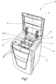
- the document shredder 10 shown in the drawing has a housing 12 which has a cover 14 articulated by means of hinges on its top. Below the lid 14 there is a receiving compartment 16 for sheet material, which is accessible when the lid is open, so that sheet material can be inserted, as in Fig. 1 shown.
- the bottom of the receiving compartment 16 is formed by a housing wall 18, the top of which serves as a support surface 20 for the sheet material.
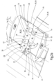
- a housing wall 18 In the housing wall 18 there is an insertion slot 22, through which sheet material resting on the support surface 20 can be drawn in and fed to a cutting unit, which is arranged in the housing 12 under the housing wall 18 and is not shown in detail, the cutting tools 24 of which are in Fig. 2b are indicated.
- the document shredder 10 also has three pairs of feed rollers 26, each of which has a first feed roller 28 and a second feed roller 30. These are each rotatably mounted about an axis of rotation arranged above the cutting unit and below the housing wall 18, the first feed rollers 28 being rotatable about a common first axis of rotation and the second feed rollers 30 being rotatable about a common second axis of rotation.
- the axes of rotation each extend parallel to a longitudinal extent of the insertion slot 22, which runs between the two slot ends 32, which form the narrow sides of the insertion slot 22.
- the lateral surfaces 36 of the feed rollers 28, 30 protrude somewhat beyond the support surface 20 so that the sheet material rests directly on them and through friction can be taken.
- a pressure piece 35 on the lid 14 that presses on the stack of sheets improves the frictional connection.
- the first feed rollers 28 rotate in opposite directions to the second feed rollers 30, and the feed rollers 28, 30 are driven by the same motor as the cutting tools 24.
- the insertion slot 22 widens transversely to the longitudinal extent in two end regions 38 towards the slot ends 32. This widening occurs continuously, as in Fig. 2a , 2 B shown.
- the insertion slot 22 is mirror-symmetrical with respect to a center plane extending perpendicular to its longitudinal extent and also mirror-symmetrical with respect to a center line running in its longitudinal extent.
- Guide elements 40 also extend somewhat from the housing wall 18 in the direction of the cutting tools 24, which delimit the insertion slot 22 on both sides in the support surface 20 starting from its longitudinal sides 42, which run parallel to the longitudinal extension.
- middle areas 44 arranged between the end areas 38, the width of the insertion slot 22 is constant, with the feed rollers 28, 30 each being arranged between one of the middle areas 44 and one of the end areas 38 or between two middle areas 44, so that the long sides 42 do not run continuously.
- the guide elements 40 extend somewhat towards one another, so that the insertion slot narrows towards the cutting elements 24.
- Fig. 3a to 3d Four different geometries of the insertion slot 22 are shown schematically. According to Fig. 3a the insertion slot 22 widens continuously in its end regions 38 towards the slot ends 32 while it according to yourself Fig. 3b in both end areas 38 widened in one step and according to Fig. 3c has approximately circular end regions 38 in plan view. Eventually it widens accordingly Fig. 3d in the direction away from the slot ends 32.
- the guide elements 40 are shown with openings in the end regions 38. But they can also be closed and have a smooth surface.
- the invention relates to a document shredder 10 with a housing 12 having an insertion slot 22 in a housing wall 18 for inserting sheet material, the insertion slot 22 having a longitudinal extension between two slot ends 32, and with a motor-driven one arranged in the housing 12 Cutting tools 24 for shredding the cutting mechanism containing sheet material.
- the insertion slot 22 is widened transversely to the longitudinal extent in at least one end region 38 delimited by one of the slot ends 32.
Landscapes
- Engineering & Computer Science (AREA)
- Food Science & Technology (AREA)
- Crushing And Pulverization Processes (AREA)
Description
- Die Erfindung betrifft einen Aktenvernichter gemäß Oberbegriff des Anspruchs 1. Aktenvernichter der eingangs genannten Art sind in unterschiedlichen Ausführungen bekannt. So ist beispielsweise aus der
GB 2 504 785 A DE 10 2017 118 889 A1 ein solcher Aktenvernichter bekannt, dessen Gehäuse an seiner Oberseite in der Deckenwand einen Einführschlitz zum manuellen Einführen von zu zerkleinerndem Blattgut aufweist. Desweiteren sind (vgl. beispielsweiseDE 10 2014 113 862 A1 ) Aktenvernichter mit automatischem Blattguteinzug gemäß Oberbegriff des Anspruchs 1 bekannt. Diese weisen ein Aufnahmefach für die Aufnahme des Blattguts auf, in dessen Boden sich der Einführschlitz befindet. Das im Aufnahmefach aufgenommene Blattgut wird durch beiderseits des Einführschlitzes angeordnete Einzugsrollen ergriffen und in den Einführschlitz gezogen. Der Einführschlitz kann in der Mitte des Aufnahmefachs angeordnet sein oder außermittig. Bei beiden beschriebenen Arten von Aktenvernichtern besteht das Problem, dass die beiderseits des Falzes angeordneten Partien von gefaltetem Blattgut zwar durch die Einzugsrollen aufeinander gedrückt werden und gut in den Einführschlitz eingezogen werden können, dass aber die beiderseits des Falzes angeordneten Partien des Blattguts in den Bereichen neben den Einzugsrollen voneinander abstehen und der Einzug in den Einführschlitz dadurch erschwert wird. Dieser Nachteil tritt besonders bei den Aktenvernichtern mit automatischem Blattguteinzug auf, da das Blattgut bei diesen Aktenvernichtern beim Einzug stets gefaltet wird. - Es ist daher Aufgabe der Erfindung, einen Aktenvernichter der eingangs genannten Art derart weiterzubilden, dass der Blattguteinzug verbessert wird.
- Diese Aufgabe wird erfindungsgemäß durch einen Aktenvernichter mit den Merkmalen des Anspruchs 1 gelöst. Vorteilhafte Weiterbildungen der Erfindung sind Gegenstand der abhängigen Ansprüche.
- Der Erfindung liegt der Gedanke zugrunde, den Einführschlitz an solchen Stellen breiter auszugestalten, an denen zu erwarten ist, dass das einzuziehende Blattgut eine größere Dicke aufweist. Dies ist insbesondere in den Bereichen der Fall, in denen die beiderseits des Falzes angeordneten Partien von gefaltetem Blattgut weiter voneinander abstehen. Dabei ist es möglich, dass der Einführschlitz nur in einem der durch eines der Schlitzenden begrenzten Endbereiche verbreitert ist. Es wird jedoch bevorzugt, dass er in beiden Endbereichen verbreitert ist. Insbesondere ist es möglich, dass sich der Einführschlitz in einem Endbereich oder in beiden Endbereichen zum jeweiligen Schlitzende hin quer zur Längserstreckung verbreitert.
- Der Blattguteinzug kann dadurch erfolgen, dass das Blattgut von den Schneidwerkzeugen ergriffen wird. Es wird jedoch bevorzugt, dass der Aktenvernichter mindestens zwei paarweise zwischen der Gehäusewand und dem Schneidwerk drehbar gelagerte, motorisch gegenläufig angetriebene Einzugsrollen zum Einziehen des Blattguts in den Einführschlitz aufweist, wobei zwischen den Einzugsrollen eines Einzugsrollenpaars ein sich parallel zur Längserstreckung erstreckender Spalt zum Durchziehen des Blattguts angeordnet ist. Dabei ist es möglich, dass der Aktenvernichter nur ein Einzugsrollenpaar aufweist. Es wird jedoch bevorzugt, dass er mindestens zwei Einzugsrollenpaare aufweist, wobei jedes Einzugsrollenpaar eine erste und eine zweite Einzugsrolle aufweist und wobei die ersten Einzugsrollen um eine gemeinsame erste und die zweiten Einzugsrollen um eine gemeinsame zweite Drehachse drehbar gelagert sind, wobei die Drehachsen nicht durchgehend körperlich ausgebildet sein müssen. Während sich der Einführschlitz in den Endbereichen zu den Schlitzenden hin quer zur Längserstreckung verbreitert, wird bevorzugt, dass der Einführschlitz in mindestens einem Mittelbereich, der zwischen den Endbereichen angeordnet ist, senkrecht zu seiner Längserstreckung gemessen eine konstante Breite aufweist. Die Einzugsrollen sind dann vorzugsweise zwischen einem Mittelbereich und einem der Endbereiche oder zwischen zwei Mittelbereichen angeordnet. Der Einführschlitz kann somit in den Bereichen schmal und mit konstanter Breite gestaltet werden, in denen ein Aneinanderpressen der beiderseits des Falzes gelegenen Partien von gefaltetem Blattgut mittels der Einzugsrollen gewährleistet ist.
- Zweckmäßig mündet der Einführschlitz in eine Auflagefläche der Gehäusewand, auf der das zu zerkleinernde Blattgut aufgelegt werden kann, und die Einzugsrollen erstrecken sich mit ihren Mantelflächen bis zur Auflagefläche oder die Mantelflächen stehen über die Auflagefläche vor. Diese Maßnahme erleichtert ein Greifen des Blattguts mittels Reibschluss zwischen den Einzugsrollen und dem Blattgut. Der Reibschluss kann verstärkt werden, indem ein Druckstück in Richtung auf die Auflagefläche zu auf den Blattgutstapel drückt.
- Es ist möglich, dass sich der Einführschlitz in den Endbereichen zu den Schlitzenden hin in einem oder mehreren Schritten verbreitert. Es wird jedoch bevorzugt, dass er sich zumindest abschnittsweise kontinuierlich verbreitert und dabei vorzugsweise gerade Begrenzungslinien aufweist. Zudem wird bevorzugt, dass die Endbereiche identisch ausgebildet sind und sich spiegelsymmetrisch gegenüberliegen, während der Einführschlitz zudem vorzugsweise bezüglich einer in seiner Längserstreckung verlaufenden Mittellinie spiegelsymmetrisch ist.
- Eine weitere Verbesserung des Blattguteinzugs ergibt sich, wenn gemäß einer vorteilhaften Weiterbildung der Erfindung der Einführschlitz an seinen Längsseiten zumindest ein Stück weit in Richtung zum Schneidwerk hin von Leitelementen begrenzt wird. Vorteilhaft verringert sich der Abstand der Leitelemente zumindest teilweise zum Schneidwerk hin, so dass zunächst voneinander abstehende Partien des Blattguts mehr und mehr zusammengedrückt werden, um ihre Dicke zu verringern, je näher sie dem Schneidwerk kommen.
- Im Folgenden wird die Erfindung anhand eines in der Zeichnung schematisch dargestellten Ausführungsbeispiels näher erläutert. Es zeigen
-
Fig. 1 einen Aktenvernichter in perspektivischer Ansicht; -
Fig. 2a ,2b Detaildarstellungen des Aktenvernichters gemäßFig. 1 und -
Fig. 3a bis 3d schematische Darstellungen alternativer Geometrien des Einzugsschlitzes in Draufsicht. - Der in der Zeichnung dargestellte Aktenvernichter 10 weist ein Gehäuse 12 auf, das an seiner Oberseite einen mittels Scharnieren angelenkten Deckel 14 aufweist. Unterhalb des Deckels 14 befindet sich ein Aufnahmefach 16 für Blattgut, das bei geöffnetem Deckel zugänglich ist, so dass Blattgut eingelegt werden kann, wie in
Fig. 1 dargestellt. Den Boden des Aufnahmefachs 16 bildet eine Gehäusewand 18, deren Oberseite als Auflagefläche 20 für das Blattgut dient. In der Gehäusewand 18 befindet sich ein Einführschlitz 22, durch den auf der Auflagefläche 20 aufliegendes Blattgut eingezogen und einem im Gehäuse 12 unter der Gehäusewand 18 angeordneten, nicht im Detail dargestellten Schneidwerk zugeführt werden kann, dessen Schneidwerkzeuge 24 inFig. 2b angedeutet sind. Der Aktenvernichter 10 weist zudem drei Einzugsrollenpaare 26 auf, die jeweils eine erste Einzugsrolle 28 und eine zweite Einzugsrolle 30 aufweisen. Diese sind jeweils drehbar um eine oberhalb des Schneidwerks und unterhalb der Gehäusewand 18 angeordneten Drehachse gelagert, wobei die ersten Einzugsrollen 28 um eine gemeinsame erste Drehachse und die zweiten Einzugsrollen 30 um eine gemeinsame zweite Drehachse drehbar sind. Die Drehachsen erstrecken sich jeweils parallel zu einer Längserstreckung des Einführschlitzes 22, die zwischen den beiden Schlitzenden 32 verläuft, welche die Schmalseiten des Einführschlitzes 22 bilden. Zwischen der ersten Einzugsrolle 28 und der zweiten Einzugsrolle 30 jedes der Einzugsrollenpaare 26 befindet sich ein Spalt 34, durch den das Blattgut durchgezogen und den Schneidwerkzeugen 24 zugeführt wird. Die Mantelflächen 36 der Einzugsrollen 28, 30 stehen ein Stück weit über die Auflagefläche 20 vor, so dass das Blattgut direkt auf ihnen aufliegt und durch Reibschluss ergriffen werden kann. Ein auf den Blattgutstapel drückendes Druckstück 35 am Deckel 14 verbessert den Reibschluss. Die ersten Einzugsrollen 28 rotieren gegenläufig zu den zweiten Einzugsrollen 30, und die Einzugsrollen 28, 30 werden mittels desselben Motors angetrieben wie die Schneidwerkzeuge 24. - Beim Einzug des Blattguts mittels der Einzugsrollen 28, 30 wird jeweils das unterste Blatt von den Einzugsrollen 28, 30 ergriffen, ungefähr in seiner Mitte gefaltet und mit dem Falz voran in den Einführschlitz 22 eingezogen. Die beiden Partien eines Blatts, die am Falz aneinander angrenzen, werden im Bereich der Spalte 34 durch die Einzugsrollen 28, 30 eng aneinander gedrückt, während sie im Bereich der Schlitzenden 32 weiter voneinander abstehen. Um auch dort ein Einführen in den Einführschlitz 22 zu erleichtern, ist erfindungsgemäß vorgesehen, dass sich der Einführschlitz 22 in zwei Endbereichen 38 zu den Schlitzenden 32 hin quer zur Längserstreckung verbreitert. Diese Verbreiterung erfolgt kontinuierlich, wie in
Fig. 2a ,2b dargestellt. Dabei ist der Einführschlitz 22 spiegelsymmetrisch im Hinblick auf eine sich senkrecht zu seiner Längserstreckung erstreckende Mittelebene und zudem spiegelsymmetrisch bezüglich einer in seiner Längserstreckung verlaufenden Mittellinie. Von der Gehäusewand 18 erstrecken sich zudem Leitelemente 40 ein Stück weit in Richtung der Schneidwerkzeuge 24, die den Einführschlitz 22 ausgehend von seinen parallel zur Längserstreckung verlaufenden Längsseiten 42 in der Auflagefläche 20 beidseitig begrenzen. In zwischen den Endbereichen 38 angeordneten Mittelbereichen 44 ist die Breite des Einführschlitzes 22 konstant, wobei die Einzugsrollen 28, 30 jeweils zwischen einem der Mittelbereiche 44 und einem der Endbereiche 38 oder zwischen zwei Mittelbereichen 44 angeordnet sind, so dass die Längsseiten 42 nicht durchgehend verlaufen. In Richtung zu den Schneidwerkzeugen 24 verlaufen die Leitelemente 40 ein Stück weit aufeinander zu, so dass sich der Einführschlitz zu den Schneidelementen 24 hin verengt. - In
Fig. 3a bis 3d sind vier unterschiedliche Geometrien des Einführschlitzes 22 schematisch dargestellt. GemäßFig. 3a verbreitert sich der Einführschlitz 22 in seinen Endbereichen 38 kontinuierlich zu den Schlitzenden 32 hin, während er sich gemäßFig. 3b in beiden Endbereichen 38 in einer Stufe verbreitert und gemäßFig. 3c in Draufsicht ungefähr kreisförmige Endbereiche 38 aufweist. Schließlich verbreitert er sich gemäßFig. 3d in Richtung von den Schlitzenden 32 weg. - In der Zeichnung werden die Leitelemente 40 mit Öffnungen in den Endbereichen 38 dargestellt. Sie können aber auch geschlossen sein und eine glatte Oberfläche aufweisen.
- Zusammenfassend ist folgendes festzuhalten: Die Erfindung betrifft einen Aktenvernichter 10 mit einem in einer Gehäusewand 18 einen Einführschlitz 22 zum Einführen von Blattgut aufweisenden Gehäuse 12, wobei der Einführschlitz 22 eine Längserstreckung zwischen zwei Schlitzenden 32 aufweist, und mit einem im Gehäuse 12 angeordneten, motorisch angetriebene Schneidwerkzeuge 24 zum Zerkleinern des Blattguts aufweisenden Schneidwerk. Erfindungsgemäß ist vorgesehen, dass sich der Einführschlitz 22 in mindestens einem durch eines der Schlitzenden 32 begrenzten Endbereiche 38 quer zur Längserstreckung verbreitert ist.
Claims (13)
- Aktenvernichter mit einem in einer Gehäusewand (18) einen Einführschlitz (22) zum Einführen von Blattgut aufweisenden Gehäuse (12), wobei der Einführschlitz (22) eine Längserstreckung zwischen zwei Schlitzenden (32) aufweist, und mit einem im Gehäuse (12) angeordneten, motorisch angetriebene Schneidwerkzeuge (24) zum Zerkleinern des Blattguts aufweisenden Schneidwerk, dadurch gekennzeichnet, dass der Einführschlitz (22) in mindestens einem durch eines der Schlitzenden (32) begrenzten Endbereich (38) quer zur Längserstreckung verbreitert ist.
- Aktenvernichter nach Anspruch 1, dadurch gekennzeichnet, dass der Einführschlitz (22) in beiden Endbereichen (38) quer zur Längserstreckung verbreitert ist.
- Aktenvernichter nach Anspruch 1 oder 2, dadurch gekennzeichnet, dass sich der Einführschlitz (22) in mindestens einem der Endbereiche (38) zum jeweiligen Schlitzende (32) hin quer zur Längserstreckung verbreitert.
- Aktenvernichter nach einem der vorangehenden Ansprüche, gekennzeichnet durch mindestens zwei paarweise zwischen der Gehäusewand (18) und dem Schneidwerk drehbar gelagerte, motorisch gegenläufig angetriebene Einzugsrollen (28, 30) zum Einziehen des Blattguts in den Einführschlitz (22), wobei zwischen den Einzugsrollen (28, 30) eines Einzugsrollenpaars (26) ein sich parallel zur Längserstreckung erstreckender Spalt (34) zum Durchziehen des Blattguts angeordnet ist.
- Aktenvernichter nach Anspruch 4, gekennzeichnet durch mindestens zwei Einzugsrollenpaare (26), wobei jedes Einzugsrollenpaar (26) eine erste (28) und eine zweite Einzugsrolle (30) aufweist und wobei die ersten Einzugsrollen (28) um eine gemeinsame erste und die zweiten Einzugsrollen (30) um eine gemeinsame zweite Drehachse drehbar gelagert sind.
- Aktenvernichter nach einem der vorangehenden Ansprüche, dadurch gekennzeichnet, dass der Einführschlitz (22) in mindestens einem Mittelbereich (44) zwischen den Endbereichen (38) senkrecht zur Längserstreckung gemessen eine konstante Breite aufweist.
- Aktenvernichter nach Anspruch 4 oder 5 und nach Anspruch 6, dadurch gekennzeichnet, dass alle Einzugsrollen (28, 30) zwischen einem Mittelbereich (44) und einem der Endbereiche (38) oder zwischen zwei Mittelbereichen (44) angeordnet sind.
- Aktenvernichter nach einem der Ansprüche 4 bis 7, dadurch gekennzeichnet, dass der Einführschlitz (22) in eine Auflagefläche (20) der Gehäusewand (18) zur Auflage von Blattgut mündet, und dass sich die Einzugsrollen (28, 30) mit ihren Mantelflächen (36) bis zur Auflagefläche (20) erstrecken oder dass die Mantelflächen (36) über die Auflagefläche (20) vorstehen.
- Aktenvernichter nach einem der vorangehenden Ansprüche, dadurch gekennzeichnet, dass sich der Einführschlitz (22) in den Endbereichen (38) zu den Schlitzenden (32) hin zumindest abschnittsweise kontinuierlich verbreitert.
- Aktenvernichter nach einem der vorangehenden Ansprüche, dadurch gekennzeichnet, dass die Endbereiche (38) identisch ausgebildet sind und sich spiegelsymmetrisch gegenüber liegen.
- Aktenvernichter nach einem der vorangehenden Ansprüche, dadurch gekennzeichnet, dass der Einführschlitz (22) bezüglich einer in seiner Längserstreckung verlaufenden Mittellinie spiegelsymmetrisch ist.
- Aktenvernichter nach einem der vorangehenden Ansprüche, dadurch gekennzeichnet, dass der Einführschlitz (22) an seinen Längsseiten zumindest ein Stück weit in Richtung zum Schneidwerk hin von Leitelementen (40) begrenzt wird.
- Aktenvernichter nach Anspruch 12, dadurch gekennzeichnet, dass sich der Abstand der Leitelemente (40) zumindest teilweise zum Schneidwerk hin verringert.
Applications Claiming Priority (2)
| Application Number | Priority Date | Filing Date | Title |
|---|---|---|---|
| DE102019126015.9A DE102019126015A1 (de) | 2019-09-26 | 2019-09-26 | Aktenvernichter |
| PCT/EP2020/071432 WO2021058180A1 (de) | 2019-09-26 | 2020-07-29 | Aktenvernichter |
Publications (2)
| Publication Number | Publication Date |
|---|---|
| EP3986616A1 EP3986616A1 (de) | 2022-04-27 |
| EP3986616B1 true EP3986616B1 (de) | 2023-09-20 |
Family
ID=71894817
Family Applications (1)
| Application Number | Title | Priority Date | Filing Date |
|---|---|---|---|
| EP20749864.3A Active EP3986616B1 (de) | 2019-09-26 | 2020-07-29 | Aktenvernichter |
Country Status (5)
| Country | Link |
|---|---|
| US (1) | US11517912B2 (de) |
| EP (1) | EP3986616B1 (de) |
| DE (1) | DE102019126015A1 (de) |
| ES (1) | ES2964910T3 (de) |
| WO (1) | WO2021058180A1 (de) |
Family Cites Families (16)
| Publication number | Priority date | Publication date | Assignee | Title |
|---|---|---|---|---|
| US5295633A (en) * | 1992-01-13 | 1994-03-22 | Fellowes Manufacturing Company | Document shredding machine with stripper and cutting mechanism therefore |
| JPH0975762A (ja) * | 1995-09-14 | 1997-03-25 | Matsushita Electric Ind Co Ltd | シュレッダ |
| US7658342B2 (en) * | 2004-06-14 | 2010-02-09 | Michilin Prosperity Co., Ltd. | Auto-feed buit-in a paper shredder |
| US20070012808A1 (en) * | 2005-07-18 | 2007-01-18 | Cheng-Chung Kao | Shredder safety device having emergency stop |
| CN201002039Y (zh) * | 2007-01-11 | 2008-01-09 | 世庆实业股份有限公司 | 碎纸机的活动式入纸口盖板 |
| GB2445543B (en) * | 2007-01-15 | 2011-08-24 | Acco Uk Ltd | A shredder arrangement |
| GB2451513B (en) * | 2007-08-02 | 2012-04-18 | Acco Uk Ltd | A shredding machine |
| US7819351B2 (en) * | 2007-09-26 | 2010-10-26 | Aron Abramson | Shredder head adapted to shred data bearing documents and bottles |
| US8196851B2 (en) * | 2010-04-16 | 2012-06-12 | Acco Uk Limited | Paper shredder with feeder |
| CN202427513U (zh) * | 2011-12-21 | 2012-09-12 | 东莞福泰电子有限公司 | 一种自动进纸碎纸机 |
| CN103567030A (zh) * | 2012-08-07 | 2014-02-12 | 致伸科技股份有限公司 | 具有容许厚度警示功能的碎纸装置 |
| US9776191B2 (en) | 2013-09-25 | 2017-10-03 | Hermann Schwelling | Method and device for shredding sheet-shaped material |
| US11027318B2 (en) * | 2017-02-15 | 2021-06-08 | Herman Chang | Autofeeder roller cleaning |
| DE102017118889B4 (de) | 2017-08-18 | 2021-09-09 | Leitz Acco Brands Gmbh & Co Kg | Aktenvernichter |
| US20200290056A1 (en) * | 2019-03-15 | 2020-09-17 | Michilin Prosperity Co., Ltd. | Energy-saving auto feed shredder |
| US20220193689A1 (en) * | 2020-12-22 | 2022-06-23 | Herman Chang | Auto-feed Paper Shredder with Dual Bottom Inputs |
-
2019
- 2019-09-26 DE DE102019126015.9A patent/DE102019126015A1/de active Pending
-
2020
- 2020-07-29 ES ES20749864T patent/ES2964910T3/es active Active
- 2020-07-29 EP EP20749864.3A patent/EP3986616B1/de active Active
- 2020-07-29 WO PCT/EP2020/071432 patent/WO2021058180A1/de not_active Ceased
- 2020-07-29 US US17/636,239 patent/US11517912B2/en active Active
Also Published As
| Publication number | Publication date |
|---|---|
| EP3986616A1 (de) | 2022-04-27 |
| US11517912B2 (en) | 2022-12-06 |
| ES2964910T3 (es) | 2024-04-10 |
| US20220266256A1 (en) | 2022-08-25 |
| WO2021058180A1 (de) | 2021-04-01 |
| DE102019126015A1 (de) | 2021-04-01 |
Similar Documents
| Publication | Publication Date | Title |
|---|---|---|
| DE3873469T2 (de) | Verfahren zum falten des papiermaterials, zum beispiel dokumente verschiedener qualitaet und laenge, die zusammen oder nach einander transportiert werden. | |
| DE2951199C2 (de) | Papierzufuhr-Kassette zur wahlweisen Aufnahme von Papierstapeln unterschiedlicher Breite | |
| DE69709686T2 (de) | Trommel für die herstellung absorbierender artikel | |
| DE3301889C2 (de) | Vorrichtung zur Abgabe von bahnförmigem Material | |
| DE4314653C2 (de) | Mehrzweckkalander | |
| DE102013107598B3 (de) | Rillvorrichtung mit drehbarer Transporteinrichtung | |
| AT519008A4 (de) | Vorrichtung zum Schnitt von Teilbändern mit vorgebbarer Breite | |
| DE3209409C2 (de) | ||
| DE3500632C2 (de) | Vorrichtung zum Durchschneiden eines oder mehrerer ganz oder teilweise übereinanderliegender Bogen | |
| EP3587283B1 (de) | Verpackungsmaschine zum verpacken mit dehnfolie und optimiertes verpackungsverfahren | |
| DE102007024543B3 (de) | Vorrichtung zur Vereinzelung von als Bandware vorliegenden Werkstücken, insbesondere Kontaktelementen | |
| DE1536849B1 (de) | Vorrichtung und Verfahren zur Herstellung von gefalteten Filtereinsaetzen aus einem Filtermaterialband | |
| DE1536485B1 (de) | Vorrichtung zum Einbinden von Buchbloecken | |
| DE69103782T2 (de) | Biegeeinheit einer Blechbiegemaschine. | |
| WO2021058180A1 (de) | Aktenvernichter | |
| DE112007001295B4 (de) | Verfahren und Vorrichtung zum Biegen eines Klingenmaterials | |
| EP4102976B1 (de) | Vorrichtung und verfahren zum formen eines strangförmigen lebensmittels | |
| DE2727060C3 (de) | Vorrichtung für die Herstellung eines Verbundprofils für Fensterrahmen o.dgl | |
| EP1803674B1 (de) | Falzvorrichtung mit feststehendem Falzschwert | |
| EP1281457B1 (de) | Vorrichtung zum Biegen von Hohlprofilstäben | |
| DE1004368B (de) | Kontinuierlich arbeitende Bandpresse, insbesondere zur Spanplattenherstellung | |
| DE102015206855B4 (de) | Vorrichtung und Verfahren zur spanlosen Bearbeitung einer geraden Kante an einer Platte | |
| DE602004008143T2 (de) | Kaschiermaschine | |
| EP3235639B1 (de) | Laminiergerät | |
| EP1862235B1 (de) | Dornschaft-Wechselbiege-Werkzeug |
Legal Events
| Date | Code | Title | Description |
|---|---|---|---|
| STAA | Information on the status of an ep patent application or granted ep patent |
Free format text: STATUS: UNKNOWN |
|
| STAA | Information on the status of an ep patent application or granted ep patent |
Free format text: STATUS: THE INTERNATIONAL PUBLICATION HAS BEEN MADE |
|
| PUAI | Public reference made under article 153(3) epc to a published international application that has entered the european phase |
Free format text: ORIGINAL CODE: 0009012 |
|
| STAA | Information on the status of an ep patent application or granted ep patent |
Free format text: STATUS: REQUEST FOR EXAMINATION WAS MADE |
|
| 17P | Request for examination filed |
Effective date: 20220118 |
|
| AK | Designated contracting states |
Kind code of ref document: A1 Designated state(s): AL AT BE BG CH CY CZ DE DK EE ES FI FR GB GR HR HU IE IS IT LI LT LU LV MC MK MT NL NO PL PT RO RS SE SI SK SM TR |
|
| DAV | Request for validation of the european patent (deleted) | ||
| DAX | Request for extension of the european patent (deleted) | ||
| GRAP | Despatch of communication of intention to grant a patent |
Free format text: ORIGINAL CODE: EPIDOSNIGR1 |
|
| STAA | Information on the status of an ep patent application or granted ep patent |
Free format text: STATUS: GRANT OF PATENT IS INTENDED |
|
| INTG | Intention to grant announced |
Effective date: 20230113 |
|
| GRAS | Grant fee paid |
Free format text: ORIGINAL CODE: EPIDOSNIGR3 |
|
| GRAJ | Information related to disapproval of communication of intention to grant by the applicant or resumption of examination proceedings by the epo deleted |
Free format text: ORIGINAL CODE: EPIDOSDIGR1 |
|
| GRAL | Information related to payment of fee for publishing/printing deleted |
Free format text: ORIGINAL CODE: EPIDOSDIGR3 |
|
| STAA | Information on the status of an ep patent application or granted ep patent |
Free format text: STATUS: REQUEST FOR EXAMINATION WAS MADE |
|
| INTC | Intention to grant announced (deleted) | ||
| GRAP | Despatch of communication of intention to grant a patent |
Free format text: ORIGINAL CODE: EPIDOSNIGR1 |
|
| STAA | Information on the status of an ep patent application or granted ep patent |
Free format text: STATUS: GRANT OF PATENT IS INTENDED |
|
| GRAA | (expected) grant |
Free format text: ORIGINAL CODE: 0009210 |
|
| STAA | Information on the status of an ep patent application or granted ep patent |
Free format text: STATUS: THE PATENT HAS BEEN GRANTED |
|
| INTG | Intention to grant announced |
Effective date: 20230803 |
|
| AK | Designated contracting states |
Kind code of ref document: B1 Designated state(s): AL AT BE BG CH CY CZ DE DK EE ES FI FR GB GR HR HU IE IS IT LI LT LU LV MC MK MT NL NO PL PT RO RS SE SI SK SM TR |
|
| REG | Reference to a national code |
Ref country code: GB Ref legal event code: FG4D Free format text: NOT ENGLISH |
|
| REG | Reference to a national code |
Ref country code: CH Ref legal event code: EP |
|
| REG | Reference to a national code |
Ref country code: DE Ref legal event code: R096 Ref document number: 502020005328 Country of ref document: DE |
|
| REG | Reference to a national code |
Ref country code: IE Ref legal event code: FG4D Free format text: LANGUAGE OF EP DOCUMENT: GERMAN |
|
| P01 | Opt-out of the competence of the unified patent court (upc) registered |
Effective date: 20231016 |
|
| REG | Reference to a national code |
Ref country code: LT Ref legal event code: MG9D |
|
| PG25 | Lapsed in a contracting state [announced via postgrant information from national office to epo] |
Ref country code: GR Free format text: LAPSE BECAUSE OF FAILURE TO SUBMIT A TRANSLATION OF THE DESCRIPTION OR TO PAY THE FEE WITHIN THE PRESCRIBED TIME-LIMIT Effective date: 20231221 |
|
| REG | Reference to a national code |
Ref country code: NL Ref legal event code: MP Effective date: 20230920 |
|
| PG25 | Lapsed in a contracting state [announced via postgrant information from national office to epo] |
Ref country code: SE Free format text: LAPSE BECAUSE OF FAILURE TO SUBMIT A TRANSLATION OF THE DESCRIPTION OR TO PAY THE FEE WITHIN THE PRESCRIBED TIME-LIMIT Effective date: 20230920 Ref country code: RS Free format text: LAPSE BECAUSE OF FAILURE TO SUBMIT A TRANSLATION OF THE DESCRIPTION OR TO PAY THE FEE WITHIN THE PRESCRIBED TIME-LIMIT Effective date: 20230920 Ref country code: NO Free format text: LAPSE BECAUSE OF FAILURE TO SUBMIT A TRANSLATION OF THE DESCRIPTION OR TO PAY THE FEE WITHIN THE PRESCRIBED TIME-LIMIT Effective date: 20231220 Ref country code: LV Free format text: LAPSE BECAUSE OF FAILURE TO SUBMIT A TRANSLATION OF THE DESCRIPTION OR TO PAY THE FEE WITHIN THE PRESCRIBED TIME-LIMIT Effective date: 20230920 Ref country code: LT Free format text: LAPSE BECAUSE OF FAILURE TO SUBMIT A TRANSLATION OF THE DESCRIPTION OR TO PAY THE FEE WITHIN THE PRESCRIBED TIME-LIMIT Effective date: 20230920 Ref country code: HR Free format text: LAPSE BECAUSE OF FAILURE TO SUBMIT A TRANSLATION OF THE DESCRIPTION OR TO PAY THE FEE WITHIN THE PRESCRIBED TIME-LIMIT Effective date: 20230920 Ref country code: GR Free format text: LAPSE BECAUSE OF FAILURE TO SUBMIT A TRANSLATION OF THE DESCRIPTION OR TO PAY THE FEE WITHIN THE PRESCRIBED TIME-LIMIT Effective date: 20231221 Ref country code: FI Free format text: LAPSE BECAUSE OF FAILURE TO SUBMIT A TRANSLATION OF THE DESCRIPTION OR TO PAY THE FEE WITHIN THE PRESCRIBED TIME-LIMIT Effective date: 20230920 |
|
| PG25 | Lapsed in a contracting state [announced via postgrant information from national office to epo] |
Ref country code: NL Free format text: LAPSE BECAUSE OF FAILURE TO SUBMIT A TRANSLATION OF THE DESCRIPTION OR TO PAY THE FEE WITHIN THE PRESCRIBED TIME-LIMIT Effective date: 20230920 |
|
| PG25 | Lapsed in a contracting state [announced via postgrant information from national office to epo] |
Ref country code: IS Free format text: LAPSE BECAUSE OF FAILURE TO SUBMIT A TRANSLATION OF THE DESCRIPTION OR TO PAY THE FEE WITHIN THE PRESCRIBED TIME-LIMIT Effective date: 20240120 |
|
| REG | Reference to a national code |
Ref country code: ES Ref legal event code: FG2A Ref document number: 2964910 Country of ref document: ES Kind code of ref document: T3 Effective date: 20240410 |
|
| PG25 | Lapsed in a contracting state [announced via postgrant information from national office to epo] |
Ref country code: SM Free format text: LAPSE BECAUSE OF FAILURE TO SUBMIT A TRANSLATION OF THE DESCRIPTION OR TO PAY THE FEE WITHIN THE PRESCRIBED TIME-LIMIT Effective date: 20230920 Ref country code: RO Free format text: LAPSE BECAUSE OF FAILURE TO SUBMIT A TRANSLATION OF THE DESCRIPTION OR TO PAY THE FEE WITHIN THE PRESCRIBED TIME-LIMIT Effective date: 20230920 Ref country code: IS Free format text: LAPSE BECAUSE OF FAILURE TO SUBMIT A TRANSLATION OF THE DESCRIPTION OR TO PAY THE FEE WITHIN THE PRESCRIBED TIME-LIMIT Effective date: 20240120 Ref country code: EE Free format text: LAPSE BECAUSE OF FAILURE TO SUBMIT A TRANSLATION OF THE DESCRIPTION OR TO PAY THE FEE WITHIN THE PRESCRIBED TIME-LIMIT Effective date: 20230920 Ref country code: CZ Free format text: LAPSE BECAUSE OF FAILURE TO SUBMIT A TRANSLATION OF THE DESCRIPTION OR TO PAY THE FEE WITHIN THE PRESCRIBED TIME-LIMIT Effective date: 20230920 Ref country code: PT Free format text: LAPSE BECAUSE OF FAILURE TO SUBMIT A TRANSLATION OF THE DESCRIPTION OR TO PAY THE FEE WITHIN THE PRESCRIBED TIME-LIMIT Effective date: 20240122 Ref country code: SK Free format text: LAPSE BECAUSE OF FAILURE TO SUBMIT A TRANSLATION OF THE DESCRIPTION OR TO PAY THE FEE WITHIN THE PRESCRIBED TIME-LIMIT Effective date: 20230920 |
|
| PG25 | Lapsed in a contracting state [announced via postgrant information from national office to epo] |
Ref country code: PL Free format text: LAPSE BECAUSE OF FAILURE TO SUBMIT A TRANSLATION OF THE DESCRIPTION OR TO PAY THE FEE WITHIN THE PRESCRIBED TIME-LIMIT Effective date: 20230920 |
|
| REG | Reference to a national code |
Ref country code: DE Ref legal event code: R097 Ref document number: 502020005328 Country of ref document: DE |
|
| PG25 | Lapsed in a contracting state [announced via postgrant information from national office to epo] |
Ref country code: DK Free format text: LAPSE BECAUSE OF FAILURE TO SUBMIT A TRANSLATION OF THE DESCRIPTION OR TO PAY THE FEE WITHIN THE PRESCRIBED TIME-LIMIT Effective date: 20230920 |
|
| PLBE | No opposition filed within time limit |
Free format text: ORIGINAL CODE: 0009261 |
|
| STAA | Information on the status of an ep patent application or granted ep patent |
Free format text: STATUS: NO OPPOSITION FILED WITHIN TIME LIMIT |
|
| PG25 | Lapsed in a contracting state [announced via postgrant information from national office to epo] |
Ref country code: DK Free format text: LAPSE BECAUSE OF FAILURE TO SUBMIT A TRANSLATION OF THE DESCRIPTION OR TO PAY THE FEE WITHIN THE PRESCRIBED TIME-LIMIT Effective date: 20230920 |
|
| 26N | No opposition filed |
Effective date: 20240621 |
|
| PG25 | Lapsed in a contracting state [announced via postgrant information from national office to epo] |
Ref country code: SI Free format text: LAPSE BECAUSE OF FAILURE TO SUBMIT A TRANSLATION OF THE DESCRIPTION OR TO PAY THE FEE WITHIN THE PRESCRIBED TIME-LIMIT Effective date: 20230920 |
|
| PG25 | Lapsed in a contracting state [announced via postgrant information from national office to epo] |
Ref country code: SI Free format text: LAPSE BECAUSE OF FAILURE TO SUBMIT A TRANSLATION OF THE DESCRIPTION OR TO PAY THE FEE WITHIN THE PRESCRIBED TIME-LIMIT Effective date: 20230920 |
|
| PG25 | Lapsed in a contracting state [announced via postgrant information from national office to epo] |
Ref country code: BG Free format text: LAPSE BECAUSE OF FAILURE TO SUBMIT A TRANSLATION OF THE DESCRIPTION OR TO PAY THE FEE WITHIN THE PRESCRIBED TIME-LIMIT Effective date: 20230920 |
|
| PG25 | Lapsed in a contracting state [announced via postgrant information from national office to epo] |
Ref country code: BG Free format text: LAPSE BECAUSE OF FAILURE TO SUBMIT A TRANSLATION OF THE DESCRIPTION OR TO PAY THE FEE WITHIN THE PRESCRIBED TIME-LIMIT Effective date: 20230920 |
|
| PG25 | Lapsed in a contracting state [announced via postgrant information from national office to epo] |
Ref country code: MC Free format text: LAPSE BECAUSE OF FAILURE TO SUBMIT A TRANSLATION OF THE DESCRIPTION OR TO PAY THE FEE WITHIN THE PRESCRIBED TIME-LIMIT Effective date: 20230920 |
|
| REG | Reference to a national code |
Ref country code: CH Ref legal event code: PL |
|
| PG25 | Lapsed in a contracting state [announced via postgrant information from national office to epo] |
Ref country code: LU Free format text: LAPSE BECAUSE OF NON-PAYMENT OF DUE FEES Effective date: 20240729 |
|
| PG25 | Lapsed in a contracting state [announced via postgrant information from national office to epo] |
Ref country code: LU Free format text: LAPSE BECAUSE OF NON-PAYMENT OF DUE FEES Effective date: 20240729 |
|
| PG25 | Lapsed in a contracting state [announced via postgrant information from national office to epo] |
Ref country code: BE Free format text: LAPSE BECAUSE OF NON-PAYMENT OF DUE FEES Effective date: 20240731 Ref country code: CH Free format text: LAPSE BECAUSE OF NON-PAYMENT OF DUE FEES Effective date: 20240731 |
|
| REG | Reference to a national code |
Ref country code: BE Ref legal event code: MM Effective date: 20240731 |
|
| PG25 | Lapsed in a contracting state [announced via postgrant information from national office to epo] |
Ref country code: IE Free format text: LAPSE BECAUSE OF NON-PAYMENT OF DUE FEES Effective date: 20240729 |
|
| PGFP | Annual fee paid to national office [announced via postgrant information from national office to epo] |
Ref country code: ES Payment date: 20250827 Year of fee payment: 6 |
|
| PGFP | Annual fee paid to national office [announced via postgrant information from national office to epo] |
Ref country code: DE Payment date: 20250409 Year of fee payment: 6 |
|
| PGFP | Annual fee paid to national office [announced via postgrant information from national office to epo] |
Ref country code: IT Payment date: 20250724 Year of fee payment: 6 |
|
| PGFP | Annual fee paid to national office [announced via postgrant information from national office to epo] |
Ref country code: GB Payment date: 20250722 Year of fee payment: 6 |
|
| PGFP | Annual fee paid to national office [announced via postgrant information from national office to epo] |
Ref country code: AT Payment date: 20251020 Year of fee payment: 5 Ref country code: FR Payment date: 20250725 Year of fee payment: 6 |
|
| PG25 | Lapsed in a contracting state [announced via postgrant information from national office to epo] |
Ref country code: CY Free format text: LAPSE BECAUSE OF FAILURE TO SUBMIT A TRANSLATION OF THE DESCRIPTION OR TO PAY THE FEE WITHIN THE PRESCRIBED TIME-LIMIT; INVALID AB INITIO Effective date: 20200729 |
|
| PG25 | Lapsed in a contracting state [announced via postgrant information from national office to epo] |
Ref country code: HU Free format text: LAPSE BECAUSE OF FAILURE TO SUBMIT A TRANSLATION OF THE DESCRIPTION OR TO PAY THE FEE WITHIN THE PRESCRIBED TIME-LIMIT; INVALID AB INITIO Effective date: 20200729 |