EP3985960B1 - Erwärmungsvorrichtung für eine kameralinse - Google Patents
Erwärmungsvorrichtung für eine kameralinse Download PDFInfo
- Publication number
- EP3985960B1 EP3985960B1 EP21214098.2A EP21214098A EP3985960B1 EP 3985960 B1 EP3985960 B1 EP 3985960B1 EP 21214098 A EP21214098 A EP 21214098A EP 3985960 B1 EP3985960 B1 EP 3985960B1
- Authority
- EP
- European Patent Office
- Prior art keywords
- heating device
- camera
- lens
- conductive material
- electric contacts
- Prior art date
- Legal status (The legal status is an assumption and is not a legal conclusion. Google has not performed a legal analysis and makes no representation as to the accuracy of the status listed.)
- Active
Links
- 238000010438 heat treatment Methods 0.000 title claims description 120
- 239000004020 conductor Substances 0.000 claims description 46
- 239000011159 matrix material Substances 0.000 claims description 19
- OKTJSMMVPCPJKN-UHFFFAOYSA-N Carbon Chemical compound [C] OKTJSMMVPCPJKN-UHFFFAOYSA-N 0.000 claims description 12
- 238000000576 coating method Methods 0.000 claims description 10
- 239000011248 coating agent Substances 0.000 claims description 7
- 239000000203 mixture Substances 0.000 claims description 7
- 239000011521 glass Substances 0.000 claims description 5
- 229910021389 graphene Inorganic materials 0.000 claims description 4
- 239000003973 paint Substances 0.000 claims description 4
- 229910021393 carbon nanotube Inorganic materials 0.000 claims description 3
- 239000002041 carbon nanotube Substances 0.000 claims description 3
- 239000002131 composite material Substances 0.000 claims description 3
- 229920001940 conductive polymer Polymers 0.000 claims description 3
- 229910002804 graphite Inorganic materials 0.000 claims description 3
- 239000010439 graphite Substances 0.000 claims description 3
- 239000012811 non-conductive material Substances 0.000 claims description 3
- 229910052799 carbon Inorganic materials 0.000 claims description 2
- 239000006229 carbon black Substances 0.000 claims description 2
- 239000002923 metal particle Substances 0.000 claims description 2
- VNWKTOKETHGBQD-UHFFFAOYSA-N methane Chemical compound C VNWKTOKETHGBQD-UHFFFAOYSA-N 0.000 claims description 2
- 239000002064 nanoplatelet Substances 0.000 claims description 2
- 239000000463 material Substances 0.000 description 14
- 238000013461 design Methods 0.000 description 9
- 238000012546 transfer Methods 0.000 description 9
- 238000009529 body temperature measurement Methods 0.000 description 6
- 238000003384 imaging method Methods 0.000 description 6
- 230000003287 optical effect Effects 0.000 description 5
- 230000002411 adverse Effects 0.000 description 3
- 238000009429 electrical wiring Methods 0.000 description 3
- 238000003780 insertion Methods 0.000 description 3
- 230000037431 insertion Effects 0.000 description 3
- 229910001285 shape-memory alloy Inorganic materials 0.000 description 3
- 239000007787 solid Substances 0.000 description 3
- 241000251468 Actinopterygii Species 0.000 description 2
- 238000001514 detection method Methods 0.000 description 2
- 230000000694 effects Effects 0.000 description 2
- 239000011888 foil Substances 0.000 description 2
- 239000002184 metal Substances 0.000 description 2
- 229910052751 metal Inorganic materials 0.000 description 2
- 239000000758 substrate Substances 0.000 description 2
- 238000013459 approach Methods 0.000 description 1
- 230000002457 bidirectional effect Effects 0.000 description 1
- 230000036760 body temperature Effects 0.000 description 1
- 229910010293 ceramic material Inorganic materials 0.000 description 1
- 150000001875 compounds Chemical class 0.000 description 1
- 238000009833 condensation Methods 0.000 description 1
- 230000005494 condensation Effects 0.000 description 1
- 239000002322 conducting polymer Substances 0.000 description 1
- 238000007796 conventional method Methods 0.000 description 1
- 238000001816 cooling Methods 0.000 description 1
- 239000006059 cover glass Substances 0.000 description 1
- 239000013078 crystal Substances 0.000 description 1
- 230000009977 dual effect Effects 0.000 description 1
- 239000013013 elastic material Substances 0.000 description 1
- 239000000835 fiber Substances 0.000 description 1
- 230000017525 heat dissipation Effects 0.000 description 1
- 229910010272 inorganic material Inorganic materials 0.000 description 1
- 239000011147 inorganic material Substances 0.000 description 1
- 230000007257 malfunction Effects 0.000 description 1
- 238000004519 manufacturing process Methods 0.000 description 1
- 239000007769 metal material Substances 0.000 description 1
- 239000005300 metallic glass Substances 0.000 description 1
- 150000002739 metals Chemical class 0.000 description 1
- 238000000034 method Methods 0.000 description 1
- 238000002156 mixing Methods 0.000 description 1
- 238000012544 monitoring process Methods 0.000 description 1
- 238000000465 moulding Methods 0.000 description 1
- 239000002105 nanoparticle Substances 0.000 description 1
- 239000011368 organic material Substances 0.000 description 1
- 238000013021 overheating Methods 0.000 description 1
- 239000002245 particle Substances 0.000 description 1
- 229920000642 polymer Polymers 0.000 description 1
- 239000002861 polymer material Substances 0.000 description 1
- 230000000379 polymerizing effect Effects 0.000 description 1
- 230000001681 protective effect Effects 0.000 description 1
- 239000002904 solvent Substances 0.000 description 1
- 230000035882 stress Effects 0.000 description 1
- 230000008646 thermal stress Effects 0.000 description 1
Images

Classifications
-
- G—PHYSICS
- G03—PHOTOGRAPHY; CINEMATOGRAPHY; ANALOGOUS TECHNIQUES USING WAVES OTHER THAN OPTICAL WAVES; ELECTROGRAPHY; HOLOGRAPHY
- G03B—APPARATUS OR ARRANGEMENTS FOR TAKING PHOTOGRAPHS OR FOR PROJECTING OR VIEWING THEM; APPARATUS OR ARRANGEMENTS EMPLOYING ANALOGOUS TECHNIQUES USING WAVES OTHER THAN OPTICAL WAVES; ACCESSORIES THEREFOR
- G03B17/00—Details of cameras or camera bodies; Accessories therefor
- G03B17/55—Details of cameras or camera bodies; Accessories therefor with provision for heating or cooling, e.g. in aircraft
-
- G—PHYSICS
- G02—OPTICS
- G02B—OPTICAL ELEMENTS, SYSTEMS OR APPARATUS
- G02B27/00—Optical systems or apparatus not provided for by any of the groups G02B1/00 - G02B26/00, G02B30/00
- G02B27/0006—Optical systems or apparatus not provided for by any of the groups G02B1/00 - G02B26/00, G02B30/00 with means to keep optical surfaces clean, e.g. by preventing or removing dirt, stains, contamination, condensation
-
- H—ELECTRICITY
- H04—ELECTRIC COMMUNICATION TECHNIQUE
- H04N—PICTORIAL COMMUNICATION, e.g. TELEVISION
- H04N23/00—Cameras or camera modules comprising electronic image sensors; Control thereof
- H04N23/50—Constructional details
-
- H—ELECTRICITY
- H04—ELECTRIC COMMUNICATION TECHNIQUE
- H04N—PICTORIAL COMMUNICATION, e.g. TELEVISION
- H04N23/00—Cameras or camera modules comprising electronic image sensors; Control thereof
- H04N23/50—Constructional details
- H04N23/51—Housings
-
- H—ELECTRICITY
- H04—ELECTRIC COMMUNICATION TECHNIQUE
- H04N—PICTORIAL COMMUNICATION, e.g. TELEVISION
- H04N23/00—Cameras or camera modules comprising electronic image sensors; Control thereof
- H04N23/50—Constructional details
- H04N23/52—Elements optimising image sensor operation, e.g. for electromagnetic interference [EMI] protection or temperature control by heat transfer or cooling elements
-
- H—ELECTRICITY
- H05—ELECTRIC TECHNIQUES NOT OTHERWISE PROVIDED FOR
- H05B—ELECTRIC HEATING; ELECTRIC LIGHT SOURCES NOT OTHERWISE PROVIDED FOR; CIRCUIT ARRANGEMENTS FOR ELECTRIC LIGHT SOURCES, IN GENERAL
- H05B3/00—Ohmic-resistance heating
- H05B3/02—Details
- H05B3/06—Heater elements structurally combined with coupling elements or holders
-
- H—ELECTRICITY
- H05—ELECTRIC TECHNIQUES NOT OTHERWISE PROVIDED FOR
- H05B—ELECTRIC HEATING; ELECTRIC LIGHT SOURCES NOT OTHERWISE PROVIDED FOR; CIRCUIT ARRANGEMENTS FOR ELECTRIC LIGHT SOURCES, IN GENERAL
- H05B3/00—Ohmic-resistance heating
- H05B3/10—Heating elements characterised by the composition or nature of the materials or by the arrangement of the conductor
- H05B3/12—Heating elements characterised by the composition or nature of the materials or by the arrangement of the conductor characterised by the composition or nature of the conductive material
-
- B—PERFORMING OPERATIONS; TRANSPORTING
- B60—VEHICLES IN GENERAL
- B60R—VEHICLES, VEHICLE FITTINGS, OR VEHICLE PARTS, NOT OTHERWISE PROVIDED FOR
- B60R2300/00—Details of viewing arrangements using cameras and displays, specially adapted for use in a vehicle
- B60R2300/80—Details of viewing arrangements using cameras and displays, specially adapted for use in a vehicle characterised by the intended use of the viewing arrangement
Definitions
- the invention relates to a heating device for a lens of a camera.
- the heating device comprises at least one body comprising at least one matrix material and at least one conductive material, wherein the conductive material is dispersed in the matrix material to form a conductive mass; and at least two electric contacts contacting the conductive mass for applying an electric voltage to the conductive mass.
- the heating device may be directly attached to the glass element of the lens or may be adapted to be removably arranged at a housing of the camera.
- the invention also relates to a system comprising such a heating device and a camera, and furthermore to a rear view device for a vehicle comprising such a heating device, and/or such a system, and to a vehicle comprising such a rear view device.
- the heating device may generally be used as an interior element in the camera or may be used exteriorly on the housing of the camera. Both the use of known interior and exterior heating devices has its disadvantages.
- DE 103 40 900 A1 describes a camera system having a heating element integrated in a cover glass of the camera lens.
- US 2015/0160536 A1 a camera is described having a heating element installed inside the camera housing. In these systems the heating element is inflexible and cannot be easily adapted to the design requirements or the heating properties necessary to achieve the best heating result. Also, an unequal heating is achieved due to the design and materials used in these systems.
- US 2006/0108352 A1 discloses an image acquisition unit with a heating device for monitoring an exterior of a vehicle, comprising a casing, image detection means and heating means.
- the casing comprises a protected interior, a window closed by a transparent element and supporting means for supporting an optical system facing said window.
- the image detection means is located in said casing, facing said optical system and associated with connection means with the exterior, for supplying electrical signal and/or for bidirectional signal interchange.
- the heating means provides thermal energy to said transparent element, or to an adjacent zone thereto.
- JP H1132985 describes an electronic endoscope comprising an imaging section having a solid-state imaging element at a distal end portion of an insertion section and comprising: an insertion section which is in contact with the outer periphery of the imaging section and the distal end section main body of the insertion section distal end section.
- the electronic endoscope is provided with a heat conductive material such that the heat around the imaging device can be efficiently dissipated.
- US 2008/0013195 A1 relates to a temperature-controllable objective, particularly for microscopes, comprising, a main barrel in which are included cylinder sleeves, carrier rings and/or adjusting rings, and imaging optical elements. At least one structural component part of the objective or an element arranged between structural component parts of the objective is constructed as a temperature-controllable element. The usage of either a resistive foil or a Peltier element is described.
- Document US 2014/0221743 A1 discloses a lens frame unit comprising a lens frame body that houses an optical member; a heat transfer unit that covers at least part of the lens frame body, a heat-generating unit that generates heat, a temperature measurement unit that measures temperature; and a same single electrical wiring board on which the heat-generating unit and the temperature measurement unit are mounted.
- the heat-generating unit and the temperature measurement unit are arranged on the electrical wiring board so as to be separated from each other and the electrical wiring board is disposed such that the heat-generating unit and the temperature measurement unit are in contact with the heat transfer unit.
- the thermal resistance between closest positions of the heat-generating unit and the temperature measurement unit is greater than thermal resistance between the heat-generating unit and the heat transfer unit and the thermal resistance between the temperature measurement unit and the heat transfer unit.
- the light entry window is heated to the body temperature (37 °C) or above to prevent fogging.
- This document uses a heat transfer unit to transfer the heat from a chip heater or a resistive heating along the endoscopic device to the light entry window and is also referring to endoscopes, which have a completely different working temperature range and general requirements as camera systems for vehicles.
- a camera module according to WO 2016/195403 A1 comprises a lens barrel having a hollow formed therein, the lens barrel being provided with at least one lens aligned in the hollow along an optical axis; a holder having an inner space formed therein and configured to accommodate a part of the lens barrel in the inner space; a casing having an inner space formed therein and configured to accommodate a printed circuit board in the inner space, the casing being coupled with the holder; and a first heater electrically connected to the printed circuit board and configured to heat the lens.
- US 2010/0060776 A1 relates to a shape memory alloy (SMA) actuation apparatus using SMA material as an actuator to drive movement of a movable element.
- SMA shape memory alloy
- the invention aims at providing an improved heating device that uses a heatable material which can be used as an interior heating device or an exterior heating device and can provide a robust and adaptable heating device that overcomes the above mentioned disadvantages.
- the invention aims to provide a solution that requires fewer parts, and that can be universally used with different cameras, while providing a high level of efficiency.
- the invention provides a heating device for a lens of a camera, wherein the heating device comprises at least one body comprising at least one matrix material and at least one conductive material, wherein the conductive material is dispersed in the matrix material to form a conductive mass; and at least two electric contacts contacting the conductive mass for applying an electric voltage to the conductive mass.
- the heating device according to the invention can be used as an interior heating device which may be adapted to be added directly to the lens of the camera.
- the heating device can be used as an exterior heating device, wherein the device is adapted to be removably arranged at a housing of the camera.
- the at least one conductive material may be any material that is capable of providing the necessary electron movement so that an electric current can flow.
- the conductive material comprises carbon fibres, graphite, carbon nanotubes, carbon nanohorns, carbon black, graphene, graphene nanoplatelets, metal particles, conductive oxides, conductive polymers, or mixtures thereof.
- Other conductive materials suitable for the purpose of heating in the context of the present invention will be known to the skilled person.
- the conductive material can be used in various forms, such as, but not limited to, fibers, tubes, spheres, flakes, whiskers and the like. Either one specific form of a conductive material can be used or mixtures of different forms thereof.
- the conductive material may be used in any size suitable for the purpose of the present invention.
- the conductive material is dispersed essentially equally in the matrix material, so that a homogenous heating effect can be achieved.
- the matrix material and the conductive material form an essentially homogenous conductive mass. It is also possible to provide an uneven distribution of the conductive material in the matrix material, so that depending of the design and use of the heating element an optimal heating effect can be obtained. For example, in one embodiment, more conductive material may be distributed near the regions where the two electric contacts are arranged compared to the conductive material distributed in the remaining body.
- conductive mass is used to refer to a mass having an internal resistance that is sufficiently high for heating up the body when a voltage is applied across the two electric contacts.
- the at least one matrix material according to the present invention is any material that is stable at elevated temperatures and that allows that the conductive material can be evenly distributed therein or that allows a distribution of the conductive material as desired.
- the matrix material may be organic or inorganic.
- the organic material may be a polymeric material.
- Exemplary inorganic materials are ceramic materials, metals or metallic materials or glass.
- the matrix material is a polymeric material. The skilled person will be aware of suitable matrix materials.
- the body can have different configurations and also different compositions of matrix material and conductive materials, to create the heating element.
- the body can be in the form of at least one transparent coating, non-transparent coating, free standing film, paint, ink, bulk composite material or the like.
- the body may be in the form of a flexible material or a stiff and solid body. These forms may be particularly useful when used as an interior heating device which is to adapted to be applied directly to the lens.
- the body is preferably in the form of a stiff and/or solid body, for example made from a bulk composite material, for example to form the housing of the heating element.
- Transparent coatings can be applied directly on the lens or on an additional glass substrate to be placed between different lenses of the camera.
- Non-transparent coatings can be applied on a part of the lens that is not light-transmissive due to specific design requirements of the lens.
- Non-transparent coatings may also be applied on an additional substrate, cut into form of the not-transmissive part of the lens and placed directly on the lens. The same can be done with the free standing films, where in one embodiment the film is to be cut out in the desired shape and positioned on top of the lens. In case of a solid, i.e. more stiff body, the body may have the same shape and form of the lens to achieve a perfect fit between the two components.
- the body may be prepared by conventional methods known to the skilled person, such as mixing, polymerizing, extruding and/or molding the mixture to finally obtain the body. Further components may be added, such as solvents or the like, in order to arrive at the required composition and/or form of the body.
- the inventive heating element as an interior heating element as described herein allows for a robust and compact design. Further, as the design of the heating element can be adapted precisely to the design of the lens or the interior of the camera, the heat can reach the glass in an efficient way. Consequently, less energy is required to achieve the best heating result and thus less stress is put on the lens and/or the other parts of the camera.
- the housing of the lens is constructed out of a polymer material, it is possible to integrate conducting material into the bulk of the polymer and use the whole housing as the heating element.
- the term "at a housing” can be used to refer to a mounting position of the heating device so that the heating device can efficiently heat the lens. Therefore, the term “at” shall be also used for referring to a mounting position on, or around the camera housing.
- the term “removably” can be used to refer to a way of connecting two or more items that could be undone without destroying one or both of the items.
- the body comprises an essentially annular opening for removably arranging the body around the housing of the camera, preferably the body is shaped like a fastening nut.
- the annular opening comprises connector means for connecting the body to the housing of the camera.
- the connector means comprise a thread in the annular opening adapted to interact with a corresponding thread on the housing of the camera, and/or at least one protrusion or groove adapted to interact with a corresponding groove or protrusion on the housing of the camera.
- the thread in the annular opening comprises at least in part non-conductive material for realizing the two electric contacts, or wherein the annular opening comprises two protrusions or grooves for realizing the two electric contacts.
- the heating device is adapted to hold the lens of the camera.
- the term "adapted to hold the lens" can be used to define that the heating device can have the role of the lens holder of the camera.
- the heating device may essentially have the shape of a conventional lens holder.
- the at least two electric contacts are injection-molded onto the body, or injected into the body, or more conductive material is distributed near the regions where the two electric contacts are arranged compared to the conductive material distributed in the remaining body.
- the at least two electric contacts may be arranged essentially opposite each other on the body.
- the term "injecting” is used to refer to a process where the electric contacts are introduced into the body by means of mechanical force.
- the electric contacts could be "injected” by means of compressed air.
- the electric contacts could comprise at least one barbed hook for securing the electric contacts in the conductive mass.
- the heating device comprises at least one electrically insulating layer arranged on a surface of the body, preferably a surface of the body where the body contacts either the lens or the housing, preferably the heating device further comprises a heat-conducting material, preferably a heat-conducting paste, wherein the heat-conducting material is arranged between the insulating layer and the lens or between the insulating layer and the housing.
- the body comprises a two-component material comprising an electrically conducting layer that comprises the matrix material and the conductive material, and a thermally conducting layer, preferably wherein the thermally conducting layer is in contact with at least part of the lens or the housing of the camera, and/or with at least part of a lens holder holding the lens.
- One aspect of the present invention is directed to an interior heating device for a lens of a camera, wherein the heating device comprises at least one body in the form of a transparent coating or paint comprising at least one conductive material; and at least two electric contacts contacting the conductive material for applying an electric voltage to the conductive material.
- the conductive material may be conducting oxides, conducting polymers, carbon nanotubes, or the like. All other aspects of this embodiment are as described herein.
- the invention also relates to a system, comprising a heating device according to the invention, and a camera having a lens.
- the system comprises at least one power source, preferably a DC voltage source, adapted to supply a voltage to the two electric contacts, preferably the power source is controllable by a Pulse-Width Modulated, PWM, signal.
- a DC voltage source preferably a DC voltage source
- PWM Pulse-Width Modulated
- the invention also relates to a rear view device for a vehicle, preferably for a motor vehicle, comprising at least one heating device according to the invention and/or at least one system according to the invention.
- the invention relates to a vehicle comprising at least one rear view device according to the invention.
- the heating device according to the invention can be universally used with many different camera types.
- the heating device may have a form that is perfectly adapted to the form of the lens or the requirements of the interior design of the camera.
- screwing the heating device like a fastening nut onto the external threading of a camera housing allows to quickly and safely connect the heating device with the camera housing.
- any camera having an external thread, or other suitable connecting means can be modularity fitted with a heating device according to the invention.
- the body of the heating device comprises a compound material, where conductive material is dispersed inside a matrix material
- the camera lens can be more evenly heated which in turn reduces wear due to thermal stress.
- the conductive material which is responsible for the heating can be electrically isolated, for example from the camera housing so as to efficiently avoid malfunction or a short-circuit.
- splitting the thread in the opening of the body by introducing at least in part non-conductive material for realizing the two electric contacts allows to directly connect the heating device to a power line at the inside of the camera housing.
- the heating device can be in direct contact with the lens, which enhances the heat transfer to the lens. Also, this makes the use of conventional lens holders redundant. Hence, the heating device can serve a dual purpose, i.e. to heat the lens, while also holding the lens.
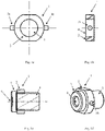
- Figures 1a and 1b show a schematic front view and a schematic cross-section view from the side of a heating device 1 according to a first embodiment of the invention.
- the heating device 1 essentially comprises a body 2 that comprises conductive material.
- the body 2 has the shape of a fastening nut and comprises an annular opening 4.
- two sections on two opposite ends of the essentially round body 2 could be flattened for using a wrench on the outer diameter of the body.
- the body 2 could also comprise all kinds of shapes on its outer periphery, for example the body 2 could comprise an essentially round, rectangular, and/or triangular shape.
- the body 2 could be injection-molded in one single piece as a plastic component comprising conductive material.
- conductive material such as graphite or nano-particles
- the body 2 could have an internal resistance that is sufficiently high for heating up the body 2 when a voltage is applied across the two electric contacts 3a, 3b that are in contact with the conductive mass of the body 2.
- the skilled person would know that values in the range of 50 to 500 ⁇ are appropriate for a voltage of 12 V, which is commonly used in motor vehicles.
- the voltage could be applied to the two electric contacts 3a, 3b by a voltage source (not shown in the figure) that is pulse width modulated to control the resulting heat so that the camera lens does not get adversely affected by overheating.
- the PWM signal could have a duty of 1 : x which can reduce the electrical input power by factor 'x'.
- the two electric contacts 3a, 3b are shown in the figures to be essentially located opposite each other.
- the electric contacts 3a, 3b are to be located deep inside the body 2, or more conductive material is to be distributed around the electric contacts 3a, 3b to increase the conductivity of the conductive material that is located around the electric contacts 3a, 3b.
- Figures 1c and 1d show a schematic cross-section view and an isometric view of a heating device 1 according the first embodiment of the invention installed on a camera 5.
- the cap of the lens holder 7 is made of essentially non-conductive plastic material, and the body 2 that comprises the conductive material can transfer heat via the cap of the lens holder 7 to the lens 6 of the camera 5.
- the skilled person would know, for the case in which the cap of the lens holder 7 comprises conductive material, such as for example metal, that an electrically insulating layer (not shown) could be arranged on the surface of the body 2 where the body 2 contacts the housing. For example, this could be done by arranging a thin foil comprising essentially isolating material between the two components.
- heat-conducting paste could be additionally arranged between the isolating material and the camera-housing to improve the heat transfer to the lens 6.
- the body 2 could also comprise a two-component plastic material comprising an electrically conducting layer that comprises the plastic and the conductive material, and a thermally conducting layer that is in contact with at least a part of the housing of the camera 5.
- the annular opening 4 comprises a thread that is adapted to interact with a corresponding thread along the circumference of the housing of the camera 5.
- the annular opening 4 could also comprises at least one protrusion or groove adapted to interact with a corresponding groove or protrusion on the housing of the camera 5 for connecting the heating device 1 to the camera 5.
- the heating device 1 could be also used for holding the lens 6 of the camera 5, which would make the lens holder 7 of the camera 5 that is shown in figures 1c and 1d redundant.
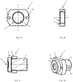
- FIGs 2a and 2b show a schematic front view and a schematic cross-section view from the side of a heating device 1' according to a second embodiment of the invention.
- the features of the heating device 1' could essentially correspond to the features of the heating device 1 that is shown in figures 1a-d , however the heating device 1' of the second embodiment distinguishes in that the electric contacts 3a', 3b' are arranged to extend essentially parallel to the housing of the camera 5'.
- the embodiment that is shown in figures 2a-d allows a more compact design as it can be best seen in figures 2c and 2d where the heating device 1' is installed on a camera 5'.
- FIG 3 shows a simplified exploded view of some of the components of a 180° fish eye lens in an exemplary use of the inventive heating device 1" according to a third embodiment of the invention.
- the features of the heating device 1" could essentially correspond to the features of the heating device 1 that is shown in figures 1a-d .
- the heating device 1" can be added directly behind the glass element of the lens 6", i.e. the heating device is directly attached to the lens of the camera.
- the heating device 1" has a form that is perfectly fitted to the form of the lens in order to provide sufficient heat without effecting the function of the lens 6".
- the heating device may be in form of a transparent coating, non-transparent coating, free standing film, paint, ink or any other form described herein. Additional parts are contacts (not shown; may be in the form of the embodiments described above) to enable power to reach the element. As power is also sent to a camera, this supply could also power up the heating device.
- the further features of the embodiment may be as disclosed for the first embodiment.
Landscapes
- Physics & Mathematics (AREA)
- Engineering & Computer Science (AREA)
- General Physics & Mathematics (AREA)
- Multimedia (AREA)
- Signal Processing (AREA)
- Aviation & Aerospace Engineering (AREA)
- Optics & Photonics (AREA)
- Electromagnetism (AREA)
- Studio Devices (AREA)
- Resistance Heating (AREA)
- Surface Heating Bodies (AREA)
Claims (14)
- Erwärmungsvorrichtung (1, 1', 1") für eine Linse (6, 6', 6") einer Kamera (5, 5'), wobei die Erwärmungsvorrichtung (1, 1', 1") umfasst:mindestens einen Körper (2, 2', 2"), der mindestens ein Matrixmaterial und mindestens ein leitendes Material umfasst, wobei das leitende Material in dem Matrixmaterial dispergiert ist, um eine leitende Masse auszubilden; undmindestens zwei elektrische Kontakte (3a, 3b, 3a', 3b'), die mit der leitenden Masse in Kontakt stehen, um eine elektrische Spannung an die leitende Masse anzulegen,dadurch gekennzeichnet, dassdie mindestens zwei elektrischen Kontakte (3a, 3b, 3a', 3b') an den Körper (2, 2', 2") angespritzt oder in den Körper (2, 2', 2") eingespritzt sind oderin der Nähe der Bereiche, in denen die beiden elektrischen Kontakte (3a, 3b, 3a', 3b') angeordnet sind, mehr leitendes Material verteilt ist als leitendes Material in dem übrigen Körper (2, 2', 2") verteilt ist.
- Erwärmungsvorrichtung (1, 1', 1") nach Anspruch 1, wobei
das leitende Material Kohlenstofffasern, Graphit, Kohlenstoff-Nanoröhren, Kohlenstoff-Nanohörner, Ruß, Graphen, Graphen-Nanoplättchen, Metallpartikel, leitende Polymere oder Mischungen daraus umfasst und in dem Matrixmaterial dispergiert ist, wobei das Matrixmaterial und das leitende Material vorzugsweise eine im Wesentlichen homogene leitende Masse ausbilden. - Erwärmungsvorrichtung (1, 1', 1") nach Anspruch 1, wobei,
falls in der Nähe der Bereiche, in denen die beiden elektrischen Kontakte (3a, 3b, 3a', 3b') angeordnet sind, mehr leitendes Material verteilt ist als leitendes Material in dem übrigen Körper (2, 2', 2") verteilt ist, der Körper (2, 2', 2") in der Form mindestens einer transparenten Beschichtung, einer nicht-transparenten Beschichtung, eines freistehenden Films oder eines Anstrichs vorliegt. - Erwärmungsvorrichtung (1, 1', 1") nach einem der vorangehenden Ansprüche, wobei die Erwärmungsvorrichtung (1, 1', 1") dazu ausgelegt ist, direkt auf das Glaselement der Linse (6, 6', 6") aufgebracht zu werden oder wobei die Erwärmungsvorrichtung dazu ausgelegt ist, auf einen nicht lichtdurchlässigen Teil der Linse (6, 6', 6") aufgebracht zu werden.
- Erwärmungsvorrichtung (1, 1') nach Anspruch 1 oder 2, wobei
der Körper (2, 2', 2") in Form eines massiven Verbundwerkstoffs vorliegt, wobei vorzugsweise die Erwärmungsvorrichtung (1, 1') dazu ausgelegt ist, abnehmbar an einem Gehäuse der Kamera (5, 5') angeordnet zu werden. - Erwärmungsvorrichtung (1, 1') nach Anspruch 5, wobei
der Körper (2, 2') eine im Wesentlichen ringförmige Öffnung (4, 4') zum abnehmbaren Anordnen des Körpers (2, 2') um das Gehäuse der Kamera (5, 5') herum umfasst, wobei der Körper (2, 2') vorzugsweise wie eine Befestigungsmutter geformt ist. - Erwärmungsvorrichtung (1, 1') nach Anspruch 6, wobei die ringförmige Öffnung (4, 4') Verbindungsmittel zum Verbinden des Körpers (2, 2') mit dem Gehäuse der Kamera (5, 5') umfasst.
- Erwärmungsvorrichtung (1, 1') nach Anspruch 7, wobei die Verbindungsmittel umfassen:ein Gewinde in der ringförmigen Öffnung (4, 4'), das dazu ausgelegt ist, mit einem entsprechenden Gewinde an dem Gehäuse der Kamera (5, 5') zusammenzuwirken, und/odermindestens eine(n) Vorsprung oder Nut, der/die dazu ausgelegt ist, mit einer/m entsprechenden Nut oder Vorsprung an dem Gehäuse der Kamera (5, 5') zusammenzuwirken.
- Erwärmungsvorrichtung (1, 1') nach Anspruch 8, wobeidas Gewinde in der ringförmigen Öffnung (4, 4') zumindest teilweise nichtleitendes Material zum Realisieren der beiden elektrischen Kontakte umfasst oderdie ringförmige Öffnung (4, 4') zwei Vorsprünge oder Nuten zum Realisieren der beiden elektrischen Kontakte umfasst.
- Erwärmungsvorrichtung (1, 1', 1") nach einem der vorangehenden Ansprüche, wobei die mindestens zwei elektrischen Kontakte (3a, 3b, 3a', 3b') im Wesentlichen einander gegenüberliegend an dem Körper (2, 2') angeordnet sind.
- Erwärmungsvorrichtung (1, 1') nach einem der Ansprüche 5 bis 10, umfassend mindestens eine elektrisch isolierende Schicht, die auf einer Oberfläche des Körpers (2, 2') angeordnet ist.
- System, umfassend:eine Erwärmungsvorrichtung (1, 1', 1") nach einem der vorangehenden Ansprüche, eine Kamera (5, 5') mit einer Linse (6, 6', 6") undmindestens eine Stromquelle, vorzugsweise eine Gleichspannungsquelle, die dazu ausgelegt ist, den beiden elektrischen Kontakten (3a, 3b, 3a', 3b') eine Spannung zuzuführen, wobei die Stromquelle vorzugsweise durch ein pulsweitenmoduliertes, pulse-width modulated - PWM, Signal steuerbar ist.
- Rückblickvorrichtung für ein Fahrzeug, vorzugsweise für ein Kraftfahrzeug, die mindestens eine Erwärmungsvorrichtung (1, 1') nach den Ansprüchen 1 bis 11 und/oder mindestens ein System nach Anspruch 12 umfasst.
- Fahrzeug, das mindestens eine Rückblickvorrichtung nach Anspruch 13 umfasst.
Priority Applications (1)
| Application Number | Priority Date | Filing Date | Title |
|---|---|---|---|
| EP21214098.2A EP3985960B1 (de) | 2017-03-06 | 2017-03-06 | Erwärmungsvorrichtung für eine kameralinse |
Applications Claiming Priority (2)
| Application Number | Priority Date | Filing Date | Title |
|---|---|---|---|
| EP17159418.7A EP3373571A1 (de) | 2017-03-06 | 2017-03-06 | Erwärmungsvorrichtung für eine kameralinse |
| EP21214098.2A EP3985960B1 (de) | 2017-03-06 | 2017-03-06 | Erwärmungsvorrichtung für eine kameralinse |
Related Parent Applications (1)
| Application Number | Title | Priority Date | Filing Date |
|---|---|---|---|
| EP17159418.7A Division EP3373571A1 (de) | 2017-03-06 | 2017-03-06 | Erwärmungsvorrichtung für eine kameralinse |
Publications (2)
| Publication Number | Publication Date |
|---|---|
| EP3985960A1 EP3985960A1 (de) | 2022-04-20 |
| EP3985960B1 true EP3985960B1 (de) | 2022-11-23 |
Family
ID=58448270
Family Applications (2)
| Application Number | Title | Priority Date | Filing Date |
|---|---|---|---|
| EP17159418.7A Withdrawn EP3373571A1 (de) | 2017-03-06 | 2017-03-06 | Erwärmungsvorrichtung für eine kameralinse |
| EP21214098.2A Active EP3985960B1 (de) | 2017-03-06 | 2017-03-06 | Erwärmungsvorrichtung für eine kameralinse |
Family Applications Before (1)
| Application Number | Title | Priority Date | Filing Date |
|---|---|---|---|
| EP17159418.7A Withdrawn EP3373571A1 (de) | 2017-03-06 | 2017-03-06 | Erwärmungsvorrichtung für eine kameralinse |
Country Status (3)
| Country | Link |
|---|---|
| US (1) | US10656501B2 (de) |
| EP (2) | EP3373571A1 (de) |
| CN (1) | CN108535939B (de) |
Families Citing this family (9)
| Publication number | Priority date | Publication date | Assignee | Title |
|---|---|---|---|---|
| US20190335074A1 (en) * | 2018-04-27 | 2019-10-31 | Cubic Corporation | Eliminating effects of environmental conditions of images captured by an omnidirectional camera |
| DE102018214108A1 (de) * | 2018-08-21 | 2020-02-27 | Conti Temic Microelectronic Gmbh | Temperaturregulierungselement und Sensoranordnung |
| CN109443383A (zh) * | 2018-10-31 | 2019-03-08 | 歌尔股份有限公司 | 飞行时间测距相机的标定方法、装置及可读存储介质 |
| EP3672362B2 (de) | 2018-12-18 | 2024-01-17 | Aptiv Technologies Limited | Heizvorrichtung |
| EP3672361B1 (de) * | 2018-12-18 | 2021-07-07 | Aptiv Technologies Limited | Heizvorrichtung |
| CN112198744B (zh) * | 2019-07-31 | 2021-10-22 | 宁波舜宇车载光学技术有限公司 | 光学装置及其应用 |
| CN113905472B (zh) * | 2020-07-07 | 2024-04-12 | 宁波舜宇车载光学技术有限公司 | 具有加热装置的镜片以及包括该镜片的镜头 |
| US20230011812A1 (en) * | 2021-07-06 | 2023-01-12 | Eterge Opto-Electronics Co., Ltd. | Optical imaging lens |
| EP4123357A1 (de) * | 2021-07-23 | 2023-01-25 | Ficosa Adas, S.L.U. | Linsenanordnung, kameramodul mit einer linsenanordnung für kraftfahrzeuge und herstellungsverfahren einer solchen linsenanordnung |
Family Cites Families (25)
| Publication number | Priority date | Publication date | Assignee | Title |
|---|---|---|---|---|
| JP4108787B2 (ja) * | 1997-07-14 | 2008-06-25 | オリンパス株式会社 | 電子内視鏡 |
| DE10033472A1 (de) | 2000-07-10 | 2002-01-24 | Metz Elektronik Gmbh | Optisches Gerät |
| ATE475263T1 (de) | 2003-05-22 | 2010-08-15 | Fico Mirrors Sa | Bilderfassungsmodul mit einer heizeinrichtung, mit der das umfeld eines kraftfahrzeugs überwacht wird |
| DE10340900A1 (de) | 2003-09-02 | 2005-03-24 | Valeo Schalter Und Sensoren Gmbh | Kameramodul mit heizbarer Abdeckscheibe |
| JP2005338433A (ja) * | 2004-05-27 | 2005-12-08 | Fuji Photo Film Co Ltd | カメラ |
| US7571589B2 (en) * | 2004-07-15 | 2009-08-11 | Storopack, Inc. | Apparatus for and method of producing and/or separating a string of interconnected packing cushions |
| DE102005001102B4 (de) | 2005-01-08 | 2021-04-29 | Carl Zeiss Microscopy Gmbh | Temperierbares Objektiv für Mikroskope |
| WO2008099156A2 (en) | 2007-02-12 | 2008-08-21 | Cambridge Mechatronics Limited | Shape memory alloy actuation apparatus |
| DE102008033316A1 (de) * | 2008-07-16 | 2010-01-21 | Siemens Aktiengesellschaft | Heizvorrichtung zur Beheizung einer Glasfläche, insbesondere eines Schutzglases einer Außenkamera |
| DE202008017509U1 (de) * | 2008-11-04 | 2009-10-15 | Neuhaus, Peter | Kameraschutzgehäuse |
| CN102162980A (zh) * | 2010-12-21 | 2011-08-24 | 天津市亚安科技电子有限公司 | 一种用于摄像机防护罩的视窗玻璃防结露系统 |
| CN202003121U (zh) * | 2011-02-01 | 2011-10-05 | 胜品电通股份有限公司 | 摄影机防护镜的除雾及除霜装置 |
| JP5800665B2 (ja) * | 2011-10-11 | 2015-10-28 | オリンパス株式会社 | 鏡枠ユニット、及び鏡枠ユニットを備えた内視鏡 |
| JP5315439B2 (ja) * | 2012-05-29 | 2013-10-16 | オリンパスイメージング株式会社 | 撮像ユニットおよび撮像装置 |
| WO2014122419A2 (en) * | 2013-02-05 | 2014-08-14 | Swansea University | Heating element |
| KR102206745B1 (ko) * | 2013-07-12 | 2021-02-03 | 경상대학교산학협력단 | 안토시아닌 및 gabab 수용체 작용제를 유효성분으로 포함하는 신경질환 치료제 |
| CN103412585B (zh) * | 2013-07-15 | 2015-09-23 | 航天东方红卫星有限公司 | 一种带主动控温的卫星相机热防护门系统 |
| CN103369225B (zh) * | 2013-08-08 | 2016-08-10 | 北京国网富达科技发展有限责任公司 | 防覆冰摄像机 |
| DE102013020894B3 (de) | 2013-12-11 | 2015-04-09 | Mekra Lang Gmbh & Co. Kg | Kamera mit Heizelement |
| KR101586397B1 (ko) * | 2013-12-31 | 2016-01-18 | (주)베바스토동희 홀딩스 | 차량속도감응형 선루프 초기화 장치 및 방법 |
| JP2016197513A (ja) * | 2015-04-02 | 2016-11-24 | 大日本印刷株式会社 | 照明装置用カバー、照明装置用ヒータ、照明装置 |
| JP2016219903A (ja) * | 2015-05-15 | 2016-12-22 | 株式会社東海理化電機製作所 | 撮像装置 |
| US10609262B2 (en) * | 2015-06-03 | 2020-03-31 | Lg Innotek Co., Ltd. | Lens barrel and camera module comprising same |
| CN204925588U (zh) * | 2015-07-30 | 2015-12-30 | 苏州宝时得电动工具有限公司 | 自动行走设备的摄像加热装置 |
| EP3340601B1 (de) * | 2015-08-17 | 2019-12-18 | LG Innotek Co., Ltd. | Kameramodul |
-
2017
- 2017-03-06 EP EP17159418.7A patent/EP3373571A1/de not_active Withdrawn
- 2017-03-06 EP EP21214098.2A patent/EP3985960B1/de active Active
-
2018
- 2018-03-06 US US15/913,060 patent/US10656501B2/en active Active
- 2018-03-06 CN CN201810184206.2A patent/CN108535939B/zh active Active
Also Published As
| Publication number | Publication date |
|---|---|
| EP3985960A1 (de) | 2022-04-20 |
| US20180252990A1 (en) | 2018-09-06 |
| EP3373571A1 (de) | 2018-09-12 |
| CN108535939B (zh) | 2021-07-20 |
| US10656501B2 (en) | 2020-05-19 |
| CN108535939A (zh) | 2018-09-14 |
Similar Documents
| Publication | Publication Date | Title |
|---|---|---|
| EP3985960B1 (de) | Erwärmungsvorrichtung für eine kameralinse | |
| EP3281397B1 (de) | Kameraheizelement für erweitertes fahrerassistenzsystem | |
| US10364954B2 (en) | Lens heating systems and methods for an LED lighting system | |
| CN112119351B (zh) | 透镜单元以及相机模块 | |
| US11042076B2 (en) | Camera module with heating element | |
| JP4908729B2 (ja) | 自動車用に好適な電気空気加熱装置 | |
| US10942330B2 (en) | Camera module | |
| CN109991797B (zh) | 加热装置及应用其的摄像器 | |
| EP3640730A1 (de) | Kameramodul für fahrzeug | |
| US11019689B2 (en) | Lens heating systems and methods for an LED lighting system | |
| CN101682940A (zh) | 膜内嵌模制塑料窗的电连接 | |
| US11480853B2 (en) | Heating device for a camera lens | |
| WO2008116539A2 (de) | Elektrisches gerät und verwendung | |
| EP2517316B1 (de) | Anschlussvorrichtung für den betrieb einer elektrischen vorrichtung | |
| CN112082136A (zh) | 用于led照明系统的透镜加热系统和方法 | |
| EP4333418A1 (de) | Kameramodul | |
| EP3751193B1 (de) | Linsenerwärmungssysteme und -verfahren für ein led-beleuchtungssystem | |
| CA3046569A1 (en) | Lens heating systems and methods for an led lighting system | |
| CN116406335A (zh) | 投影组件、显示系统及车辆 |
Legal Events
| Date | Code | Title | Description |
|---|---|---|---|
| PUAI | Public reference made under article 153(3) epc to a published international application that has entered the european phase |
Free format text: ORIGINAL CODE: 0009012 |
|
| STAA | Information on the status of an ep patent application or granted ep patent |
Free format text: STATUS: THE APPLICATION HAS BEEN PUBLISHED |
|
| STAA | Information on the status of an ep patent application or granted ep patent |
Free format text: STATUS: REQUEST FOR EXAMINATION WAS MADE |
|
| AC | Divisional application: reference to earlier application |
Ref document number: 3373571 Country of ref document: EP Kind code of ref document: P |
|
| AK | Designated contracting states |
Kind code of ref document: A1 Designated state(s): AL AT BE BG CH CY CZ DE DK EE ES FI FR GB GR HR HU IE IS IT LI LT LU LV MC MK MT NL NO PL PT RO RS SE SI SK SM TR |
|
| 17P | Request for examination filed |
Effective date: 20220325 |
|
| RBV | Designated contracting states (corrected) |
Designated state(s): AL AT BE BG CH CY CZ DE DK EE ES FI FR GB GR HR HU IE IS IT LI LT LU LV MC MK MT NL NO PL PT RO RS SE SI SK SM TR |
|
| GRAP | Despatch of communication of intention to grant a patent |
Free format text: ORIGINAL CODE: EPIDOSNIGR1 |
|
| STAA | Information on the status of an ep patent application or granted ep patent |
Free format text: STATUS: GRANT OF PATENT IS INTENDED |
|
| INTG | Intention to grant announced |
Effective date: 20220715 |
|
| GRAS | Grant fee paid |
Free format text: ORIGINAL CODE: EPIDOSNIGR3 |
|
| GRAA | (expected) grant |
Free format text: ORIGINAL CODE: 0009210 |
|
| STAA | Information on the status of an ep patent application or granted ep patent |
Free format text: STATUS: THE PATENT HAS BEEN GRANTED |
|
| AC | Divisional application: reference to earlier application |
Ref document number: 3373571 Country of ref document: EP Kind code of ref document: P |
|
| AK | Designated contracting states |
Kind code of ref document: B1 Designated state(s): AL AT BE BG CH CY CZ DE DK EE ES FI FR GB GR HR HU IE IS IT LI LT LU LV MC MK MT NL NO PL PT RO RS SE SI SK SM TR |
|
| REG | Reference to a national code |
Ref country code: GB Ref legal event code: FG4D |
|
| REG | Reference to a national code |
Ref country code: DE Ref legal event code: R079 Ref document number: 602017064065 Country of ref document: DE Free format text: PREVIOUS MAIN CLASS: H04N0005225000 Ipc: H04N0023000000 |
|
| REG | Reference to a national code |
Ref country code: CH Ref legal event code: EP |
|
| REG | Reference to a national code |
Ref country code: AT Ref legal event code: REF Ref document number: 1533868 Country of ref document: AT Kind code of ref document: T Effective date: 20221215 Ref country code: DE Ref legal event code: R096 Ref document number: 602017064065 Country of ref document: DE |
|
| REG | Reference to a national code |
Ref country code: IE Ref legal event code: FG4D |
|
| REG | Reference to a national code |
Ref country code: LT Ref legal event code: MG9D |
|
| REG | Reference to a national code |
Ref country code: DE Ref legal event code: R084 Ref document number: 602017064065 Country of ref document: DE Ref country code: NL Ref legal event code: MP Effective date: 20221123 |
|
| REG | Reference to a national code |
Ref country code: AT Ref legal event code: MK05 Ref document number: 1533868 Country of ref document: AT Kind code of ref document: T Effective date: 20221123 |
|
| PG25 | Lapsed in a contracting state [announced via postgrant information from national office to epo] |
Ref country code: SE Free format text: LAPSE BECAUSE OF FAILURE TO SUBMIT A TRANSLATION OF THE DESCRIPTION OR TO PAY THE FEE WITHIN THE PRESCRIBED TIME-LIMIT Effective date: 20221123 Ref country code: PT Free format text: LAPSE BECAUSE OF FAILURE TO SUBMIT A TRANSLATION OF THE DESCRIPTION OR TO PAY THE FEE WITHIN THE PRESCRIBED TIME-LIMIT Effective date: 20230323 Ref country code: NO Free format text: LAPSE BECAUSE OF FAILURE TO SUBMIT A TRANSLATION OF THE DESCRIPTION OR TO PAY THE FEE WITHIN THE PRESCRIBED TIME-LIMIT Effective date: 20230223 Ref country code: LT Free format text: LAPSE BECAUSE OF FAILURE TO SUBMIT A TRANSLATION OF THE DESCRIPTION OR TO PAY THE FEE WITHIN THE PRESCRIBED TIME-LIMIT Effective date: 20221123 Ref country code: FI Free format text: LAPSE BECAUSE OF FAILURE TO SUBMIT A TRANSLATION OF THE DESCRIPTION OR TO PAY THE FEE WITHIN THE PRESCRIBED TIME-LIMIT Effective date: 20221123 Ref country code: ES Free format text: LAPSE BECAUSE OF FAILURE TO SUBMIT A TRANSLATION OF THE DESCRIPTION OR TO PAY THE FEE WITHIN THE PRESCRIBED TIME-LIMIT Effective date: 20221123 Ref country code: AT Free format text: LAPSE BECAUSE OF FAILURE TO SUBMIT A TRANSLATION OF THE DESCRIPTION OR TO PAY THE FEE WITHIN THE PRESCRIBED TIME-LIMIT Effective date: 20221123 |
|
| PGFP | Annual fee paid to national office [announced via postgrant information from national office to epo] |
Ref country code: FR Payment date: 20230328 Year of fee payment: 7 |
|
| PG25 | Lapsed in a contracting state [announced via postgrant information from national office to epo] |
Ref country code: RS Free format text: LAPSE BECAUSE OF FAILURE TO SUBMIT A TRANSLATION OF THE DESCRIPTION OR TO PAY THE FEE WITHIN THE PRESCRIBED TIME-LIMIT Effective date: 20221123 Ref country code: PL Free format text: LAPSE BECAUSE OF FAILURE TO SUBMIT A TRANSLATION OF THE DESCRIPTION OR TO PAY THE FEE WITHIN THE PRESCRIBED TIME-LIMIT Effective date: 20221123 Ref country code: LV Free format text: LAPSE BECAUSE OF FAILURE TO SUBMIT A TRANSLATION OF THE DESCRIPTION OR TO PAY THE FEE WITHIN THE PRESCRIBED TIME-LIMIT Effective date: 20221123 Ref country code: IS Free format text: LAPSE BECAUSE OF FAILURE TO SUBMIT A TRANSLATION OF THE DESCRIPTION OR TO PAY THE FEE WITHIN THE PRESCRIBED TIME-LIMIT Effective date: 20230323 Ref country code: HR Free format text: LAPSE BECAUSE OF FAILURE TO SUBMIT A TRANSLATION OF THE DESCRIPTION OR TO PAY THE FEE WITHIN THE PRESCRIBED TIME-LIMIT Effective date: 20221123 Ref country code: GR Free format text: LAPSE BECAUSE OF FAILURE TO SUBMIT A TRANSLATION OF THE DESCRIPTION OR TO PAY THE FEE WITHIN THE PRESCRIBED TIME-LIMIT Effective date: 20230224 |
|
| PG25 | Lapsed in a contracting state [announced via postgrant information from national office to epo] |
Ref country code: NL Free format text: LAPSE BECAUSE OF FAILURE TO SUBMIT A TRANSLATION OF THE DESCRIPTION OR TO PAY THE FEE WITHIN THE PRESCRIBED TIME-LIMIT Effective date: 20221123 |
|
| P01 | Opt-out of the competence of the unified patent court (upc) registered |
Effective date: 20230616 |
|
| PG25 | Lapsed in a contracting state [announced via postgrant information from national office to epo] |
Ref country code: SM Free format text: LAPSE BECAUSE OF FAILURE TO SUBMIT A TRANSLATION OF THE DESCRIPTION OR TO PAY THE FEE WITHIN THE PRESCRIBED TIME-LIMIT Effective date: 20221123 Ref country code: RO Free format text: LAPSE BECAUSE OF FAILURE TO SUBMIT A TRANSLATION OF THE DESCRIPTION OR TO PAY THE FEE WITHIN THE PRESCRIBED TIME-LIMIT Effective date: 20221123 Ref country code: EE Free format text: LAPSE BECAUSE OF FAILURE TO SUBMIT A TRANSLATION OF THE DESCRIPTION OR TO PAY THE FEE WITHIN THE PRESCRIBED TIME-LIMIT Effective date: 20221123 Ref country code: DK Free format text: LAPSE BECAUSE OF FAILURE TO SUBMIT A TRANSLATION OF THE DESCRIPTION OR TO PAY THE FEE WITHIN THE PRESCRIBED TIME-LIMIT Effective date: 20221123 Ref country code: CZ Free format text: LAPSE BECAUSE OF FAILURE TO SUBMIT A TRANSLATION OF THE DESCRIPTION OR TO PAY THE FEE WITHIN THE PRESCRIBED TIME-LIMIT Effective date: 20221123 |
|
| REG | Reference to a national code |
Ref country code: DE Ref legal event code: R097 Ref document number: 602017064065 Country of ref document: DE |
|
| PG25 | Lapsed in a contracting state [announced via postgrant information from national office to epo] |
Ref country code: SK Free format text: LAPSE BECAUSE OF FAILURE TO SUBMIT A TRANSLATION OF THE DESCRIPTION OR TO PAY THE FEE WITHIN THE PRESCRIBED TIME-LIMIT Effective date: 20221123 Ref country code: AL Free format text: LAPSE BECAUSE OF FAILURE TO SUBMIT A TRANSLATION OF THE DESCRIPTION OR TO PAY THE FEE WITHIN THE PRESCRIBED TIME-LIMIT Effective date: 20221123 |
|
| PLBE | No opposition filed within time limit |
Free format text: ORIGINAL CODE: 0009261 |
|
| STAA | Information on the status of an ep patent application or granted ep patent |
Free format text: STATUS: NO OPPOSITION FILED WITHIN TIME LIMIT |
|
| PG25 | Lapsed in a contracting state [announced via postgrant information from national office to epo] |
Ref country code: MC Free format text: LAPSE BECAUSE OF FAILURE TO SUBMIT A TRANSLATION OF THE DESCRIPTION OR TO PAY THE FEE WITHIN THE PRESCRIBED TIME-LIMIT Effective date: 20221123 |
|
| REG | Reference to a national code |
Ref country code: CH Ref legal event code: PL |
|
| 26N | No opposition filed |
Effective date: 20230824 |
|
| PG25 | Lapsed in a contracting state [announced via postgrant information from national office to epo] |
Ref country code: SI Free format text: LAPSE BECAUSE OF FAILURE TO SUBMIT A TRANSLATION OF THE DESCRIPTION OR TO PAY THE FEE WITHIN THE PRESCRIBED TIME-LIMIT Effective date: 20221123 |
|
| REG | Reference to a national code |
Ref country code: BE Ref legal event code: MM Effective date: 20230331 |
|
| PG25 | Lapsed in a contracting state [announced via postgrant information from national office to epo] |
Ref country code: LU Free format text: LAPSE BECAUSE OF NON-PAYMENT OF DUE FEES Effective date: 20230306 |
|
| REG | Reference to a national code |
Ref country code: IE Ref legal event code: MM4A |
|
| PG25 | Lapsed in a contracting state [announced via postgrant information from national office to epo] |
Ref country code: LI Free format text: LAPSE BECAUSE OF NON-PAYMENT OF DUE FEES Effective date: 20230331 Ref country code: IE Free format text: LAPSE BECAUSE OF NON-PAYMENT OF DUE FEES Effective date: 20230306 Ref country code: CH Free format text: LAPSE BECAUSE OF NON-PAYMENT OF DUE FEES Effective date: 20230331 |
|
| PG25 | Lapsed in a contracting state [announced via postgrant information from national office to epo] |
Ref country code: BE Free format text: LAPSE BECAUSE OF NON-PAYMENT OF DUE FEES Effective date: 20230331 |
|
| PGFP | Annual fee paid to national office [announced via postgrant information from national office to epo] |
Ref country code: DE Payment date: 20240321 Year of fee payment: 8 Ref country code: GB Payment date: 20240322 Year of fee payment: 8 |