EP3985284B1 - Nutzfahrzeug - Google Patents
Nutzfahrzeug Download PDFInfo
- Publication number
- EP3985284B1 EP3985284B1 EP21201996.2A EP21201996A EP3985284B1 EP 3985284 B1 EP3985284 B1 EP 3985284B1 EP 21201996 A EP21201996 A EP 21201996A EP 3985284 B1 EP3985284 B1 EP 3985284B1
- Authority
- EP
- European Patent Office
- Prior art keywords
- speed
- speed change
- change process
- shifter
- increase
- Prior art date
- Legal status (The legal status is an assumption and is not a legal conclusion. Google has not performed a legal analysis and makes no representation as to the accuracy of the status listed.)
- Active
Links
Images



Classifications
-
- F—MECHANICAL ENGINEERING; LIGHTING; HEATING; WEAPONS; BLASTING
- F16—ENGINEERING ELEMENTS AND UNITS; GENERAL MEASURES FOR PRODUCING AND MAINTAINING EFFECTIVE FUNCTIONING OF MACHINES OR INSTALLATIONS; THERMAL INSULATION IN GENERAL
- F16H—GEARING
- F16H61/00—Control functions within control units of change-speed- or reversing-gearings for conveying rotary motion ; Control of exclusively fluid gearing, friction gearing, gearings with endless flexible members or other particular types of gearing
- F16H61/16—Inhibiting or initiating shift during unfavourable conditions , e.g. preventing forward-reverse shift at high vehicle speed, preventing engine overspeed
-
- F—MECHANICAL ENGINEERING; LIGHTING; HEATING; WEAPONS; BLASTING
- F16—ENGINEERING ELEMENTS AND UNITS; GENERAL MEASURES FOR PRODUCING AND MAINTAINING EFFECTIVE FUNCTIONING OF MACHINES OR INSTALLATIONS; THERMAL INSULATION IN GENERAL
- F16H—GEARING
- F16H59/00—Control inputs to control units of change-speed- or reversing-gearings for conveying rotary motion
- F16H59/36—Inputs being a function of speed
-
- F—MECHANICAL ENGINEERING; LIGHTING; HEATING; WEAPONS; BLASTING
- F16—ENGINEERING ELEMENTS AND UNITS; GENERAL MEASURES FOR PRODUCING AND MAINTAINING EFFECTIVE FUNCTIONING OF MACHINES OR INSTALLATIONS; THERMAL INSULATION IN GENERAL
- F16H—GEARING
- F16H59/00—Control inputs to control units of change-speed- or reversing-gearings for conveying rotary motion
- F16H59/48—Inputs being a function of acceleration
-
- F—MECHANICAL ENGINEERING; LIGHTING; HEATING; WEAPONS; BLASTING
- F16—ENGINEERING ELEMENTS AND UNITS; GENERAL MEASURES FOR PRODUCING AND MAINTAINING EFFECTIVE FUNCTIONING OF MACHINES OR INSTALLATIONS; THERMAL INSULATION IN GENERAL
- F16H—GEARING
- F16H61/00—Control functions within control units of change-speed- or reversing-gearings for conveying rotary motion ; Control of exclusively fluid gearing, friction gearing, gearings with endless flexible members or other particular types of gearing
- F16H61/02—Control functions within control units of change-speed- or reversing-gearings for conveying rotary motion ; Control of exclusively fluid gearing, friction gearing, gearings with endless flexible members or other particular types of gearing characterised by the signals used
- F16H61/0202—Control functions within control units of change-speed- or reversing-gearings for conveying rotary motion ; Control of exclusively fluid gearing, friction gearing, gearings with endless flexible members or other particular types of gearing characterised by the signals used the signals being electric
- F16H61/0204—Control functions within control units of change-speed- or reversing-gearings for conveying rotary motion ; Control of exclusively fluid gearing, friction gearing, gearings with endless flexible members or other particular types of gearing characterised by the signals used the signals being electric for gearshift control, e.g. control functions for performing shifting or generation of shift signal
- F16H61/0213—Control functions within control units of change-speed- or reversing-gearings for conveying rotary motion ; Control of exclusively fluid gearing, friction gearing, gearings with endless flexible members or other particular types of gearing characterised by the signals used the signals being electric for gearshift control, e.g. control functions for performing shifting or generation of shift signal characterised by the method for generating shift signals
-
- F—MECHANICAL ENGINEERING; LIGHTING; HEATING; WEAPONS; BLASTING
- F16—ENGINEERING ELEMENTS AND UNITS; GENERAL MEASURES FOR PRODUCING AND MAINTAINING EFFECTIVE FUNCTIONING OF MACHINES OR INSTALLATIONS; THERMAL INSULATION IN GENERAL
- F16H—GEARING
- F16H61/00—Control functions within control units of change-speed- or reversing-gearings for conveying rotary motion ; Control of exclusively fluid gearing, friction gearing, gearings with endless flexible members or other particular types of gearing
- F16H61/26—Generation or transmission of movements for final actuating mechanisms
- F16H61/28—Generation or transmission of movements for final actuating mechanisms with at least one movement of the final actuating mechanism being caused by a non-mechanical force, e.g. power-assisted
- F16H61/32—Electric motors , actuators or related electrical control means therefor
-
- F—MECHANICAL ENGINEERING; LIGHTING; HEATING; WEAPONS; BLASTING
- F16—ENGINEERING ELEMENTS AND UNITS; GENERAL MEASURES FOR PRODUCING AND MAINTAINING EFFECTIVE FUNCTIONING OF MACHINES OR INSTALLATIONS; THERMAL INSULATION IN GENERAL
- F16H—GEARING
- F16H3/00—Toothed gearings for conveying rotary motion with variable gear ratio or for reversing rotary motion
- F16H3/006—Toothed gearings for conveying rotary motion with variable gear ratio or for reversing rotary motion power being selectively transmitted by parallel flow paths, e.g. dual clutch transmissions
- F16H2003/008—Toothed gearings for conveying rotary motion with variable gear ratio or for reversing rotary motion power being selectively transmitted by parallel flow paths, e.g. dual clutch transmissions comprising means for selectively driving countershafts
-
- F—MECHANICAL ENGINEERING; LIGHTING; HEATING; WEAPONS; BLASTING
- F16—ENGINEERING ELEMENTS AND UNITS; GENERAL MEASURES FOR PRODUCING AND MAINTAINING EFFECTIVE FUNCTIONING OF MACHINES OR INSTALLATIONS; THERMAL INSULATION IN GENERAL
- F16H—GEARING
- F16H61/00—Control functions within control units of change-speed- or reversing-gearings for conveying rotary motion ; Control of exclusively fluid gearing, friction gearing, gearings with endless flexible members or other particular types of gearing
- F16H61/02—Control functions within control units of change-speed- or reversing-gearings for conveying rotary motion ; Control of exclusively fluid gearing, friction gearing, gearings with endless flexible members or other particular types of gearing characterised by the signals used
- F16H61/0202—Control functions within control units of change-speed- or reversing-gearings for conveying rotary motion ; Control of exclusively fluid gearing, friction gearing, gearings with endless flexible members or other particular types of gearing characterised by the signals used the signals being electric
- F16H61/0204—Control functions within control units of change-speed- or reversing-gearings for conveying rotary motion ; Control of exclusively fluid gearing, friction gearing, gearings with endless flexible members or other particular types of gearing characterised by the signals used the signals being electric for gearshift control, e.g. control functions for performing shifting or generation of shift signal
- F16H61/0213—Control functions within control units of change-speed- or reversing-gearings for conveying rotary motion ; Control of exclusively fluid gearing, friction gearing, gearings with endless flexible members or other particular types of gearing characterised by the signals used the signals being electric for gearshift control, e.g. control functions for performing shifting or generation of shift signal characterised by the method for generating shift signals
- F16H2061/0234—Adapting the ratios to special vehicle conditions
-
- F—MECHANICAL ENGINEERING; LIGHTING; HEATING; WEAPONS; BLASTING
- F16—ENGINEERING ELEMENTS AND UNITS; GENERAL MEASURES FOR PRODUCING AND MAINTAINING EFFECTIVE FUNCTIONING OF MACHINES OR INSTALLATIONS; THERMAL INSULATION IN GENERAL
- F16H—GEARING
- F16H61/00—Control functions within control units of change-speed- or reversing-gearings for conveying rotary motion ; Control of exclusively fluid gearing, friction gearing, gearings with endless flexible members or other particular types of gearing
- F16H61/12—Detecting malfunction or potential malfunction, e.g. fail safe ; Circumventing or fixing failures
- F16H2061/1244—Keeping the current state
-
- F—MECHANICAL ENGINEERING; LIGHTING; HEATING; WEAPONS; BLASTING
- F16—ENGINEERING ELEMENTS AND UNITS; GENERAL MEASURES FOR PRODUCING AND MAINTAINING EFFECTIVE FUNCTIONING OF MACHINES OR INSTALLATIONS; THERMAL INSULATION IN GENERAL
- F16H—GEARING
- F16H2306/00—Shifting
- F16H2306/24—Interruption of shift, e.g. if new shift is initiated during ongoing previous shift
Definitions
- the present invention relates to a working vehicle such as a tractor.
- Patent document 1 Japanese Unexamined Patent Publication No. 2019-6209 (Patent document 1) is known as a tractor which includes transmissions (transmission devices) such as a main transmission and an auxiliary transmission.
- Document EP0644362 presents another known example of control system for a working vehicle comprising a transmission device configured to transmit power from a prime mover to a traveling device and perform a speed change process to change a speed of the vehicle body; and further comprising an increase-in-speed detection device configured to detect an increase in speed of the vehicle body; and a speed change restraint unit configured such that, during the speed change process performed by the transmission device, when the increase in speed detected by the increase-in-speed detection device has become equal to or greater than a threshold, the speed change restraint unit stops the speed change process performed by the transmission device.
- the auxiliary transmission device is configured to change speed stages via a shifter, and speed change can be achieved by allowing the shifter to engage with a rotating body which is rotating.
- an object of the present invention is to provide a working vehicle capable of traveling in a stable manner even at the time of speed change.
- a working vehicle is defined in claim 1, and comprises: a vehicle body; a linkage device configured to link a working device to the vehicle body; a prime mover provided on the vehicle body; a traveling device configured to cause the vehicle body to travel; a transmission device configured to transmit power from the prime mover to the traveling device and perform a speed change process to change a speed of the vehicle body; an increase-in-speed detection device configured to detect an increase in speed of the vehicle body; and a speed change restraint unit configured such that, during the speed change process performed by the transmission device, when the increase in speed detected by the increase-in-speed detection device has become equal to or greater than a threshold, the speed change restraint unit stops the speed change process performed by the transmission device.
- the speed change restraint unit is configured such that, when the speed change process performed by the transmission device is a speed change process to reduce the speed of the vehicle body and the increase in speed after a start of the speed change process has become equal to or greater than the threshold, the speed change restraint unit stops the speed change process.
- the increase-in-speed detection device is configured to calculate, as the increase in speed, a difference in vehicle speed between a speed of the vehicle body at the start of the speed change process and a current speed of the vehicle body after the start of the speed change process.
- the transmission device includes a device configured to select a speed stage among multiple speed stages by movement of a shifter; and the speed change restraint unit is configured to stop the speed change process by moving a linkage member in a direction opposite to a direction in which the linkage member has been moved by the movement of the shifter, the linkage member being a member linked to the shifter.
- the linkage member is shiftable among a first position for maintaining the shifter in a neutral position, a second position for maintaining the shifter in a first slowdown position, and a third position for maintaining the shifter in a second slowdown position; and the speed change restraint unit includes a movement mechanism configured to: move the linkage member from the second position to the first position when the shifter is in the first slowdown position; and move the linkage member from the third position to the first position when the shifter is in the second slowdown position.
- the movement mechanism is shiftable among a stop position, one position, and another position on the opposite side of the stop position from the one position, the stop position corresponding to the first position of the linkage member, the one position corresponding to the second position of the linkage member, the other position corresponding to the third position of the linkage member; and the speed change restraint unit includes: a solenoid valve configured to shift the movement mechanism to the stop position, the one position, or the other position using hydraulic fluid; and a control device configured or programmed to control the solenoid valve.
- the control device is configured or programmed such that, when the increase in speed after the start of the speed change process has become equal to or greater than the threshold, the control device controls the solenoid valve to move the movement mechanism to the stop position.
- the speed change restraint unit is configured such that, when the increase in speed has become equal to or greater than the threshold, the speed change restraint unit stops the speed change process performed by the transmission device and then changes a speed stage of the transmission device back to a speed stage before the start of the speed change process.
- the transmission device includes an auxiliary transmission unit configured to select one of multiple speed stages.
- FIG. 4 is a side view of an embodiment of a working vehicle 1.
- the working vehicle 1 is a tractor.
- the working vehicle 1 is not limited to a tractor, and may be an agricultural machine (agricultural vehicle) such as a combine or a transplanting machine, a construction machine (construction vehicle) such as a loader working machine, or the like.
- the following description is based on the assumption that the front end of the tractor (working vehicle) 1 as viewed from an operator seated on an operator's seat 9 is “front” or “forward”, that the rear end of the tractor 1 as viewed from the operator is “rear” or “rearward”, that the left side of the tractor 1 as viewed from the operator is “left” or “leftward”, and that the right side of the tractor 1 as viewed from the operator is “right” or “rightward”.
- the following description is also based on the assumption that a horizontal direction orthogonal to a front-rear direction of the working vehicle 1 is "vehicle-width direction" (width direction of vehicle body).
- the tractor 1 includes a vehicle body 3, a linkage device 4, a transmission device 5, and a prime mover 8.
- the vehicle body 3 has a traveling device 7 and is configured to travel.
- the traveling device 7 is a device that includes front wheels 7F and rear wheels 7R.
- the front wheels 7F may be tire-type wheels or a crawler-type wheels.
- the rear wheels 7R may also be tire-type wheels or crawler-type wheels.
- the prime mover 8 is a diesel engine, an electric motor, or the like.
- the prime mover 8 is composed of a diesel engine.
- the transmission device 5 is configured to change driving forces for the traveling device 7 by performing a speed change process, and is configured to switch the traveling device 7 to a forward traveling state and to a rearward traveling state.
- the vehicle body 3 is provided with the operator's seat 9.
- the linkage device 4 is provided at the rear of the vehicle body 3.
- the linkage device 4 is a device which links, to the rear of the tractor 1, a working device (ground working machine, implement) 2 which performs work on an agricultural field (agricultural land) or the like.
- the working device 2 is a cultivator for cultivation, a fertilizer applicator for applying fertilizer, a pesticide applicator for applying pesticide, a harvester for harvesting, a mower for mowing grass or the like, a tedder for tedding grass or the like, a rake for raking grass or the like, a baler for shaping grass or the like, a trailer, or the like.
- the linkage device 4 also serves as, for example, a lifting and lowering device which is driven by an actuator such as a hydraulic cylinder to lift or lower the working device 2 (hereinafter may be referred to as "lifting and lowering device 4").
- the lifting and lowering device 4 is composed of a three-point linkage, and includes a lift arm 4a, a lower link 4b, a top link 4c, a lift rod 4d, and a lift cylinder 4e.
- the top link 4c and the lift rod 4d are configured to be linked to the working device 2.
- the working device 2 is configured to be lifted and lowered through the expansion and contraction of the lift cylinder 4e.
- the linkage device 4 is not limited to the above-described embodiment, and may be composed of, for example, a swing drawbar that pulls the working device 2.
- the transmission device 5 includes a travel forward/reverse switching unit 10, a main transmission unit 11, an auxiliary transmission unit 12, a PTO (power take-off) power transmission unit 13, and a front wheel power transmission unit 14.
- the travel forward/reverse switching unit 10 is a device that switches the direction of power transmitted from a crankshaft 15 of the prime mover 8 to a drive shaft 16 of a traveling system, i.e., the direction of rotation of the drive shaft 16, to the direction of normal rotation (forward) or the direction of reverse rotation (reverse).
- the travel forward/reverse switching unit 10 includes: a transmission shaft 20 that rotates as the crankshaft 15 rotates; a hydraulic clutch 21 that is shiftable between forward and reverse positions under hydraulic pressure; and a plurality of gears 22, 23, 24, and 25.
- the hydraulic clutch 21 When the hydraulic clutch 21 is in the forward position, power from the transmission shaft 20 is transmitted to the drive shaft 16 via the gears 25 and 26.
- the hydraulic clutch 21 When the hydraulic clutch 21 is in the reverse position, power from the transmission shaft 20 is transmitted to the drive shaft 16 via the gears 22, 23, 24, 25, and 26.
- the main transmission unit 11 is a transmission unit that receives the power from the drive shaft 16 to change speed stages.
- the main transmission unit 11 includes a first main switching unit 31, a second main switching unit 32, a third main switching unit 33, and a plurality of gears 34 to 44. Since the gears 34 to 44 differ in outside shape, the power transmitted by the gears 34 to 44 can be switched between different speed stages. Specifically, the power transmitted by the gears 34 to 41 is switched to any of the first to fourth stages, and the power transmitted by the gears 39 and 42 to 44 is switched to the first or second stage.
- the first main switching unit 31, the second main switching unit 32, and the third main switching unit 33 are each a hydraulic clutch that is shiftable among at least two opposite positions.
- the power from the drive shaft 16 is transmitted via the gears 34 and 41 to the gear 43 meshing with the gear 42 and to the gear 44 meshing with the gear 39.
- the power from the drive shaft 16 is transmitted to the gear 43 via the gears 35, 40, and 42 and to the gear 44 via the gears 35, 40, and 39.
- the power from the drive shaft 16 is transmitted to the gear 44 via the gears 36 and 39 and to the gear 43 via the gears 36, 39, and 42.
- the power from the drive shaft 16 is transmitted to the gear 43 via the gears 37, 38, and 42 and to the gear 44 via the gears 37, 38, and 39.
- the third main switching unit 33 When the third main switching unit 33 is in one of the opposite positions, the power transmitted to the gear 43 is transmitted to a transmission shaft 47. When the third main switching unit 33 is in the other of the opposite positions, the power transmitted to the gear 44 is transmitted to the transmission shaft 47.
- the auxiliary transmission unit 12 includes a creep unit 50, a first auxiliary switching unit 51, and a second auxiliary switching unit 52.
- the creep unit 50 is connected to the transmission shaft 47, and is shiftable among two opposite positions by the movement of a shifter. In the case where the creep unit 50 is in one of the opposite positions, the power from the transmission shaft 47 is transmitted via the shifter to the transmission shaft 57. In the case where the creep unit 50 is in the other of the opposite positions, the power from the transmission shaft 47 is transmitted via the gears 53 to 56 to the transmission shaft 57. That is, when the creep unit 50 is in one of the opposite positions, the rotation of the transmission shaft 47 is transmitted to the transmission shaft 57 without reduction. When the creep unit 50 is in the other of the opposite positions, the rotation of the transmission shaft 47 is reduced via the gears 53 to 56 and is transmitted to the transmission shaft 57.
- the first auxiliary switching unit 51 includes: a shifter 61 which rotates together with the transmission shaft 57 and which is movable along an axial direction; and a gear 62 which is rotatable relative to the transmission shaft 57.
- the shifter 61 when the shifter 61 has been moved to shift to one of the opposite positions (high-speed position) and the shifter 61 has engaged with a rotating body 67, the power from the transmission shaft 57 is transmitted to an output shaft 66 via gears 62, 63, 64, and 65.
- the gears 63 and 64 are rotatable together with a transmission shaft 80, and the gear 65 is rotatable together with the output shaft 66.
- the second auxiliary switching unit 52 includes gears 71, 72, 74, 76, and 77, rotating bodies 73 and 78, a transmitting body 75, and a shifter 79.
- the gear 71 rotates together with the transmission shaft 57.
- the gear 72 meshes with the gear 71.
- the rotating body 73 rotates together with the gear 72.
- the gear 74 is provided on the rotating body 73 and rotates together with the rotating body 73.
- the transmitting body 75 rotates relative to the transmission shaft 57, and rotates together with the gear 74.
- the gear 76 rotates together with the transmitting body 75.
- the gear 77 meshes with the gear 76.
- the rotating body 78 rotates as the gear 77 rotates.
- the shifter 79 rotates together with the transmission shaft 80 and is movable along the axial direction of the shifter 79.
- the speed at which the transmission shaft 57 is rotated by the power transmitted from the prime mover 8 is switched by the auxiliary transmission unit 12 to high speed (high-speed stage), medium speed (medium-speed stage), or low speed (low-speed stage), and the power transmitted to the transmission shaft 57 is transmitted to a rear wheel differential via the output shaft 66.
- the rear wheel differential is a device to rotate the rear wheels 7R.
- the PTO power transmission unit 13 includes a PTO rotation shaft 27, a switching mechanism 28, and a PTO shaft 29.
- the PTO rotation shaft 27 receives the power transmitted from the transmission shaft 20.
- the switching mechanism 28 switches between a state in which the switching mechanism 28 transmits the power from the PTO rotation shaft 27 and a state in which the switching mechanism 28 does not transmit the power from the PTO rotation shaft 27.
- the PTO shaft 29 receives the power transmitted from the switching mechanism 28.
- the front wheel power transmission unit 14 includes a transmission shaft 18 and a switching mechanism 19.
- the transmission shaft 18 receives the power transmitted from the output shaft 66 via gears.
- the power acting on the transmission shaft 18 is transmitted by the switching mechanism 19 toward the front wheels.
- the tractor 1 includes a control device 93.
- the control device 93 has connected thereto an operation member 88, with which an operator manually performs a speed change operation.
- the operation member 88 is a lever, a switch, or the like provided near the operator's seat 9, and is shiftable between a speedup position 88a and a slowdown position 88b.
- the auxiliary transmission unit 12 When the operation member 88 has been operated to move from a neutral position to the speedup position 88a (shifting up operation has been performed), the auxiliary transmission unit 12 performs a speed change process to increase speed (speed increasing process).
- the operation member 88 is operated to move from the neutral position to the speedup position 88a (shifting up operation is performed).
- a linkage member (shift fork) 87 fitted on the shifter 79 of the second auxiliary switching unit 52 moves from a medium-speed position (third position) 87M to a neutral position (first position) 87N
- a linkage member (shift fork) 85 fitted on the shifter 61 of the first auxiliary switching unit 51 moves from a neutral position 85N to a high-speed position 85H, thereby shifting the shifter 61 to the high-speed position H (high-speed stage) and shifting the auxiliary transmission unit 12 from medium-speed stage to high-speed stage.
- the linkage member (shift fork) 87 moves from a low-speed position (second position) 87L to the medium-speed position (third position) 87M, thereby shifting the shifter 79 to the medium-speed position M (medium-speed stage) and shifting the auxiliary transmission unit 12 from low-speed stage to medium-speed stage.
- the auxiliary transmission unit 12 When the operation member 88 has been operated to move from the neutral position to the slowdown position 88b (shifting down operation has been performed), the auxiliary transmission unit 12 performs a speed change process to reduce speed (speed reducing process).
- the operation member 88 is operated to move from the neutral position to the slowdown position 88b (shifting down operation is performed).
- the linkage member (shift fork) 85 moves from the high-speed position 85H to the neutral position 85N
- the linkage member (shift fork) 87 moves from the neutral position (first position) 87N to the medium-speed position (third position) 87M, thereby shifting the shifter 79 to the medium-speed position M and shifting the auxiliary transmission unit 12 from high-speed stage to medium-speed stage.
- the linkage member (shift fork) 87 moves from the medium-speed position (third position) 87M to the low-speed position (second position) 87L, thereby shifting the shifter 79 to the low-speed position L and shifting the auxiliary transmission unit 12 from high-speed stage to medium-speed stage.
- the tractor 1 includes a speed change restraint unit 90.
- the speed change restraint unit 90 is configured such that, during a speed change process performed by the transmission device 5, when an increase in speed of the vehicle body 3 has become equal to or greater than a threshold, the speed change restraint unit 90 stops the speed change process performed by the transmission device 5.
- the speed change restraint unit 90 is configured such that, when the speed change process performed by the transmission device 5 is a speed change process to reduce the speed of the vehicle body 3 and the increase in speed after the start of the speed change process has become equal to or greater than the threshold, the speed change restraint unit 9 stops the speed change process.
- the speed change restraint unit 90 includes a plurality of movement mechanisms 91, solenoid valves 92, and the control device 93.
- Each of the plurality of the movement mechanisms 91 is a mechanism configured to move the linkage members (shift forks) 85 and 87 using the pressure of hydraulic fluid.
- the plurality of movement mechanisms 91 include a first movement mechanism 91A and a second movement mechanism 91B.
- the first movement mechanism 91A includes a cylinder shiftable between a neutral position 101a and a high-speed position 101b.
- the first movement mechanism 91A (cylinder) is linked to the linkage member (shift fork) 85.
- the neutral position 101a corresponds to the neutral position 85N of the linkage member 85.
- the high-speed position 101b corresponds to the high-speed position 85H of the linkage member 85.
- the second movement mechanism 91B includes a shift cylinder shiftable among the following positions: a neutral position (stop position) 102a, a low-speed position (one position) 102b, and a medium-speed position (another position) 102c on the opposite side of the neutral position 102a from the low-speed position 102b.
- the second movement mechanism 91B is linked to the linkage member (shift fork) 87.
- the neutral position (stop position) 102a corresponds to the neutral position (first position) 87N of the linkage member 87.
- the low-speed position (one position) 102b corresponds to the low-speed position (second position) 87L of the linkage member 87.
- the medium-speed position (another position) 102c corresponds to the medium-speed position (third position) 87M of the linkage member 87.
- the shifter 79 is shifted from the neutral position N to the low-speed position (first slowdown position) L while the transmission device 5 is in its high-speed stage.
- the second movement mechanism 91B moves the linkage member 87 from the low-speed position (second position) 87L to the neutral position (first position) 87N.
- the shifter 79 is shifted from the neutral position N to the medium-speed position (second slowdown position) M while the transmission device 5 is in its high-speed stage.
- the second movement mechanism 91B moves the linkage member 87 from the medium-speed position (third position) 87M to the neutral position (first position) 87N.
- Each solenoid valve 92 is a valve which allows supply of hydraulic fluid to a corresponding movement mechanism 91 when it is open and which is connected to the movement mechanism 91 via a fluid passage.
- the solenoid valves 92 include a first switching valve 92a, a second switching valve 92b, a third switching valve 92c, a fourth switching valve 92d, and a fifth switching valve 92e.
- the first switching valve 92a is configured such that, when a solenoid thereof is energized by a control signal inputted from the control device 93, the first switching valve 92a allows supply of hydraulic fluid discharged from a hydraulic pump P1 to the first movement mechanism 91A, thereby shifting the first movement mechanism 91A to the neutral position 101a.
- the second switching valve 92b is configured such that, when a solenoid thereof is energized by a control signal inputted from the control device 93, the second switching valve 92b allows supply of hydraulic fluid discharged from the hydraulic pump P1 to the first movement mechanism 91A, thereby shifting the first movement mechanism 91A to the high-speed position 101b.
- the third switching valve 92c is configured such that, when a solenoid thereof is energized by a control signal inputted from the control device 93, the third switching valve 92c allows supply of hydraulic fluid discharged from the hydraulic pump P1 to the second movement mechanism 91B, thereby shifting the second movement mechanism 91B to the neutral position (stop position) 102a.
- the fourth switching valve 92d is configured such that, when a solenoid thereof is energized by a control signal inputted from the control device 93, the fourth switching valve 92d allows supply of hydraulic fluid discharged from the hydraulic pump P1 to the second movement mechanism 91B, thereby shifting the second movement mechanism 91B to the low-speed position (one position) 102b.
- the fifth switching valve 92e is configured such that, when a solenoid thereof is energized by a control signal inputted from the control device 93, the fifth switching valve 92e allows supply of hydraulic fluid discharged from the hydraulic pump P1 to the second movement mechanism 91B, thereby shifting the second movement mechanism 91B to the medium-speed position (another position) 102c.
- the control device 93 performs various types of controls concerning the tractor 1.
- the control device 93 has connected thereto: an operation detection device 94 configured to detect speed change operations; a speed change detection device 95 to detect speed change; and an increase-in-speed detection device 96 to detect an increase in speed of the vehicle body 3.
- the operation detection device 94 is a sensor to detect a speed change operation performed with the operation member 88. In the case where the operation member 88 has been operated to move from the neutral position to the speedup position 88a, the operation detection device 94 detects that the operation member 88 has been operated to increase speed (shifting up operation has been performed). In the case where the operation member 88 has been operated to move from the neutral position to the slowdown position 88b, the operation detection device 94 detects that the operation member 88 has been operated to reduce speed (shifting down operation has been performed).
- the increase-in-speed detection device 96 is a sensor configured to detect at least one of the following: the number of rotations of the front wheels 7F: the number of rotations of the rear wheels 7R; the number of rotations of a front axle on which the front wheels 7F are rotatably supported; and the number of rotations of a rear axle on which the rear wheels 7R are rotatably supported.
- the increase-in-speed detection device 96 convers the number of rotations of the front wheels 7F, the number of rotations of the rear wheels 7R, the number of rotations of the front axle, and/or the number of rotations of the rear axle into the speed of the vehicle body 3.
- the increase-in-speed detection device 96 calculates a difference in vehicle speed between the speed of the vehicle body 3 at the start of a speed change process and the current speed of the vehicle body 3 after the start of the speed change process (such a difference in vehicle speed is an increase in speed).
- the increase-in-speed detection device 96 retains the speed of the vehicle body 3 at the point in time in which the auxiliary transmission unit 12 was in its high-speed stage (high-speed position H) and in which speed change (speed change process) from the high-speed position H to the medium-speed position (second slowdown position) M was started (such a speed is "vehicle speed at the start of the speed change process"), and detects an increase in speed of the vehicle body 3 from the difference between the vehicle speed at the start of the speed change process and the current speed of the vehicle body 3 after the start of the speed change process (such a difference is "difference in vehicle speed").
- the increase-in-speed detection device 96 retains the speed of the vehicle body 3 at the point in time in which the auxiliary transmission unit 12 was in its medium-speed stage (medium-speed position M) and in which speed change (speed change process) from the medium-speed position M to the low-speed position (first slowdown position ) L was started (such a speed is "vehicle speed at the start of the speed change process"), and detects an increase in speed of the vehicle body 3 from the difference between the vehicle speed at the start of the speed change process and the current speed of the vehicle body 3 after the start of the speed change process (such a difference is "difference in vehicle speed").
- the speed change detection device 95 is, for example, a sensor to detect speed change performed by the transmission device 5. Specifically, the speed change detection device 95 detects whether speed change has been performed by the engagement between the shifter 61 or 79 and the rotating body 67, 73, or 78. When the shifter 61 has come into engagement with the rotating body 67, the speed change detection device 95 detects that a change to high-speed stage has been made (a change to high-speed stage has been completed). When the shifter 79 has come into engagement with the rotating body 73, the speed change detection device 95 detects that a change to low-speed stage has been made (a change to low-speed stage has been completed). When the shifter 79 has come into engagement with the rotating body 78, the speed change detection device 95 detects that a change to medium-speed stage has been made (a change to medium-speed stage has been completed).
- the control device 93 When the operation detection device 94 has detected a shifting down operation while the auxiliary transmission unit 12 was in its high-speed stage (such an operation is "first slowing down operation"), the control device 93 starts the following speed change process (first speed change process): the control device 93 outputs a control signal to the first switching valve 92a to shift the shifter 61 from the high-speed position H to the neutral position N; and outputs a control signal to the fifth switching valve 92e to shift the shifter 79 from the neutral position N to the medium-speed position M.
- first speed change process first speed change process
- the control device 93 refers to an increase in speed detected by the increase-in-speed detection device 96 after the start of the speed change process (first speed change process), and, when the increase in speed has become equal to or greater than a threshold, the control device 93 stops the first speed change process and performs a return process involving outputting a control signal to the second switching valve 92b and the third switching valve 92c to change the speed stage of the auxiliary transmission unit 12 back to high-speed stage.
- the control device 93 When the operation detection device 94 has detected a shifting down operation while the auxiliary transmission unit 12 was in its medium-speed stage (such an operation is "second slowing down operation"), the control device 93 starts the following speed change process (second speed change process): the control device 93 outputs a control signal to the third switching valve 92c and then outputs a control signal to the fourth switching valve 92d to shift the shifter 79 to the low-speed position L through the medium-speed position M and the neutral position N.
- second speed change process second speed change process
- the control device 93 refers to an increase in speed detected by the increase-in-speed detection device 96 after the start of the speed change process, and, when the increase in speed has become equal to or greater than a threshold, the control device 93 stops the second speed change process and performs a return process involving outputting a control signal to the fifth switching valve 92e to change the speed stage of the auxiliary transmission unit 12 back to medium-speed stage.
- the tractor 1 includes a notification device 99.
- the notification device 99 is, for example, a monitor, a speaker, and/or the like, and provides a notification of the speed change status of the transmission device 5.
- the notification device 99 is provided near the operator's seat 9, allowing the operator to understand the speed change status of the transmission device 5.
- speed change by the operation of the operation member 88 has been received (i.e., when the operation detection device 94 has detected the operation of changing speed stages)
- the notification device 99 provides a notification indicating that the speed change has been received, via, for example, sound outputted from the speaker and/or a symbol displayed on the monitor.
- the notification device 99 After the receipt of the speed change, when the speed change process has been stopped as described earlier, the notification device 99 provides a notification indicating that the speed change has been canceled, via sound outputted from the speaker and/or a symbol displayed on the monitor. Furthermore, in the case where the speed change has been canceled but the speed stage of the auxiliary transmission unit 12 has not been changed back to the original speed stage, the notification device 99 provides a notification indicating that the speed stage has not been changed back to the original speed stage, via, for example, sound outputted from the speaker and/or a symbol displayed on the monitor.
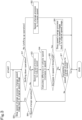
- FIG. 3 shows a flow of how the control device 93 operates at the time of speed change restraint.
- the control device 93 determines whether or not the operation detection device 94 has detected a speed change operation to reduce speed (slowing down operation, or shifting down operation) (S 1). For example, the control device 93 determines whether or not the operation detection device 94 has detected the operation of changing the speed stage from high-speed stage to medium-speed stage (first slowing down operation) or the operation of changing the speed stage from medium-speed stage to low-speed stage (second slowing down operation).
- the control device 93 performs a speed change process to increase speed (S2). For example, in the case of shifting up from medium-speed stage, the control device 93 outputs a control signal to the second switching valve 92b and the third switching valve 92c to shift the shifter 79 to the neutral position N and shift the shifter 61 to the high-speed position H. Alternatively, in the case of shifting up from low-speed stage, the control device 93 outputs a control signal to the fifth switching valve 92e to shift the shifter 79 to the medium-speed position M.
- the control device 93 performs a speed change process to reduce speed (S3).
- the control device 93 starts a speed change process (first speed change process) involving: outputting a control signal to the first switching valve 92a and the fifth switching valve 92e to shift the shifter 61 to the neutral position N and switch the shifter 79 to the medium-speed position M.
- the control device 93 starts a speed change process (second speed change process) involving outputting a control signal to the fourth switching valve 92d to shift the shifter 79 to the low-speed position L.
- the control device 93 retains the speed of the vehicle body 3 at the point in time in which the first speed change process or second speed change process was started (such a speed is "vehicle speed at the start of the first speed change process" or “vehicle speed at the start of the second speed change process"), and determines a difference in vehicle speed (increase in speed of the vehicle body 3) between the retained vehicle speed and the current speed of the vehicle body 3 (S4). Then, the control device 93 determines whether or not the increase in speed of the vehicle body 3 is equal to or greater than a threshold (S5).
- the control device 93 stops the first speed change process and changes the speed stage back to the speed stage before the first speed change process (performs a return process involving changing the speed stage back to the original speed stage) (S6).
- the control device 93 stops the second speed change process and changes the speed stage back to the speed stage before the second speed change process (performs a return process involving changing the speed stage back to the original speed stage) (S6).
- the control device 93 stops outputting the control signal to the first switching valve 92a and the fifth switching valve 92e to stop the first speed change process, and outputs a control signal to the second switching valve 92b and the third switching valve 92c to change the speed stage back to the original speed stage.
- the control device 93 stops outputting the control signal to the fourth switching valve 92d to stop the second speed change process, and outputs a control signal to the fifth switching valve 92e to change the speed stage back to the original speed stage.
- the control device 93 refers to the state of detection by the speed change detection device 95, and, in the case where the control device 93 has recognized the completion of shifting down from high-speed stage to medium-speed stage (completion of the speed change process) or the completion of shifting down from medium-speed stage to low-speed stage (completion of the speed change process) (Yes in S7), the control device 93 ends the speed change (shifting down) process.
- control device 93 determines whether or not a speed change operation (shifting up operation, shifting down operation) was performed during the speed change process (S8).
- the control device 93 stops the first speed change process and changes the speed stage back to the speed stage before the first speed change process (return process involving changing the speed stage back to the original speed stage).
- the control device 93 stops the second speed change process and changes the speed stage back to the speed stage before the second speed change process (return process involving changing the speed stage back to the original speed stage) (S9: stop the speed change process and change the speed stage back to the original speed stage). Then, the control device 93 returns processing to S1.
- control device 93 In the case where no speed change operation was performed during the speed change process (No in S8), the control device 93 returns processing to S3 to continue the speed change process to reduce speed. Note that the control device 93 returns processing to S1 also in the case where a speed change operation is performed in any of the steps S3 to S6.
- the first speed change process is started regardless of the speed of the vehicle body 3; however, the following configuration may be employed instead: the control device 93 starts the first speed change process when the speed of the vehicle body 3 is equal to or less than a first upper limit and the first slowing down operation has been detected; and the control device 93 does not start the first speed change process when the speed of the vehicle body 3 has exceeded the first upper limit.
- the following configuration may also be employed: the control device 93 starts the second speed change process when the vehicle speed is equal to or less than a second upper limit and the second slowing down operation has been detected; and the control device 93 does not start the second speed change process when the vehicle speed has exceeded the second upper limit.
- the first upper limit is set to be greater than the second upper limit.
- a working vehicle 1 comprises: a vehicle body 3; a linkage device 4 configured to link a working device 2 to the vehicle body 3; a prime mover 8 provided on the vehicle body 3; a traveling device 7 configured to cause the vehicle body 3 to travel; a transmission device 5 configured to transmit power from the prime mover 8 to the traveling device 7 and perform a speed change process to change a speed of the vehicle body 3; an increase-in-speed detection device 96 configured to detect an increase in speed of the vehicle body 3; and a speed change restraint unit 90 configured such that, during the speed change process performed by the transmission device 5, when the increase in speed detected by the increase-in-speed detection device 96 has become equal to or greater than a threshold, the speed change restraint unit 90 stops the speed change process performed by the transmission device 5.
- the speed change restraint unit 90 is configured such that, when the speed change process performed by the transmission device 5 is a speed change process to reduce the speed of the vehicle body 3 and the increase in speed after a start of the speed change process has become equal to or greater than the threshold, the speed change restraint unit 90 stops the speed change process. This achieves the following: under the circumstances in which the working vehicle 1 is traveling down a slope with a towed working device 2 such as a trailer, in the case where the speed change process to reduce the speed of the vehicle body 3 would result in acceleration of the vehicle body 3, the speed change process is stopped and thereby the working vehicle 1 is prevented from being pushed forward by the trailer or the like.
- the increase-in-speed detection device 96 is configured to calculate, as the increase in speed, a difference in vehicle speed between a speed of the vehicle body 3 at the start of the speed change process and a current speed of the vehicle body 3 after the start of the speed change process. This makes it possible to easily determine an increase in speed of the vehicle body 3.
- the transmission device 5 includes a device configured to select a speed stage among multiple speed stages by movement of a shifter 61 or 79; and the speed change restraint unit 90 is configured to stop the speed change process by moving a linkage member 85 or 87 in a direction opposite to a direction in which the linkage member 85 or 87 has been moved by the movement of the shifter 61 or 79, the linkage member 85 or 87 being a member linked to the shifter 61 or 79.
- This achieves the following: in the case where the time taken for speed change by the shifter 61 or 79 is relatively long, when the vehicle body 3 would accelerate, the speed change process is stopped and thereby stable travel is achieved.
- the linkage member 87 is shiftable among a first position 87N for maintaining the shifter 79 in a neutral position N, a second position 87L for maintaining the shifter 79 in a first slowdown position L, and a third position 87M for maintaining the shifter 79 in a second slowdown position M; and the speed change restraint unit 90 includes a movement mechanism 91 (91B) configured to: move the linkage member 87 from the second position 87L to the first position 87N when the shifter 79 is in the first slowdown position L; and move the linkage member 87 from the third position 87M to the first position 87N when the shifter 79 is in the second slowdown position M.
- a movement mechanism 91B configured to: move the linkage member 87 from the second position 87L to the first position 87N when the shifter 79 is in the first slowdown position L; and move the linkage member 87 from the third position 87M to the first position 87N when the shifter 79 is in the second
- the movement mechanism 91 (91B) is shiftable among a stop position 102a, one position 102b, and another position 102c on the opposite side of the stop position 120a from the one position 102b, the stop position 102a corresponding to the first position 87N of the linkage member 87, the one position 102b corresponding to the second position 87L of the linkage member 87, the other position 102c corresponding to the third position 87M of the linkage member 87; and the speed change restraint unit 90 includes: a solenoid valve 92 configured to shift the movement mechanism 91 (91B) to the stop position 102a, the one position 102b, or the other position 102c using hydraulic fluid; and a control device 93 configured or programmed to control the solenoid valve 92.
- control device 93 controls the solenoid valve 92 to shift the movement mechanism 91 (91B) from the one position 102b to the stop position 102a or from the other position 102c to the stop position 102a, thereby making it possible to quickly stop the speed reduction with the shifter 79.
- the control device 93 is configured or programmed such that, when the increase in speed after the start of the speed change process has become equal to or greater than the threshold, the control device 93 controls the solenoid valve 92 to move the movement mechanism 91 (91B) to the stop position 102a. This makes it possible to smoothly move the movement mechanism 91 (91B) to the stop position 102a with the solenoid valve 92.
- the speed change restraint unit 90 is configured such that, when the increase in speed has become equal to or greater than the threshold, the speed change restraint unit 90 stops the speed change process performed by the transmission device 5 and then changes a speed stage of the transmission device 5 back to a speed stage before the start of the speed change process. This makes it possible to eliminate or reduce the likelihood that the vehicle body 3 will accelerate at the time of speed change, and possible to achieve more stable travel.
- the transmission device 5 includes an auxiliary transmission unit 12 configured to select one of multiple speed stages. This allows the working vehicle 1 to travel stably even in the case where vehicle speed (speed) is adjusted while auxiliary speed change is performed or in the case where auxiliary speed change is performed according to the slope of an agricultural field or a road.
Landscapes
- Engineering & Computer Science (AREA)
- General Engineering & Computer Science (AREA)
- Mechanical Engineering (AREA)
- Control Of Transmission Device (AREA)
Claims (7)
- Arbeitsfahrzeug (1), umfassend:eine Fahrzeugkarosserie (3),eine Anlenkungsvorrichtung (4), die dazu ausgestaltet ist, eine Arbeitsvorrichtung (2) an die Fahrzeugkarosserie (3) anzulenken,einen Antriebsmotor (8), der an der Fahrzeugkarosserie (3) vorgesehen ist,eine Fahrvorrichtung (7), die dazu ausgestaltet ist, die Fahrzeugkarosserie (3) zum Fahren zu veranlassen,eine Getriebevorrichtung (5), die dazu ausgestaltet, Energie von dem Antriebsmotor (8) an die Fahrvorrichtung (7) zu übertragen und einen Geschwindigkeitsänderungs-Prozess durchzuführen, um eine Geschwindigkeit der Fahrzeugkarosserie (3) zu verändern,eine Geschwindigkeitszunahme-Erfassungsvorrichtung (96), die dazu ausgestaltet ist, eine Zunahme der Geschwindigkeit der Fahrzeugkarosserie (3) zu erfassen, undeine Geschwindigkeitsänderungs-Beschränkungseinheit (90), die so ausgestaltet ist, dass während des Geschwindigkeitsänderungs-Prozesses, der von der Getriebevorrichtung (5) durchgeführt wird, wenn die Zunahme der Geschwindigkeit, die von der Geschwindigkeitszunahme-Erfassungsvorrichtung (96) erfasst wird, gleich oder größer als eine Schwelle geworden ist, die Geschwindigkeitsänderungs-Beschränkungseinheit (90) den Geschwindigkeitsänderungs-Prozess, der von der Getriebevorrichtung (5) durchgeführt wird, stoppt und anschließend einen Rückkehrprozess durchführt, um eine Geschwindigkeitsstufe der Getriebevorrichtung (5) zurück auf eine Geschwindigkeitsstufe vor dem Start des Geschwindigkeitsänderungs-Prozesses zu ändern.
- Arbeitsfahrzeug (1) nach Anspruch 1, wobei die Geschwindigkeitsänderungs-Beschränkungseinheit (90) so ausgestaltet ist, dass wenn der Geschwindigkeitsänderungs-Prozess, der von der Getriebevorrichtung (5) gestartet wurde, ein Geschwindigkeitsänderungs-Prozess ist, um die Geschwindigkeit der Fahrzeugkarosserie (3) zu verringern, und wenn die Zunahme der Geschwindigkeit nach einem Start des Geschwindigkeitsänderungs-Prozesses gleich oder größer als die Schwelle geworden ist, die Geschwindigkeitsänderungs-Beschränkungseinheit (90) den Geschwindigkeitsänderungs-Prozess stoppt und anschließend den Rückkehrprozess durchführt.
- Arbeitsfahrzeug (1) nach Anspruch 2, wobei die Geschwindigkeitszunahme-Erfassungsvorrichtung (96) dazu ausgestaltet ist, als die Zunahme der Geschwindigkeit eine Differenz in der Fahrzeuggeschwindigkeit zwischen einer Geschwindigkeit der Fahrzeugkarosserie (3) bei dem Start des Geschwindigkeitsänderungs-Prozesses und einer aktuellen Geschwindigkeit der Fahrzeugkarosserie (3) nach dem Start des Geschwindigkeitsänderungs-Prozesses zu berechnen.
- Arbeitsfahrzeug (1) nach einem der Ansprüche 1 bis 3, wobei:die Getriebevorrichtung (5) eine Vorrichtung beinhaltet, die dazu ausgestaltet ist, eine Geschwindigkeitsstufe aus mehreren Geschwindigkeitsstufen durch Bewegung von zumindest einem von zwei Schalthebeln (61, 79) auszuwählen, unddie Geschwindigkeitsänderungs-Beschränkungseinheit (90) dazu ausgestaltet ist, wenn die Zunahme der Geschwindigkeit während des Geschwindigkeitsänderungs-Prozesses, der von der Getriebevorrichtung (5) durchgeführt wird, gleich oder größer als die Schwelle geworden ist, den Geschwindigkeitsänderungs-Prozess zu stoppen und anschließend den Rückkehrprozess durchzuführen, indem zumindest eines von zwei Anlenkungselementen (85, 87) in einer Richtung bewegt wird, die einer Richtung entgegengesetzt ist, in welcher das zumindest eine Anlenkungselement (85, 87) durch die Bewegung des zumindest einen Schalthebels (61, 79) bewegt worden ist, wobei die Anlenkungselemente (85, 87) Elemente sind, die an die Schalthebel (61, 79) angelenkt sind.
- Arbeitsfahrzeug (1) nach Anspruch 4, wobei:das zumindest eine Anlenkungselement (87) an den zumindest einen Schalthebel (79) angelenkt ist und zwischen einer ersten Stellung (87N) zum Halten des zumindest einen Schalthebels (79) in einer Neutralstellung (N), einer zweiten Stellung (87L) zum Halten des zumindest einen Schalthebels (79) in einer ersten Verlangsamungsstellung (L), und einer dritten Stellung (87M) zum Halten des zumindest einen Schalthebels (79) in einer zweiten Verlangsamungsstellung (M) schaltbar ist, unddie Geschwindigkeitsänderungs-Beschränkungseinheit (90) einen zweiten Bewegungsmechanismus (91B) beinhaltet, der dazu ausgestaltet ist:das zumindest eine Anlenkungselement (87) aus der zweiten Stellung (87L) in die erste Stellung (87N) zu bewegen, wenn die Zunahme der Geschwindigkeit gleich oder größer als die Schwelle geworden ist, während eines zweiten Geschwindigkeitsänderungs-Prozesses, um den zumindest einen Schalthebel (79) in die erste Verlangsamungsstellung (L) zu schalten, unddas zumindest eine Anlenkungselement (87) aus der dritten Stellung (87M) in die erste Stellung (87N) zu bewegen, wenn die Zunahme der Geschwindigkeit gleich oder größer als die Schwelle geworden ist, während eines ersten Geschwindigkeitsänderungs-Prozesses, um den zumindest einen Schalthebel (79) in die zweite Verlangsamungsstellung (M) zu schalten.
- Arbeitsfahrzeug (1) nach Anspruch 5, wobei:ein Anlenkungselement (85), welches das andere der Anlenkungselemente (85, 87) ist, an einen Schalthebel (61) angelenkt ist, welcher der andere der Schalthebel (61, 79) ist, und zwischen einer neutralen Stellung (85N) und einer Hochgeschwindigkeitsstellung (85H) schaltbar ist, um den anderen Schalthebel (61) in eine Hochgeschwindigkeitsstellung (H) zu schalten,die Geschwindigkeitsänderungs-Beschränkungseinheit (90) einen ersten Bewegungsmechanismus (91A) beinhaltet, der zwischen einer neutralen Stellung (101a), welche der neutralen Stellung (85N) des anderen Anlenkungselements (85) entspricht, und einer Hochgeschwindigkeitsstellung (101b), welche der Hochgeschwindigkeitsstellung (85H) des anderen Anlenkungselements (85) entspricht, schaltbar ist,der zweite Bewegungsmechanismus (91B) zwischen einer Stoppstellung (102a), einer Stellung (102b) und einer weiteren Stellung (102c) auf der der Stoppstellung (120a) in Bezug auf die eine Stellung (102b) entgegengesetzten Seite schaltbar ist, wobei die Stoppstellung (102a) der ersten Stellung (87N) des zumindest einen Anlenkungselements (87) entspricht, die eine Stellung (102b) der zweiten Stellung (87L) des Anlenkungselements (87) entspricht, die andere Stellung (102c) der dritten Stellung (87M) des zumindest einen Anlenkungselements (87) entspricht,die Geschwindigkeitsänderungs-Beschränkungseinheit (90) Magnetventile (92) und eine Steuervorrichtung (93) beinhaltet,wobei die Magnetventile (92) beinhaltenein erstes Schaltventil (92a), um den ersten Bewegungsmechanismus (91A) unter Verwendung von Hydraulikfluid in die neutrale Stellung (101a) zu schalten,ein zweites Schaltventil (92b), um den ersten Bewegungsmechanismus (91A) unter Verwendung von Hydraulikfluid in die Hochgeschwindigkeitsstellung (101b) zu schalten,ein drittes Schaltventil (92c), um den zweiten Bewegungsmechanismus (91B) unter Verwendung von Hydraulikfluid in die Stoppstellung (102a) zu schalten,ein viertes Schaltventil (92d), um den zweiten Bewegungsmechanismus (91B) unter Verwendung von Hydraulikfluid in die eine Stellung (102b) zu schalten, undein fünftes Schaltventil (92e), um den zweiten Bewegungsmechanismus (91B) unter Verwendung von Hydraulikfluid in die andere Stellung (102c) zu schalten, unddie Steuervorrichtung (93) dazu ausgestaltet oder programmiert ist, das erste bis fünfte Schaltventil (92a, 92b, 92c, 92d, 92e) zu steuern.
- Arbeitsfahrzeug (1) nach Anspruch 6, wobeidie Getriebevorrichtung (5) eine Hilfs-Getriebeeinheit (12) beinhaltet, die dazu ausgestaltet ist, eine der folgenden Geschwindigkeitsstufen auszuwählen: eine Hochgeschwindigkeitsstufe, eine mittlere Geschwindigkeitsstufe, und eine niedrige Geschwindigkeitsstufe, unddie Steuervorrichtung (93) so ausgestaltet oder programmiert ist, dasswenn die Zunahme der Geschwindigkeit während des ersten Geschwindigkeitsänderungs-Prozesses, der das Schalten des Schalthebels (61) aus der Hochgeschwindigkeitsstellung (H) in die neutrale Stellung (N) und das Schalten des Schalthebels (79) aus der neutralen Stellung (N) in die zweite Verlangsamungsstellung (M) einschließt, um die Hilfs-Getriebeeinheit (12) aus der Hochgeschwindigkeitsstufe in die mittlere Geschwindigkeitsstufe zu schalten, gleich oder größer als die Schwelle geworden ist, die Steuervorrichtung (93) das Ausgeben eines Steuersignals an das erste Schaltventil (92a) und das fünfte Schaltventil (92e) stoppt, um den ersten Geschwindigkeitsänderungs-Prozess zu stoppen, und ein Steuersignal an das zweite Schaltventil (92b) und das dritte Schaltventil (92c) ausgibt, um den Rückkehrprozess durchzuführen, um eine Geschwindigkeitsstufe der Hilfs-Getriebeeinheit (12) zurück auf die Hochgeschwindigkeitsstufe zu ändern, undwenn die Zunahme der Geschwindigkeit während des zweiten Geschwindigkeitsänderungs-Prozesses, der das Schalten des Schalthebels (79) von der zweiten Verlangsamungsstellung (M) in die erste Verlangsamungsstellung (L) durch die neutrale Stellung (N) einschließt, um die Hilfs-Getriebeeinheit (12) von der mittleren Geschwindigkeitsstufe auf die niedrige Geschwindigkeitsstufe zu schalten, gleich oder größer als die Schwelle geworden ist, die Steuervorrichtung (93) das Ausgeben eines Steuersignals an das dritte Schaltventil (92c) und das vierte Schaltventil (92d) stoppt, um den zweiten Geschwindigkeitsänderungs-Prozess zu stoppen, und ein Steuersignal an das fünfte Schaltventil (92e) ausgibt, um den Rückkehrprozess durchzuführen, um die Geschwindigkeitsstufe der Hilfs-Getriebeeinheit (12) zurück auf die mittlere Geschwindigkeitsstufe zu ändern.
Applications Claiming Priority (1)
| Application Number | Priority Date | Filing Date | Title |
|---|---|---|---|
| JP2020172798A JP7413226B2 (ja) | 2020-10-13 | 2020-10-13 | 作業車両 |
Publications (2)
| Publication Number | Publication Date |
|---|---|
| EP3985284A1 EP3985284A1 (de) | 2022-04-20 |
| EP3985284B1 true EP3985284B1 (de) | 2023-05-10 |
Family
ID=78087220
Family Applications (1)
| Application Number | Title | Priority Date | Filing Date |
|---|---|---|---|
| EP21201996.2A Active EP3985284B1 (de) | 2020-10-13 | 2021-10-11 | Nutzfahrzeug |
Country Status (3)
| Country | Link |
|---|---|
| US (1) | US11674593B2 (de) |
| EP (1) | EP3985284B1 (de) |
| JP (1) | JP7413226B2 (de) |
Families Citing this family (1)
| Publication number | Priority date | Publication date | Assignee | Title |
|---|---|---|---|---|
| US12018750B2 (en) * | 2022-11-17 | 2024-06-25 | Kubota Corporation | Work vehicle |
Family Cites Families (7)
| Publication number | Priority date | Publication date | Assignee | Title |
|---|---|---|---|---|
| JP2913481B2 (ja) * | 1989-05-19 | 1999-06-28 | アイシン精機株式会社 | 自動変速機の油圧制御装置 |
| US5429559A (en) * | 1993-09-22 | 1995-07-04 | Eaton Corporation | Forced engagement logic |
| JP3542066B2 (ja) | 1998-09-21 | 2004-07-14 | 株式会社クボタ | 農用トラクタと農用トラクタのクラッチ制御方法 |
| US6385520B1 (en) * | 2000-08-10 | 2002-05-07 | Ford Global Technologies, Inc. | Control strategy and method for independently controlling friction element actuators for an automatic transmission |
| JP6203060B2 (ja) * | 2014-01-15 | 2017-09-27 | 株式会社小松製作所 | 作業車両及びその制御方法 |
| US10281030B2 (en) * | 2016-07-27 | 2019-05-07 | Allison Transmission, Inc. | Manual shifting control system and method for multi-speed automatic transmission |
| JP6807808B2 (ja) | 2017-06-22 | 2021-01-06 | 株式会社クボタ | 作業車用トランスミッション及びこれを備えた作業車 |
-
2020
- 2020-10-13 JP JP2020172798A patent/JP7413226B2/ja active Active
-
2021
- 2021-10-07 US US17/496,333 patent/US11674593B2/en active Active
- 2021-10-11 EP EP21201996.2A patent/EP3985284B1/de active Active
Also Published As
| Publication number | Publication date |
|---|---|
| US11674593B2 (en) | 2023-06-13 |
| JP2022064201A (ja) | 2022-04-25 |
| EP3985284A1 (de) | 2022-04-20 |
| JP7413226B2 (ja) | 2024-01-15 |
| US20220112950A1 (en) | 2022-04-14 |
Similar Documents
| Publication | Publication Date | Title |
|---|---|---|
| KR100524564B1 (ko) | 트랜스미션용 제어 장치 | |
| US11800828B2 (en) | Working vehicle | |
| US11660959B2 (en) | Method of operating an agricultural vehicle and a transmission arrangement for an agricultural vehicle | |
| US6138528A (en) | Agricultural tractor | |
| US11674593B2 (en) | Working vehicle | |
| US5992260A (en) | Operating device for a working vehicle | |
| US12419206B2 (en) | Working machine | |
| JP4025528B2 (ja) | ロータリー耕耘作業機を備えたトラクタの走行制御装置 | |
| JP5138392B2 (ja) | 農作業機 | |
| US11268614B2 (en) | Working vehicle | |
| JP2001122148A (ja) | 管理作業車 | |
| JP3680451B2 (ja) | 作業車両の自動変速制御装置 | |
| JP3917898B2 (ja) | 作業車の走行変速構造 | |
| JP2016215723A (ja) | 作業車両 | |
| JP7527861B2 (ja) | 作業車両 | |
| EP4691883A1 (de) | Arbeitsfahrzeug | |
| JP4171188B2 (ja) | 作業車両の車速制御機構 | |
| JP2006199289A (ja) | コンバイン | |
| JPH09240297A (ja) | 作業車の走行伝動構造 | |
| JP2025112785A (ja) | トランスミッションおよび作業車両 | |
| JP2001039331A (ja) | 移動農機 | |
| WO2026033668A1 (ja) | 作業車両 | |
| JP2006283982A (ja) | 作業車の走行変速構造 | |
| JP3190986B2 (ja) | 移動農機 | |
| JPH078018A (ja) | コンバインの自動操向装置 |
Legal Events
| Date | Code | Title | Description |
|---|---|---|---|
| PUAI | Public reference made under article 153(3) epc to a published international application that has entered the european phase |
Free format text: ORIGINAL CODE: 0009012 |
|
| STAA | Information on the status of an ep patent application or granted ep patent |
Free format text: STATUS: REQUEST FOR EXAMINATION WAS MADE |
|
| 17P | Request for examination filed |
Effective date: 20211011 |
|
| AK | Designated contracting states |
Kind code of ref document: A1 Designated state(s): AL AT BE BG CH CY CZ DE DK EE ES FI FR GB GR HR HU IE IS IT LI LT LU LV MC MK MT NL NO PL PT RO RS SE SI SK SM TR |
|
| GRAP | Despatch of communication of intention to grant a patent |
Free format text: ORIGINAL CODE: EPIDOSNIGR1 |
|
| STAA | Information on the status of an ep patent application or granted ep patent |
Free format text: STATUS: GRANT OF PATENT IS INTENDED |
|
| INTG | Intention to grant announced |
Effective date: 20230224 |
|
| GRAS | Grant fee paid |
Free format text: ORIGINAL CODE: EPIDOSNIGR3 |
|
| GRAA | (expected) grant |
Free format text: ORIGINAL CODE: 0009210 |
|
| STAA | Information on the status of an ep patent application or granted ep patent |
Free format text: STATUS: THE PATENT HAS BEEN GRANTED |
|
| AK | Designated contracting states |
Kind code of ref document: B1 Designated state(s): AL AT BE BG CH CY CZ DE DK EE ES FI FR GB GR HR HU IE IS IT LI LT LU LV MC MK MT NL NO PL PT RO RS SE SI SK SM TR |
|
| REG | Reference to a national code |
Ref country code: GB Ref legal event code: FG4D |
|
| REG | Reference to a national code |
Ref country code: AT Ref legal event code: REF Ref document number: 1566959 Country of ref document: AT Kind code of ref document: T Effective date: 20230515 Ref country code: CH Ref legal event code: EP |
|
| REG | Reference to a national code |
Ref country code: DE Ref legal event code: R096 Ref document number: 602021002321 Country of ref document: DE |
|
| REG | Reference to a national code |
Ref country code: IE Ref legal event code: FG4D |
|
| REG | Reference to a national code |
Ref country code: LT Ref legal event code: MG9D |
|
| REG | Reference to a national code |
Ref country code: NL Ref legal event code: MP Effective date: 20230510 |
|
| REG | Reference to a national code |
Ref country code: AT Ref legal event code: MK05 Ref document number: 1566959 Country of ref document: AT Kind code of ref document: T Effective date: 20230510 |
|
| PG25 | Lapsed in a contracting state [announced via postgrant information from national office to epo] |
Ref country code: SE Free format text: LAPSE BECAUSE OF FAILURE TO SUBMIT A TRANSLATION OF THE DESCRIPTION OR TO PAY THE FEE WITHIN THE PRESCRIBED TIME-LIMIT Effective date: 20230510 Ref country code: PT Free format text: LAPSE BECAUSE OF FAILURE TO SUBMIT A TRANSLATION OF THE DESCRIPTION OR TO PAY THE FEE WITHIN THE PRESCRIBED TIME-LIMIT Effective date: 20230911 Ref country code: NO Free format text: LAPSE BECAUSE OF FAILURE TO SUBMIT A TRANSLATION OF THE DESCRIPTION OR TO PAY THE FEE WITHIN THE PRESCRIBED TIME-LIMIT Effective date: 20230810 Ref country code: NL Free format text: LAPSE BECAUSE OF FAILURE TO SUBMIT A TRANSLATION OF THE DESCRIPTION OR TO PAY THE FEE WITHIN THE PRESCRIBED TIME-LIMIT Effective date: 20230510 Ref country code: ES Free format text: LAPSE BECAUSE OF FAILURE TO SUBMIT A TRANSLATION OF THE DESCRIPTION OR TO PAY THE FEE WITHIN THE PRESCRIBED TIME-LIMIT Effective date: 20230510 Ref country code: AT Free format text: LAPSE BECAUSE OF FAILURE TO SUBMIT A TRANSLATION OF THE DESCRIPTION OR TO PAY THE FEE WITHIN THE PRESCRIBED TIME-LIMIT Effective date: 20230510 |
|
| PG25 | Lapsed in a contracting state [announced via postgrant information from national office to epo] |
Ref country code: RS Free format text: LAPSE BECAUSE OF FAILURE TO SUBMIT A TRANSLATION OF THE DESCRIPTION OR TO PAY THE FEE WITHIN THE PRESCRIBED TIME-LIMIT Effective date: 20230510 Ref country code: PL Free format text: LAPSE BECAUSE OF FAILURE TO SUBMIT A TRANSLATION OF THE DESCRIPTION OR TO PAY THE FEE WITHIN THE PRESCRIBED TIME-LIMIT Effective date: 20230510 Ref country code: LV Free format text: LAPSE BECAUSE OF FAILURE TO SUBMIT A TRANSLATION OF THE DESCRIPTION OR TO PAY THE FEE WITHIN THE PRESCRIBED TIME-LIMIT Effective date: 20230510 Ref country code: LT Free format text: LAPSE BECAUSE OF FAILURE TO SUBMIT A TRANSLATION OF THE DESCRIPTION OR TO PAY THE FEE WITHIN THE PRESCRIBED TIME-LIMIT Effective date: 20230510 Ref country code: IS Free format text: LAPSE BECAUSE OF FAILURE TO SUBMIT A TRANSLATION OF THE DESCRIPTION OR TO PAY THE FEE WITHIN THE PRESCRIBED TIME-LIMIT Effective date: 20230910 Ref country code: HR Free format text: LAPSE BECAUSE OF FAILURE TO SUBMIT A TRANSLATION OF THE DESCRIPTION OR TO PAY THE FEE WITHIN THE PRESCRIBED TIME-LIMIT Effective date: 20230510 Ref country code: GR Free format text: LAPSE BECAUSE OF FAILURE TO SUBMIT A TRANSLATION OF THE DESCRIPTION OR TO PAY THE FEE WITHIN THE PRESCRIBED TIME-LIMIT Effective date: 20230811 |
|
| PG25 | Lapsed in a contracting state [announced via postgrant information from national office to epo] |
Ref country code: FI Free format text: LAPSE BECAUSE OF FAILURE TO SUBMIT A TRANSLATION OF THE DESCRIPTION OR TO PAY THE FEE WITHIN THE PRESCRIBED TIME-LIMIT Effective date: 20230510 |
|
| PG25 | Lapsed in a contracting state [announced via postgrant information from national office to epo] |
Ref country code: SK Free format text: LAPSE BECAUSE OF FAILURE TO SUBMIT A TRANSLATION OF THE DESCRIPTION OR TO PAY THE FEE WITHIN THE PRESCRIBED TIME-LIMIT Effective date: 20230510 |
|
| PG25 | Lapsed in a contracting state [announced via postgrant information from national office to epo] |
Ref country code: SM Free format text: LAPSE BECAUSE OF FAILURE TO SUBMIT A TRANSLATION OF THE DESCRIPTION OR TO PAY THE FEE WITHIN THE PRESCRIBED TIME-LIMIT Effective date: 20230510 Ref country code: SK Free format text: LAPSE BECAUSE OF FAILURE TO SUBMIT A TRANSLATION OF THE DESCRIPTION OR TO PAY THE FEE WITHIN THE PRESCRIBED TIME-LIMIT Effective date: 20230510 Ref country code: RO Free format text: LAPSE BECAUSE OF FAILURE TO SUBMIT A TRANSLATION OF THE DESCRIPTION OR TO PAY THE FEE WITHIN THE PRESCRIBED TIME-LIMIT Effective date: 20230510 Ref country code: EE Free format text: LAPSE BECAUSE OF FAILURE TO SUBMIT A TRANSLATION OF THE DESCRIPTION OR TO PAY THE FEE WITHIN THE PRESCRIBED TIME-LIMIT Effective date: 20230510 Ref country code: DK Free format text: LAPSE BECAUSE OF FAILURE TO SUBMIT A TRANSLATION OF THE DESCRIPTION OR TO PAY THE FEE WITHIN THE PRESCRIBED TIME-LIMIT Effective date: 20230510 Ref country code: CZ Free format text: LAPSE BECAUSE OF FAILURE TO SUBMIT A TRANSLATION OF THE DESCRIPTION OR TO PAY THE FEE WITHIN THE PRESCRIBED TIME-LIMIT Effective date: 20230510 |
|
| REG | Reference to a national code |
Ref country code: DE Ref legal event code: R097 Ref document number: 602021002321 Country of ref document: DE |
|
| PLBE | No opposition filed within time limit |
Free format text: ORIGINAL CODE: 0009261 |
|
| STAA | Information on the status of an ep patent application or granted ep patent |
Free format text: STATUS: NO OPPOSITION FILED WITHIN TIME LIMIT |
|
| 26N | No opposition filed |
Effective date: 20240213 |
|
| PG25 | Lapsed in a contracting state [announced via postgrant information from national office to epo] |
Ref country code: SI Free format text: LAPSE BECAUSE OF FAILURE TO SUBMIT A TRANSLATION OF THE DESCRIPTION OR TO PAY THE FEE WITHIN THE PRESCRIBED TIME-LIMIT Effective date: 20230510 |
|
| PG25 | Lapsed in a contracting state [announced via postgrant information from national office to epo] |
Ref country code: SI Free format text: LAPSE BECAUSE OF FAILURE TO SUBMIT A TRANSLATION OF THE DESCRIPTION OR TO PAY THE FEE WITHIN THE PRESCRIBED TIME-LIMIT Effective date: 20230510 Ref country code: IT Free format text: LAPSE BECAUSE OF FAILURE TO SUBMIT A TRANSLATION OF THE DESCRIPTION OR TO PAY THE FEE WITHIN THE PRESCRIBED TIME-LIMIT Effective date: 20230510 Ref country code: MC Free format text: LAPSE BECAUSE OF FAILURE TO SUBMIT A TRANSLATION OF THE DESCRIPTION OR TO PAY THE FEE WITHIN THE PRESCRIBED TIME-LIMIT Effective date: 20230510 |
|
| REG | Reference to a national code |
Ref country code: BE Ref legal event code: MM Effective date: 20231031 |
|
| PG25 | Lapsed in a contracting state [announced via postgrant information from national office to epo] |
Ref country code: LU Free format text: LAPSE BECAUSE OF NON-PAYMENT OF DUE FEES Effective date: 20231011 |
|
| PG25 | Lapsed in a contracting state [announced via postgrant information from national office to epo] |
Ref country code: LU Free format text: LAPSE BECAUSE OF NON-PAYMENT OF DUE FEES Effective date: 20231011 |
|
| PG25 | Lapsed in a contracting state [announced via postgrant information from national office to epo] |
Ref country code: BE Free format text: LAPSE BECAUSE OF NON-PAYMENT OF DUE FEES Effective date: 20231031 |
|
| PG25 | Lapsed in a contracting state [announced via postgrant information from national office to epo] |
Ref country code: IE Free format text: LAPSE BECAUSE OF NON-PAYMENT OF DUE FEES Effective date: 20231011 |
|
| PG25 | Lapsed in a contracting state [announced via postgrant information from national office to epo] |
Ref country code: IE Free format text: LAPSE BECAUSE OF NON-PAYMENT OF DUE FEES Effective date: 20231011 |
|
| PG25 | Lapsed in a contracting state [announced via postgrant information from national office to epo] |
Ref country code: BG Free format text: LAPSE BECAUSE OF FAILURE TO SUBMIT A TRANSLATION OF THE DESCRIPTION OR TO PAY THE FEE WITHIN THE PRESCRIBED TIME-LIMIT Effective date: 20230510 |
|
| PG25 | Lapsed in a contracting state [announced via postgrant information from national office to epo] |
Ref country code: BG Free format text: LAPSE BECAUSE OF FAILURE TO SUBMIT A TRANSLATION OF THE DESCRIPTION OR TO PAY THE FEE WITHIN THE PRESCRIBED TIME-LIMIT Effective date: 20230510 |
|
| REG | Reference to a national code |
Ref country code: CH Ref legal event code: PL |
|
| PG25 | Lapsed in a contracting state [announced via postgrant information from national office to epo] |
Ref country code: CH Free format text: LAPSE BECAUSE OF NON-PAYMENT OF DUE FEES Effective date: 20241031 |
|
| PG25 | Lapsed in a contracting state [announced via postgrant information from national office to epo] |
Ref country code: CY Free format text: LAPSE BECAUSE OF FAILURE TO SUBMIT A TRANSLATION OF THE DESCRIPTION OR TO PAY THE FEE WITHIN THE PRESCRIBED TIME-LIMIT; INVALID AB INITIO Effective date: 20211011 |
|
| PGFP | Annual fee paid to national office [announced via postgrant information from national office to epo] |
Ref country code: FR Payment date: 20250908 Year of fee payment: 5 |
|
| PG25 | Lapsed in a contracting state [announced via postgrant information from national office to epo] |
Ref country code: TR Free format text: LAPSE BECAUSE OF FAILURE TO SUBMIT A TRANSLATION OF THE DESCRIPTION OR TO PAY THE FEE WITHIN THE PRESCRIBED TIME-LIMIT Effective date: 20230510 |
|
| PGFP | Annual fee paid to national office [announced via postgrant information from national office to epo] |
Ref country code: DE Payment date: 20250902 Year of fee payment: 5 |
|
| PG25 | Lapsed in a contracting state [announced via postgrant information from national office to epo] |
Ref country code: HU Free format text: LAPSE BECAUSE OF FAILURE TO SUBMIT A TRANSLATION OF THE DESCRIPTION OR TO PAY THE FEE WITHIN THE PRESCRIBED TIME-LIMIT; INVALID AB INITIO Effective date: 20211011 |