EP3985201A1 - Awning, in particular a winter garden or a weather guard with a support - Google Patents
Awning, in particular a winter garden or a weather guard with a support Download PDFInfo
- Publication number
- EP3985201A1 EP3985201A1 EP21198471.1A EP21198471A EP3985201A1 EP 3985201 A1 EP3985201 A1 EP 3985201A1 EP 21198471 A EP21198471 A EP 21198471A EP 3985201 A1 EP3985201 A1 EP 3985201A1
- Authority
- EP
- European Patent Office
- Prior art keywords
- awning
- guide rails
- curtain
- support beam
- support
- Prior art date
- Legal status (The legal status is an assumption and is not a legal conclusion. Google has not performed a legal analysis and makes no representation as to the accuracy of the status listed.)
- Granted
Links
- 239000004744 fabric Substances 0.000 claims description 13
- 238000004804 winding Methods 0.000 claims description 2
- 238000011161 development Methods 0.000 description 2
- 230000018109 developmental process Effects 0.000 description 2
- 238000010276 construction Methods 0.000 description 1
- 230000001419 dependent effect Effects 0.000 description 1
- 230000000694 effects Effects 0.000 description 1
- 230000005484 gravity Effects 0.000 description 1
- 238000007665 sagging Methods 0.000 description 1
- 230000007704 transition Effects 0.000 description 1
Images


Classifications
-
- E—FIXED CONSTRUCTIONS
- E04—BUILDING
- E04F—FINISHING WORK ON BUILDINGS, e.g. STAIRS, FLOORS
- E04F10/00—Sunshades, e.g. Florentine blinds or jalousies; Outside screens; Awnings or baldachins
- E04F10/02—Sunshades, e.g. Florentine blinds or jalousies; Outside screens; Awnings or baldachins of flexible canopy materials, e.g. canvas ; Baldachins
- E04F10/06—Sunshades, e.g. Florentine blinds or jalousies; Outside screens; Awnings or baldachins of flexible canopy materials, e.g. canvas ; Baldachins comprising a roller-blind with means for holding the end away from a building
- E04F10/0607—Sunshades, e.g. Florentine blinds or jalousies; Outside screens; Awnings or baldachins of flexible canopy materials, e.g. canvas ; Baldachins comprising a roller-blind with means for holding the end away from a building with guiding-sections for supporting the movable end of the blind
Definitions
- the invention relates to an awning and in particular a conservatory or weather protection awning with the features specified in the preamble of claim 1.
- Such an awning is, for example, from DE 20 2016 106 962 U1 and has an awning curtain and a support frame with lateral guide rails running in the direction of projection of the awning curtain and end rails running transversely thereto.
- the latter are used for the stationary mounting of the awning on a building and/or on supports.
- a support beam is provided, which is arranged transversely to the direction of projection between the two guide rails below the awning curtain.
- This support bracket is used to stabilize the awning and to hold various accessory components, such as radiant heaters, spotlights, light beams or loudspeakers.
- a disadvantage of the known construction is the close connection of the support beam to the underside of the guide rails, so that there is spatial proximity between the support beam and the awning curtain running past it. This means that there is a risk, particularly in the case of a canopy-like design of the awning curtain with folded strips sagging downwards, that the awning fabric will drag on the support beam and thus become susceptible to wear.
- the known support beam is rigidly connected to the guide rails, so that the support beam is tilted when the guide rails are inclined.
- the invention is based on the object of improving an awning of the type according to the type in such a way that the arrangement and positionability of the support beam become more flexible and a greater distance from the awning curtain is ensured.
- the configuration of the support beam bearing suspended downwards results in the desired sufficient distance between the support beam and the awning curtain, so that there is no longer any fear of these components touching each other. Due to the pivoting bearing of the pivot bearing arms of the support beams, these arms can always be correctly adjusted vertically, regardless of the inclination of the guide rails, so that the actual support beam can be arranged horizontally both around its longitudinal and transverse axis. Heat radiators attached to the underside of the support beam and radiating downwards precisely cover the area vertically below them.
- the support beam can be used in a manner known per se for accessory components to be attached to it, such as heat radiators, spotlights, light rails, loudspeakers or the like.
- accessory components such as heat radiators, spotlights, light rails, loudspeakers or the like.
- the support beam as a hollow profile with high Carrying capacity is designed so that it is used on the one hand for concealed recording and continuation of electrical supply lines for these accessory components and on the other hand for stable, deflection-free storage of these accessory components, especially with numerous and / or heavy components.
- the support carrier is provided with at least one multifunctional groove on its outside. This allows different accessory components to be attached to the lintel carrier in different positions in a simple manner.
- An advantageous embodiment of the invention also provides a cover cap arranged between the adjacent ends of the support beam and the pivot bearing arms, which are preferably also designed as hollow profiles for accommodating electrical supply lines, with the help of which the supply lines running in the hollow profile interior spaces between the pivot bearing arms and the support beam are concealed can become. This benefits a tidy appearance of the awning according to the invention.
- the pivot axis for the pivot bearing arms is formed by a swivel joint attached to the bottom of the awning guide rails, which entails a structurally simple, robust design of the pivot axis.
- awning curtain This can be, for example, a substantially flat stretched awning fabric that - as shown in the beginning mentioned DE 20 2016 106 962 U1 is known - is tightened with the help of a winding shaft and a drop profile that is guided in the lateral guide rails in the direction of drop of the awning.
- the curtain can also be a canopy-like awning fabric that is divided into strip zones and guided via a drop profile and fabric rails that are also slidably mounted in the guide rails and form the strip zones.
- the weather protection awning shown.
- This has a top view of a rectangular supporting frame 1, which is composed of lateral guide rails 3, 4 running in the projection direction A of an awning curtain 2 and end rails 5, 6 connecting their ends.
- a parallel connecting rail 7 is provided centrally between the guide rails 3, 4, which is attached to the end rails 5, 6.
- the awning With one end rail 5, the awning is mounted on a building wall G via corresponding brackets 8, the opposite end rail 6 rests on supports 10, 11, which are, for example, on a terrace T to be covered.
- the awning curtain 1 is an awning fabric 12 which, with its end pointing in the direction of projection A, is fastened in a projection profile 13 which runs transversely to the direction of projection A and is driven in this direction in a displaceable manner in the guide rails 3, 4.
- the awning cloth 12 is also divided into individual strip zones 14 like a canopy and fastened to a cloth holding rail 15 with the edge of each of its zones 14 .
- the latter are guided with their ends freely in the guide rails 3, 4 in the direction of failure A and move under the influence of gravity and the tensile effect of the front profile 13 from the in 1 , 3 and 4 shown retracted position of the awning with downward-hanging folds of the individual strip zones 14 to the extended position in which the awning fabric 12 is pulled with the fabric holding rails 15 through the driven front rail 13 in the front direction A and is evenly stretched when it reaches the front end rail 4 on the front side.
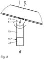
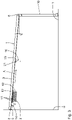
- a support beam 16 runs transversely thereto between the two guide rails 3, 4 parallel to the end rails 5, 6, which with its two ends 17, 18, via pivot bearing arms 19, 20 running essentially vertically, is positioned opposite the supporting frame 1 positioned suspended below.
- the pivot bearing arms 19, 20 are articulated with their upper end in a pivot joint 21, 22 on the underside of the guide rails 3, 4 pivotable about a pivot axis S. This allows the pivot bearing arms 19, 20, as shown in the Figures 2 to 4 is clear, regardless of the angle of inclination N of the support frame 1 are always set exactly vertically.
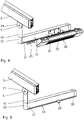
- the support beam 16 is designed as a hollow profile with high load capacity. He can one or more electrical supply lines 23 for based on Figures 7 to 9 include the accessory components described.
- the hollow profile is an extruded chamber profile that is essentially rectangular in cross-section, multifunction grooves 25 that are open to the outside being provided by corresponding intermediate walls 24 in the lower edge regions in or counter to the drop direction. It can be used in cross-section adapted, strand-like LED light rails 27 - see 7 - Or by appropriate brackets (not shown) spotlights 29 - see 9 - to be assembled. Larger volume and heavier heat radiators 28 - see 8 - Can also be screwed directly to the side walls 31 of the support beam 16 via retaining plates 30.
- the pivot bearing arms 19, 20 are also designed as a hollow profile with a flat-rectangular cross section, through which the supply lines 23 emerge from the respective guide rails from above 3, 4 can be introduced and continued at the lower end to the cavity of the support beam 16.
- the transition area between the pivot bearing arms 19, 20 and the support beam 16 is closed by a lateral cover cap 32, as a result of which the hollow profile interiors 37 and the supply lines 23 are covered.
- an L-shaped mounting bracket 33 is provided between these two components, which is screwed with its vertical leg 34 to the respective pivot bearing arm 19, 20 and with its horizontal leg 35 in corresponding grooves 36 is inserted in the hollow profile interior 37.
Abstract
Eine Markise, insbesondere Wintergarten- oder Wetterschutzmarkise, umfasst einen Markisenbehang (2), einen Tragrahmen (1) mit in Ausfallrichtung (A) des Markisenbehangs (2) verlaufenden, seitlichen Führungsschienen (3, 4) für den Markisenbehang (2) und quer dazu verlaufenden Endschienen (5, 6) zur stationären Halterung der Markise an einem Gebäude (G) und/oder auf Stützen (10, 11), sowie mindestens einen Stützträger (16), der quer zur Ausfallrichtung (A) zwischen den beiden Führungsschienen (3, 4) unterhalb des Markisenbehangs (2) angeordnet ist, wobei der mindestens eine Stützträger (16) an seinen beiden Enden (17, 18) jeweils über einen vertikal verlaufenden Schwenklagerarm (19, 20) gegenüber dem Tragrahmen (1) nach unten abgehängt und um eine horizontale, quer zur Ausfallrichtung (A) verlaufende Schwenkachse (S) schwenkbar an den Führungsschienen (3, 4) angelenkt ist.An awning, in particular a conservatory or weather protection awning, comprises an awning curtain (2), a support frame (1) with lateral guide rails (3, 4) for the awning curtain (2) running in the projection direction (A) of the awning curtain (2) and transversely thereto running end rails (5, 6) for the stationary mounting of the awning on a building (G) and/or on supports (10, 11), as well as at least one support beam (16) which runs transversely to the projection direction (A) between the two guide rails (3 , 4) is arranged below the awning curtain (2), the at least one support beam (16) being suspended downwards at both of its ends (17, 18) via a vertically running pivot bearing arm (19, 20) in relation to the support frame (1) and is articulated on the guide rails (3, 4) so as to be pivotable about a horizontal pivot axis (S) running transversely to the direction of projection (A).
Description
Die Erfindung betrifft eine Markise und insbesondere Wintergarten- oder Wetterschutzmarkise mit den im Oberbegriff des Schutzanspruches 1 angegebenen Merkmalen.The invention relates to an awning and in particular a conservatory or weather protection awning with the features specified in the preamble of claim 1.
Eine derartige Markise ist beispielsweise aus der
Dieser Stützträger dient zur Stabilisierung der Markise und zur Halterung verschiedener Zubehörkomponenten, wie beispielsweise Wärmestrahler, Leuchtspots, Lichtstrahlen oder Lautsprecher. Nachteilig bei der bekannten Konstruktion ist die enge Anbindung des Stützträgers an die Unterseite der Führungsschienen, sodass eine räumliche Nähe zwischen dem Stützträger und dem darüber vorbeilaufenden Markisenbehang besteht. Damit besteht insbesondere bei einer baldachinartigen Ausbildung des Markisenbehangs mit nach unten durchhängenden Faltstreifen die Gefahr, dass das Markisentuch auf dem Stützträger schleift und damit verschleißanfällig wird. Darüber hinaus ist der bekannte Stützträger starr an die Führungsschienen angebunden, sodass bei geneigten Führungsschienen der Stützträger verkippt angeordnet ist.This support bracket is used to stabilize the awning and to hold various accessory components, such as radiant heaters, spotlights, light beams or loudspeakers. A disadvantage of the known construction is the close connection of the support beam to the underside of the guide rails, so that there is spatial proximity between the support beam and the awning curtain running past it. This means that there is a risk, particularly in the case of a canopy-like design of the awning curtain with folded strips sagging downwards, that the awning fabric will drag on the support beam and thus become susceptible to wear. In addition, the known support beam is rigidly connected to the guide rails, so that the support beam is tilted when the guide rails are inclined.
Ausgehend von den geschilderten Problemen liegt der Erfindung die Aufgabe zugrunde, eine Markise der Gattung gemäß den Art so zu verbessern, dass die Anordnung und Positionierbarkeit des Stützträgers flexibler werden und ein größerer Abstand zum Markisenbehang gewährleistet wird.Proceeding from the problems described, the invention is based on the object of improving an awning of the type according to the type in such a way that the arrangement and positionability of the support beam become more flexible and a greater distance from the awning curtain is ensured.
Diese Aufgabe wird durch die im Kennzeichnungsteil des Anspruchs 1 angegebenen Merkmale gelöst, wonach der Stützträger an seinen beiden Enden jeweils über einen vertikal verlaufenden Schwenklagerarm gegenüber dem Tragrahmen nach unten abgehängt und um eine horizontale, quer zur Ausfallrichtung verlaufende Schwenkachse schwenkbar an den Führungsschienen angelenkt ist.This object is achieved by the features specified in the characterizing part of claim 1, according to which the support beam is suspended at both ends via a vertically running pivot bearing arm relative to the support frame and is pivoted to the guide rails so that it can pivot about a horizontal pivot axis running transversely to the direction of failure.
Durch die nach unten abgehängte Konfiguration der Stützträger-Lagerung ergibt sich der gewünschte ausreichende Abstand zwischen dem Stützträger und dem Markisenbehang, sodass eine gegenseitige Berührung dieser Komponenten nicht mehr zu befürchten steht. Durch die schwenkbare Lagerung der Schwenklagerarme der Stützträger können diese Arme unabhängig von der Neigung der Führungsschienen immer sauber vertikal eingestellt werden, sodass der eigentliche Stützträger sowohl um seine Längsals auch Querachse horizontal angeordnet werden kann. An der Unterseite des Stützträgers angebrachte, nach unten abstrahlende Wärmestrahler erfassen damit exakt den vertikal unter ihnen liegenden Bereich.The configuration of the support beam bearing suspended downwards results in the desired sufficient distance between the support beam and the awning curtain, so that there is no longer any fear of these components touching each other. Due to the pivoting bearing of the pivot bearing arms of the support beams, these arms can always be correctly adjusted vertically, regardless of the inclination of the guide rails, so that the actual support beam can be arranged horizontally both around its longitudinal and transverse axis. Heat radiators attached to the underside of the support beam and radiating downwards precisely cover the area vertically below them.
In den abhängigen Ansprüchen sind bevorzugte Weiterbildungen der Erfindung angegeben. So kann der Stützträger in an sich bekannter Weise für daran anzubringende Zubehörkomponenten, wie Wärmestrahler, Leuchtspots, Lichtschienen, Lautsprecher oder dergleichen dienen. Zu diesem Zweck ist es dann vorteilhaft, wenn der Stützträger als Hohlprofil mit hoher Tragfähigkeit ausgelegt ist, sodass er zum einen zur verborgenen Aufnahme und Weiterführung von elektrischen Versorgungsleitungen für diese Zubehörkomponenten und zum anderen für eine stabile, durchbiegungsfreie Lagerung dieser Zubehörkomponenten gerade auch bei vielzähligen und/oder schwergewichtigen Komponenten dient.Preferred developments of the invention are specified in the dependent claims. Thus, the support beam can be used in a manner known per se for accessory components to be attached to it, such as heat radiators, spotlights, light rails, loudspeakers or the like. For this purpose, it is advantageous if the support beam as a hollow profile with high Carrying capacity is designed so that it is used on the one hand for concealed recording and continuation of electrical supply lines for these accessory components and on the other hand for stable, deflection-free storage of these accessory components, especially with numerous and / or heavy components.
Zur positionsflexiblen Halterung solcher Zubehörkomponenten ist der Stützträger gemäß einer bevorzugten Weiterbildung auf seiner Außenseite mit mindestens einer Multifunktionsnut versehen. Damit können unterschiedliche Zubehörkomponenten an unterschiedlichen Positionen auf einfache Weise am Sturzträger befestigt werden.For position-flexible mounting of such accessory components, according to a preferred development, the support carrier is provided with at least one multifunctional groove on its outside. This allows different accessory components to be attached to the lintel carrier in different positions in a simple manner.
Eine vorteilhafte Ausführungsform der Erfindung sieht ferner eine zwischen den benachbarten Enden des Stützträgers und der vorzugsweise ebenfalls als Hohlprofile zur Aufnahme von elektrischen Versorgungsleitungen ausgebildeten Schwenklagerarme angeordnete Abdeckkappe vor, mit deren Hilfe die in den Hohlprofil-Innenräumen verlaufenden Versorgungsleitungen zwischen den Schwenklagerarmen und dem Stützträger verdeckt geführt werden können. Dies kommt einem aufgeräumten Erscheinungsbild der erfindungsgemäßen Markise zugute.An advantageous embodiment of the invention also provides a cover cap arranged between the adjacent ends of the support beam and the pivot bearing arms, which are preferably also designed as hollow profiles for accommodating electrical supply lines, with the help of which the supply lines running in the hollow profile interior spaces between the pivot bearing arms and the support beam are concealed can become. This benefits a tidy appearance of the awning according to the invention.
In einer weiteren bevorzugten Ausbildung der Erfindung ist die Schwenkachse für die Schwenklagerarme jeweils durch ein unten an den Markisen-Führungsschienen angebrachtes Drehgelenk gebildet, was eine konstruktiv einfache, robuste Auslegung der Schwenkachse mit sich bringt.In a further preferred embodiment of the invention, the pivot axis for the pivot bearing arms is formed by a swivel joint attached to the bottom of the awning guide rails, which entails a structurally simple, robust design of the pivot axis.
Weitere vorteilhafte Ausführungsformen der Erfindung beziehen sich auf die Wahl des Markisenbehanges. Dieser kann beispielsweise ein im wesentlichen eben gespanntes Markisentuch sein, das - wie aus der eingangs genannten
Alternativ dazu kann der Behang auch ein baldachinartiges Markisentuch sein, dass in Streifenzonen eingeteilt und über ein Ausfallprofil sowie ebenfalls in den Führungsschienen verschiebbar gelagerte, die Streifenzonen bildende Tuchschienen geführt ist.As an alternative to this, the curtain can also be a canopy-like awning fabric that is divided into strip zones and guided via a drop profile and fabric rails that are also slidably mounted in the guide rails and form the strip zones.
Weitere Merkmale, Einzelheiten und Vorteile der Erfindung ergeben sich aus der nachfolgenden Beschreibung eines Ausführungsbeispiels anhand der beigefügten Zeichnungen. Es zeigen:
- Fig. 1
- eine perspektivische Ansicht einer Markise,
- Fig. 2
- eine Seitenansicht der Einzelheit II nach
Fig. 1 , - Fig. 3 und 4
- Seitenansichten der Markise mit unterschiedlichen Neigungen,
- Fig. 5
- einen Vertikalschnitt entlang der Schnittlinie III - III nach
Fig. 2 , - Fig. 6
- einen Querschnitt durch einen Stützträger, sowie
- Fig. 7 bis 9
- perspektivische Teilansichten der Markise gemäß
Fig. 1 mit Stützträgern und unterschiedlichen daran befes-tigten Zubehörkomponenten.
- 1
- a perspective view of an awning,
- 2
- according to a side view of detail II
1 , - Figures 3 and 4
- side views of the awning with different inclinations,
- figure 5
- a vertical section along the section line III - III
2 , - 6
- a cross section through a support beam, and
- Figures 7 to 9
- Perspective partial views of the awning according to
1 with support beams and various accessories attached to them.
Anhand von
Mit der einen Endschiene 5 ist die Markise über entsprechende Konsolen 8 an einer Gebäudewand G montiert, die gegenüberliegende Endschiene 6 ruht auf Stützen 10, 11, die beispielsweise auf einer zu überdachenden Terrasse T stehen.With one
Bei dem Markisenbehang 1 handelt es sich im gezeigten Ausführungsbeispiel um ein Markisentuch 12, das mit seinem in Ausfallrichtung A weisenden Ende in einem quer zur Ausfallrichtung A verlaufenden, in dieser Richtung verschiebbar angetrieben in den Führungsschienen 3, 4 geführten Ausfallprofil 13 befestigt ist. Das Markisentuch 12 ist ferner baldachinartig in einzelne Streifenzonen 14 eingeteilt und mit dem Rand jeder seiner Zonen 14 an einer Tuchhalteschiene 15 befestigt. Letztere sind mit ihren Enden frei in den Führungsschienen 3, 4 in Ausfallrichtung A verschiebbar geführt und verschieben sich unter dem Einfluss der Schwerkraft und der Zugwirkung des Ausfallprofils 13 aus der in
Etwa mittig bezogen auf die Ausfallrichtung A verläuft quer dazu zwischen den beiden Führungsschienen 3, 4 parallel zu den Endschienen 5, 6 ein Stützträger 16, der mit seinen beiden Enden 17, 18 über im wesentlichen vertikal verlaufende Schwenklagerarme 19, 20 gegenüber dem Tragrahmen 1 nach unten abgehängt positioniert ist. Die Schwenklagerarme 19, 20 sind mit ihrem oberen Ende jeweils in einem Drehgelenk 21, 22 an der Unterseite der Führungsschienen 3, 4 um eine Schwenkachse S schwenkbar angelenkt. Dadurch können die Schwenklagerarme 19, 20, wie aus den
Wie aus den
Wie aus
Zur stabilen Verbindung zwischen den Schwenklagerarmen 19, 20 und dem Stützträger 16 ist ein L-förmiger Befestigungswinkel 33 zwischen diesen beiden Bauteilen vorgesehen, der mit seinem vertikalen Schenkel 34 mit dem jeweiligen Schwenklagerarm 19, 20 verschraubt und mit seinem horizontalen Schenkel 35 in entsprechende Nuten 36 im Hohlprofil-Innenraum 37 eingesteckt ist.For a stable connection between the
Der Vollständigkeit halber wird im Zusammenhang mit
Claims (8)
Applications Claiming Priority (1)
| Application Number | Priority Date | Filing Date | Title |
|---|---|---|---|
| DE202020105900.9U DE202020105900U1 (en) | 2020-10-15 | 2020-10-15 | Awning, in particular a conservatory or weather protection awning, with a support beam |
Publications (2)
| Publication Number | Publication Date |
|---|---|
| EP3985201A1 true EP3985201A1 (en) | 2022-04-20 |
| EP3985201B1 EP3985201B1 (en) | 2023-06-07 |
Family
ID=78085780
Family Applications (1)
| Application Number | Title | Priority Date | Filing Date |
|---|---|---|---|
| EP21198471.1A Active EP3985201B1 (en) | 2020-10-15 | 2021-09-23 | Awning, in particular a winter garden or a weather guard with a support |
Country Status (5)
| Country | Link |
|---|---|
| EP (1) | EP3985201B1 (en) |
| DE (1) | DE202020105900U1 (en) |
| DK (1) | DK3985201T3 (en) |
| ES (1) | ES2949233T3 (en) |
| PL (1) | PL3985201T3 (en) |
Citations (2)
| Publication number | Priority date | Publication date | Assignee | Title |
|---|---|---|---|---|
| KR101653114B1 (en) * | 2015-10-22 | 2016-08-31 | 정금필 | Roller apparatus for sky awning and, sky awning comprising the same |
| DE202016106962U1 (en) | 2015-12-18 | 2016-12-30 | Schmitz-Werke Gmbh + Co. Kg | Awning, in particular conservatory awning, with lighting |
-
2020
- 2020-10-15 DE DE202020105900.9U patent/DE202020105900U1/en active Active
-
2021
- 2021-09-23 EP EP21198471.1A patent/EP3985201B1/en active Active
- 2021-09-23 PL PL21198471.1T patent/PL3985201T3/en unknown
- 2021-09-23 ES ES21198471T patent/ES2949233T3/en active Active
- 2021-09-23 DK DK21198471.1T patent/DK3985201T3/en active
Patent Citations (2)
| Publication number | Priority date | Publication date | Assignee | Title |
|---|---|---|---|---|
| KR101653114B1 (en) * | 2015-10-22 | 2016-08-31 | 정금필 | Roller apparatus for sky awning and, sky awning comprising the same |
| DE202016106962U1 (en) | 2015-12-18 | 2016-12-30 | Schmitz-Werke Gmbh + Co. Kg | Awning, in particular conservatory awning, with lighting |
Also Published As
| Publication number | Publication date |
|---|---|
| DE202020105900U1 (en) | 2022-01-26 |
| ES2949233T3 (en) | 2023-09-26 |
| EP3985201B1 (en) | 2023-06-07 |
| DK3985201T3 (en) | 2023-08-28 |
| PL3985201T3 (en) | 2023-10-09 |
Similar Documents
| Publication | Publication Date | Title |
|---|---|---|
| DE102012000580B4 (en) | sun protection | |
| DE3408379C2 (en) | Retractable tent roof, especially awning, awning for motorhomes and the like. | |
| EP0119550B1 (en) | Collapsible tent roof, in particular an awning, tent canopy for dormobiles and the like | |
| EP3985201B1 (en) | Awning, in particular a winter garden or a weather guard with a support | |
| DE3001919C2 (en) | awning | |
| EP0631025B1 (en) | Sunshade with support bar | |
| EP2826945A2 (en) | Vertical shading | |
| DE4105520C2 (en) | awning | |
| DE19524420C2 (en) | Awning with retractable valance | |
| DE4015995C2 (en) | Sun protection | |
| EP3054063A1 (en) | Awning with lowerable guide rails | |
| EP3992389B1 (en) | Covering with shading elements | |
| EP1724411B1 (en) | Awning | |
| EP0617191B1 (en) | Guiding arrangement for greenhouse awnings or similar | |
| DE102020213049B3 (en) | Mounting bracket for mounting an awning on a building and awning equipped therewith | |
| DE2146286C2 (en) | Weather and privacy shield | |
| DE102011119726A1 (en) | Cassette awning with concealed mounting brackets | |
| EP2189314B1 (en) | Device with at least one tensionable area element | |
| WO2005088026A1 (en) | Extendable shading device | |
| DE102017210535B4 (en) | Weather protection awning with at least two frame fields | |
| EP1104829B1 (en) | Boxed awning | |
| DE19503263A1 (en) | Sun awning with wind-up shaft | |
| EP1698737A2 (en) | Roof construction | |
| DE202005010974U1 (en) | Extensible sunshade for use in vehicle e.g. mobile home, ship, or building e.g. greenhouse, winter garden, has pair of extension mechanisms, each having connected pairs of asymmetrical criss crossing links | |
| DE10014144A1 (en) | Sleeve awning |
Legal Events
| Date | Code | Title | Description |
|---|---|---|---|
| PUAI | Public reference made under article 153(3) epc to a published international application that has entered the european phase |
Free format text: ORIGINAL CODE: 0009012 |
|
| STAA | Information on the status of an ep patent application or granted ep patent |
Free format text: STATUS: THE APPLICATION HAS BEEN PUBLISHED |
|
| AK | Designated contracting states |
Kind code of ref document: A1 Designated state(s): AL AT BE BG CH CY CZ DE DK EE ES FI FR GB GR HR HU IE IS IT LI LT LU LV MC MK MT NL NO PL PT RO RS SE SI SK SM TR |
|
| STAA | Information on the status of an ep patent application or granted ep patent |
Free format text: STATUS: REQUEST FOR EXAMINATION WAS MADE |
|
| 17P | Request for examination filed |
Effective date: 20220922 |
|
| RBV | Designated contracting states (corrected) |
Designated state(s): AL AT BE BG CH CY CZ DE DK EE ES FI FR GB GR HR HU IE IS IT LI LT LU LV MC MK MT NL NO PL PT RO RS SE SI SK SM TR |
|
| GRAP | Despatch of communication of intention to grant a patent |
Free format text: ORIGINAL CODE: EPIDOSNIGR1 |
|
| STAA | Information on the status of an ep patent application or granted ep patent |
Free format text: STATUS: GRANT OF PATENT IS INTENDED |
|
| INTG | Intention to grant announced |
Effective date: 20230131 |
|
| GRAS | Grant fee paid |
Free format text: ORIGINAL CODE: EPIDOSNIGR3 |
|
| GRAA | (expected) grant |
Free format text: ORIGINAL CODE: 0009210 |
|
| STAA | Information on the status of an ep patent application or granted ep patent |
Free format text: STATUS: THE PATENT HAS BEEN GRANTED |
|
| AK | Designated contracting states |
Kind code of ref document: B1 Designated state(s): AL AT BE BG CH CY CZ DE DK EE ES FI FR GB GR HR HU IE IS IT LI LT LU LV MC MK MT NL NO PL PT RO RS SE SI SK SM TR |
|
| REG | Reference to a national code |
Ref country code: GB Ref legal event code: FG4D Free format text: NOT ENGLISH |
|
| REG | Reference to a national code |
Ref country code: CH Ref legal event code: EP Ref country code: AT Ref legal event code: REF Ref document number: 1575471 Country of ref document: AT Kind code of ref document: T Effective date: 20230615 Ref country code: DE Ref legal event code: R096 Ref document number: 502021000808 Country of ref document: DE |
|
| P01 | Opt-out of the competence of the unified patent court (upc) registered |
Effective date: 20230516 |
|
| REG | Reference to a national code |
Ref country code: DK Ref legal event code: T3 Effective date: 20230823 |
|
| REG | Reference to a national code |
Ref country code: SE Ref legal event code: TRGR |
|
| REG | Reference to a national code |
Ref country code: NL Ref legal event code: FP |
|
| REG | Reference to a national code |
Ref country code: NO Ref legal event code: T2 Effective date: 20230607 |
|
| REG | Reference to a national code |
Ref country code: LT Ref legal event code: MG9D |
|
| REG | Reference to a national code |
Ref country code: ES Ref legal event code: FG2A Ref document number: 2949233 Country of ref document: ES Kind code of ref document: T3 Effective date: 20230926 |
|
| PGFP | Annual fee paid to national office [announced via postgrant information from national office to epo] |
Ref country code: NO Payment date: 20230919 Year of fee payment: 3 Ref country code: LU Payment date: 20230918 Year of fee payment: 3 |
|
| PG25 | Lapsed in a contracting state [announced via postgrant information from national office to epo] |
Ref country code: RS Free format text: LAPSE BECAUSE OF FAILURE TO SUBMIT A TRANSLATION OF THE DESCRIPTION OR TO PAY THE FEE WITHIN THE PRESCRIBED TIME-LIMIT Effective date: 20230607 Ref country code: LV Free format text: LAPSE BECAUSE OF FAILURE TO SUBMIT A TRANSLATION OF THE DESCRIPTION OR TO PAY THE FEE WITHIN THE PRESCRIBED TIME-LIMIT Effective date: 20230607 Ref country code: LT Free format text: LAPSE BECAUSE OF FAILURE TO SUBMIT A TRANSLATION OF THE DESCRIPTION OR TO PAY THE FEE WITHIN THE PRESCRIBED TIME-LIMIT Effective date: 20230607 Ref country code: HR Free format text: LAPSE BECAUSE OF FAILURE TO SUBMIT A TRANSLATION OF THE DESCRIPTION OR TO PAY THE FEE WITHIN THE PRESCRIBED TIME-LIMIT Effective date: 20230607 Ref country code: GR Free format text: LAPSE BECAUSE OF FAILURE TO SUBMIT A TRANSLATION OF THE DESCRIPTION OR TO PAY THE FEE WITHIN THE PRESCRIBED TIME-LIMIT Effective date: 20230908 |
|
| PGFP | Annual fee paid to national office [announced via postgrant information from national office to epo] |
Ref country code: SE Payment date: 20230921 Year of fee payment: 3 Ref country code: PL Payment date: 20230821 Year of fee payment: 3 Ref country code: FR Payment date: 20230918 Year of fee payment: 3 Ref country code: DK Payment date: 20230921 Year of fee payment: 3 Ref country code: BE Payment date: 20230918 Year of fee payment: 3 |
|
| PG25 | Lapsed in a contracting state [announced via postgrant information from national office to epo] |
Ref country code: FI Free format text: LAPSE BECAUSE OF FAILURE TO SUBMIT A TRANSLATION OF THE DESCRIPTION OR TO PAY THE FEE WITHIN THE PRESCRIBED TIME-LIMIT Effective date: 20230607 |
|
| PG25 | Lapsed in a contracting state [announced via postgrant information from national office to epo] |
Ref country code: SK Free format text: LAPSE BECAUSE OF FAILURE TO SUBMIT A TRANSLATION OF THE DESCRIPTION OR TO PAY THE FEE WITHIN THE PRESCRIBED TIME-LIMIT Effective date: 20230607 |
|
| PGFP | Annual fee paid to national office [announced via postgrant information from national office to epo] |
Ref country code: ES Payment date: 20231019 Year of fee payment: 3 |
|
| PG25 | Lapsed in a contracting state [announced via postgrant information from national office to epo] |
Ref country code: IS Free format text: LAPSE BECAUSE OF FAILURE TO SUBMIT A TRANSLATION OF THE DESCRIPTION OR TO PAY THE FEE WITHIN THE PRESCRIBED TIME-LIMIT Effective date: 20231007 |
|
| PG25 | Lapsed in a contracting state [announced via postgrant information from national office to epo] |
Ref country code: SM Free format text: LAPSE BECAUSE OF FAILURE TO SUBMIT A TRANSLATION OF THE DESCRIPTION OR TO PAY THE FEE WITHIN THE PRESCRIBED TIME-LIMIT Effective date: 20230607 Ref country code: SK Free format text: LAPSE BECAUSE OF FAILURE TO SUBMIT A TRANSLATION OF THE DESCRIPTION OR TO PAY THE FEE WITHIN THE PRESCRIBED TIME-LIMIT Effective date: 20230607 Ref country code: RO Free format text: LAPSE BECAUSE OF FAILURE TO SUBMIT A TRANSLATION OF THE DESCRIPTION OR TO PAY THE FEE WITHIN THE PRESCRIBED TIME-LIMIT Effective date: 20230607 Ref country code: PT Free format text: LAPSE BECAUSE OF FAILURE TO SUBMIT A TRANSLATION OF THE DESCRIPTION OR TO PAY THE FEE WITHIN THE PRESCRIBED TIME-LIMIT Effective date: 20231009 Ref country code: IS Free format text: LAPSE BECAUSE OF FAILURE TO SUBMIT A TRANSLATION OF THE DESCRIPTION OR TO PAY THE FEE WITHIN THE PRESCRIBED TIME-LIMIT Effective date: 20231007 Ref country code: EE Free format text: LAPSE BECAUSE OF FAILURE TO SUBMIT A TRANSLATION OF THE DESCRIPTION OR TO PAY THE FEE WITHIN THE PRESCRIBED TIME-LIMIT Effective date: 20230607 Ref country code: CZ Free format text: LAPSE BECAUSE OF FAILURE TO SUBMIT A TRANSLATION OF THE DESCRIPTION OR TO PAY THE FEE WITHIN THE PRESCRIBED TIME-LIMIT Effective date: 20230607 |
|
| PGFP | Annual fee paid to national office [announced via postgrant information from national office to epo] |
Ref country code: IT Payment date: 20230930 Year of fee payment: 3 Ref country code: DE Payment date: 20231124 Year of fee payment: 3 |
|
| REG | Reference to a national code |
Ref country code: DE Ref legal event code: R097 Ref document number: 502021000808 Country of ref document: DE |
|
| PLBE | No opposition filed within time limit |
Free format text: ORIGINAL CODE: 0009261 |
|
| STAA | Information on the status of an ep patent application or granted ep patent |
Free format text: STATUS: NO OPPOSITION FILED WITHIN TIME LIMIT |