EP3984513B1 - Rehabilitationsübungsgerät für obere und untere gliedmassen - Google Patents
Rehabilitationsübungsgerät für obere und untere gliedmassen Download PDFInfo
- Publication number
- EP3984513B1 EP3984513B1 EP20888679.6A EP20888679A EP3984513B1 EP 3984513 B1 EP3984513 B1 EP 3984513B1 EP 20888679 A EP20888679 A EP 20888679A EP 3984513 B1 EP3984513 B1 EP 3984513B1
- Authority
- EP
- European Patent Office
- Prior art keywords
- fixing plate
- restraining
- support
- plate
- shaft
- Prior art date
- Legal status (The legal status is an assumption and is not a legal conclusion. Google has not performed a legal analysis and makes no representation as to the accuracy of the status listed.)
- Active
Links
Images


Classifications
-
- A—HUMAN NECESSITIES
- A61—MEDICAL OR VETERINARY SCIENCE; HYGIENE
- A61H—PHYSICAL THERAPY APPARATUS, e.g. DEVICES FOR LOCATING OR STIMULATING REFLEX POINTS IN THE BODY; ARTIFICIAL RESPIRATION; MASSAGE; BATHING DEVICES FOR SPECIAL THERAPEUTIC OR HYGIENIC PURPOSES OR SPECIFIC PARTS OF THE BODY
- A61H1/00—Apparatus for passive exercising; Vibrating apparatus; Chiropractic devices, e.g. body impacting devices, external devices for briefly extending or aligning unbroken bones
- A61H1/02—Stretching or bending or torsioning apparatus for exercising
- A61H1/0237—Stretching or bending or torsioning apparatus for exercising for the lower limbs
- A61H1/024—Knee
-
- A—HUMAN NECESSITIES
- A61—MEDICAL OR VETERINARY SCIENCE; HYGIENE
- A61H—PHYSICAL THERAPY APPARATUS, e.g. DEVICES FOR LOCATING OR STIMULATING REFLEX POINTS IN THE BODY; ARTIFICIAL RESPIRATION; MASSAGE; BATHING DEVICES FOR SPECIAL THERAPEUTIC OR HYGIENIC PURPOSES OR SPECIFIC PARTS OF THE BODY
- A61H1/00—Apparatus for passive exercising; Vibrating apparatus; Chiropractic devices, e.g. body impacting devices, external devices for briefly extending or aligning unbroken bones
- A61H1/02—Stretching or bending or torsioning apparatus for exercising
- A61H1/0237—Stretching or bending or torsioning apparatus for exercising for the lower limbs
- A61H1/0266—Foot
-
- A—HUMAN NECESSITIES
- A61—MEDICAL OR VETERINARY SCIENCE; HYGIENE
- A61H—PHYSICAL THERAPY APPARATUS, e.g. DEVICES FOR LOCATING OR STIMULATING REFLEX POINTS IN THE BODY; ARTIFICIAL RESPIRATION; MASSAGE; BATHING DEVICES FOR SPECIAL THERAPEUTIC OR HYGIENIC PURPOSES OR SPECIFIC PARTS OF THE BODY
- A61H1/00—Apparatus for passive exercising; Vibrating apparatus; Chiropractic devices, e.g. body impacting devices, external devices for briefly extending or aligning unbroken bones
- A61H1/02—Stretching or bending or torsioning apparatus for exercising
- A61H1/0274—Stretching or bending or torsioning apparatus for exercising for the upper limbs
- A61H1/0277—Elbow
-
- A—HUMAN NECESSITIES
- A61—MEDICAL OR VETERINARY SCIENCE; HYGIENE
- A61H—PHYSICAL THERAPY APPARATUS, e.g. DEVICES FOR LOCATING OR STIMULATING REFLEX POINTS IN THE BODY; ARTIFICIAL RESPIRATION; MASSAGE; BATHING DEVICES FOR SPECIAL THERAPEUTIC OR HYGIENIC PURPOSES OR SPECIFIC PARTS OF THE BODY
- A61H1/00—Apparatus for passive exercising; Vibrating apparatus; Chiropractic devices, e.g. body impacting devices, external devices for briefly extending or aligning unbroken bones
- A61H1/02—Stretching or bending or torsioning apparatus for exercising
- A61H1/0274—Stretching or bending or torsioning apparatus for exercising for the upper limbs
- A61H1/0285—Hand
-
- A—HUMAN NECESSITIES
- A61—MEDICAL OR VETERINARY SCIENCE; HYGIENE
- A61H—PHYSICAL THERAPY APPARATUS, e.g. DEVICES FOR LOCATING OR STIMULATING REFLEX POINTS IN THE BODY; ARTIFICIAL RESPIRATION; MASSAGE; BATHING DEVICES FOR SPECIAL THERAPEUTIC OR HYGIENIC PURPOSES OR SPECIFIC PARTS OF THE BODY
- A61H2201/00—Characteristics of apparatus not provided for in the preceding codes
- A61H2201/01—Constructive details
- A61H2201/0157—Constructive details portable
-
- A—HUMAN NECESSITIES
- A61—MEDICAL OR VETERINARY SCIENCE; HYGIENE
- A61H—PHYSICAL THERAPY APPARATUS, e.g. DEVICES FOR LOCATING OR STIMULATING REFLEX POINTS IN THE BODY; ARTIFICIAL RESPIRATION; MASSAGE; BATHING DEVICES FOR SPECIAL THERAPEUTIC OR HYGIENIC PURPOSES OR SPECIFIC PARTS OF THE BODY
- A61H2201/00—Characteristics of apparatus not provided for in the preceding codes
- A61H2201/01—Constructive details
- A61H2201/0161—Size reducing arrangements when not in use, for stowing or transport
-
- A—HUMAN NECESSITIES
- A61—MEDICAL OR VETERINARY SCIENCE; HYGIENE
- A61H—PHYSICAL THERAPY APPARATUS, e.g. DEVICES FOR LOCATING OR STIMULATING REFLEX POINTS IN THE BODY; ARTIFICIAL RESPIRATION; MASSAGE; BATHING DEVICES FOR SPECIAL THERAPEUTIC OR HYGIENIC PURPOSES OR SPECIFIC PARTS OF THE BODY
- A61H2201/00—Characteristics of apparatus not provided for in the preceding codes
- A61H2201/01—Constructive details
- A61H2201/0192—Specific means for adjusting dimensions
-
- A—HUMAN NECESSITIES
- A61—MEDICAL OR VETERINARY SCIENCE; HYGIENE
- A61H—PHYSICAL THERAPY APPARATUS, e.g. DEVICES FOR LOCATING OR STIMULATING REFLEX POINTS IN THE BODY; ARTIFICIAL RESPIRATION; MASSAGE; BATHING DEVICES FOR SPECIAL THERAPEUTIC OR HYGIENIC PURPOSES OR SPECIFIC PARTS OF THE BODY
- A61H2201/00—Characteristics of apparatus not provided for in the preceding codes
- A61H2201/12—Driving means
- A61H2201/1207—Driving means with electric or magnetic drive
- A61H2201/1215—Rotary drive
-
- A—HUMAN NECESSITIES
- A61—MEDICAL OR VETERINARY SCIENCE; HYGIENE
- A61H—PHYSICAL THERAPY APPARATUS, e.g. DEVICES FOR LOCATING OR STIMULATING REFLEX POINTS IN THE BODY; ARTIFICIAL RESPIRATION; MASSAGE; BATHING DEVICES FOR SPECIAL THERAPEUTIC OR HYGIENIC PURPOSES OR SPECIFIC PARTS OF THE BODY
- A61H2201/00—Characteristics of apparatus not provided for in the preceding codes
- A61H2201/14—Special force transmission means, i.e. between the driving means and the interface with the user
- A61H2201/1481—Special movement conversion means
- A61H2201/149—Special movement conversion means rotation-linear or vice versa
-
- A—HUMAN NECESSITIES
- A61—MEDICAL OR VETERINARY SCIENCE; HYGIENE
- A61H—PHYSICAL THERAPY APPARATUS, e.g. DEVICES FOR LOCATING OR STIMULATING REFLEX POINTS IN THE BODY; ARTIFICIAL RESPIRATION; MASSAGE; BATHING DEVICES FOR SPECIAL THERAPEUTIC OR HYGIENIC PURPOSES OR SPECIFIC PARTS OF THE BODY
- A61H2201/00—Characteristics of apparatus not provided for in the preceding codes
- A61H2201/16—Physical interface with patient
- A61H2201/1602—Physical interface with patient kind of interface, e.g. head rest, knee support or lumbar support
- A61H2201/1635—Hand or arm, e.g. handle
- A61H2201/1638—Holding means therefor
-
- A—HUMAN NECESSITIES
- A61—MEDICAL OR VETERINARY SCIENCE; HYGIENE
- A61H—PHYSICAL THERAPY APPARATUS, e.g. DEVICES FOR LOCATING OR STIMULATING REFLEX POINTS IN THE BODY; ARTIFICIAL RESPIRATION; MASSAGE; BATHING DEVICES FOR SPECIAL THERAPEUTIC OR HYGIENIC PURPOSES OR SPECIFIC PARTS OF THE BODY
- A61H2201/00—Characteristics of apparatus not provided for in the preceding codes
- A61H2201/16—Physical interface with patient
- A61H2201/1602—Physical interface with patient kind of interface, e.g. head rest, knee support or lumbar support
- A61H2201/164—Feet or leg, e.g. pedal
- A61H2201/1642—Holding means therefor
-
- A—HUMAN NECESSITIES
- A61—MEDICAL OR VETERINARY SCIENCE; HYGIENE
- A61H—PHYSICAL THERAPY APPARATUS, e.g. DEVICES FOR LOCATING OR STIMULATING REFLEX POINTS IN THE BODY; ARTIFICIAL RESPIRATION; MASSAGE; BATHING DEVICES FOR SPECIAL THERAPEUTIC OR HYGIENIC PURPOSES OR SPECIFIC PARTS OF THE BODY
- A61H2201/00—Characteristics of apparatus not provided for in the preceding codes
- A61H2201/16—Physical interface with patient
- A61H2201/1657—Movement of interface, i.e. force application means
- A61H2201/1676—Pivoting
-
- A—HUMAN NECESSITIES
- A61—MEDICAL OR VETERINARY SCIENCE; HYGIENE
- A61H—PHYSICAL THERAPY APPARATUS, e.g. DEVICES FOR LOCATING OR STIMULATING REFLEX POINTS IN THE BODY; ARTIFICIAL RESPIRATION; MASSAGE; BATHING DEVICES FOR SPECIAL THERAPEUTIC OR HYGIENIC PURPOSES OR SPECIFIC PARTS OF THE BODY
- A61H2201/00—Characteristics of apparatus not provided for in the preceding codes
- A61H2201/50—Control means thereof
- A61H2201/5058—Sensors or detectors
- A61H2201/5064—Position sensors
-
- A—HUMAN NECESSITIES
- A61—MEDICAL OR VETERINARY SCIENCE; HYGIENE
- A61H—PHYSICAL THERAPY APPARATUS, e.g. DEVICES FOR LOCATING OR STIMULATING REFLEX POINTS IN THE BODY; ARTIFICIAL RESPIRATION; MASSAGE; BATHING DEVICES FOR SPECIAL THERAPEUTIC OR HYGIENIC PURPOSES OR SPECIFIC PARTS OF THE BODY
- A61H2201/00—Characteristics of apparatus not provided for in the preceding codes
- A61H2201/50—Control means thereof
- A61H2201/5097—Control means thereof wireless
Definitions
- the present disclosure relates generally to a rehabilitation exercise device for upper and lower limbs. More particularly, the present disclosure relates to a rehabilitation exercise device for upper and lower limbs, capable of enabling a user to perform an upper or lower limb rehabilitation exercise by placing his/her upper or lower limb thereon.
- each joint of a human body has a structure in which neighboring parts of the joint are rotatable with respect to the joint.
- Such a rehabilitation exercise device disclosed in the related art has an unnecessarily complex structure, and thus is problematic in that it is difficult to provide benefits to more users because they need to bear the cost of purchase and installation.
- the rehabilitation exercise device is difficult to move, so most users need to move for exercise to the place where the device is located, which is cumbersome.
- KR 10-1163903 relates to an exoskeleton robot for upper limb rehabilitation of stroke patients.
- US 2015/342817 Al illustrates for example a lower limb rehabilitation training robot is provided, which includes a bedstead support and a rising bedstead arranged on the bedstead support, and further includes a linear motion device, a push rod device, a bionic leg arranged at one end of a surface of the rising bedstead and hinged to the rising bedstead, and a bed board configured to support a patient and arranged at another end of the rising bedstead.
- the linear motion device is arranged between the bedstead support and the rising bedstead, is configured to allow the rising bedstead to slide along the bedstead support, and has one lateral surface connected to the bedstead support and another lateral surface hinged to the rising bedstead.
- WO 2019/116779 Al relates to a walking motion assisting apparatus including an actuator unit which controls operation of a driving body so as to impart to the lower leg an assistive force calculated by applying, to output pattern stored data, a walking motion timing based on a thigh phase angle to be detected; and a terminal device which can wirelessly communicate with a control device of the actuator unit.
- the terminal device can receive input of an assistive force setting, which includes the duration that the assistive force is applied in a walking cycle, and produces, on the basis of the assistive force setting, output pattern setting data which indicates the relationship between the walking motion timing and the magnitude of the assistive force to be imparted to the lower leg.
- KR 2012 0086996 A concerns a mechanism for assisting an upper limb muscle is provided to be freely used by installing a plurality of frames and joint links.
- KR 2018 0090031 A relates to an exoskeleton system for assisting lower limb joints, comprising a first assisting unit supporting the hip joint area of human body to assist the movement of the hip joint area of the human body 5 degrees of freedom, a second assisting unit supporting the knee joint area of the human body to assist the movement of the knee joint area by a first degree of freedom; a third assisting unit supporting the ankle joint area of the human body to assist the movement of the ankle joint area by second degrees of freedom, and a driving unit detachably connected to at least one of the first to third assisting units to provide driving force.
- JP H09 271 496 A concerns a device capable of extremely easily and accurately setting a movement range in a short time and smoothly performing continuous joint passive movement for an appropriate movement amount required for training without giving pains to a patient.
- US 2019/344429 A1 relates to a a back module for an exoskeleton structure, comprising a spinal column segment designed to extend along a spinal column of a user, the spinal column segment comprising a plurality of vertebral elements, stacked on one another, and a flexible connecting element connecting the vertebral elements to one another, the spinal column segment having a stable equilibrium position in which the flexible connecting element holds the vertebral elements supported against one another, and the flexible connecting element being elastic so that, during a movement of the back of the user, the flexible connecting element allows a movement of the vertebral elements with respect to one another, while exerting a return force tending to return the spinal column segment the stable equilibrium position.
- an objective of the present disclosure is to provide a rehabilitation exercise device for upper and lower limbs, the rehabilitation exercise device being capable of: enabling a user to perform a rehabilitation exercise by simply adjusting a mounting angle of his/her upper or lower limb in response to the condition of a rehabilitation patient; being simplified in structure, thereby minimizing the cost of purchase and installation; being convenient to move, thereby enabling the elderly or rehabilitation patients with weak muscles to easily move and place the device on a desk, chair, mattress, etc., and then to easily place their upper limb or lower limb on the device; and enabling the user to perform a rehabilitation exercise of each joint of his/her upper limb or lower limb to resemble normal motion.
- a rehabilitation exercise device for upper and lower limbs, the rehabilitation exercise device including: a first support supporting a user's hand or foot; a second support supporting a user's forearm or calf; a pair of first hinges rotatably connecting the first support and the second support to each other; a third support supporting a user's upper arm or thigh; a pair of second hinges rotatably connecting the second support and the third support to each other; and a distance adjustment part configured to adjust a distance between the first support and the third support by adjusting length of the second support.
- the second support comprises: a first fixing plate connected to the pair of first hinges to be rotatably coupled to the first support; a second fixing plate connected to the pair of second hinges to be rotatably coupled to the third support, and configured to be mutually approached or spaced apart with respect to the first fixing plate by the distance adjustment part; a hinge shaft provided between the first fixing plate and the second fixing plate; a first moving plate provided between the first fixing plate and the hinge shaft, and configured to be reciprocally moved therebetween; and a second moving plate provided between the second fixing plate and the hinge shaft, and configured to be reciprocally moved therebetween.
- the distance adjustment part comprises: a first crank rotatably connected to the first fixing plate and the hinge shaft, and configured to convert a rotary motion of the hinge shaft into a linear motion of the first fixing plate; and a second crank rotatably connected to the second fixing plate and the hinge shaft, and is configured to convert the rotary motion of the hinge shaft into a linear motion of the second fixing plate.
- the first crank comprises: a first adjustment link rotatably coupled to the hinge shaft; and a second adjustment link having a first side rotatably coupled to the first adjustment link, and a second side rotatably coupled to the first fixing plate
- the second crank comprises: a third adjustment link rotatably coupled to the hinge shaft; and a fourth adjustment link having a first side rotatably coupled to the third adjustment link, and a second side rotatably coupled to the second fixing plate.
- first crank further comprises a first connection link rotatably coupled to the first moving plate and the first adjustment link; and the second crank further comprises a second connection link rotatably coupled to the second moving plate and the third adjustment link.
- the rehabilitation exercise device further comprises a connection bar connecting the first fixing plate and the second fixing plate to each other.
- any one of the first fixing plate and the second fixing plate is fixed to the connection bar, and a remaining one of the first fixing plate and the second fixing plate is coupled to the connection bar to be movable therealong.
- the rehabilitation exercise device further comprises a length stopper provided on the connection bar, and configured to limit relative movement of the first fixing plate and the second fixing plate.
- the length stopper comprises: a restraining lever rotatably provided on any one of the first fixing plate and the second fixing plate coupled to be movable along the connection bar; and a pressurizing member provided on a rotational trajectory of the restraining lever, and configured to pressurize or release the connection bar by being approached to or spaced apart from the connection bar in response to rotation of the restraining lever.
- the restraining lever comprises: a pusher provided at a first end thereof, and configured to pressurize or release the pressurizing member; and a knob provided at a second end thereof, and configured to rotate the pusher to allow the pusher to pressurize or release the pressurizing member.
- the rehabilitation exercise device further comprises a rotation stopper provided on the hinge shaft, and configured to limit relative movement of the first fixing plate and the second fixing plate.
- the rotation stopper comprises: a restraining dial; a shaft body forming the hinge shaft; a shaft column protruding upward from the shaft body and to which the restraining dial is coupled so as to be rotatable and liftable; and a shaft plate configured to be rotated around the shaft body, and connected to the first adjustment link and the third adjustment link.
- a plurality of restraining holes are formed in the shaft body at a predetermined interval along a circumferential direction of the shaft column;
- the restraining dial comprises a restraining pin protruding from an end thereof oriented toward the shaft body and configured to be inserted into or released from any one selected from among the plurality of restraining holes, and a catching recess depressed in a region of the end of the restraining dial oriented toward the shaft body, at a position spaced apart from the restraining pin;
- the shaft plate comprises a catching protrusion configured to connect the restraining dial to the shaft plate by being caught by the catching recess of the restraining dial.
- the catching protrusion is caught by the catching recess to prevent the restraining dial from being rotated around the shaft column; and when the restraining pin is released from the restraining hole, the catching protrusion is maintained caught by the catching recess, allowing the restraining dial to be rotatable forward and backward around the shaft column, so that the first fixing plate and the second fixing plate are mutually approached or spaced apart with respect to the shaft body.
- the rehabilitation exercise device further comprises an elastic member provided between the shaft column and the restraining dial, and configured to generate an elastic force acting on the restraining dial so that the restraining pin is inserted into the selected restraining hole.
- the rehabilitation exercise device further comprises a first guide rod extending in length from the first fixing plate toward the first moving plate, and configured to guide reciprocating movement of the first moving plate; and a second guide rod extending in length from the second fixing plate toward the second moving plate, and configured to guide reciprocating movement of the second moving plate.
- the rehabilitation exercise device further comprises a pair of third guide rods extending in length from the hinge shaft toward the first moving plate the second moving plate, respectively, and configured to guide reciprocating movement of the first moving plate the second moving plate.
- the rehabilitation exercise device for upper and lower limbs, the rehabilitation exercise device being capable of: enabling a user to perform a rehabilitation exercise by simply adjusting a mounting angle of his/her upper or lower limb in response to the condition of a rehabilitation patient; being simplified in structure, thereby minimizing the cost of purchase and installation; being convenient to move, thereby enabling the elderly or rehabilitation patients with weak muscles to easily move and place the device on a desk, chair, mattress, etc., and then to easily place their upper limb or lower limb on the device; and enabling the user to perform a rehabilitation exercise of each joint of his/her upper limb or lower limb to resemble normal motion.
- the present disclosure relates to a rehabilitation exercise device for upper and lower limbs.
- the rehabilitation exercise device is characterized by including: a first support supporting a user's hand or foot; a second support supporting a user's forearm or calf; a pair of first hinges rotatably coupling the first support and the second support to each other; a third support supporting a user's upper arm or thigh; a pair of second hinges configured to be rotated in conjunction with the third support, and to which the second support part is coupled to be rotatable relative thereto; and an angle adjustment part adjusting an angle between the second support and the third support.
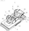
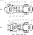
- FIGS. 1 to 25 illustrate a rehabilitation exercise device 1 for upper and lower limbs according to an embodiment of the present disclosure.
- the rehabilitation exercise device 1 includes a rehabilitation exercise unit 3 and a holder 5 for supporting the rehabilitation exercise unit 3.
- the rehabilitation exercise unit 3 may include: a first support 310 for supporting a user's hand or foot; a second support 320 for supporting a user's forearm or calf; a pair of first hinges 311 and 312 for rotatably connecting the first support 310 and the second support 320 to each other; a third support 330 for supporting a user's upper arm or thigh; and a pair of second hinges 331 and 332 for rotatably connecting the second support 320 and the third support 330 to each other.
- the holder 5 includes a base plate 510, and a mounting plate 520 on which the rehabilitation exercise unit 3 is mounted.
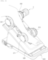
- the base plate 510 and the mounting plate 520 adopt a link-mechanism that converts horizontal motion into vertical motion.
- the link-mechanism is such that a first side of the mounting plate 520 is installed on the base plate 510 to be horizontally movable along a plate surface thereof, an intermediate region of the mounting plate 520 is connected to a first side of a link member 530, and a second side of the link member 530 is rotatably installed on the base plate 510.
- FIG. 1 in a state in which the mounting plate 520 is folded to the base plate 510, as illustrated in FIG. 3 , upper limb rehabilitation exercise is performed.
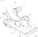
- FIG. 2 in a state in which the mounting plate 520 is erected at a certain angle from the base plate 510 by the link mechanism, as illustrated in FIG. 4 , lower limb rehabilitation exercise is performed.
- angle adjustment between the mounting plate 520 and the base plate 510, and angle fixing and releasing will be described later.
- the rehabilitation exercise unit 3 includes a distance adjustment part for adjusting the distance between the first support 310 and the third support 330 by adjusting the length of the second support 320 according to application in an upper or lower limb, and the length of a rehabilitation patient's upper or lower limb.
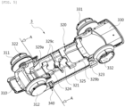
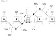
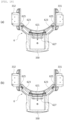
- the distance adjustment part of the rehabilitation exercise unit 3 according to the present disclosure will be described with reference to FIGS. 5 to 8 .
- the rehabilitation exercise unit 3 adopts a stacked slide-crank structure to the second support 320 so that the length of the second support 320 supporting the forearm or the calf is adjusted.
- the second support 320 may include a first fixing plate 322, a second fixing plate 323, a first moving plate 324, a second moving plate 325, and a hinge shaft 321.
- the first fixing plate 322 is connected to the pair of first hinges 311 and 312 to be rotatably coupled to the first support 310.
- the second fixing plate 323 is connected to the pair of second hinges 331 and 332 to be rotatably coupled to the third support 330.
- the first moving plate 324 is provided between the first fixing plate 322 and the hinge shaft 321 and is movable reciprocally therebetween.
- the second moving plate 325 is provided between the second fixing plate 323 and the hinge shaft 321 and is movable reciprocally therebetween.
- the hinge shaft 321 is provided between the first fixing plate 322 and the second fixing plate 323.
- the distance adjustment part includes a first crank 326 and a second crank 327.
- the first crank 326 is rotatably connected to the first fixing plate 322 and the hinge shaft 321 to convert a rotary motion of the hinge shaft 321 into a linear motion of the first fixing plate 322.
- the first crank 326 includes a first adjustment link 326a, a second adjustment link 326b, and a first connection link 326c.
- the first adjustment link 326a is rotatably coupled to the hinge shaft 321.
- the second adjustment link 326b has a first side rotatably coupled to the first adjustment link 326a, and a second side rotatably coupled to the first fixing plate 322.
- the first connection link 326c is rotatably coupled to the first moving plate 324 and an intermediate region of the first adjustment link 326a.
- the second crank 327 is rotatably connected to the second fixing plate 323 and the hinge shaft 321 to convert a rotary motion of the hinge shaft 321 into a linear motion of the second fixing plate 323.
- the second crank 327 includes a third adjustment link 327a, a fourth adjustment link 327b, and a second connection link 327c.
- the third adjustment link 327a is rotatably coupled to the hinge shaft 321.
- the third adjustment link 327a is disposed opposite to the first adjustment link 326a at an angle of 180 degrees.
- the fourth adjustment link 327b has a first side rotatably coupled to the third adjustment link 327a, and a second side rotatably coupled to the second fixing plate 323.
- the fourth adjustment link 327b is disposed opposite to the second adjustment link 326b.
- the second connection link 327c is rotatably coupled to the second moving plate 325 and an intermediate region of the third adjustment link 327a.
- the second connection link 327c is disposed opposite to the first connection link 326c.
- first guide rods 329a reciprocating movement of the first moving plate 324 is guided by a pair of first guide rods 329a extending in length from the first fixing plate 322 toward the first moving plate 324.
- reciprocating movement of the first moving plate 324 is guided by a pair of third guide rods 329c extending in length from the hinge shaft 321 toward the first moving plate 324.
- first guide rods 329a and the third guide rods 329c are provided in pairs, respectively, but the present disclosure is not limited thereto.
- at least one first guide rod 329a and at least one third guide rod 329c may be provided.
- reciprocating movement of the second moving plate 325 is guided by a pair of second guide rods 329b extending in length from the second fixing plate 323 toward the second moving plate 325.
- reciprocating movement of the second moving plate 325 is guided by a pair of third guide rods 329c extending in length from the hinge shaft 321 toward the second moving plate 325.
- the second guide rods 329b and the third guide rods 329c are provided in pairs, respectively, but the present disclosure is not limited thereto.
- at least one second guide rod 329b and at least one third guide rod 329c may be provided.
- the slide-crank mechanism in which the first fixing plate 322 and the first moving plate 324, and the second fixing plate 323 and the second moving plate 325 are operated in conjunction with each other, respectively, so as to be mutually approached or spaced apart with respect to the hinge shaft 321, it is possible to adjust the length of the second support 320, thereby adjusting the distance between the first support 310 and the third support 330.
- the first fixing plate 322 and the first moving plate 324, and the second fixing plate 323 and the second moving plate 325 are operated in conjunction with each other, respectively, so as to be mutually approached or spaced apart with respect to the hinge shaft 321.
- first fixing plate 322 and the second fixing plate 323 are connected to each other by a pair of connection bars 328.
- connection bars 328 a side of each of the connection bars 328 is fixed to the second fixing plate 323, and the first fixing plate 322 is movably coupled to the connection bars 328, so that the first fixing plate 322 is approached to and spaced apart from the second fixing plate 323.
- a through-hole 322a (see FIG. 8 ) for allowing passage of each of the connection bars 328 therethrough may be formed in the first fixing plate 322, so that longitudinal movement of the first fixing plate 322 may be guided along the connection bar 238.
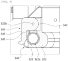
- a length stopper 340 may be installed on the first fixing plate 322 to restrain the longitudinal movement of the first fixing plate 322, for example, to limit relative movement of the first fixing plate 322 and the second fixing plate 323.
- a pair of length stoppers 340 are installed on the pair of connection bars 328, respectively.
- FIG. 8 is a sectional view illustrating the region of the length stopper 340 according to the present disclosure.
- the length stopper 340 may include a restraining lever 341 and a pressurizing member 345.
- the restraining lever 341 is rotatably installed on a rotary shaft 322b coupled to the first fixing plate 322.
- the restraining lever 341 includes a pusher 342 provided at a first end thereof to pressurize or release the pressurizing member 345, and a knob 343 provided at a second end thereof to rotate the pusher 342 to allow the pusher 342 to pressurize or release the pressurizing member 345.
- the pusher 342 has a semicircular arc shape having a predetermined radius of curvature, and is configured to be brought into contact with and spaced apart from the pressurizing member 345 by rotation.
- connection bar 238 is allowed to be moved inside the through-hole 322a, thereby allowing the movement of the first fixing plate 322 in the longitudinal direction along the connection bar 328.
- connection bar 328 is fixed to the second fixing plate 323, and the first fixing plate 322 is movably coupled to the connection bar 328, but the present disclosure is not limited thereto.
- the side of the connection bar 328 may be fixed to the first fixing plate 322, and the second fixing plate 323 may be movably coupled to the connection bar 328.
- the restraining lever 341 is provided on the second fixing plate 323.
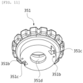
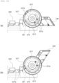
- FIGS. 9 to 12 are views illustrating an example of a structure for restraining longitudinal movement of a second support 320 according to another embodiment of the present disclosure.
- a rehabilitation exercise unit 3 may include a rotation stopper 350 provided on a hinge shaft 321 to limit relative movement of a first fixing plate 322 and a second fixing plate 323.
- the second support 320 has a slide-crank structure in adjusting a longitudinal length thereof, which includes rotation of the hinge shaft 321.
- the rotation stopper 350 restrains the rotation of the hinge shaft 321 to maintain a predetermined length.
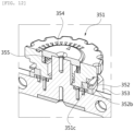
- the rotation stopper 350 includes a restraining dial 351, a shaft body 353 for forming the hinge shaft 321, a shaft column 354 protruding upward from the shaft body 353, and a shaft plate 352 rotated around the shaft body 354 and connected to the first adjustment link 326a and the third adjustment link 327a to rotate the first adjustment link 326a and the third adjustment link 327a with respect to the shaft body 353.
- the restraining dial 351 includes a restraining pin 351a and a catching recess 351c.
- the restraining pin 351c is formed by protruding from an end of the restraining dial 351 oriented toward the shaft body 353, and is inserted into or released from any one selected from among a plurality of restraining holes 352a which will be described later.
- the catching recess 351c is depressed in a region of the end of the restraining dial 351 oriented toward the shaft body 353, at a position spaced from the restraining pin 351a.
- a pair of catching recesses 351c are provided opposite to each other.
- the plurality of restraining holes 352a are formed in the shaft body 353 at a predetermined interval along the circumferential direction of the shaft column 354.
- the shaft plate 352 has a circular ring shape.
- the shaft plate 352 is configured such that the first adjustment link 326a and the third adjustment link 327a are connected to an outer circumference thereof, and the restraining dial 351 is rotatably provided on an inner circumference thereof.
- the shaft plate 352 has a pair of catching protrusions 352b protruding from a region of the inner circumference thereof, and connecting the restraining dial 351 to the shaft plate 352 by being caught by the catching recesses 351c of the restraining dial 351.
- the elastic member 355 is provided between the shaft column 354 and the restraining dial 351, and generates elastic force acting on the restraining dial 351 so that the restraining pin 351a is inserted into the selected restraining hole 352a.
- the user adjusts the length by pulling the restraining dial 351 upward so that the restraining dial 351 ascends from the shaft body 353 to a position where the restraining pin 351a is separated from the restraining hole 352a. Then, when the second support 320 is adjusted to a desired length, the user releases the restraining dial 351 so that the restraining dial 351 descends toward the shaft body 353 by the elastic force of the elastic member 355, and at the same time, the restraining pin 351a is inserted into the restraining hole 352a at a corresponding position.
- the shaft plate 352 when the restraining pin 351a is inserted into the restraining hole 352a, the shaft plate 352 is not rotated with respect to the shaft body 353, so that the length of the second support 320 is not allowed to be adjusted.
- the catching protrusions 352b of the shaft plate 352 are caught by the catching recesses 351c of the restraining dial 351, so that the restraining dial 351 is prevented from being rotated around the shaft column 354.
- reference numeral 351b denotes a pin insertion portion into which the restraining pin 351a is inserted and fixed
- reference numeral 351d denotes a shaft through-hole through which the shaft column 354 passes and fixed.
- FIG. 10 illustrates a state in which the restraining pin 351a is inserted in the restraining hole 352a in a state of being released from the restraining dial 351.
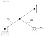
- the holder 5 may include the base plate 510, the mounting plate 520, and the link member 530. According to this configuration, a link mechanism as illustrated in FIG. 14 is implemented.
- the opposite sides of the link member 530 are rotatably coupled to the base plate 510 and the mounting plate 520, respectively.
- the first side (i.e., in the direction of the first support 510) of the mounting plate 520 is coupled to the base plate 510 to be horizontally movable along the plate surface thereof, and the first side of the link member 530 is rotatably coupled to the intermediate region of the mounting plate 520.
- a second side of the mounting plate 520 is approached to and spaced apart from the base plate 510 in the vertical direction by the link mechanism, so that angle adjustment is implemented as illustrated in FIGS. 1 and 2 .
- the second side of the link member 530 is rotatably coupled to a fixing shaft 531 provided on the base plate 510, so that when the first side of the mounting plate 520 moves in the horizontal direction, the angle of the mounting plate 520 is adjusted by rotation of the opposite sides of the link member 530.
- a pair of extension brackets 521 are installed opposite at the first side of the mounting plate 520 by extending parallel toward the third support 330.
- First ends of the pair of extension brackets 521 for example, first ends thereof oriented toward the first support 310, are rotatably coupled to the mounting plate 520.
- Second ends of the pair of extension brackets 521 for example, second ends thereof oriented toward the third support 330, are connected to each other by a connection rod 522.
- a catching plate 511 is installed inside the base plate 510, with a plurality of catching protrusions 512 formed thereon along the longitudinal direction and allowing the connection rod 522 to be caught thereby in response to the angle between the mounting plate 520 and the base plate 510.
- the plurality of catching protrusions 512 are formed at a predetermined interval along the longitudinal direction of the pair of extension brackets 521, so that the connection rod 522 is selectively caught by the catching protrusions 512.
- the connection rod 522 is caught by any one of the catching protrusions 512, so that the inclination angle is maintained at a predetermined angle.
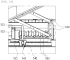
- the holder 5 may include a fixing unit 540 for fixing the connection rod 522 to maintain the connection rod 522 caught by any one of the catching protrusions 512.
- the fixing unit 540 may include a pair of unit bodies 541, a pair of operating levers 542, a pair of interlocking levers 543, and a pair of interlocking brackets 522a, as shown in FIGS. 15 and 16 .
- the unit bodies 541 are reciprocally moved along the base plate 510 in conjunction with the connection rod 522 in response to adjustment of the angle between the base plate 510 and the mounting plate 520.
- the interlocking levers 543 are provided inside the base plate 510, and are rotatably coupled to the unit bodies 541 so as to be rotated in conjunction with rotation of the operating levers 542.
- the interlocking brackets 522a are provided on opposite edges of the connection rod 522 to be oriented toward the interlocking levers 543, and are pressurized or released in response to rotation of the interlocking levers 543.
- the interlocking brackets 522a are connected to the connection rod 522 by connecting brackets 522b.
- connection rod 522 is limited from being moved upward, and thus the connection rod 522 is prevented from being released from the catching protrusion 512 of the base plate 510.
- connection rod 522 by removing or fixing the connection rod 522 from or into the catching protrusion 512 through the operation of the operating levers 542 outside the base plate 510, a safety accident that may occur due to an operation of lifting the connection rod 522 by inserting a hand between the mounting plate 520 and the base plate 510 is prevented from occurring.
- connection rod 522 by releasing the connection rod 522 from the catching protrusion 512, as illustrated in FIG. 3 , in a state in which the mounting plate 520 is folded to the base plate 510, upper limb rehabilitation exercise is performed.
- connection rod 522 by fixing the connection rod 522 to the catching protrusion 512, as illustrated in FIG. 4 , in a state in which the mounting plate 520 is erected from the base plate 510 at a predetermined angle, lower limb rehabilitation exercise is performed.
- rehabilitation exercise is performed by simply adjusting a mounting angle of the upper or lower limb with respect to the base plate 510 seated on the floor.
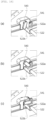
- FIGS. 27 and 28 illustrate a fixing unit 540a having a different shape from the fixing unit 540 described above.
- a plurality of auxiliary catching protrusions 523 are formed on a side of the base plate 510 along the longitudinal direction of the base plate 510, for example, in a parallel relationship to the plurality of catching protrusions 512.
- the plurality of auxiliary catching protrusions 523 have a continuous wave shape with valleys and ridges, and are arranged at the same pitch as the plurality of catching protrusions 512.
- a unit body 541 is selectively mounted on the plurality of auxiliary catching protrusions 523.
- a plurality of catching pins 524 are provided at positions corresponding to the valleys of the auxiliary catching protrusions 523.
- the plurality of catching pins 1524 are arranged at the same pitch as the auxiliary catching protrusions 523, and protrude from the side of the base plate 510.
- an interlocking lever 543a rotated in conjunction with rotation of an operating lever 542 has a ring-shaped free end.
- the interlocking lever 543a is provided outside the base plate 510, and is rotatably coupled to the unit body 541.
- the interlocking lever 543a As the interlocking lever 543a is rotated in conjunction with rotation of the operating lever 542, the interlocking lever 543a is caught by or released from a selected catching pin 524.
- the unit body 541 is connected to the connection rod 522 by a connecting bracket 522b.
- rehabilitation exercise is performed by simply adjusting the mounting angle of the upper or lower limb with respect to the base plate 510 seated on the floor.
- the drive module 7 may be selectively couple to any one of the pair of first hinges 311 and 312 and the pair of second hinges 331 and 332.
- the drive module 7 in the case of the upper limb, when the drive module 7 is mounted on any one of the first hinges 311 and 312, wrist rehabilitation exercise is possible.
- the drive module 7 is mounted on any one of the second hinges 331 and 332, elbow joint rehabilitation exercise is possible.
- a mounting position of the drive module 7 may be determined according to rehabilitation of a left or right upper limb.
- the drive module 7 may be selectively mounted according to rehabilitation of a right or left upper limb.
- the wrist motion when the wrist motion is performed in the state that the drive module 7 is couple to the first hinge 311 or 312, that is, when the first support 310 and the second support 320 are relatively rotated to each other, the second support 320 and the third support 330 need to be maintained fixed angle.
- the rehabilitation exercise device 1 may include an angle adjustment part 6 for adjusting an angle between the second support 320 and the third support 330.
- the angle adjustment part 6 includes a pair of rotary plates 611, a plurality of fixing holes 613, an angle fixing lever 621, a pair of first transmission links 623, and a pair of second transmission links 625.
- the pair of rotary plates 611 have a disc shape, are provided integrally with the third support 330 so as to be rotated independently of the pair of second hinges 331 and 332, and are shafted to the pair of second hinges 331 and 332. Therefore, the second hinges 331 and 332 of the rehabilitation exercise device 1 according to the present disclosure are rotated independently of the third support 330, and the second support 320 is coupled to the second hinges 331 and 332 to be rotatable relative thereto.
- the second hinges 331 and 332 are fixed to the mounting plate 520.
- the plurality of fixing holes 613 are formed at a predetermined interval along the circumferential direction of each of the rotary plates 611.
- the plurality of fixing holes 613 are inclined at a predetermined angle with respect to the radial direction of the rotary plate 611 in consideration of the radius of rotation of the second transmission links 625 rotated in response to the operation of the angle fixing lever 621 which will be described later.
- the angle fixing lever 621 is provided between the pair of second hinges 331 and 332, and is reciprocally moved relative to the first support 310. As illustrated in FIG. 17 , the angle fixing lever 621 is located under the third support 330.
- the pair of first transmission links 623 are rotatably coupled to opposite sides of the angle fixing lever 621, respectively.
- a first side of each of the pair of second transmission links 625 is rotatably coupled to an associated one of the pair of first transmission links 623, and a second side of each of the pair of second transmission links 625 is selectively inserted into or released from a selected fixing hole 613, so that rotation of the pair of rotary plates 611 are restrained or released.
- FIG. 18A illustrates a position where the angle is fixed
- FIG. 18B illustrates a position where the angle is released.
- An elastic member 627 such as a spring, may be provided on the angle fixing lever 621 to pressurize the angle fixing lever 621 to the position where the angle is fixed.
- the elastic member 627 generates an elastic force acting on the angle fixing lever 621 so that the second transmission links 625 are inserted into the selected fixing holes 613.
- the rotary plate 611 may have a first rotation guide hole 615 and a second rotation guide hole 617 formed in a semicircular arc shape along the circumferential direction.
- the first rotation guide hole 615 and the second rotation guide hole 617 may have semicircular arc shapes facing each other with the rotation center of each of the second hinges 331 and 332 interposed therebetween.
- a first rotation guide protrusion 331a and a second rotation guide protrusion 331b protruding from each of the second hinges 331 and 332 are inserted into and moved along the first rotation guide hole 615 and the second rotation guide hole 617, so that rotation between the second support 320 and the third support 330 is guided around the second hinges 331 and 332.
- the rotation angle between the second support 320 and the third support 330 may be restrained within a range of about 180 degrees by the semicircular arc-shaped first rotation guide hole 615 and second rotation guide hole 617.
- rehabilitation is performed by adjusting the angle between the second support 320 and the third support 330.
- the drive module 7 is selectively mounted on any one of the pair of first hinges 311 and 312 and the pair of second hinges 331 and 332 to pivot the first support 310 or the second support 320.
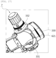
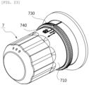
- the drive module 7 may include a body housing 710 in which components such as a drive motor, a printed circuit board, etc. are accommodated, a drive shaft 720 to which a rotary shaft of the drive motor is connected, and a ring member 730 for allowing mounting and fixing of the drive module 7 on the first hinges 311 and 312 or the second hinges 331 and 332.
- a ring coupling portion 751 is formed on each of the first hinges 311 and 312 or each of the second hinges 331 and 332.
- the drive module 7 is mounted on the second hinge 332 located on the right side as viewed from the first support 310 to the third support 330 in FIG. 1 . Therefore, for convenience of explanation, the second hinge 332 located on the right side is hereinafter referred to as a right second hinge 332.
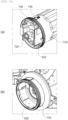
- a plurality of mounting protrusions 731 are formed on an inside of the ring member 730 at a predetermined interval along the circumferential direction of the ring member 730, and a ring coupling portion 751 to which the ring member 730 of the drive module 7 is coupled is provided circumferentially around an opening of the right second hinge 332.
- a plurality of catching portions 753 may be formed in the ring coupling portion 751 corresponding to the mounting protrusions 731.
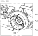
- a catching lever 740 is provided on the body housing 710a to restrain rotation of the ring member 730 by being inserted into the ring member 730, so that after rotating the ring member 730, the catching lever 740 is pushed and inserted into the ring member 730 to thereby prevent rotation of the ring member 730.
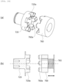
- the right second hinge 332 includes a hinge shaft 760a with which a drive shaft 720a of the drive module 7 is meshed.
- the drive shaft 720a and the hinge shaft 760a respectively include pluralities of jaws 720b and 760b that circumferentially alternately protrude to face each other.
- the respective jaws 720b and 760b of the driving shaft 720a and the hinge shaft 760a are meshed with each other, so that a rotational force of the drive module 7 is transmitted to the right second hinge 322 through the hinge shaft 760b.
- the hinge shaft 760a of the right second hinge 322 is connected to the second support 330.
- any one of the drive shaft 720a and the hinge shaft 760a includes an elastic member 765a, such as a spring, for generating an elastic force acting on the remaining opposite one to be pressurized, so that the drive shaft 720a and the hinge shaft 760a are firmly connected to each other.
- an elastic member 765a such as a spring
- each of the jaws 720b and 760b of the drive shaft 720a and the hinge shaft 760a is configured such that opposite sides thereof are inclined, so that the drive shaft 720a and the hinge shaft 760a are easily coupled to each other even when slight misalignment occurs during initial coupling.
- the rehabilitation exercise device 1 allows the drive module 7 to be easily mounted on and removed from a desired hinge, thereby enabling the user to perform a rehabilitation exercise with improved convenience.
- a rotation restraining part 770 may be provided to restrain rotation of the first hinges 311 and 312 or the second hinges 331 and 332.
- the rotation restraining part 770 is provided on each of the pair of first hinges 311 and 312.
- the rotation restraining part 770 may include a rotary gear plate 771 rotated in conjunction with any one of the first support 310 and the second support 320, and a gear restraining member 775 installed on any one of the first support 310 and the second support 320.
- the rotary gear plate 771 may have gear teeth circumferentially formed along an end thereof, and the gear restraining member 775 may also have gear teeth formed at an end thereof.
- rotation of the first support 310 and the second support 320 may be restrained such that when the gear restraining member 775 is meshed with the rotary gear plate 771 as illustrated in FIG. 25A , the rotary gear plate 771 is not rotated, and when the gear restraining member 775 is released from the rotary gear plate 771 as illustrated in FIG. 25B , the rotary gear plate 771 is rotated.
- the second support 320 performs a pivoting motion by a rotational force of the drive module 7, whereas the first support 310 is limited in pivoting motion, so that the user can exercise an elbow joint while a wrist joint is not moved.
- the first support 310 performs a pivoting motion by a rotational force of the drive module 7, whereas the second support 320 is limited in pivoting motion, so that the user can exercise the wrist joint while the elbow joint is not moved.
- the user can selectively perform wrist joint or elbow joint rehabilitation exercises.
- the rehabilitation exercise device 1 may enable the user to perform rehabilitation by selectively mounting the drive module 7 to each hinge in response to a position of the upper or lower limb to be exercised.
- the rehabilitation exercise device 1 when the drive module 7 is mounted on the left first hinge 311 or the left second hinge 331, the rehabilitation exercise device 1 according to the embodiment of the present disclosure is worn on a right upper limb to exercise, without causing interference of the drive module 7 with a user's torso.
- the drive module 7 when the drive module 7 is mounted on the left first hinge 311, exercise of a right wrist joint is possible.
- exercise of a right elbow joint is possible.
- the rehabilitation exercise device 1 When the drive module 7 is mounted on the right first hinge 312 or the right second hinge 332, the rehabilitation exercise device 1 according to the embodiment of the present disclosure is worn on a left upper limb to exercise, without causing interference of the drive module 7 with the user's torso.
- the drive module 7 when the drive module 7 is mounted on the right first hinge 312, exercise of a left wrist joint is possible.
- the drive module 7 is mounted on the right second hinge 332, exercise of a left elbow joint is possible.
- a tag 920 may be installed on each of the first hinges 311 and 312 and the second hinges 331 and 332 at a position where tagging is possible when the drive module 7 is coupled to the first hinges 311 and 312 or the second hinges 331 and 332.
- a reader 910 may be installed in the drive module 7, the reader being capable of tagging the tag 920 when the drive module 7 is coupled to the first hinges 311 and 312 or the second hinges 331 and 332.
- the tag 920 and the reader 910 may communicate with each other through radio frequency (RF) communication or near field communication (NFC).
- RF radio frequency
- NFC near field communication
- the present disclosure can find application in a rehabilitation exercise device for rehabilitation of a patient's upper or lower limb.
Landscapes
- Health & Medical Sciences (AREA)
- Epidemiology (AREA)
- Pain & Pain Management (AREA)
- Physical Education & Sports Medicine (AREA)
- Rehabilitation Therapy (AREA)
- Life Sciences & Earth Sciences (AREA)
- Animal Behavior & Ethology (AREA)
- General Health & Medical Sciences (AREA)
- Public Health (AREA)
- Veterinary Medicine (AREA)
- Rehabilitation Tools (AREA)
Claims (13)
- Rehabilitationsübungsgerät (1) für obere und untere Gliedmaßen, wobei das Rehabilitationsübungsgerät (1) Folgendes umfasst:eine erste Stütze (310), die die Hand oder den Fuß eines Benutzers stützt;eine zweite Stütze (320), die den Unterarm oder die Wade eines Benutzers stützt;ein Paar erster Scharniere (311), die die erste Stütze (310) und die zweite Stütze (320) drehbar miteinander verbinden;eine dritte Stütze (330), die den Oberarm oder Oberschenkel eines Benutzers stützt;ein Paar zweiter Scharniere (331), die die zweite Stütze (320) und die dritte Stütze (330) drehbar miteinander verbinden; undein Abstandseinstellteil, das so konfiguriert ist, dass es einen Abstand zwischen der ersten Stütze (310) und der dritten Stütze (330) durch Einstellen der Länge der zweiten Stütze (320) einstellt,wobei die zweite Stütze (320) Folgendes umfasst:eine erste Befestigungsplatte (322), die mit dem Paar erster Scharniere (311) verbunden ist, um drehbar mit der ersten Stütze (310) verbunden zu werden;eine zweite Befestigungsplatte (323), die mit dem Paar zweiter Scharniere (331) verbunden ist, um drehbar mit dem dritten Träger (330) verbunden zu werden, und so konfiguriert ist, dass sie durch das Abstandseinstellteil in Bezug auf die erste Befestigungsplatte (322) einander angenähert oder voneinander beabstandet werden kann;eine Scharnierwelle (321), die zwischen der ersten Befestigungsplatte (322) und der zweiten Befestigungsplatte (323) vorgesehen ist;eine erste bewegliche Platte (324), die zwischen der ersten Befestigungsplatte (322) und der Gelenkwelle (321) vorgesehen ist und so konfiguriert ist, dass sie zwischen diesen hin- und herbewegt werden kann; undeine zweite bewegliche Platte (325), die zwischen der zweiten Befestigungsplatte (323) und der Gelenkwelle (321) vorgesehen ist und so konfiguriert ist, dass sie zwischen diesen hin- und herbewegt werden kann (1) , wobei das Abstandseinstellteil umfasst:eine erste Kurbel (326), die drehbar mit der ersten Befestigungsplatte (322) und der Scharnierwelle (321) verbunden ist und so konfiguriert ist, dass sie eine Drehbewegung der Scharnierwelle (321) in eine lineare Bewegung der ersten Befestigungsplatte (322) umwandelt; undeine zweite Kurbel (327), die drehbar mit der zweiten Befestigungsplatte (323) und der Gelenkwelle (321) verbunden ist und so konfiguriert ist, dass sie die Drehbewegung der Gelenkwelle (321) in eine lineare Bewegung der zweiten Befestigungsplatte (323) umwandelt.
- Rehabilitationsübungsgerät nach Anspruch 1, wobei die erste Kurbel (326) Folgendes umfasst:ein erstes Einstellglied, das drehbar mit der Gelenkwelle (321) verbunden ist; undein zweites Einstellglied, das eine erste Seite, die drehbar mit dem ersten Einstellglied verbunden ist, und eine zweite Seite, die drehbar mit der ersten Befestigungsplatte (322) verbunden ist, aufweist, unddie zweite Kurbel (327) umfasst:ein drittes Einstellglied, das drehbar mit der Gelenkwelle (321) verbunden ist; undein viertes Einstellglied mit einer ersten Seite, die drehbar mit dem dritten Einstellglied verbunden ist, und einer zweiten Seite, die drehbar mit der zweiten Befestigungsplatte (323) verbunden ist.
- Rehabilitationsübungsgerät nach Anspruch 2, wobei die erste Kurbel (326) ferner ein erstes Verbindungsglied umfasst, das drehbar mit der ersten beweglichen Platte (324) und dem ersten Einstellglied verbunden ist; und
die zweite Kurbel (327) ferner ein zweites Verbindungsglied umfasst, das drehbar mit der zweiten beweglichen Platte (325) und dem dritten Einstellglied verbunden ist. - Rehabilitationsübungsgerät nach Anspruch 1, ferner umfassend:eine Verbindungsstange (238), die die erste Befestigungsplatte (322) und die zweite Befestigungsplatte (323) miteinander verbindet,wobei entweder die erste Befestigungsplatte (322) oder die zweite Befestigungsplatte (323) an der Verbindungsstange (238) befestigt ist und die verbleibende Platte, d. h. entweder die erste Befestigungsplatte (322) oder die zweite Befestigungsplatte (323), mit der Verbindungsstange (238) gekoppelt ist, so dass sie entlang dieser beweglich ist.
- Rehabilitationsübungsgerät nach Anspruch 4, das ferner Folgendes umfasst:
einen Längenanschlag (340), der an der Verbindungsstange (238) vorgesehen ist und so konfiguriert ist, dass er die relative Bewegung der ersten Befestigungsplatte (322) und der zweiten Befestigungsplatte (323) begrenzt. - Rehabilitationsübungsgerät nach Anspruch 5, wobei der Längenanschlag (340) Folgendes umfasst:einen Rückhaltehebel (341), der drehbar an einer der ersten Befestigungsplatte (322) und der zweiten Befestigungsplatte (323) vorgesehen ist, die so gekoppelt sind, dass sie entlang der Verbindungsstange (238) beweglich sind; undein Druckelement (345), das auf einer Rotationsbahn des Rückhaltehebels (341) vorgesehen ist und so konfiguriert ist, dass es die Verbindungsstange (238) unter Druck setzt oder freigibt, indem es sich der Verbindungsstange (238) nähert oder von dieser entfernt, und zwar als Reaktion auf die Drehung des Rückhaltehebels (341).
- Rehabilitationsübungsgerät nach Anspruch 6, wobei der Rückhaltehebel (341) Folgendes umfasst:einen Drücker, der an einem ersten Ende davon vorgesehen ist und so konfiguriert ist, dass er das Druckelement (345) unter Druck setzt oder freigibt; undeinen Knopf, der an einem zweiten Ende davon vorgesehen ist und so konfiguriert ist, dass er den Drücker dreht, damit der Drücker das Druckelement (345) unter Druck setzen oder freigeben kann.
- Rehabilitationsübungsgerät (1) nach Anspruch 2, das ferner Folgendes umfasst:
einen Rotationsstopper (350), der auf der Gelenkwelle (321) vorgesehen ist und so konfiguriert ist, dass er die relative Bewegung der ersten Befestigungsplatte (322) und der zweiten Befestigungsplatte (323) begrenzt. - Rehabilitationsübungsgerät nach Anspruch 8, wobei der Rotationsstopper (350) Folgendes umfasst:eine Rückhaltescheibe (351);einen Wellenkörper (353), der die Gelenkwelle (321) bildet;eine Wellensäule (354), die vom Wellenkörper (353) nach oben vorsteht und mit der die Rückhaltescheibe (351) drehbar und anhebbar verbunden ist; undeine Wellenplatte (352), die so konfiguriert ist, dass sie um den Wellenkörper (353) gedreht werden kann, und mit dem ersten Einstellglied und dem dritten Einstellglied verbunden ist,wobei eine Vielzahl von Rückhaltelöchern in dem Wellenkörper (353) in einem vorbestimmten Abstand entlang einer Umfangsrichtung der Wellensäule (354) ausgebildet sind;die Rückhaltescheibe (351) einen Rückhaltestift umfasst, der von einem Ende davon vorsteht, das zum Wellenkörper (353) hin ausgerichtet ist, und so konfiguriert ist, dass er in eines der mehreren Rückhaltelöcher eingeführt oder aus diesem gelöst werden kann, sowie eine Fangaussparung, die in einem Bereich des Endes der Rückhaltescheibe (351) vertieft ist, der zum Wellenkörper (353) hin ausgerichtet ist, an einer Position, die vom Rückhaltestift beabstandet ist; unddie Wellenplatte (352) einen Fangvorsprung umfasst, der so konfiguriert ist, dass er die Rückhaltescheibe (351) mit der Wellenplatte (352) verbindet, indem er von der Fangaussparung der Rückhaltescheibe (351) erfasst wird.
- Rehabilitationsübungsgerät nach Anspruch 9, wobei, wenn der Rückhaltestift in das Rückhalteloch eingeführt wird, der Fangvorsprung von der Fangaussparung erfasst wird, um zu verhindern, dass die Rückhaltescheibe (351) um die Schaftsäule (354) gedreht wird; und
wenn der Rückhaltestift aus dem Rückhalteloch gelöst wird, der Fangvorsprung weiterhin von der Fangaussparung gefangen gehalten wird, wodurch die Rückhaltescheibe (351) um die Schaftsäule (354) vorwärts und rückwärts drehbar ist, so dass die erste Befestigungsplatte (322) und die zweite Befestigungsplatte (323) in Bezug auf den Schaftkörper (353) einander angenähert oder voneinander beabstandet werden. - Rehabilitationsübungsgerät nach Anspruch 9, das ferner Folgendes umfasst:
ein elastisches Element (627) (355) (355), das zwischen der Schaftsäule (354) und der Rückhalteeinrichtung (351) vorgesehen ist und so konfiguriert ist, dass es eine elastische Kraft erzeugt, die auf die Rückhalteeinrichtung (351) wirkt, so dass der Rückhaltebolzen in das ausgewählte Rückhalteloch eingeführt wird. - Rehabilitationsübungsgerät nach Anspruch 1, ferner umfassend:eine erste Führungsstange, die sich in Längsrichtung von der ersten Befestigungsplatte (322) zur ersten beweglichen Platte (324) erstreckt und so konfiguriert ist, dass sie die Hin- und Herbewegung der ersten beweglichen Platte (324) führt; undeine zweite Führungsstange, die sich in Längsrichtung von der zweiten Befestigungsplatte (323) zur zweiten beweglichen Platte (325) erstreckt und so konfiguriert ist, dass sie die Hin- und Herbewegung der zweiten beweglichen Platte (325) führt.
- Rehabilitationsübungsgerät nach Anspruch 12, ferner umfassend:
ein Paar dritter Führungsstangen, die sich in Längsrichtung von der Gelenkwelle (321) zur ersten beweglichen Platte (324) bzw. zur zweiten beweglichen Platte (325) erstrecken und so konfiguriert sind, dass sie die Hin- und Herbewegung der ersten beweglichen Platte (324) bzw. der zweiten beweglichen Platte (325) führen.
Applications Claiming Priority (4)
| Application Number | Priority Date | Filing Date | Title |
|---|---|---|---|
| KR1020190146775A KR102246049B1 (ko) | 2019-11-15 | 2019-11-15 | 상지 및 하지용 재활 운동 장치 |
| KR20200022968 | 2020-02-25 | ||
| KR1020200043956A KR102352602B1 (ko) | 2020-02-25 | 2020-04-10 | 상지 및 하지용 재활 운동 장치 |
| PCT/KR2020/015123 WO2021096129A1 (ko) | 2019-11-15 | 2020-11-02 | 상지 및 하지용 재활 운동 장치 |
Publications (3)
| Publication Number | Publication Date |
|---|---|
| EP3984513A1 EP3984513A1 (de) | 2022-04-20 |
| EP3984513A4 EP3984513A4 (de) | 2023-08-30 |
| EP3984513B1 true EP3984513B1 (de) | 2025-01-08 |
Family
ID=75912849
Family Applications (1)
| Application Number | Title | Priority Date | Filing Date |
|---|---|---|---|
| EP20888679.6A Active EP3984513B1 (de) | 2019-11-15 | 2020-11-02 | Rehabilitationsübungsgerät für obere und untere gliedmassen |
Country Status (4)
| Country | Link |
|---|---|
| US (1) | US11903891B2 (de) |
| EP (1) | EP3984513B1 (de) |
| JP (1) | JP7231751B2 (de) |
| WO (1) | WO2021096129A1 (de) |
Families Citing this family (75)
| Publication number | Priority date | Publication date | Assignee | Title |
|---|---|---|---|---|
| US12029940B2 (en) | 2019-03-11 | 2024-07-09 | Rom Technologies, Inc. | Single sensor wearable device for monitoring joint extension and flexion |
| US11471729B2 (en) | 2019-03-11 | 2022-10-18 | Rom Technologies, Inc. | System, method and apparatus for a rehabilitation machine with a simulated flywheel |
| US11433276B2 (en) | 2019-05-10 | 2022-09-06 | Rehab2Fit Technologies, Inc. | Method and system for using artificial intelligence to independently adjust resistance of pedals based on leg strength |
| US11957956B2 (en) | 2019-05-10 | 2024-04-16 | Rehab2Fit Technologies, Inc. | System, method and apparatus for rehabilitation and exercise |
| US11801423B2 (en) | 2019-05-10 | 2023-10-31 | Rehab2Fit Technologies, Inc. | Method and system for using artificial intelligence to interact with a user of an exercise device during an exercise session |
| US12102878B2 (en) | 2019-05-10 | 2024-10-01 | Rehab2Fit Technologies, Inc. | Method and system for using artificial intelligence to determine a user's progress during interval training |
| US11904207B2 (en) | 2019-05-10 | 2024-02-20 | Rehab2Fit Technologies, Inc. | Method and system for using artificial intelligence to present a user interface representing a user's progress in various domains |
| US11957960B2 (en) | 2019-05-10 | 2024-04-16 | Rehab2Fit Technologies Inc. | Method and system for using artificial intelligence to adjust pedal resistance |
| US11833393B2 (en) | 2019-05-15 | 2023-12-05 | Rehab2Fit Technologies, Inc. | System and method for using an exercise machine to improve completion of an exercise |
| US11896540B2 (en) | 2019-06-24 | 2024-02-13 | Rehab2Fit Technologies, Inc. | Method and system for implementing an exercise protocol for osteogenesis and/or muscular hypertrophy |
| US12402804B2 (en) | 2019-09-17 | 2025-09-02 | Rom Technologies, Inc. | Wearable device for coupling to a user, and measuring and monitoring user activity |
| US11071597B2 (en) | 2019-10-03 | 2021-07-27 | Rom Technologies, Inc. | Telemedicine for orthopedic treatment |
| US12589279B2 (en) | 2019-10-03 | 2026-03-31 | Rom Technologies, Inc. | Systems and methods of using artificial intelligence and machine learning for generating an alignment plan capable of enabling the aligning of a user's body during a treatment session |
| US12191018B2 (en) | 2019-10-03 | 2025-01-07 | Rom Technologies, Inc. | System and method for using artificial intelligence in telemedicine-enabled hardware to optimize rehabilitative routines capable of enabling remote rehabilitative compliance |
| US12605613B2 (en) | 2022-05-04 | 2026-04-21 | Rom Technologies, Inc. | Systems and methods for using smart exercise devices to perform cardiovascular rehabilitation |
| US12176089B2 (en) | 2019-10-03 | 2024-12-24 | Rom Technologies, Inc. | System and method for using AI ML and telemedicine for cardio-oncologic rehabilitation via an electromechanical machine |
| US12020799B2 (en) | 2019-10-03 | 2024-06-25 | Rom Technologies, Inc. | Rowing machines, systems including rowing machines, and methods for using rowing machines to perform treatment plans for rehabilitation |
| US12224052B2 (en) | 2019-10-03 | 2025-02-11 | Rom Technologies, Inc. | System and method for using AI, machine learning and telemedicine for long-term care via an electromechanical machine |
| US11923065B2 (en) | 2019-10-03 | 2024-03-05 | Rom Technologies, Inc. | Systems and methods for using artificial intelligence and machine learning to detect abnormal heart rhythms of a user performing a treatment plan with an electromechanical machine |
| US12562243B2 (en) | 2019-10-03 | 2026-02-24 | Rom Technologies, Inc. | System and method for processing medical claims using biometric signatures |
| US12230381B2 (en) | 2019-10-03 | 2025-02-18 | Rom Technologies, Inc. | System and method for an enhanced healthcare professional user interface displaying measurement information for a plurality of users |
| US12539446B2 (en) | 2019-10-03 | 2026-02-03 | Rom Technologies, Inc. | Method and system for using sensors to optimize a user treatment plan in a telemedicine environment |
| US11075000B2 (en) | 2019-10-03 | 2021-07-27 | Rom Technologies, Inc. | Method and system for using virtual avatars associated with medical professionals during exercise sessions |
| US11270795B2 (en) | 2019-10-03 | 2022-03-08 | Rom Technologies, Inc. | Method and system for enabling physician-smart virtual conference rooms for use in a telehealth context |
| US12087426B2 (en) | 2019-10-03 | 2024-09-10 | Rom Technologies, Inc. | Systems and methods for using AI ML to predict, based on data analytics or big data, an optimal number or range of rehabilitation sessions for a user |
| US11087865B2 (en) | 2019-10-03 | 2021-08-10 | Rom Technologies, Inc. | System and method for use of treatment device to reduce pain medication dependency |
| US11317975B2 (en) | 2019-10-03 | 2022-05-03 | Rom Technologies, Inc. | Method and system for treating patients via telemedicine using sensor data from rehabilitation or exercise equipment |
| US12548656B2 (en) | 2019-10-03 | 2026-02-10 | Rom Technologies, Inc. | System and method for an enhanced patient user interface displaying real-time measurement information during a telemedicine session |
| US11325005B2 (en) | 2019-10-03 | 2022-05-10 | Rom Technologies, Inc. | Systems and methods for using machine learning to control an electromechanical device used for prehabilitation, rehabilitation, and/or exercise |
| US11955222B2 (en) | 2019-10-03 | 2024-04-09 | Rom Technologies, Inc. | System and method for determining, based on advanced metrics of actual performance of an electromechanical machine, medical procedure eligibility in order to ascertain survivability rates and measures of quality-of-life criteria |
| US11978559B2 (en) | 2019-10-03 | 2024-05-07 | Rom Technologies, Inc. | Systems and methods for remotely-enabled identification of a user infection |
| US12100499B2 (en) | 2020-08-06 | 2024-09-24 | Rom Technologies, Inc. | Method and system for using artificial intelligence and machine learning to create optimal treatment plans based on monetary value amount generated and/or patient outcome |
| US12478837B2 (en) | 2019-10-03 | 2025-11-25 | Rom Technologies, Inc. | Method and system for monitoring actual patient treatment progress using sensor data |
| US11265234B2 (en) | 2019-10-03 | 2022-03-01 | Rom Technologies, Inc. | System and method for transmitting data and ordering asynchronous data |
| US11955220B2 (en) | 2019-10-03 | 2024-04-09 | Rom Technologies, Inc. | System and method for using AI/ML and telemedicine for invasive surgical treatment to determine a cardiac treatment plan that uses an electromechanical machine |
| US12154672B2 (en) | 2019-10-03 | 2024-11-26 | Rom Technologies, Inc. | Method and system for implementing dynamic treatment environments based on patient information |
| US12220201B2 (en) | 2019-10-03 | 2025-02-11 | Rom Technologies, Inc. | Remote examination through augmented reality |
| US12420145B2 (en) | 2019-10-03 | 2025-09-23 | Rom Technologies, Inc. | Systems and methods of using artificial intelligence and machine learning for generating alignment plans to align a user with an imaging sensor during a treatment session |
| US12230382B2 (en) | 2019-10-03 | 2025-02-18 | Rom Technologies, Inc. | Systems and methods for using artificial intelligence and machine learning to predict a probability of an undesired medical event occurring during a treatment plan |
| US11915816B2 (en) | 2019-10-03 | 2024-02-27 | Rom Technologies, Inc. | Systems and methods of using artificial intelligence and machine learning in a telemedical environment to predict user disease states |
| US11515021B2 (en) | 2019-10-03 | 2022-11-29 | Rom Technologies, Inc. | Method and system to analytically optimize telehealth practice-based billing processes and revenue while enabling regulatory compliance |
| US20230245750A1 (en) | 2019-10-03 | 2023-08-03 | Rom Technologies, Inc. | Systems and methods for using elliptical machine to perform cardiovascular rehabilitation |
| US12427376B2 (en) | 2019-10-03 | 2025-09-30 | Rom Technologies, Inc. | Systems and methods for an artificial intelligence engine to optimize a peak performance |
| US11139060B2 (en) | 2019-10-03 | 2021-10-05 | Rom Technologies, Inc. | Method and system for creating an immersive enhanced reality-driven exercise experience for a user |
| US11955223B2 (en) | 2019-10-03 | 2024-04-09 | Rom Technologies, Inc. | System and method for using artificial intelligence and machine learning to provide an enhanced user interface presenting data pertaining to cardiac health, bariatric health, pulmonary health, and/or cardio-oncologic health for the purpose of performing preventative actions |
| US12469587B2 (en) | 2019-10-03 | 2025-11-11 | Rom Technologies, Inc. | Systems and methods for assigning healthcare professionals to remotely monitor users performing treatment plans on electromechanical machines |
| US12380984B2 (en) | 2019-10-03 | 2025-08-05 | Rom Technologies, Inc. | Systems and methods for using artificial intelligence and machine learning to generate treatment plans having dynamically tailored cardiac protocols for users to manage a state of an electromechanical machine |
| US11282608B2 (en) | 2019-10-03 | 2022-03-22 | Rom Technologies, Inc. | Method and system for using artificial intelligence and machine learning to provide recommendations to a healthcare provider in or near real-time during a telemedicine session |
| US12555667B2 (en) | 2019-10-03 | 2026-02-17 | Rom Technologies, Inc. | Systems and methods for using AI/ML and for cardiac and pulmonary treatment via an electromechanical machine related to urologic disorders and antecedents and sequelae of certain urologic surgeries |
| US11887717B2 (en) | 2019-10-03 | 2024-01-30 | Rom Technologies, Inc. | System and method for using AI, machine learning and telemedicine to perform pulmonary rehabilitation via an electromechanical machine |
| US11961603B2 (en) | 2019-10-03 | 2024-04-16 | Rom Technologies, Inc. | System and method for using AI ML and telemedicine to perform bariatric rehabilitation via an electromechanical machine |
| US11282604B2 (en) | 2019-10-03 | 2022-03-22 | Rom Technologies, Inc. | Method and system for use of telemedicine-enabled rehabilitative equipment for prediction of secondary disease |
| US11955221B2 (en) | 2019-10-03 | 2024-04-09 | Rom Technologies, Inc. | System and method for using AI/ML to generate treatment plans to stimulate preferred angiogenesis |
| US11101028B2 (en) | 2019-10-03 | 2021-08-24 | Rom Technologies, Inc. | Method and system using artificial intelligence to monitor user characteristics during a telemedicine session |
| US12020800B2 (en) | 2019-10-03 | 2024-06-25 | Rom Technologies, Inc. | System and method for using AI/ML and telemedicine to integrate rehabilitation for a plurality of comorbid conditions |
| US12150792B2 (en) | 2019-10-03 | 2024-11-26 | Rom Technologies, Inc. | Augmented reality placement of goniometer or other sensors |
| US11069436B2 (en) | 2019-10-03 | 2021-07-20 | Rom Technologies, Inc. | System and method for use of telemedicine-enabled rehabilitative hardware and for encouraging rehabilitative compliance through patient-based virtual shared sessions with patient-enabled mutual encouragement across simulated social networks |
| US11830601B2 (en) | 2019-10-03 | 2023-11-28 | Rom Technologies, Inc. | System and method for facilitating cardiac rehabilitation among eligible users |
| US12062425B2 (en) | 2019-10-03 | 2024-08-13 | Rom Technologies, Inc. | System and method for implementing a cardiac rehabilitation protocol by using artificial intelligence and standardized measurements |
| US12420143B1 (en) | 2019-10-03 | 2025-09-23 | Rom Technologies, Inc. | System and method for enabling residentially-based cardiac rehabilitation by using an electromechanical machine and educational content to mitigate risk factors and optimize user behavior |
| US11282599B2 (en) | 2019-10-03 | 2022-03-22 | Rom Technologies, Inc. | System and method for use of telemedicine-enabled rehabilitative hardware and for encouragement of rehabilitative compliance through patient-based virtual shared sessions |
| US11915815B2 (en) | 2019-10-03 | 2024-02-27 | Rom Technologies, Inc. | System and method for using artificial intelligence and machine learning and generic risk factors to improve cardiovascular health such that the need for additional cardiac interventions is mitigated |
| US12347543B2 (en) | 2019-10-03 | 2025-07-01 | Rom Technologies, Inc. | Systems and methods for using artificial intelligence to implement a cardio protocol via a relay-based system |
| US12327623B2 (en) | 2019-10-03 | 2025-06-10 | Rom Technologies, Inc. | System and method for processing medical claims |
| US12246222B2 (en) | 2019-10-03 | 2025-03-11 | Rom Technologies, Inc. | Method and system for using artificial intelligence to assign patients to cohorts and dynamically controlling a treatment apparatus based on the assignment during an adaptive telemedical session |
| US12562271B2 (en) | 2019-11-06 | 2026-02-24 | Rom Technologies, Inc. | System for remote treatment utilizing privacy controls |
| US11826613B2 (en) | 2019-10-21 | 2023-11-28 | Rom Technologies, Inc. | Persuasive motivation for orthopedic treatment |
| US12424319B2 (en) | 2019-11-06 | 2025-09-23 | Rom Technologies, Inc. | System for remote treatment utilizing privacy controls |
| US11107591B1 (en) | 2020-04-23 | 2021-08-31 | Rom Technologies, Inc. | Method and system for describing and recommending optimal treatment plans in adaptive telemedical or other contexts |
| CN115955937B (zh) | 2020-06-26 | 2025-09-09 | 罗姆科技股份有限公司 | 用于锚固电子装置并测量关节角度的系统、方法和设备 |
| US12515104B2 (en) | 2020-10-28 | 2026-01-06 | Rom Technologies, Inc. | Systems and methods for using machine learning to control a rehabilitation and exercise electromechanical device |
| US20220314072A1 (en) | 2021-03-30 | 2022-10-06 | Rehab2Fit Technologies, Inc. | Adjustment of exercise based on artificial intelligence, exercise plan, and user feedback |
| CN119034171B (zh) * | 2024-10-31 | 2025-03-25 | 温州职业技术学院 | 一种老年人踝关节扭伤康复锻炼装置及其使用方法 |
| CN119792015B (zh) * | 2025-01-06 | 2025-10-10 | 中国人民解放军陆军特色医学中心 | 一种肢体创伤辅助康复装置 |
| CN119587944B (zh) * | 2025-01-08 | 2025-10-10 | 中国人民解放军陆军军医大学第一附属医院 | 一种血管介入术后康复辅助装置 |
Family Cites Families (17)
| Publication number | Priority date | Publication date | Assignee | Title |
|---|---|---|---|---|
| US4930497A (en) * | 1989-01-23 | 1990-06-05 | Toronto Medical Corp. | Apparatus for imparting continuous passive motion to a lower limb |
| JP3174807B2 (ja) * | 1996-04-05 | 2001-06-11 | 株式会社エム・イー・システム | 関節連続受動運動訓練装置 |
| JP2002119555A (ja) * | 2000-10-13 | 2002-04-23 | Ribaafasshon:Kk | リハビリテーション装置 |
| JP4712627B2 (ja) * | 2006-07-10 | 2011-06-29 | 本田技研工業株式会社 | 歩行補助装置 |
| US7695416B2 (en) * | 2007-10-05 | 2010-04-13 | Jay John Weiner | Device and method for knee joint rehabilitation |
| KR100936621B1 (ko) * | 2008-03-20 | 2010-01-13 | 경희대학교 산학협력단 | 하지 운동 재활 기구 |
| AR071041A1 (es) * | 2009-03-25 | 2010-05-19 | Cardile Jorge | Dispositivo para la educacion y rehabilitacion de marcha y desarrollo de equilibrio |
| KR101059828B1 (ko) * | 2009-12-08 | 2011-08-29 | (주)케어테크 | 골절 환자용 회복운동장치 |
| CN101869526A (zh) * | 2010-06-07 | 2010-10-27 | 付风生 | 一种上肢康复训练机器人 |
| KR101163903B1 (ko) | 2010-08-13 | 2012-07-09 | 한국과학기술원 | 뇌졸중 환자의 상지 재활을 위한 외골격 로봇 |
| KR101227861B1 (ko) * | 2011-01-27 | 2013-01-31 | 근로복지공단 | 상지근력보조기구 |
| US9125789B2 (en) * | 2011-03-11 | 2015-09-08 | Felix M. Garcia | Knee extension assist device |
| CN103892987B (zh) * | 2012-12-25 | 2015-11-25 | 上海璟和技创机器人有限公司 | 一种下肢康复训练机器人 |
| KR101552507B1 (ko) * | 2013-08-13 | 2015-09-11 | 주식회사 에이치엔에이치 | 인체 롤링 타입 마사지기 |
| FR3046051B1 (fr) * | 2015-12-24 | 2020-11-13 | Sagem Defense Securite | Module de dos pour une structure d'exosquelette |
| KR101937012B1 (ko) * | 2017-02-02 | 2019-04-03 | 연세대학교 산학협력단 | 하지 관절 보조용 외골격 시스템 |
| JP7111463B2 (ja) * | 2017-12-15 | 2022-08-02 | サンコール株式会社 | 歩行動作補助装置 |
-
2020
- 2020-11-02 EP EP20888679.6A patent/EP3984513B1/de active Active
- 2020-11-02 US US17/059,413 patent/US11903891B2/en active Active
- 2020-11-02 JP JP2021546866A patent/JP7231751B2/ja active Active
- 2020-11-02 WO PCT/KR2020/015123 patent/WO2021096129A1/ko not_active Ceased
Also Published As
| Publication number | Publication date |
|---|---|
| JP2022521377A (ja) | 2022-04-07 |
| JP7231751B2 (ja) | 2023-03-01 |
| EP3984513A4 (de) | 2023-08-30 |
| WO2021096129A1 (ko) | 2021-05-20 |
| EP3984513A1 (de) | 2022-04-20 |
| US20220339052A1 (en) | 2022-10-27 |
| US11903891B2 (en) | 2024-02-20 |
Similar Documents
| Publication | Publication Date | Title |
|---|---|---|
| EP3984513B1 (de) | Rehabilitationsübungsgerät für obere und untere gliedmassen | |
| EP3984509B1 (de) | Rehabilitationsübungsgerät für obere und untere gliedmassen | |
| EP3984511B1 (de) | Rehabilitationsübungsgerät für obere und untere gliedmassen | |
| EP3984508B1 (de) | Rehabilitationsübungsgerät für obere und untere gliedmassen | |
| EP3984510B1 (de) | Rehabilitationsübungsgerät für arme und beine | |
| EP3984512B1 (de) | Trainingsvorrichtung zur rehabilitation der oberen und unteren extremitäten | |
| US11819468B2 (en) | Rehabilitation exercise device for upper and lower limbs | |
| US12599530B2 (en) | Rehabilitation exercise device for upper and lower limbs | |
| US20230346628A1 (en) | Rehabilitation exercise device for upper and lower limbs | |
| KR102387577B1 (ko) | 상지 및 하지용 재활 운동 장치 | |
| KR102352602B1 (ko) | 상지 및 하지용 재활 운동 장치 | |
| KR102352604B1 (ko) | 상지 및 하지용 재활 운동 장치 | |
| KR102352603B1 (ko) | 상지 및 하지용 재활 운동 장치 | |
| JP2016059763A (ja) | 下肢動作支援装置 | |
| WO2015122786A1 (en) | Device supporting physical abilities of the lower limbs | |
| KR102049217B1 (ko) | 전신 스트레칭 장치 | |
| US20060041205A1 (en) | ISOROM portable isometric and passive range of motion device | |
| JP4051588B2 (ja) | 肢体駆動装置 | |
| CN112807190B (zh) | 一种脊髓损伤康复用智能辅助系统 | |
| CN120859728A (zh) | 先天性小儿畸形矫形装置 |
Legal Events
| Date | Code | Title | Description |
|---|---|---|---|
| STAA | Information on the status of an ep patent application or granted ep patent |
Free format text: STATUS: THE INTERNATIONAL PUBLICATION HAS BEEN MADE |
|
| PUAI | Public reference made under article 153(3) epc to a published international application that has entered the european phase |
Free format text: ORIGINAL CODE: 0009012 |
|
| STAA | Information on the status of an ep patent application or granted ep patent |
Free format text: STATUS: REQUEST FOR EXAMINATION WAS MADE |
|
| 17P | Request for examination filed |
Effective date: 20220114 |
|
| AK | Designated contracting states |
Kind code of ref document: A1 Designated state(s): AL AT BE BG CH CY CZ DE DK EE ES FI FR GB GR HR HU IE IS IT LI LT LU LV MC MK MT NL NO PL PT RO RS SE SI SK SM TR |
|
| DAV | Request for validation of the european patent (deleted) | ||
| DAX | Request for extension of the european patent (deleted) | ||
| A4 | Supplementary search report drawn up and despatched |
Effective date: 20230801 |
|
| RIC1 | Information provided on ipc code assigned before grant |
Ipc: A61H 1/00 20060101ALI20230727BHEP Ipc: A61H 1/02 20060101AFI20230727BHEP |
|
| GRAP | Despatch of communication of intention to grant a patent |
Free format text: ORIGINAL CODE: EPIDOSNIGR1 |
|
| STAA | Information on the status of an ep patent application or granted ep patent |
Free format text: STATUS: GRANT OF PATENT IS INTENDED |
|
| INTG | Intention to grant announced |
Effective date: 20240627 |
|
| GRAS | Grant fee paid |
Free format text: ORIGINAL CODE: EPIDOSNIGR3 |
|
| GRAA | (expected) grant |
Free format text: ORIGINAL CODE: 0009210 |
|
| STAA | Information on the status of an ep patent application or granted ep patent |
Free format text: STATUS: THE PATENT HAS BEEN GRANTED |
|
| AK | Designated contracting states |
Kind code of ref document: B1 Designated state(s): AL AT BE BG CH CY CZ DE DK EE ES FI FR GB GR HR HU IE IS IT LI LT LU LV MC MK MT NL NO PL PT RO RS SE SI SK SM TR |
|
| REG | Reference to a national code |
Ref country code: GB Ref legal event code: FG4D |
|
| REG | Reference to a national code |
Ref country code: CH Ref legal event code: EP |
|
| REG | Reference to a national code |
Ref country code: DE Ref legal event code: R096 Ref document number: 602020044652 Country of ref document: DE |
|
| REG | Reference to a national code |
Ref country code: IE Ref legal event code: FG4D |
|
| REG | Reference to a national code |
Ref country code: LT Ref legal event code: MG9D |
|
| REG | Reference to a national code |
Ref country code: NL Ref legal event code: MP Effective date: 20250108 |
|
| REG | Reference to a national code |
Ref country code: AT Ref legal event code: MK05 Ref document number: 1757882 Country of ref document: AT Kind code of ref document: T Effective date: 20250108 |
|
| PG25 | Lapsed in a contracting state [announced via postgrant information from national office to epo] |
Ref country code: NL Free format text: LAPSE BECAUSE OF FAILURE TO SUBMIT A TRANSLATION OF THE DESCRIPTION OR TO PAY THE FEE WITHIN THE PRESCRIBED TIME-LIMIT Effective date: 20250108 |
|
| PG25 | Lapsed in a contracting state [announced via postgrant information from national office to epo] |
Ref country code: RS Free format text: LAPSE BECAUSE OF FAILURE TO SUBMIT A TRANSLATION OF THE DESCRIPTION OR TO PAY THE FEE WITHIN THE PRESCRIBED TIME-LIMIT Effective date: 20250408 |
|
| PG25 | Lapsed in a contracting state [announced via postgrant information from national office to epo] |
Ref country code: FI Free format text: LAPSE BECAUSE OF FAILURE TO SUBMIT A TRANSLATION OF THE DESCRIPTION OR TO PAY THE FEE WITHIN THE PRESCRIBED TIME-LIMIT Effective date: 20250108 |
|
| PG25 | Lapsed in a contracting state [announced via postgrant information from national office to epo] |
Ref country code: PL Free format text: LAPSE BECAUSE OF FAILURE TO SUBMIT A TRANSLATION OF THE DESCRIPTION OR TO PAY THE FEE WITHIN THE PRESCRIBED TIME-LIMIT Effective date: 20250108 |
|
| PG25 | Lapsed in a contracting state [announced via postgrant information from national office to epo] |
Ref country code: ES Free format text: LAPSE BECAUSE OF FAILURE TO SUBMIT A TRANSLATION OF THE DESCRIPTION OR TO PAY THE FEE WITHIN THE PRESCRIBED TIME-LIMIT Effective date: 20250108 |
|
| PG25 | Lapsed in a contracting state [announced via postgrant information from national office to epo] |
Ref country code: IS Free format text: LAPSE BECAUSE OF FAILURE TO SUBMIT A TRANSLATION OF THE DESCRIPTION OR TO PAY THE FEE WITHIN THE PRESCRIBED TIME-LIMIT Effective date: 20250508 Ref country code: NO Free format text: LAPSE BECAUSE OF FAILURE TO SUBMIT A TRANSLATION OF THE DESCRIPTION OR TO PAY THE FEE WITHIN THE PRESCRIBED TIME-LIMIT Effective date: 20250408 |
|
| PG25 | Lapsed in a contracting state [announced via postgrant information from national office to epo] |
Ref country code: HR Free format text: LAPSE BECAUSE OF FAILURE TO SUBMIT A TRANSLATION OF THE DESCRIPTION OR TO PAY THE FEE WITHIN THE PRESCRIBED TIME-LIMIT Effective date: 20250108 |
|
| PG25 | Lapsed in a contracting state [announced via postgrant information from national office to epo] |
Ref country code: LV Free format text: LAPSE BECAUSE OF FAILURE TO SUBMIT A TRANSLATION OF THE DESCRIPTION OR TO PAY THE FEE WITHIN THE PRESCRIBED TIME-LIMIT Effective date: 20250108 Ref country code: PT Free format text: LAPSE BECAUSE OF FAILURE TO SUBMIT A TRANSLATION OF THE DESCRIPTION OR TO PAY THE FEE WITHIN THE PRESCRIBED TIME-LIMIT Effective date: 20250508 |
|
| PG25 | Lapsed in a contracting state [announced via postgrant information from national office to epo] |
Ref country code: GR Free format text: LAPSE BECAUSE OF FAILURE TO SUBMIT A TRANSLATION OF THE DESCRIPTION OR TO PAY THE FEE WITHIN THE PRESCRIBED TIME-LIMIT Effective date: 20250409 Ref country code: BG Free format text: LAPSE BECAUSE OF FAILURE TO SUBMIT A TRANSLATION OF THE DESCRIPTION OR TO PAY THE FEE WITHIN THE PRESCRIBED TIME-LIMIT Effective date: 20250108 |
|
| PG25 | Lapsed in a contracting state [announced via postgrant information from national office to epo] |
Ref country code: AT Free format text: LAPSE BECAUSE OF FAILURE TO SUBMIT A TRANSLATION OF THE DESCRIPTION OR TO PAY THE FEE WITHIN THE PRESCRIBED TIME-LIMIT Effective date: 20250108 |
|
| PG25 | Lapsed in a contracting state [announced via postgrant information from national office to epo] |
Ref country code: SE Free format text: LAPSE BECAUSE OF FAILURE TO SUBMIT A TRANSLATION OF THE DESCRIPTION OR TO PAY THE FEE WITHIN THE PRESCRIBED TIME-LIMIT Effective date: 20250108 |
|
| PG25 | Lapsed in a contracting state [announced via postgrant information from national office to epo] |
Ref country code: SM Free format text: LAPSE BECAUSE OF FAILURE TO SUBMIT A TRANSLATION OF THE DESCRIPTION OR TO PAY THE FEE WITHIN THE PRESCRIBED TIME-LIMIT Effective date: 20250108 |
|
| REG | Reference to a national code |
Ref country code: DE Ref legal event code: R097 Ref document number: 602020044652 Country of ref document: DE |
|
| PG25 | Lapsed in a contracting state [announced via postgrant information from national office to epo] |
Ref country code: DK Free format text: LAPSE BECAUSE OF FAILURE TO SUBMIT A TRANSLATION OF THE DESCRIPTION OR TO PAY THE FEE WITHIN THE PRESCRIBED TIME-LIMIT Effective date: 20250108 |
|
| PG25 | Lapsed in a contracting state [announced via postgrant information from national office to epo] |
Ref country code: EE Free format text: LAPSE BECAUSE OF FAILURE TO SUBMIT A TRANSLATION OF THE DESCRIPTION OR TO PAY THE FEE WITHIN THE PRESCRIBED TIME-LIMIT Effective date: 20250108 Ref country code: CZ Free format text: LAPSE BECAUSE OF FAILURE TO SUBMIT A TRANSLATION OF THE DESCRIPTION OR TO PAY THE FEE WITHIN THE PRESCRIBED TIME-LIMIT Effective date: 20250108 |
|
| PG25 | Lapsed in a contracting state [announced via postgrant information from national office to epo] |
Ref country code: RO Free format text: LAPSE BECAUSE OF FAILURE TO SUBMIT A TRANSLATION OF THE DESCRIPTION OR TO PAY THE FEE WITHIN THE PRESCRIBED TIME-LIMIT Effective date: 20250108 |
|
| PG25 | Lapsed in a contracting state [announced via postgrant information from national office to epo] |
Ref country code: SK Free format text: LAPSE BECAUSE OF FAILURE TO SUBMIT A TRANSLATION OF THE DESCRIPTION OR TO PAY THE FEE WITHIN THE PRESCRIBED TIME-LIMIT Effective date: 20250108 |
|
| PLBE | No opposition filed within time limit |
Free format text: ORIGINAL CODE: 0009261 |
|
| STAA | Information on the status of an ep patent application or granted ep patent |
Free format text: STATUS: NO OPPOSITION FILED WITHIN TIME LIMIT |
|
| 26N | No opposition filed |
Effective date: 20251009 |
|
| PGFP | Annual fee paid to national office [announced via postgrant information from national office to epo] |
Ref country code: DE Payment date: 20251125 Year of fee payment: 6 |
|
| PG25 | Lapsed in a contracting state [announced via postgrant information from national office to epo] |
Ref country code: IT Free format text: LAPSE BECAUSE OF FAILURE TO SUBMIT A TRANSLATION OF THE DESCRIPTION OR TO PAY THE FEE WITHIN THE PRESCRIBED TIME-LIMIT Effective date: 20250108 |