EP3984512B1 - Trainingsvorrichtung zur rehabilitation der oberen und unteren extremitäten - Google Patents
Trainingsvorrichtung zur rehabilitation der oberen und unteren extremitäten Download PDFInfo
- Publication number
- EP3984512B1 EP3984512B1 EP20888275.3A EP20888275A EP3984512B1 EP 3984512 B1 EP3984512 B1 EP 3984512B1 EP 20888275 A EP20888275 A EP 20888275A EP 3984512 B1 EP3984512 B1 EP 3984512B1
- Authority
- EP
- European Patent Office
- Prior art keywords
- support
- restraining
- hinges
- rotary part
- present disclosure
- Prior art date
- Legal status (The legal status is an assumption and is not a legal conclusion. Google has not performed a legal analysis and makes no representation as to the accuracy of the status listed.)
- Active
Links
Images


Classifications
-
- A—HUMAN NECESSITIES
- A61—MEDICAL OR VETERINARY SCIENCE; HYGIENE
- A61H—PHYSICAL THERAPY APPARATUS, e.g. DEVICES FOR LOCATING OR STIMULATING REFLEX POINTS IN THE BODY; ARTIFICIAL RESPIRATION; MASSAGE; BATHING DEVICES FOR SPECIAL THERAPEUTIC OR HYGIENIC PURPOSES OR SPECIFIC PARTS OF THE BODY
- A61H1/00—Apparatus for passive exercising; Vibrating apparatus; Chiropractic devices, e.g. body impacting devices, external devices for briefly extending or aligning unbroken bones
- A61H1/005—Moveable platforms, e.g. vibrating or oscillating platforms for standing, sitting, laying or leaning
-
- A—HUMAN NECESSITIES
- A61—MEDICAL OR VETERINARY SCIENCE; HYGIENE
- A61H—PHYSICAL THERAPY APPARATUS, e.g. DEVICES FOR LOCATING OR STIMULATING REFLEX POINTS IN THE BODY; ARTIFICIAL RESPIRATION; MASSAGE; BATHING DEVICES FOR SPECIAL THERAPEUTIC OR HYGIENIC PURPOSES OR SPECIFIC PARTS OF THE BODY
- A61H1/00—Apparatus for passive exercising; Vibrating apparatus; Chiropractic devices, e.g. body impacting devices, external devices for briefly extending or aligning unbroken bones
- A61H1/02—Stretching or bending or torsioning apparatus for exercising
- A61H1/0237—Stretching or bending or torsioning apparatus for exercising for the lower limbs
- A61H1/024—Knee
-
- A—HUMAN NECESSITIES
- A61—MEDICAL OR VETERINARY SCIENCE; HYGIENE
- A61H—PHYSICAL THERAPY APPARATUS, e.g. DEVICES FOR LOCATING OR STIMULATING REFLEX POINTS IN THE BODY; ARTIFICIAL RESPIRATION; MASSAGE; BATHING DEVICES FOR SPECIAL THERAPEUTIC OR HYGIENIC PURPOSES OR SPECIFIC PARTS OF THE BODY
- A61H1/00—Apparatus for passive exercising; Vibrating apparatus; Chiropractic devices, e.g. body impacting devices, external devices for briefly extending or aligning unbroken bones
- A61H1/02—Stretching or bending or torsioning apparatus for exercising
- A61H1/0237—Stretching or bending or torsioning apparatus for exercising for the lower limbs
- A61H1/0266—Foot
-
- A—HUMAN NECESSITIES
- A61—MEDICAL OR VETERINARY SCIENCE; HYGIENE
- A61H—PHYSICAL THERAPY APPARATUS, e.g. DEVICES FOR LOCATING OR STIMULATING REFLEX POINTS IN THE BODY; ARTIFICIAL RESPIRATION; MASSAGE; BATHING DEVICES FOR SPECIAL THERAPEUTIC OR HYGIENIC PURPOSES OR SPECIFIC PARTS OF THE BODY
- A61H1/00—Apparatus for passive exercising; Vibrating apparatus; Chiropractic devices, e.g. body impacting devices, external devices for briefly extending or aligning unbroken bones
- A61H1/02—Stretching or bending or torsioning apparatus for exercising
- A61H1/0274—Stretching or bending or torsioning apparatus for exercising for the upper limbs
- A61H1/0277—Elbow
-
- A—HUMAN NECESSITIES
- A61—MEDICAL OR VETERINARY SCIENCE; HYGIENE
- A61H—PHYSICAL THERAPY APPARATUS, e.g. DEVICES FOR LOCATING OR STIMULATING REFLEX POINTS IN THE BODY; ARTIFICIAL RESPIRATION; MASSAGE; BATHING DEVICES FOR SPECIAL THERAPEUTIC OR HYGIENIC PURPOSES OR SPECIFIC PARTS OF THE BODY
- A61H1/00—Apparatus for passive exercising; Vibrating apparatus; Chiropractic devices, e.g. body impacting devices, external devices for briefly extending or aligning unbroken bones
- A61H1/02—Stretching or bending or torsioning apparatus for exercising
- A61H1/0274—Stretching or bending or torsioning apparatus for exercising for the upper limbs
- A61H1/0285—Hand
-
- A—HUMAN NECESSITIES
- A61—MEDICAL OR VETERINARY SCIENCE; HYGIENE
- A61H—PHYSICAL THERAPY APPARATUS, e.g. DEVICES FOR LOCATING OR STIMULATING REFLEX POINTS IN THE BODY; ARTIFICIAL RESPIRATION; MASSAGE; BATHING DEVICES FOR SPECIAL THERAPEUTIC OR HYGIENIC PURPOSES OR SPECIFIC PARTS OF THE BODY
- A61H2201/00—Characteristics of apparatus not provided for in the preceding codes
- A61H2201/01—Constructive details
- A61H2201/0157—Constructive details portable
-
- A—HUMAN NECESSITIES
- A61—MEDICAL OR VETERINARY SCIENCE; HYGIENE
- A61H—PHYSICAL THERAPY APPARATUS, e.g. DEVICES FOR LOCATING OR STIMULATING REFLEX POINTS IN THE BODY; ARTIFICIAL RESPIRATION; MASSAGE; BATHING DEVICES FOR SPECIAL THERAPEUTIC OR HYGIENIC PURPOSES OR SPECIFIC PARTS OF THE BODY
- A61H2201/00—Characteristics of apparatus not provided for in the preceding codes
- A61H2201/01—Constructive details
- A61H2201/0161—Size reducing arrangements when not in use, for stowing or transport
-
- A—HUMAN NECESSITIES
- A61—MEDICAL OR VETERINARY SCIENCE; HYGIENE
- A61H—PHYSICAL THERAPY APPARATUS, e.g. DEVICES FOR LOCATING OR STIMULATING REFLEX POINTS IN THE BODY; ARTIFICIAL RESPIRATION; MASSAGE; BATHING DEVICES FOR SPECIAL THERAPEUTIC OR HYGIENIC PURPOSES OR SPECIFIC PARTS OF THE BODY
- A61H2201/00—Characteristics of apparatus not provided for in the preceding codes
- A61H2201/01—Constructive details
- A61H2201/0192—Specific means for adjusting dimensions
-
- A—HUMAN NECESSITIES
- A61—MEDICAL OR VETERINARY SCIENCE; HYGIENE
- A61H—PHYSICAL THERAPY APPARATUS, e.g. DEVICES FOR LOCATING OR STIMULATING REFLEX POINTS IN THE BODY; ARTIFICIAL RESPIRATION; MASSAGE; BATHING DEVICES FOR SPECIAL THERAPEUTIC OR HYGIENIC PURPOSES OR SPECIFIC PARTS OF THE BODY
- A61H2201/00—Characteristics of apparatus not provided for in the preceding codes
- A61H2201/12—Driving means
- A61H2201/1207—Driving means with electric or magnetic drive
- A61H2201/1215—Rotary drive
-
- A—HUMAN NECESSITIES
- A61—MEDICAL OR VETERINARY SCIENCE; HYGIENE
- A61H—PHYSICAL THERAPY APPARATUS, e.g. DEVICES FOR LOCATING OR STIMULATING REFLEX POINTS IN THE BODY; ARTIFICIAL RESPIRATION; MASSAGE; BATHING DEVICES FOR SPECIAL THERAPEUTIC OR HYGIENIC PURPOSES OR SPECIFIC PARTS OF THE BODY
- A61H2201/00—Characteristics of apparatus not provided for in the preceding codes
- A61H2201/12—Driving means
- A61H2201/1253—Driving means driven by a human being, e.g. hand driven
- A61H2201/1261—Driving means driven by a human being, e.g. hand driven combined with active exercising of the patient
- A61H2201/1269—Passive exercise driven by movement of healthy limbs
-
- A—HUMAN NECESSITIES
- A61—MEDICAL OR VETERINARY SCIENCE; HYGIENE
- A61H—PHYSICAL THERAPY APPARATUS, e.g. DEVICES FOR LOCATING OR STIMULATING REFLEX POINTS IN THE BODY; ARTIFICIAL RESPIRATION; MASSAGE; BATHING DEVICES FOR SPECIAL THERAPEUTIC OR HYGIENIC PURPOSES OR SPECIFIC PARTS OF THE BODY
- A61H2201/00—Characteristics of apparatus not provided for in the preceding codes
- A61H2201/14—Special force transmission means, i.e. between the driving means and the interface with the user
-
- A—HUMAN NECESSITIES
- A61—MEDICAL OR VETERINARY SCIENCE; HYGIENE
- A61H—PHYSICAL THERAPY APPARATUS, e.g. DEVICES FOR LOCATING OR STIMULATING REFLEX POINTS IN THE BODY; ARTIFICIAL RESPIRATION; MASSAGE; BATHING DEVICES FOR SPECIAL THERAPEUTIC OR HYGIENIC PURPOSES OR SPECIFIC PARTS OF THE BODY
- A61H2201/00—Characteristics of apparatus not provided for in the preceding codes
- A61H2201/16—Physical interface with patient
- A61H2201/1602—Physical interface with patient kind of interface, e.g. head rest, knee support or lumbar support
- A61H2201/1635—Hand or arm, e.g. handle
- A61H2201/1638—Holding means therefor
-
- A—HUMAN NECESSITIES
- A61—MEDICAL OR VETERINARY SCIENCE; HYGIENE
- A61H—PHYSICAL THERAPY APPARATUS, e.g. DEVICES FOR LOCATING OR STIMULATING REFLEX POINTS IN THE BODY; ARTIFICIAL RESPIRATION; MASSAGE; BATHING DEVICES FOR SPECIAL THERAPEUTIC OR HYGIENIC PURPOSES OR SPECIFIC PARTS OF THE BODY
- A61H2201/00—Characteristics of apparatus not provided for in the preceding codes
- A61H2201/16—Physical interface with patient
- A61H2201/1602—Physical interface with patient kind of interface, e.g. head rest, knee support or lumbar support
- A61H2201/164—Feet or leg, e.g. pedal
- A61H2201/1642—Holding means therefor
-
- A—HUMAN NECESSITIES
- A61—MEDICAL OR VETERINARY SCIENCE; HYGIENE
- A61H—PHYSICAL THERAPY APPARATUS, e.g. DEVICES FOR LOCATING OR STIMULATING REFLEX POINTS IN THE BODY; ARTIFICIAL RESPIRATION; MASSAGE; BATHING DEVICES FOR SPECIAL THERAPEUTIC OR HYGIENIC PURPOSES OR SPECIFIC PARTS OF THE BODY
- A61H2201/00—Characteristics of apparatus not provided for in the preceding codes
- A61H2201/16—Physical interface with patient
- A61H2201/1657—Movement of interface, i.e. force application means
- A61H2201/1671—Movement of interface, i.e. force application means rotational
-
- A—HUMAN NECESSITIES
- A61—MEDICAL OR VETERINARY SCIENCE; HYGIENE
- A61H—PHYSICAL THERAPY APPARATUS, e.g. DEVICES FOR LOCATING OR STIMULATING REFLEX POINTS IN THE BODY; ARTIFICIAL RESPIRATION; MASSAGE; BATHING DEVICES FOR SPECIAL THERAPEUTIC OR HYGIENIC PURPOSES OR SPECIFIC PARTS OF THE BODY
- A61H2201/00—Characteristics of apparatus not provided for in the preceding codes
- A61H2201/16—Physical interface with patient
- A61H2201/1657—Movement of interface, i.e. force application means
- A61H2201/1676—Pivoting
-
- A—HUMAN NECESSITIES
- A61—MEDICAL OR VETERINARY SCIENCE; HYGIENE
- A61H—PHYSICAL THERAPY APPARATUS, e.g. DEVICES FOR LOCATING OR STIMULATING REFLEX POINTS IN THE BODY; ARTIFICIAL RESPIRATION; MASSAGE; BATHING DEVICES FOR SPECIAL THERAPEUTIC OR HYGIENIC PURPOSES OR SPECIFIC PARTS OF THE BODY
- A61H2201/00—Characteristics of apparatus not provided for in the preceding codes
- A61H2201/50—Control means thereof
- A61H2201/5058—Sensors or detectors
- A61H2201/5064—Position sensors
-
- A—HUMAN NECESSITIES
- A61—MEDICAL OR VETERINARY SCIENCE; HYGIENE
- A61H—PHYSICAL THERAPY APPARATUS, e.g. DEVICES FOR LOCATING OR STIMULATING REFLEX POINTS IN THE BODY; ARTIFICIAL RESPIRATION; MASSAGE; BATHING DEVICES FOR SPECIAL THERAPEUTIC OR HYGIENIC PURPOSES OR SPECIFIC PARTS OF THE BODY
- A61H2201/00—Characteristics of apparatus not provided for in the preceding codes
- A61H2201/50—Control means thereof
- A61H2201/5097—Control means thereof wireless
Definitions
- the present disclosure relates generally to a rehabilitation exercise device for upper and lower limbs. More particularly, the present disclosure relates to a rehabilitation exercise device for upper and lower limbs, capable of enabling a user to perform an upper or lower limb rehabilitation exercise by placing his/her upper or lower limb thereon.
- each joint of a human body has a structure in which neighboring parts of the joint are rotatable with respect to the joint.
- Such a rehabilitation exercise device disclosed in the related art has an unnecessarily complex structure, and thus is problematic in that it is difficult to provide benefits to more users because they need to bear the cost of purchase and installation.
- the rehabilitation exercise device is difficult to move, so most users need to move for exercise to the place where the device is located, which is cumbersome.
- WO 2019/116779 A1 illustrates for example a long leg brace having a thigh brace and a lower thigh brace respectively attached to the user's thigh and lower thigh, wherein the lower thigh brace is pivotally connected to the thigh brace on the brace side pivot axis.
- This walking movement auxiliary device is provided with an actuator unit made removable, and a terminal unit, and the above-mentioned actuator unit is upper frame and lower frame which can be connected with the above-mentioned thigh side brace and the above-mentioned lower leg side brace, respectively,
- An actuator-side rotational joint connecting the two frames so that the lower frame can rotate about the actuator-side pivot axis with respect to the upper frame, and the upper frame is mounted on the upper frame, and the lower frame is pivoted on the actuator side.
- JP H09 271496 A relates to a passive movement training device provided with a driving part provided with a motor, a manually operatable clutch and a driving power transmission means and attached to an equipment to a joint vicinity part and a rotary arm whose one end is connected to the equipment to the free end side of a joint destination and the rotary arm is swung and moved back and forth through the clutch and the driving power transmission means.
- an objective of the present disclosure is to provide a rehabilitation exercise device for upper and lower limbs according to claim 1, the rehabilitation exercise device being capable of: enabling a user to perform a rehabilitation exercise by simply adjusting a mounting angle of his/her upper or lower limb in response to the condition of a rehabilitation patient; being simplified in structure, thereby minimizing the cost of purchase and installation; being convenient to move, thereby enabling the elderly or rehabilitation patients with weak muscles to easily move and place the device on a desk, chair, mattress, etc., and then to easily place their upper limb or lower limb on the device; and enabling the user to perform a rehabilitation exercise of each joint of his/her upper limb or lower limb to resemble normal motion.
- the invention is defined in the independent claim.
- the rehabilitation exercise device for upper and lower limbs, the rehabilitation exercise device being capable of: enabling a user to perform a rehabilitation exercise by simply adjusting a mounting angle of his/her upper or lower limb in response to the condition of a rehabilitation patient; being simplified in structure, thereby minimizing the cost of purchase and installation; being convenient to move, thereby enabling the elderly or rehabilitation patients with weak muscles to easily move and place the device on a desk, chair, mattress, etc., and then to easily place their upper limb or lower limb on the device; and enabling the user to perform a rehabilitation exercise of each joint of his/her upper limb or lower limb to resemble normal motion.
- the present disclosure relates to a rehabilitation exercise device for upper and lower limbs.
- the rehabilitation exercise device is characterized by including: a base plate; a mounting plate on which a rehabilitation exercise unit is mounted, the rehabilitation exercise unit including a first support for supporting a user's hand or foot, a second support for supporting a user's forearm or calf, a third support for supporting a user's upper arm or thigh, the mounting plate having a first side that is coupled to the base plate to be horizontally movable along a plate surface thereof; and a link member having opposite sides that are rotatably coupled to the base plate and the mounting plate, respectively, and configured to adjust an angle between the base plate and the mounting plate by being rotated when the first side of the mounting plate is moved horizontally along the plate surface of the base plate.
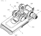
- FIGS. 1 to 25 illustrate a rehabilitation exercise device 1 for upper and lower limbs according to an embodiment of the present disclosure.
- the rehabilitation exercise device 1 includes a rehabilitation exercise unit 3 and a holder 5 for supporting the rehabilitation exercise unit 3.
- the rehabilitation exercise unit 3 includes: a first support 310 for supporting a user's hand or foot; a second support 320 for supporting a user's forearm or calf; a pair of first hinges 311 and 312 for rotatably connecting the first support 310 and the second support 320 to each other; a third support 330 for supporting a user's upper arm or thigh; and a pair of second hinges 331 and 332 for rotatably connecting the second support 320 and the third support 330 to each other.
- the holder 5 includes a base plate 510, and a mounting plate 520 on which the rehabilitation exercise unit 3 is mounted.
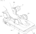
- the base plate 510 and the mounting plate 520 adopt a link-mechanism that converts horizontal motion into vertical motion.
- the link-mechanism is such that a first side of the mounting plate 520 is installed on the base plate 510 to be horizontally movable along a plate surface thereof, an intermediate region of the mounting plate 520 is connected to a first side of a link member 530, and a second side of the link member 530 is rotatably installed on the base plate 510.
- FIG. 1 in a state in which the mounting plate 520 is folded to the base plate 510, as illustrated in FIG. 3 , upper limb rehabilitation exercise is performed.
- FIG. 2 in a state in which the mounting plate 520 is erected at a certain angle from the base plate 510 by the link mechanism, as illustrated in FIG. 4 , lower limb rehabilitation exercise is performed.
- angle adjustment between the mounting plate 520 and the base plate 510, and angle fixing and releasing will be described later.
- the rehabilitation exercise unit 3 includes a distance adjustment part for adjusting the distance between the first support 310 and the third support 330 by adjusting the length of the second support 320 according to application in an upper or lower limb, and the length of a rehabilitation patient's upper or lower limb.
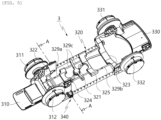
- the distance adjustment part of the rehabilitation exercise unit 3 according to the present disclosure will be described with reference to FIGS. 5 to 8 .
- the rehabilitation exercise unit 3 adopts a stacked slide-crank structure to the second support 320 so that the length of the second support 320 supporting the forearm or the calf is adjusted.
- the second support 320 may include a first fixing plate 322, a second fixing plate 323, a first moving plate 324, a second moving plate 325, and a hinge shaft 321.
- the first fixing plate 322 is connected to the pair of first hinges 311 and 312 to be rotatably coupled to the first support 310.
- the second fixing plate 323 is connected to the pair of second hinges 331 and 332 to be rotatably coupled to the third support 330.
- the first moving plate 324 is provided between the first fixing plate 322 and the hinge shaft 321 and is movable reciprocally therebetween.
- the second moving plate 325 is provided between the second fixing plate 323 and the hinge shaft 321 and is movable reciprocally therebetween.
- the hinge shaft 321 is provided between the first fixing plate 322 and the second fixing plate 323.
- the distance adjustment part includes a first crank 326 and a second crank 327.
- the first crank 326 is rotatably connected to the first fixing plate 322 and the hinge shaft 321 to convert a rotary motion of the hinge shaft 321 into a linear motion of the first fixing plate 322.
- the first crank 326 includes a first adjustment link 326a, a second adjustment link 326b, and a first connection link 326c.
- the first adjustment link 326a is rotatably coupled to the hinge shaft 321.
- the second adjustment link 326b has a first side rotatably coupled to the first adjustment link 326a, and a second side rotatably coupled to the first fixing plate 322.
- the first connection link 326c is rotatably coupled to the first moving plate 324 and an intermediate region of the first adjustment link 326a.
- the second crank 327 is rotatably connected to the second fixing plate 323 and the hinge shaft 321 to convert a rotary motion of the hinge shaft 321 into a linear motion of the second fixing plate 323.
- the second crank 327 includes a third adjustment link 327a, a fourth adjustment link 327b, and a second connection link 327c.
- the third adjustment link 327a is rotatably coupled to the hinge shaft 321.
- the third adjustment link 327a is disposed opposite to the first adjustment link 326a at an angle of 180 degrees.
- the fourth adjustment link 327b has a first side rotatably coupled to the third adjustment link 327a, and a second side rotatably coupled to the second fixing plate 323.
- the fourth adjustment link 327b is disposed opposite to the second adjustment link 326b.
- the second connection link 327c is rotatably coupled to the second moving plate 325 and an intermediate region of the third adjustment link 327a.
- the second connection link 327c is disposed opposite to the first connection link 326c.
- first guide rods 329a reciprocating movement of the first moving plate 324 is guided by a pair of first guide rods 329a extending in length from the first fixing plate 322 toward the first moving plate 324.
- reciprocating movement of the first moving plate 324 is guided by a pair of third guide rods 329c extending in length from the hinge shaft 321 toward the first moving plate 324.
- first guide rods 329a and the third guide rods 329c are provided in pairs, respectively, but the present disclosure is not limited thereto.
- at least one first guide rod 329a and at least one third guide rod 329c may be provided.
- reciprocating movement of the second moving plate 325 is guided by a pair of second guide rods 329b extending in length from the second fixing plate 323 toward the second moving plate 325.
- reciprocating movement of the second moving plate 325 is guided by a pair of third guide rods 329c extending in length from the hinge shaft 321 toward the second moving plate 325.
- the second guide rods 329b and the third guide rods 329c are provided in pairs, respectively, but the present disclosure is not limited thereto.
- at least one second guide rod 329b and at least one third guide rod 329c may be provided.
- the slide-crank mechanism in which the first fixing plate 322 and the first moving plate 324, and the second fixing plate 323 and the second moving plate 325 are operated in conjunction with each other, respectively, so as to be mutually approached or spaced apart with respect to the hinge shaft 321, it is possible to adjust the length of the second support 320, thereby adjusting the distance between the first support 310 and the third support 330.
- the first fixing plate 322 and the first moving plate 324, and the second fixing plate 323 and the second moving plate 325 are operated in conjunction with each other, respectively, so as to be mutually approached or spaced apart with respect to the hinge shaft 321.
- first fixing plate 322 and the second fixing plate 323 are connected to each other by a pair of connection bars 328.
- connection bars 328 a side of each of the connection bars 328 is fixed to the second fixing plate 323, and the first fixing plate 322 is movably coupled to the connection bars 328, so that the first fixing plate 322 is approached to and spaced apart from the second fixing plate 323.
- a through-hole 322a (see FIG. 8 ) for allowing passage of each of the connection bars 328 therethrough may be formed in the first fixing plate 322, so that longitudinal movement of the first fixing plate 322 may be guided along the connection bar 238.
- a length stopper 340 may be installed on the first fixing plate 322 to restrain the longitudinal movement of the first fixing plate 322, for example, to limit relative movement of the first fixing plate 322 and the second fixing plate 323.
- a pair of length stoppers 340 are installed on the pair of connection bars 328, respectively.
- FIG. 8 is a sectional view illustrating the region of the length stopper 340 according to the present disclosure.
- the length stopper 340 may include a restraining lever 341 and a pressurizing member 345.
- the restraining lever 341 is rotatably installed on a rotary shaft 322b coupled to the first fixing plate 322.
- the restraining lever 341 includes a pusher 342 provided at a first end thereof to pressurize or release the pressurizing member 345, and a knob 343 provided at a second end thereof to rotate the pusher 342 to allow the pusher 342 to pressurize or release the pressurizing member 345.
- the pusher 342 has a semicircular arc shape having a predetermined radius of curvature, and is configured to be brought into contact with and spaced apart from the pressurizing member 345 by rotation.
- connection bar 238 is allowed to be moved inside the through-hole 322a, thereby allowing the movement of the first fixing plate 322 in the longitudinal direction along the connection bar 328.
- connection bar 328 is fixed to the second fixing plate 323, and the first fixing plate 322 is movably coupled to the connection bar 328, but the present disclosure is not limited thereto.
- the side of the connection bar 328 may be fixed to the first fixing plate 322, and the second fixing plate 323 may be movably coupled to the connection bar 328.
- the restraining lever 341 is provided on the second fixing plate 323.
- FIGS. 9 to 12 are views illustrating an example of a structure for restraining longitudinal movement of a second support 320 according to another embodiment of the present disclosure.
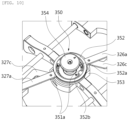
- a rehabilitation exercise unit 3 may include a rotation stopper 350 provided on a hinge shaft 321 to limit relative movement of a first fixing plate 322 and a second fixing plate 323.
- the second support 320 has a slide-crank structure in adjusting a longitudinal length thereof, which includes rotation of the hinge shaft 321.
- the rotation stopper 350 restrains the rotation of the hinge shaft 321 to maintain a predetermined length.
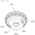
- the rotation stopper 350 includes a restraining dial 351, a shaft body 353 for forming the hinge shaft 321, a shaft column 354 protruding upward from the shaft body 353, and a shaft plate 352 rotated around the shaft body 354 and connected to the first adjustment link 326a and the third adjustment link 327a to rotate the first adjustment link 326a and the third adjustment link 327a with respect to the shaft body 353.
- the restraining dial 351 includes a restraining pin 351a and a catching recess 351c.
- the restraining pin 351c is formed by protruding from an end of the restraining dial 351 oriented toward the shaft body 353, and is inserted into or released from any one selected from among a plurality of restraining holes 352a which will be described later.
- the catching recess 351c is depressed in a region of the end of the restraining dial 351 oriented toward the shaft body 353, at a position spaced from the restraining pin 351a.
- a pair of catching recesses 351c are provided opposite to each other.
- the plurality of restraining holes 352a are formed in the shaft body 353 at a predetermined interval along the circumferential direction of the shaft column 354.
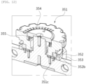
- the shaft plate 352 has a circular ring shape.
- the shaft plate 352 is configured such that the first adjustment link 326a and the third adjustment link 327a are connected to an outer circumference thereof, and the restraining dial 351 is rotatably provided on an inner circumference thereof.
- the shaft plate 352 has a pair of catching protrusions 352b protruding from a region of the inner circumference thereof, and connecting the restraining dial 351 to the shaft plate 352 by being caught by the catching recesses 351c of the restraining dial 351.
- rotation stopper 350 may further include an elastic member 355.
- the elastic member 355 is provided between the shaft column 354 and the restraining dial 351, and generates elastic force acting on the restraining dial 351 so that the restraining pin 351a is inserted into the selected restraining hole 352a.
- the user adjusts the length by pulling the restraining dial 351 upward so that the restraining dial 351 ascends from the shaft body 353 to a position where the restraining pin 351a is separated from the restraining hole 352a. Then, when the second support 320 is adjusted to a desired length, the user releases the restraining dial 351 so that the restraining dial 351 descends toward the shaft body 353 by the elastic force of the elastic member 355, and at the same time, the restraining pin 351a is inserted into the restraining hole 352a at a corresponding position.
- the shaft plate 352 when the restraining pin 351a is inserted into the restraining hole 352a, the shaft plate 352 is not rotated with respect to the shaft body 353, so that the length of the second support 320 is not allowed to be adjusted.
- the catching protrusions 352b of the shaft plate 352 are caught by the catching recesses 351c of the restraining dial 351, so that the restraining dial 351 is prevented from being rotated around the shaft column 354.
- the shaft plate 352 is rotated with respect to the shaft body 353, so that the length of the second support 320 is allowed to be adjusted.
- the catching protrusions 352b of the shaft plate 352 are maintained caught by the catching recesses 351c of the restraining dial 351, so that the restraining dial 351 is maintained in a state connected to the shaft plate 352.
- the restraining dial 351 is allowed to be rotatable forward and backward around the shaft column 354, so that the first fixing plate 322 and the second fixing plate 323 are mutually approached or spaced apart with respect to the shaft body 353, thereby adjusting the length of the second support 320.
- reference numeral 351b denotes a pin insertion portion into which the restraining pin 351a is inserted and fixed
- reference numeral 351d denotes a shaft through-hole through which the shaft column 354 passes and fixed.
- FIG. 10 illustrates a state in which the restraining pin 351a is inserted in the restraining hole 352a in a state of being released from the restraining dial 351.
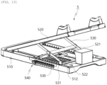
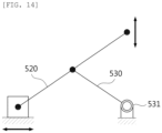
- the holder 5 may include the base plate 510, the mounting plate 520, and the link member 530. According to this configuration, a link mechanism as illustrated in FIG. 14 is implemented.
- the opposite sides of the link member 530 are rotatably coupled to the base plate 510 and the mounting plate 520, respectively.
- the first side (i.e., in the direction of the first support 510) of the mounting plate 520 is coupled to the base plate 510 to be horizontally movable along the plate surface thereof, and the first side of the link member 530 is rotatably coupled to the intermediate region of the mounting plate 520.
- a second side of the mounting plate 520 is approached to and spaced apart from the base plate 510 in the vertical direction by the link mechanism, so that angle adjustment is implemented as illustrated in FIGS. 1 and 2 .
- the second side of the link member 530 is rotatably coupled to a fixing shaft 531 provided on the base plate 510, so that when the first side of the mounting plate 520 moves in the horizontal direction, the angle of the mounting plate 520 is adjusted by rotation of the opposite sides of the link member 530.
- a pair of extension brackets 521 are installed opposite at the first side of the mounting plate 520 by extending parallel toward the third support 330.
- First ends of the pair of extension brackets 521 for example, first ends thereof oriented toward the first support 310, are rotatably coupled to the mounting plate 520.
- Second ends of the pair of extension brackets 521 for example, second ends thereof oriented toward the third support 330, are connected to each other by a connection rod 522.
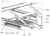
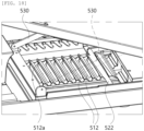
- a catching plate 511 is installed inside the base plate 510, with a plurality of catching protrusions 512 formed thereon along the longitudinal direction and allowing the connection rod 522 to be caught thereby in response to the angle between the mounting plate 520 and the base plate 510.
- the plurality of catching protrusions 512 are formed at a predetermined interval along the longitudinal direction of the pair of extension brackets 521, so that the connection rod 522 is selectively caught by the catching protrusions 512.
- the connection rod 522 is caught by any one of the catching protrusions 512, so that the inclination angle is maintained at a predetermined angle.
- the holder 5 may include a fixing unit 540 for fixing the connection rod 522 to maintain the connection rod 522 caught by any one of the catching protrusions 512.
- the base plate 510 includes a plurality of restraining recesses 513a and a moving hole 513b.
- the plurality of restraining recesses 513a are depressed in a side surface of the base plate 510 at respective positions corresponding to the catching protrusions 512.
- the plurality of restraining recesses 513a are arranged at a predetermined interval on the side surface of the base plate 510 along the longitudinal direction thereof in correspondence with the catching protrusions 512 arranged along the longitudinal direction of the extension brackets 521.
- the moving hole 513b is formed in each of the restraining recesses 513a by passing therethrough to be oriented toward a selected catching protrusion 512.
- the moving hole 513b is formed to pass through an inside and an outside of a plate surface of the base plate 510 at a position where the restraining recess 513a is formed.
- the moving hole 513b has a shape that is open diagonally upward to allow insertion or release of an extension unit 542 of a fixing unit 540, which will be described later, into or from the moving hole 513b.
- the fixing unit 540 may include the extension unit 542 and a unit body 541.
- the extension unit 542 has a first side connected to the connection rod 522, and a second side extending outward of the base plate 510 through the moving hole 513b.
- the first side of the extension unit 542 is connected to the connection rod 522 through an intermediate plate 543.
- the intermediate plate 543 may be directly fastened to the connection rod 522 or may be connected to the connection rod 522 by being fastened to an associated one of the extension brackets 521 connected to the connection rod 522.
- the unit body 541 is coupled to the second side of the extension unit 542.
- an insertion hole (not illustrated) for allowing insertion of the extension unit 542 therein is formed in the unit body 541 so that the extension unit 542 is inserted into the insertion hole to be coupled to the unit body 541.
- the unit body 541 is coupled to the extension unit 542 so as to be movable between a fixing position inserted into the restraining recess 513a and a release position released from the restraining recess 513a.
- the extension unit 542 has a pair of operating grooves 542b formed at a predetermined interval along the longitudinal direction thereof.
- the unit body 541 has an operating protrusion 541c caught by the operating grooves 542b at the fixing position and the release position of the unit body 541, respectively.
- the operating protrusion 541c may be configured in a form that is elastically pressurized in the directions of the operating grooves 542b so that when the user pulls the unit body 541 in the release direction, the operating protrusion 541c caught by an inner operating groove 542b is released therefrom and inserted into an outer operating groove 542b.
- the operating protrusion 541c caught by the outer operating groove 542b is released therefrom and inserted into the inner operating groove 542b.
- the unit body 541 includes an insertion portion 541b inserted into the restraining recess 513a at the fixing position and the release position, and a knob 541a operable by the user to move the unit body 541 between the fixing position and the release position.
- the insertion portion 541b is configured in a size that is insertable into the restraining recess 513a, preferably in a size that is caught by the moving hole 513b without moving thereinto.
- the user when the user wants to adjust the angle between the base plate 510 and the mounting plate 520, the user pulls the knob 541a with the unit body 541 being at the fixing position to allow the unit body 541 to be moved to the release position, so that the insertion portion 541b of the unit body 541 is released from the restraining recess 513a.
- the user pushes back the unit body 541 to allow the insertion portion 541b to be inserted into a restraining recess 513a associated with the moving hole 513b. Then, the insertion portion 541b is caught by the moving hole 513b, so that the connection rod 522 is fixed to the selected catching protrusion 512.
- each of the catching protrusions 512 may extend to a length corresponding to the length of the connection rod 522 in a direction intersecting the longitudinal direction of the extension brackets 521, i.e., in the longitudinal direction of the connection rod 522.
- each of the catching protrusions 512 may be configured such that a side thereof in a direction in which the fixing unit 540 is installed, i.e., a D1 direction in FIG. 19 , protrudes relatively more than an opposite side thereof in a D2 direction, in a direction in which catching is released.
- the fixing unit 540 is installed only on a side of the base plate 510.
- a lengthwise side of the connection rod 522 in the direction of the fixing unit 540 may be lifted relatively more in the release direction, and an opposite lengthwise side may be lifted relatively less.
- the rehabilitation exercise device 1 for the upper and lower limbs may further include an elastic unit 522f.
- the elastic unit 522f provides an elastic force acting in a direction in which the connection rod 522 is maintained caught by the catching protrusion 512, so that the connection rod 522 is prevented from being released from the catching protrusion 512 without a user's manipulation.
- the unit body 541 of the fixing unit 540 is located at the release position due to a process of a user's manipulation or other cause
- the connection rod 522 is released from the catching protrusion 512 due to an external impact or the like
- the mounting plate 520 may be rapidly folded in the direction of the base plate 510. Therefore, the release of the connection rod 522 is prevented even with a certain impact, so that a safety accident is prevented from occurring.
- connection rod 522 is in a state of being pressurized in the insertion direction into the catching protrusion 512. Therefore, a force that moves the connection rod 522 in the insertion direction is generated at an insertion position of the connection rod 522, thereby facilitating the insertion of the connection rod 522 into the catching protrusion 512.
- the mounting plate 520 may include a moving bracket 526, a pair of mounting brackets 525, and a mounting portion 527.
- the moving bracket 526 is installed on the base plate 510 to be horizontally movable along the base plate 510.
- the pair of mounting brackets 525 are rotatably coupled to opposite sides of the moving bracket 526.
- each of the pair of link members 530 may be rotatably coupled to an intermediate region of an associated one of the mounting brackets 525.
- the mounting portion 527 is formed in a plate shape supported by the moving bracket 526 and the mounting brackets 525 to define an upper plate of the mounting plate 520, and allows mounting of the rehabilitation exercise unit 2 thereon.
- extension brackets 521 are rotatably coupled to the opposite sides of the moving brackets 526 so that the moving bracket 526 is moved in conjunction with movement of the extension brackets 521.
- the elastic unit 522f pressurize at least one of the pair of extension brackets 521 downward in a state of being installed on the moving bracket 526, so that the connection rod 522 coupled to the extension brackets 521 is pressurized in a direction caught by the catching protrusion 512.
- the elastic unit 522f is provided in the form of a plate spring.
- the extension bracket 521 has a skirt 522d extending inward, so that the elastic unit 522f pressurizes the skirt 522d to pressurize the extension bracket 521.
- the drive module 7 may be selectively couple to any one of the pair of first hinges 311 and 312 and the pair of second hinges 331 and 332.
- the drive module 7 in the case of the upper limb, when the drive module 7 is mounted on any one of the first hinges 311 and 312, wrist rehabilitation exercise is possible.
- the drive module 7 is mounted on any one of the second hinges 331 and 332, elbow joint rehabilitation exercise is possible.
- a mounting position of the drive module 7 may be determined according to rehabilitation of a left or right upper limb.
- the drive module 7 may be selectively mounted according to rehabilitation of a right or left upper limb.
- the drive module 7 is selectively mounted on any one of the pair of first hinges 311 and 312 and the pair of second hinges 331 and 332 to pivot the first support 310 or the second support 320.
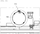
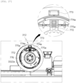
- the drive module 7 may include a body housing 710 in which components such as a drive motor, a printed circuit board, etc. are accommodated, a drive shaft 720 to which a rotary shaft of the drive motor is connected, and a ring member 730 for allowing mounting and fixing of the drive module 7 on the first hinges 311 and 312 or the second hinges 331 and 332.
- a ring coupling portion 751 is formed on each of the first hinges 311 and 312 or each of the second hinges 331 and 332.
- the drive module 7 is mounted on the second hinge 332 located on the right side as viewed from the first support 310 to the third support 330 in FIG. 1 . Therefore, for convenience of explanation, the second hinge 332 located on the right side is hereinafter referred to as a right second hinge 332.
- a plurality of mounting protrusions 731 are formed on an inside of the ring member 730 at a predetermined interval along the circumferential direction of the ring member 730, and a ring coupling portion 751 to which the ring member 730 of the drive module 7 is coupled is provided circumferentially around an opening of the right second hinge 332.
- a plurality of catching portions 753 may be formed in the ring coupling portion 751 corresponding to the mounting protrusions 731.
- a catching lever 740 is provided on the body housing 710a to restrain rotation of the ring member 730 by being inserted into the ring member 730, so that after rotating the ring member 730, the catching lever 740 is pushed and inserted into the ring member 730 to thereby prevent rotation of the ring member 730.
- the right second hinge 332 may have a rotary shaft hole 3322a for receiving the drive shaft of the drive module 7.
- the drive shaft 720 of the drive module 7 passes through the rotary shaft hole 3322a and is coupled to the right second hinge 332 when the drive module 7 is mounted on the right second hinge 332.
- the second support 320 is pivoted.
- the second support 320 includes a shaft coupling bracket 3231 and a drive shaft fixing member 360.
- the shaft coupling bracket 3231 may extend toward the drive shaft of the drive module 7. In the embodiment of the present disclosure, as an example, as illustrated in FIG. 21 , the shaft coupling bracket 3231 extends from the second fixing plate 323 of the second support 320 toward the rotary shaft of the drive motor.
- the drive shaft fixing member 360 fixes the drive shaft 720 inserted through the rotary shaft hole 3322a to the shaft coupling bracket 3231 when the drive module 7 is fastened to the right second hinge 332.
- the shaft coupling bracket 3231 is pivoted in response to the rotation of the drive shaft 720, so that the entire second support 320 is pivoted with respect to the third support 330.
- the drive shaft 720 has a polygonal shape in cross-section.
- FIGS. 21 and 23 illustrate that the drive shaft 720 has a hexagonal shape in cross-section, the scope of the present disclosure is not limited thereto.
- the drive shaft fixing member 360 may include a polygonal fixing hole 364 having a polygonal inner diameter.
- the polygonal fixing hole 364 may also be configured to have a hexagonal inner diameter corresponding to the drive shaft 720 having a hexagonal shape in cross-section.
- the drive shaft fixing member 360 may include a bracket fastening portion 361 and a pair of tightening members 362 and 363.
- the bracket fastening portion 361 is provided at a first side of the drive shaft fixing member 360 with respect to the polygonal fixing hole 364, and is fastened to the shaft coupling bracket 3231 to fix the drive shaft fixing member 360 to the shaft coupling bracket 3231.
- the pair of tightening members 362 and 363 are provided at a second side of the drive shaft fixing member 360 with respect to the polygonal fixing hole 364, and are spaced apart from each other with a space 365 formed therebetween. As illustrated in FIG. 22 , the fixing hole 364 is formed between the pair of tightening members 362 and 363. In a state in which the drive shaft 720 is inserted into the polygonal fixing hole 364, the pair of tightening members 362 and 363 are approached to each other, so that the drive shaft 720 inserted into the polygonal fixing hole 364 is tightened and fixed.
- the pair of tightening members 362 and 363 are branched from the bracket fastening portion 361, but the present disclosure is not limited thereto.
- the pair of tightening members 362 and 363 may be configured such that two symmetrical members are combined at respective first sides thereof to form the bracket fastening portion 361, with respective second sides thereof spaced apart from each other.
- the bracket fastening portion 361 is fastened to the shaft coupling bracket 3231 through bolt fastening.
- a plurality of bolt fastening holes 366c and 366d are formed in the bracket fastening portion 361, and in the present disclosure, as an example, the bolt fastening is performed in the biaxial direction.
- the plurality of bolt fastening holes 366c and 366da include a pair of bolt fastening holes 366c fastened to coupling holes 3231a formed in a plate surface of the shaft coupling bracket 3231, and a pair of bolt fastening holes 366b fastened to coupling holes 3234a formed in a pair of extension portions 3234 extending in a U-shape from the plate surface of the shaft coupling bracket 3231.
- any one of the pair of tightening members 362 and 363 may have a first tightening hole 366a passing through a side thereof, and a remaining one of the pair of tightening members 362 and 363 may have a second tightening hole (not illustrated) for fastening a tightening bolt (not illustrated) passing through the first tightening hole so as to adjust the distance between the tightening members 362 and 363.
- the right second hinge 332 may include a first rotary part 3322 and a second rotary part 3321.
- the first rotary part 3322 is rotated in conjunction with the right second support 320 in response to rotation of the drive shaft 720.
- the second rotary part 3321 is installed to be freely rotatable with respect to the first rotary part 3322, and is connected to the third support 330 to be rotated in conjunction with the third support 330.
- the first rotary part 3322 and the second rotary part 3321 are coaxially coupled around the rotary shaft hole 3322a.
- the first rotary part 3322 is axially coupled to the shaft coupling bracket 3231 to be rotated relative to the second rotary part 3321 in conjunction with rotation of the drive shaft 720.
- FIG. 23 is a view illustrating a state in which the drive shaft fixing member 360 is removed
- FIG. 24 is a view illustrating a state in which the shaft coupling bracket 3231 is removed.
- the shaft coupling bracket 3231 may further include a bracket coupling hole 3232 and a plurality of rotation synchronization holes 3233.
- the bracket coupling hole 3322 is formed corresponding to the rotary shaft hole 3322a, and allows passage of the drive shaft 720 passing through the rotary shaft hole 3322a.
- the drive shaft 720 passing through the bracket coupling hole 3232 is fixed by the drive shaft fixing member 360.
- the rotation synchronization holes 3233 are formed by passing through the plate surface of the shaft coupling bracket 3231 along the outer periphery of the bracket coupling hole 3232.
- the first rotary part 3322 may include a plurality of rotation synchronization protrusions 3322b.
- the rotation synchronization protrusions 3322b are inserted into the respective rotation synchronization holes 3233, so that when the drive shaft 720 is rotated in response to the driving of the drive module 7, the first rotary part 3322 is rotatable in conjunction with rotation of the shaft coupling bracket 3231.
- the configuration of the right second hinge 332 driven by being coupled to the drive module 7 described with reference to FIGS. 21 to 24 is symmetrically implemented in the remaining second hinge 331.
- the same mechanism may be applied to each of the first hinges 311 and 312, except that the first support 310 and the second support 320 are configured such that the first support 310 is pivoted in response to the driving of the drive module 7.
- a hinge cover may be installed where the drive module 7 is not installed from among the pair of first hinges 311 and 312 and the pair of second hinges 331 and 332.
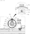
- FIGS. 25 to 28 illustrate the first hinge 312 on the right side from among the first hinges 311 and 312.
- the rotation restraining part 770 includes a rotary gear plate 776 rotated in conjunction with the first rotary part 3322, i.e., the first rotary part 3322 rotated in conjunction with the first support 310 or the second support 320, and a gear restraining member 771 installed on the second rotary part 3321.
- the rotary gear plate 776 may have gear teeth circumferentially formed along an end thereof, and the gear restraining member 771 may have a gear insertion portion 772 formed at an end thereof to be insertable into a space between the gear teeth.
- the gear insertion portion 772 is inserted into the space between the gear teeth of the rotary gear plate 776 by sliding the gear restraining member 771, rotation of the first rotary part 3322 is restrained.
- the rotation restraining part 770 may include a pair of restraining protrusions 774 protruding opposite to each other and being able to be elastically pressurized.
- a pair of restraining recesses 775 may be formed in a plate surface of the second rotary part 3321 at each side of the rotation restraining part 770 along the moving direction of the rotation restraining part 770 so that when the rotation restraining part 770 is moved in the vertical direction, the restraining protrusions 774 are inserted into the restraining recesses 775.
- the second support 320 performs a pivoting motion by a rotational force of the drive module 7, whereas the first support 310 is limited in pivoting motion, so that the user can exercise an elbow joint while a wrist joint is not moved.
- the first support 310 performs a pivoting motion by the rotational force of the drive module 7, whereas the second support 320 is limited in pivoting motion, so that the user can exercise the wrist joint while the elbow joint is not moved.
- the above configuration may be applied equally to the second hinges 331 and 332.
- FIG. 26 is a view illustrating the configuration of a rotation restraining part 770 according to another embodiment of the present disclosure.
- a pair of restraining recesses 774a are formed on each side of the rotation restraining part 270, and a restraining rod 775a installed in the second rotary part 3321 is inserted into the restraining recesses 774a.
- the restraining rod 775a is elastically pressurized in a direction of being inserted into the restraining recesses 774a, and, for example, may have a configuration that is pressurized in the direction of being inserted into the restraining recesses 774a by an elastic force of a spring.
- the drive module 7 may include a gear protrusion.
- the gear protrusion is installed on a position capable of being in contact with the gear restraining member 771 at a position where the gear restraining member 771 is meshed with the rotary gear plate 776.
- the drive module 7 is prevented from being fastened to the first hinges 311 and 312 or the second hinges 331 or 332 in a state in which the gear restraining member 771 is meshed with the rotary gear plate 776, i.e., in a state in which the first rotary part 3322 and the second rotary part 3321 cannot be rotated relative to each other.
- each of the first hinges 311 and 312 and the second hinges 331 and 332 may have a status display window 773 on which a current status is displayed in response to the operation of the gear restraining member 771.
- 'Lock' may be displayed on the status display window 773.
- 'Unlock' may be displayed on the status display window 773.
- this may be mechanically implemented so that such characters are displayed in conjunction with sliding movement of the gear restraining member 771.
- the gear restraining member 771 is installed on the second rotary part 3321 and the rotary gear plate 776 is configured to be rotated in conjunction with the first rotary part 3322.
- the opposite example may be applied.
- the gear restraining member 771 may be installed on the first rotary part 3322, and the rotary gear plate 776 may be configured to be rotated in conjunction with the second rotary part 3321.
- the rehabilitation exercise apparatus 1 may enable the user to perform rehabilitation by selectively mounting the drive module 7 to each hinge in response to a position of the upper or lower limb to be exercised.
- the rehabilitation exercise device 1 when the drive module 7 is mounted on the left second hinge 311 or the left second hinge 331, the rehabilitation exercise device 1 according to the embodiment of the present disclosure is worn on a right upper limb to exercise, without causing interference of the drive module 7 with a user's torso.
- the drive module 7 when the drive module 7 is mounted on the left first hinge 311, exercise of a right wrist joint is possible.
- exercise of a right elbow joint is possible.
- the rehabilitation exercise device 1 When the drive module 7 is mounted on the right second hinge 312 or the left second hinge 332, the rehabilitation exercise device 1 according to the embodiment of the present disclosure is worn on a left upper limb to exercise, without causing interference of the drive module 7 with the user's torso.
- the drive module 7 when the drive module 7 is mounted on the right first hinge 312, exercise of a left wrist joint is possible.
- the drive module 7 is mounted on the right second hinge 332, exercise of a left elbow joint is possible.
- the drive module 7 may be configured to enable interworking with an app installed in a smart device such as a smart phone.
- a smart device such as a smart phone.
- the rehabilitation exercise apparatus 1 may include a mounting position detecting part for automatically detecting the mounting position of the drive module 7.
- the mounting position detecting part detects the mounting position where the drive module 7 is mounted from among the pair of first hinges 311 and 312 and the pair of second hinges 331 and 332.
- the mounting position detecting part includes a to-be-detected module, and a sensor module HS.
- the to-be-detected module is installed on each of the pair of first hinges 311 and 312 and the pair of second hinges 331 and 332.
- the sensor module HS is installed in the drive module 7, and recognizes the to-be-detected module when the drive module 7 is mounted on any one of the first hinges 311 and 312 and the second hinges 331 and 332.
- the respective to-be-detected modules installed on the first hinges 311 and 312 and the second hinges 331 and 332 are configured to be distinguishably recognized, so that the sensor module HS recognizes where the drive module 7 is installed from among the first hinges 311 and 312 and the second hinges 331 and 332.
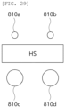
- FIGS. 28 and 29 are views illustrating an example of the configuration of a mounting position detecting part according to an embodiment of the present disclosure.
- the sensor module HS according to the embodiment of the present disclosure includes a Hall sensor.
- the Hall sensor is installed in the body housing 710 of the drive module 7.
- the respective to-be-detected modules include magnet members M and magnet holes 810a, 810b, 810c, and 810d.
- the respective magnet members M may be embedded in the first hinges 331 and the second hinges 331 and 332 at positions corresponding to each other.
- the magnet members M are installed at positions detectable by the Hall sensor when the drive module 7 is mounted on the first hinges 311 and 312 or the second hinges 331 and 332.
- the magnet holes 810a, 810b, 810c, and 810d are formed in the first hinges 311 and 312 and the second hinges 331 and 332, respectively, to allow exposure of the magnet members M therethrough.
- the respective magnet holes 810a, 810b, 810c, and 810d may be configured to differ in at least one of position and size, so that when detecting the magnetic fields of the magnet members M, the Hall sensor recognizes the mounting position of the drive module 7 by detecting magnetic fields having different characteristics according to the positions and sizes of the magnet holes 810a, 810b, 810c, and 810d.
- the four magnet holes 810a, 810b, 810c, and 810d formed in the first hinges 311 and 312 and the second hinges 331 and 332, respectively, may be located at upper and lower positions with respect to the Hall sensor.
- the magnet hole 810a is formed in the right first hinge 312
- the magnet hole 810b is formed in the left first hinge 311
- the magnet hole 810c is formed in the right second hinge 332
- the magnet hole 810d is formed in the left second hinge 331
- the mounting position of the drive module 7 is recognized by detecting magnetic fields having different characteristics according to the positions of the magnet holes 810a, 810b, 810c, and 810d.
- magnet holes 810a, 810b, 810c, and 810d have different positions and sizes, other configurations are possible as long as magnetic field characteristics are distinguishable.
- the to-be-detected module may include a short-range communication tag, for example, a RF or NFC tag, in which information on a corresponding position is embedded, and the sensor module HS may include a reader that recognizes the information embedded in the tag.
- a short-range communication tag for example, a RF or NFC tag
- the sensor module HS may include a reader that recognizes the information embedded in the tag.
- the present disclosure can find application in a rehabilitation exercise device for rehabilitation of a patient's upper or lower limb.
Landscapes
- Health & Medical Sciences (AREA)
- Epidemiology (AREA)
- Pain & Pain Management (AREA)
- Physical Education & Sports Medicine (AREA)
- Rehabilitation Therapy (AREA)
- Life Sciences & Earth Sciences (AREA)
- Animal Behavior & Ethology (AREA)
- General Health & Medical Sciences (AREA)
- Public Health (AREA)
- Veterinary Medicine (AREA)
- Rehabilitation Tools (AREA)
Claims (1)
- Rehabilitationsübungsgerät (1) für obere und untere Gliedmaßen, wobei das Rehabilitationsübungsgerät umfasst:eine erste Stütze (310), die die Hand oder den Fuß eines Benutzers stützt;eine zweite Stütze (320), die den Unterarm oder die Wade eines Benutzers stützt;ein Paar erster Scharniere (311, 312), die die erste Stütze (310) und die zweite Stütze (320) drehbar miteinander verbinden;eine dritte Stütze (330), die den Oberarm oder Oberschenkel eines Benutzers stützt;ein Paar zweiter Scharniere (331), die die zweite Stütze (320) und die dritte Stütze (330) drehbar miteinander verbinden; undein Antriebsmodul, das selektiv an einem beliebigen der beiden ersten Gelenke (311, 312) und der beiden zweiten Gelenke (331) angebracht ist und so konfiguriert ist, dass es die erste Stütze (310) oder die zweite Stütze (320) schwenkt,wobei jedes der ersten Gelenke (311, 312) oder jedes der zweiten Gelenke (331) Folgendes umfasst:ein erstes Drehteil (3322), das mit dem ersten Träger (310) oder dem zweiten Träger (320) verbunden ist und so konfiguriert ist, dass es in Verbindung mit dem Antrieb des Antriebsmoduls gedreht wird; undein zweites Drehteil (3321), das mit dem zweiten Träger (320) oder dem dritten Träger (330) verbunden ist und so konfiguriert ist, dass es relativ zu dem ersten Drehteil (3322) gedreht wird, undein Drehbegrenzungsteil (770) ist ferner vorgesehen, wobei das Drehbegrenzungsteil (770) an dem ersten Scharnier (311, 312) oder dem zweiten Scharnier angebracht ist und so konfiguriert ist, dass es eine relative Drehung zwischen dem ersten Drehteil (3322) und dem zweiten Drehteil (3321) begrenzt (1), wobei das Drehbegrenzungsteil (770) umfasst:eine Drehzahnradplatte (776), die mit dem ersten Drehteil (3322) oder dem zweiten Drehteil (3321) verbunden ist, um zusammen mit dem ersten Drehteil (3322) oder dem zweiten Drehteil (3321) gedreht zu werden, und die entlang eines Endes davon in Umfangsrichtung ausgebildete Zahnradzähne aufweist; undein Zahnrad-Rückhalteelement (771), das an dem verbleibenden ersten Drehteil (3322) oder zweiten Drehteil (3321) angebracht ist und so konfiguriert ist, dass es die Drehung des ersten Drehteils (3322) oder des zweiten Drehteils (3321) durch Einfügen in einen Raum zwischen den Zähnen der Drehzahnradplatte (776) eingesetzt wird, wobei das Zahnrad-Rückhalteelement (771) an dem ersten Drehteil (3322) oder dem zweiten Drehteil (3321) so angebracht ist, dass es zwischen einer in den Raum zwischen den Zahnradzähnen eingesetzten Rückhalteposition und einer aus dem Raum freigegebenen Freigabeposition verschiebbar ist; undjedes der ersten Scharniere (311, 312) und der zweiten Scharniere (331) ferner ein Statusanzeigefenster umfasst, auf dem ein Betriebszustand des Drehhemmteils (270) (770) in Reaktion auf die Hemmposition und die Freigabeposition des Zahnradhemmelements (771) angezeigt wird, wobei das Antriebsmodul einen Zahnradvorsprung umfasst, der so konfiguriert ist, dass er die Montage des Antriebsmoduls verhindert, indem er vom Zahnrad-Rückhalteelement (771) erfasst wird, wenn das Antriebsmodul am ersten Scharnier (311, 312) oder am zweiten Scharnier in einem Zustand angebracht wird, in dem sich das Zahnrad-Rückhalteelement (771) in der Rückhalteposition befindet.
Applications Claiming Priority (5)
| Application Number | Priority Date | Filing Date | Title |
|---|---|---|---|
| KR1020190146775A KR102246049B1 (ko) | 2019-11-15 | 2019-11-15 | 상지 및 하지용 재활 운동 장치 |
| KR20200022970 | 2020-02-25 | ||
| KR1020200043958A KR102352604B1 (ko) | 2020-02-25 | 2020-04-10 | 상지 및 하지용 재활 운동 장치 |
| KR1020200141797A KR102469723B1 (ko) | 2020-10-29 | 2020-10-29 | 상지 및 하지용 재활 운동 장치 |
| PCT/KR2020/015126 WO2021096132A1 (ko) | 2019-11-15 | 2020-11-02 | 상지 및 하지용 재활 운동 장치 |
Publications (3)
| Publication Number | Publication Date |
|---|---|
| EP3984512A1 EP3984512A1 (de) | 2022-04-20 |
| EP3984512A4 EP3984512A4 (de) | 2023-08-02 |
| EP3984512B1 true EP3984512B1 (de) | 2025-01-08 |
Family
ID=75913081
Family Applications (1)
| Application Number | Title | Priority Date | Filing Date |
|---|---|---|---|
| EP20888275.3A Active EP3984512B1 (de) | 2019-11-15 | 2020-11-02 | Trainingsvorrichtung zur rehabilitation der oberen und unteren extremitäten |
Country Status (4)
| Country | Link |
|---|---|
| US (1) | US11992447B2 (de) |
| EP (1) | EP3984512B1 (de) |
| JP (1) | JP7198364B2 (de) |
| WO (1) | WO2021096132A1 (de) |
Families Citing this family (73)
| Publication number | Priority date | Publication date | Assignee | Title |
|---|---|---|---|---|
| US12029940B2 (en) | 2019-03-11 | 2024-07-09 | Rom Technologies, Inc. | Single sensor wearable device for monitoring joint extension and flexion |
| US11471729B2 (en) | 2019-03-11 | 2022-10-18 | Rom Technologies, Inc. | System, method and apparatus for a rehabilitation machine with a simulated flywheel |
| US11433276B2 (en) | 2019-05-10 | 2022-09-06 | Rehab2Fit Technologies, Inc. | Method and system for using artificial intelligence to independently adjust resistance of pedals based on leg strength |
| US11801423B2 (en) | 2019-05-10 | 2023-10-31 | Rehab2Fit Technologies, Inc. | Method and system for using artificial intelligence to interact with a user of an exercise device during an exercise session |
| US11957956B2 (en) | 2019-05-10 | 2024-04-16 | Rehab2Fit Technologies, Inc. | System, method and apparatus for rehabilitation and exercise |
| US12102878B2 (en) | 2019-05-10 | 2024-10-01 | Rehab2Fit Technologies, Inc. | Method and system for using artificial intelligence to determine a user's progress during interval training |
| US11904207B2 (en) | 2019-05-10 | 2024-02-20 | Rehab2Fit Technologies, Inc. | Method and system for using artificial intelligence to present a user interface representing a user's progress in various domains |
| US11957960B2 (en) | 2019-05-10 | 2024-04-16 | Rehab2Fit Technologies Inc. | Method and system for using artificial intelligence to adjust pedal resistance |
| US11833393B2 (en) | 2019-05-15 | 2023-12-05 | Rehab2Fit Technologies, Inc. | System and method for using an exercise machine to improve completion of an exercise |
| US11896540B2 (en) | 2019-06-24 | 2024-02-13 | Rehab2Fit Technologies, Inc. | Method and system for implementing an exercise protocol for osteogenesis and/or muscular hypertrophy |
| US12402804B2 (en) | 2019-09-17 | 2025-09-02 | Rom Technologies, Inc. | Wearable device for coupling to a user, and measuring and monitoring user activity |
| US11071597B2 (en) | 2019-10-03 | 2021-07-27 | Rom Technologies, Inc. | Telemedicine for orthopedic treatment |
| US12154672B2 (en) | 2019-10-03 | 2024-11-26 | Rom Technologies, Inc. | Method and system for implementing dynamic treatment environments based on patient information |
| US12427376B2 (en) | 2019-10-03 | 2025-09-30 | Rom Technologies, Inc. | Systems and methods for an artificial intelligence engine to optimize a peak performance |
| US12087426B2 (en) | 2019-10-03 | 2024-09-10 | Rom Technologies, Inc. | Systems and methods for using AI ML to predict, based on data analytics or big data, an optimal number or range of rehabilitation sessions for a user |
| US11139060B2 (en) | 2019-10-03 | 2021-10-05 | Rom Technologies, Inc. | Method and system for creating an immersive enhanced reality-driven exercise experience for a user |
| US12605613B2 (en) | 2022-05-04 | 2026-04-21 | Rom Technologies, Inc. | Systems and methods for using smart exercise devices to perform cardiovascular rehabilitation |
| US12176089B2 (en) | 2019-10-03 | 2024-12-24 | Rom Technologies, Inc. | System and method for using AI ML and telemedicine for cardio-oncologic rehabilitation via an electromechanical machine |
| US12020799B2 (en) | 2019-10-03 | 2024-06-25 | Rom Technologies, Inc. | Rowing machines, systems including rowing machines, and methods for using rowing machines to perform treatment plans for rehabilitation |
| US12224052B2 (en) | 2019-10-03 | 2025-02-11 | Rom Technologies, Inc. | System and method for using AI, machine learning and telemedicine for long-term care via an electromechanical machine |
| US11923065B2 (en) | 2019-10-03 | 2024-03-05 | Rom Technologies, Inc. | Systems and methods for using artificial intelligence and machine learning to detect abnormal heart rhythms of a user performing a treatment plan with an electromechanical machine |
| US12562243B2 (en) | 2019-10-03 | 2026-02-24 | Rom Technologies, Inc. | System and method for processing medical claims using biometric signatures |
| US12539446B2 (en) | 2019-10-03 | 2026-02-03 | Rom Technologies, Inc. | Method and system for using sensors to optimize a user treatment plan in a telemedicine environment |
| US11075000B2 (en) | 2019-10-03 | 2021-07-27 | Rom Technologies, Inc. | Method and system for using virtual avatars associated with medical professionals during exercise sessions |
| US11270795B2 (en) | 2019-10-03 | 2022-03-08 | Rom Technologies, Inc. | Method and system for enabling physician-smart virtual conference rooms for use in a telehealth context |
| US12220201B2 (en) | 2019-10-03 | 2025-02-11 | Rom Technologies, Inc. | Remote examination through augmented reality |
| US11087865B2 (en) | 2019-10-03 | 2021-08-10 | Rom Technologies, Inc. | System and method for use of treatment device to reduce pain medication dependency |
| US11317975B2 (en) | 2019-10-03 | 2022-05-03 | Rom Technologies, Inc. | Method and system for treating patients via telemedicine using sensor data from rehabilitation or exercise equipment |
| US12548656B2 (en) | 2019-10-03 | 2026-02-10 | Rom Technologies, Inc. | System and method for an enhanced patient user interface displaying real-time measurement information during a telemedicine session |
| US11961603B2 (en) | 2019-10-03 | 2024-04-16 | Rom Technologies, Inc. | System and method for using AI ML and telemedicine to perform bariatric rehabilitation via an electromechanical machine |
| US11955222B2 (en) | 2019-10-03 | 2024-04-09 | Rom Technologies, Inc. | System and method for determining, based on advanced metrics of actual performance of an electromechanical machine, medical procedure eligibility in order to ascertain survivability rates and measures of quality-of-life criteria |
| US11978559B2 (en) | 2019-10-03 | 2024-05-07 | Rom Technologies, Inc. | Systems and methods for remotely-enabled identification of a user infection |
| US12100499B2 (en) | 2020-08-06 | 2024-09-24 | Rom Technologies, Inc. | Method and system for using artificial intelligence and machine learning to create optimal treatment plans based on monetary value amount generated and/or patient outcome |
| US12478837B2 (en) | 2019-10-03 | 2025-11-25 | Rom Technologies, Inc. | Method and system for monitoring actual patient treatment progress using sensor data |
| US11265234B2 (en) | 2019-10-03 | 2022-03-01 | Rom Technologies, Inc. | System and method for transmitting data and ordering asynchronous data |
| US11955220B2 (en) | 2019-10-03 | 2024-04-09 | Rom Technologies, Inc. | System and method for using AI/ML and telemedicine for invasive surgical treatment to determine a cardiac treatment plan that uses an electromechanical machine |
| US12230381B2 (en) | 2019-10-03 | 2025-02-18 | Rom Technologies, Inc. | System and method for an enhanced healthcare professional user interface displaying measurement information for a plurality of users |
| US12589279B2 (en) | 2019-10-03 | 2026-03-31 | Rom Technologies, Inc. | Systems and methods of using artificial intelligence and machine learning for generating an alignment plan capable of enabling the aligning of a user's body during a treatment session |
| US12420145B2 (en) | 2019-10-03 | 2025-09-23 | Rom Technologies, Inc. | Systems and methods of using artificial intelligence and machine learning for generating alignment plans to align a user with an imaging sensor during a treatment session |
| US12230382B2 (en) | 2019-10-03 | 2025-02-18 | Rom Technologies, Inc. | Systems and methods for using artificial intelligence and machine learning to predict a probability of an undesired medical event occurring during a treatment plan |
| US11915816B2 (en) | 2019-10-03 | 2024-02-27 | Rom Technologies, Inc. | Systems and methods of using artificial intelligence and machine learning in a telemedical environment to predict user disease states |
| US11515021B2 (en) | 2019-10-03 | 2022-11-29 | Rom Technologies, Inc. | Method and system to analytically optimize telehealth practice-based billing processes and revenue while enabling regulatory compliance |
| US20230245750A1 (en) | 2019-10-03 | 2023-08-03 | Rom Technologies, Inc. | Systems and methods for using elliptical machine to perform cardiovascular rehabilitation |
| US11325005B2 (en) | 2019-10-03 | 2022-05-10 | Rom Technologies, Inc. | Systems and methods for using machine learning to control an electromechanical device used for prehabilitation, rehabilitation, and/or exercise |
| US12191018B2 (en) | 2019-10-03 | 2025-01-07 | Rom Technologies, Inc. | System and method for using artificial intelligence in telemedicine-enabled hardware to optimize rehabilitative routines capable of enabling remote rehabilitative compliance |
| US12469587B2 (en) | 2019-10-03 | 2025-11-11 | Rom Technologies, Inc. | Systems and methods for assigning healthcare professionals to remotely monitor users performing treatment plans on electromechanical machines |
| US12380984B2 (en) | 2019-10-03 | 2025-08-05 | Rom Technologies, Inc. | Systems and methods for using artificial intelligence and machine learning to generate treatment plans having dynamically tailored cardiac protocols for users to manage a state of an electromechanical machine |
| US11282608B2 (en) | 2019-10-03 | 2022-03-22 | Rom Technologies, Inc. | Method and system for using artificial intelligence and machine learning to provide recommendations to a healthcare provider in or near real-time during a telemedicine session |
| US12555667B2 (en) | 2019-10-03 | 2026-02-17 | Rom Technologies, Inc. | Systems and methods for using AI/ML and for cardiac and pulmonary treatment via an electromechanical machine related to urologic disorders and antecedents and sequelae of certain urologic surgeries |
| US11887717B2 (en) | 2019-10-03 | 2024-01-30 | Rom Technologies, Inc. | System and method for using AI, machine learning and telemedicine to perform pulmonary rehabilitation via an electromechanical machine |
| US12062425B2 (en) | 2019-10-03 | 2024-08-13 | Rom Technologies, Inc. | System and method for implementing a cardiac rehabilitation protocol by using artificial intelligence and standardized measurements |
| US11282604B2 (en) | 2019-10-03 | 2022-03-22 | Rom Technologies, Inc. | Method and system for use of telemedicine-enabled rehabilitative equipment for prediction of secondary disease |
| US11955221B2 (en) | 2019-10-03 | 2024-04-09 | Rom Technologies, Inc. | System and method for using AI/ML to generate treatment plans to stimulate preferred angiogenesis |
| US11101028B2 (en) | 2019-10-03 | 2021-08-24 | Rom Technologies, Inc. | Method and system using artificial intelligence to monitor user characteristics during a telemedicine session |
| US11955223B2 (en) | 2019-10-03 | 2024-04-09 | Rom Technologies, Inc. | System and method for using artificial intelligence and machine learning to provide an enhanced user interface presenting data pertaining to cardiac health, bariatric health, pulmonary health, and/or cardio-oncologic health for the purpose of performing preventative actions |
| US12150792B2 (en) | 2019-10-03 | 2024-11-26 | Rom Technologies, Inc. | Augmented reality placement of goniometer or other sensors |
| US11069436B2 (en) | 2019-10-03 | 2021-07-20 | Rom Technologies, Inc. | System and method for use of telemedicine-enabled rehabilitative hardware and for encouraging rehabilitative compliance through patient-based virtual shared sessions with patient-enabled mutual encouragement across simulated social networks |
| US12020800B2 (en) | 2019-10-03 | 2024-06-25 | Rom Technologies, Inc. | System and method for using AI/ML and telemedicine to integrate rehabilitation for a plurality of comorbid conditions |
| US11282599B2 (en) | 2019-10-03 | 2022-03-22 | Rom Technologies, Inc. | System and method for use of telemedicine-enabled rehabilitative hardware and for encouragement of rehabilitative compliance through patient-based virtual shared sessions |
| US11830601B2 (en) | 2019-10-03 | 2023-11-28 | Rom Technologies, Inc. | System and method for facilitating cardiac rehabilitation among eligible users |
| US11915815B2 (en) | 2019-10-03 | 2024-02-27 | Rom Technologies, Inc. | System and method for using artificial intelligence and machine learning and generic risk factors to improve cardiovascular health such that the need for additional cardiac interventions is mitigated |
| US12347543B2 (en) | 2019-10-03 | 2025-07-01 | Rom Technologies, Inc. | Systems and methods for using artificial intelligence to implement a cardio protocol via a relay-based system |
| US12420143B1 (en) | 2019-10-03 | 2025-09-23 | Rom Technologies, Inc. | System and method for enabling residentially-based cardiac rehabilitation by using an electromechanical machine and educational content to mitigate risk factors and optimize user behavior |
| US12246222B2 (en) | 2019-10-03 | 2025-03-11 | Rom Technologies, Inc. | Method and system for using artificial intelligence to assign patients to cohorts and dynamically controlling a treatment apparatus based on the assignment during an adaptive telemedical session |
| US12327623B2 (en) | 2019-10-03 | 2025-06-10 | Rom Technologies, Inc. | System and method for processing medical claims |
| US11826613B2 (en) | 2019-10-21 | 2023-11-28 | Rom Technologies, Inc. | Persuasive motivation for orthopedic treatment |
| US12562271B2 (en) | 2019-11-06 | 2026-02-24 | Rom Technologies, Inc. | System for remote treatment utilizing privacy controls |
| US12424319B2 (en) | 2019-11-06 | 2025-09-23 | Rom Technologies, Inc. | System for remote treatment utilizing privacy controls |
| US11107591B1 (en) | 2020-04-23 | 2021-08-31 | Rom Technologies, Inc. | Method and system for describing and recommending optimal treatment plans in adaptive telemedical or other contexts |
| CN115955937B (zh) | 2020-06-26 | 2025-09-09 | 罗姆科技股份有限公司 | 用于锚固电子装置并测量关节角度的系统、方法和设备 |
| US12515104B2 (en) | 2020-10-28 | 2026-01-06 | Rom Technologies, Inc. | Systems and methods for using machine learning to control a rehabilitation and exercise electromechanical device |
| US20220314072A1 (en) | 2021-03-30 | 2022-10-06 | Rehab2Fit Technologies, Inc. | Adjustment of exercise based on artificial intelligence, exercise plan, and user feedback |
| CN114470653B (zh) * | 2021-12-30 | 2023-03-03 | 河南省洛阳正骨医院(河南省骨科医院) | 一种下肢康复训练装置 |
Family Cites Families (18)
| Publication number | Priority date | Publication date | Assignee | Title |
|---|---|---|---|---|
| US4834073A (en) * | 1987-02-20 | 1989-05-30 | Medical Technology, Inc. | Passive motion exerciser |
| US5399154A (en) * | 1993-06-30 | 1995-03-21 | Empi, Inc. | Constant torque range-of-motion splint |
| JP3174807B2 (ja) * | 1996-04-05 | 2001-06-11 | 株式会社エム・イー・システム | 関節連続受動運動訓練装置 |
| JP5283401B2 (ja) * | 2007-03-22 | 2013-09-04 | 国立大学法人 筑波大学 | リハビリテーション支援装置 |
| KR100936621B1 (ko) * | 2008-03-20 | 2010-01-13 | 경희대학교 산학협력단 | 하지 운동 재활 기구 |
| US8696606B2 (en) * | 2009-09-28 | 2014-04-15 | Continuous MotionFlow, LLC | Passive motion machine with integrated mechanical DVT prophylactic therapy |
| KR101163903B1 (ko) | 2010-08-13 | 2012-07-09 | 한국과학기술원 | 뇌졸중 환자의 상지 재활을 위한 외골격 로봇 |
| US9125789B2 (en) * | 2011-03-11 | 2015-09-08 | Felix M. Garcia | Knee extension assist device |
| JP2018519004A (ja) * | 2015-06-15 | 2018-07-19 | マイオモ インコーポレイテッド | 電動矯正デバイスおよびそれを使用する方法 |
| US11011262B2 (en) * | 2015-10-07 | 2021-05-18 | Kinex Medical Company, Llc | Retrofitted continuous passive motion devices |
| KR101764587B1 (ko) * | 2016-02-05 | 2017-08-10 | (주)케어테크 | 듀얼 센서형 관절재활운동용 회복운동장치 |
| EP3263087B1 (de) * | 2016-06-29 | 2021-03-10 | Fundación Tecnalia Research & Innovation | Tragbare vorrichtung zur rehabilitation der oberen gliedmassen |
| KR101937012B1 (ko) * | 2017-02-02 | 2019-04-03 | 연세대학교 산학협력단 | 하지 관절 보조용 외골격 시스템 |
| KR101904468B1 (ko) * | 2017-08-21 | 2018-11-30 | (주)광원메디텍 | 와상환자용 보행 재활장치 |
| JP7111463B2 (ja) * | 2017-12-15 | 2022-08-02 | サンコール株式会社 | 歩行動作補助装置 |
| JP7202474B2 (ja) * | 2019-11-15 | 2023-01-11 | エイチ ロボティクス インコーポレイテッド | 上肢及び下肢用リハビリ運動装置 |
| US11819468B2 (en) * | 2019-11-15 | 2023-11-21 | H Robotics Inc. | Rehabilitation exercise device for upper and lower limbs |
| WO2021096130A1 (ko) * | 2019-11-15 | 2021-05-20 | 에이치로보틱스 주식회사 | 상지 및 하지용 재활 운동 장치 |
-
2020
- 2020-11-02 US US17/059,410 patent/US11992447B2/en active Active
- 2020-11-02 WO PCT/KR2020/015126 patent/WO2021096132A1/ko not_active Ceased
- 2020-11-02 JP JP2021546869A patent/JP7198364B2/ja active Active
- 2020-11-02 EP EP20888275.3A patent/EP3984512B1/de active Active
Also Published As
| Publication number | Publication date |
|---|---|
| EP3984512A1 (de) | 2022-04-20 |
| JP7198364B2 (ja) | 2022-12-28 |
| EP3984512A4 (de) | 2023-08-02 |
| WO2021096132A1 (ko) | 2021-05-20 |
| JP2022521163A (ja) | 2022-04-06 |
| US20220304881A1 (en) | 2022-09-29 |
| US11992447B2 (en) | 2024-05-28 |
Similar Documents
| Publication | Publication Date | Title |
|---|---|---|
| EP3984512B1 (de) | Trainingsvorrichtung zur rehabilitation der oberen und unteren extremitäten | |
| EP3984510B1 (de) | Rehabilitationsübungsgerät für arme und beine | |
| EP3984508B1 (de) | Rehabilitationsübungsgerät für obere und untere gliedmassen | |
| EP3984511A1 (de) | Rehabilitationsübungsgerät für obere und untere gliedmassen | |
| US11819468B2 (en) | Rehabilitation exercise device for upper and lower limbs | |
| US12599530B2 (en) | Rehabilitation exercise device for upper and lower limbs | |
| US20230346628A1 (en) | Rehabilitation exercise device for upper and lower limbs | |
| EP3984513B1 (de) | Rehabilitationsübungsgerät für obere und untere gliedmassen | |
| EP3984509B1 (de) | Rehabilitationsübungsgerät für obere und untere gliedmassen | |
| EP4112033A1 (de) | Rehabilitationsübungsgerät für obere und untere gliedmassen | |
| KR102471990B1 (ko) | 상지 및 하지용 재활 운동 장치 | |
| KR102469723B1 (ko) | 상지 및 하지용 재활 운동 장치 | |
| KR20210108851A (ko) | 상지 및 하지용 재활 운동 장치 | |
| JP2000051297A (ja) | 医療装置 |
Legal Events
| Date | Code | Title | Description |
|---|---|---|---|
| STAA | Information on the status of an ep patent application or granted ep patent |
Free format text: STATUS: THE INTERNATIONAL PUBLICATION HAS BEEN MADE |
|
| PUAI | Public reference made under article 153(3) epc to a published international application that has entered the european phase |
Free format text: ORIGINAL CODE: 0009012 |
|
| STAA | Information on the status of an ep patent application or granted ep patent |
Free format text: STATUS: REQUEST FOR EXAMINATION WAS MADE |
|
| 17P | Request for examination filed |
Effective date: 20220114 |
|
| AK | Designated contracting states |
Kind code of ref document: A1 Designated state(s): AL AT BE BG CH CY CZ DE DK EE ES FI FR GB GR HR HU IE IS IT LI LT LU LV MC MK MT NL NO PL PT RO RS SE SI SK SM TR |
|
| DAV | Request for validation of the european patent (deleted) | ||
| DAX | Request for extension of the european patent (deleted) | ||
| A4 | Supplementary search report drawn up and despatched |
Effective date: 20230705 |
|
| RIC1 | Information provided on ipc code assigned before grant |
Ipc: A61H 1/00 20060101ALI20230629BHEP Ipc: A61H 1/02 20060101AFI20230629BHEP |
|
| GRAP | Despatch of communication of intention to grant a patent |
Free format text: ORIGINAL CODE: EPIDOSNIGR1 |
|
| STAA | Information on the status of an ep patent application or granted ep patent |
Free format text: STATUS: GRANT OF PATENT IS INTENDED |
|
| INTG | Intention to grant announced |
Effective date: 20240612 |
|
| GRAS | Grant fee paid |
Free format text: ORIGINAL CODE: EPIDOSNIGR3 |
|
| GRAA | (expected) grant |
Free format text: ORIGINAL CODE: 0009210 |
|
| STAA | Information on the status of an ep patent application or granted ep patent |
Free format text: STATUS: THE PATENT HAS BEEN GRANTED |
|
| AK | Designated contracting states |
Kind code of ref document: B1 Designated state(s): AL AT BE BG CH CY CZ DE DK EE ES FI FR GB GR HR HU IE IS IT LI LT LU LV MC MK MT NL NO PL PT RO RS SE SI SK SM TR |
|
| REG | Reference to a national code |
Ref country code: GB Ref legal event code: FG4D |
|
| REG | Reference to a national code |
Ref country code: CH Ref legal event code: EP |
|
| REG | Reference to a national code |
Ref country code: DE Ref legal event code: R096 Ref document number: 602020044650 Country of ref document: DE |
|
| REG | Reference to a national code |
Ref country code: IE Ref legal event code: FG4D |
|
| REG | Reference to a national code |
Ref country code: LT Ref legal event code: MG9D |
|
| REG | Reference to a national code |
Ref country code: NL Ref legal event code: MP Effective date: 20250108 |
|
| REG | Reference to a national code |
Ref country code: AT Ref legal event code: MK05 Ref document number: 1757880 Country of ref document: AT Kind code of ref document: T Effective date: 20250108 |
|
| PG25 | Lapsed in a contracting state [announced via postgrant information from national office to epo] |
Ref country code: NL Free format text: LAPSE BECAUSE OF FAILURE TO SUBMIT A TRANSLATION OF THE DESCRIPTION OR TO PAY THE FEE WITHIN THE PRESCRIBED TIME-LIMIT Effective date: 20250108 |
|
| PG25 | Lapsed in a contracting state [announced via postgrant information from national office to epo] |
Ref country code: RS Free format text: LAPSE BECAUSE OF FAILURE TO SUBMIT A TRANSLATION OF THE DESCRIPTION OR TO PAY THE FEE WITHIN THE PRESCRIBED TIME-LIMIT Effective date: 20250408 |
|
| PG25 | Lapsed in a contracting state [announced via postgrant information from national office to epo] |
Ref country code: FI Free format text: LAPSE BECAUSE OF FAILURE TO SUBMIT A TRANSLATION OF THE DESCRIPTION OR TO PAY THE FEE WITHIN THE PRESCRIBED TIME-LIMIT Effective date: 20250108 |
|
| PG25 | Lapsed in a contracting state [announced via postgrant information from national office to epo] |
Ref country code: PL Free format text: LAPSE BECAUSE OF FAILURE TO SUBMIT A TRANSLATION OF THE DESCRIPTION OR TO PAY THE FEE WITHIN THE PRESCRIBED TIME-LIMIT Effective date: 20250108 |
|
| PG25 | Lapsed in a contracting state [announced via postgrant information from national office to epo] |
Ref country code: ES Free format text: LAPSE BECAUSE OF FAILURE TO SUBMIT A TRANSLATION OF THE DESCRIPTION OR TO PAY THE FEE WITHIN THE PRESCRIBED TIME-LIMIT Effective date: 20250108 |
|
| PG25 | Lapsed in a contracting state [announced via postgrant information from national office to epo] |
Ref country code: IS Free format text: LAPSE BECAUSE OF FAILURE TO SUBMIT A TRANSLATION OF THE DESCRIPTION OR TO PAY THE FEE WITHIN THE PRESCRIBED TIME-LIMIT Effective date: 20250508 Ref country code: NO Free format text: LAPSE BECAUSE OF FAILURE TO SUBMIT A TRANSLATION OF THE DESCRIPTION OR TO PAY THE FEE WITHIN THE PRESCRIBED TIME-LIMIT Effective date: 20250408 |
|
| PG25 | Lapsed in a contracting state [announced via postgrant information from national office to epo] |
Ref country code: HR Free format text: LAPSE BECAUSE OF FAILURE TO SUBMIT A TRANSLATION OF THE DESCRIPTION OR TO PAY THE FEE WITHIN THE PRESCRIBED TIME-LIMIT Effective date: 20250108 |
|
| PG25 | Lapsed in a contracting state [announced via postgrant information from national office to epo] |
Ref country code: LV Free format text: LAPSE BECAUSE OF FAILURE TO SUBMIT A TRANSLATION OF THE DESCRIPTION OR TO PAY THE FEE WITHIN THE PRESCRIBED TIME-LIMIT Effective date: 20250108 Ref country code: PT Free format text: LAPSE BECAUSE OF FAILURE TO SUBMIT A TRANSLATION OF THE DESCRIPTION OR TO PAY THE FEE WITHIN THE PRESCRIBED TIME-LIMIT Effective date: 20250508 |
|
| PG25 | Lapsed in a contracting state [announced via postgrant information from national office to epo] |
Ref country code: GR Free format text: LAPSE BECAUSE OF FAILURE TO SUBMIT A TRANSLATION OF THE DESCRIPTION OR TO PAY THE FEE WITHIN THE PRESCRIBED TIME-LIMIT Effective date: 20250409 Ref country code: BG Free format text: LAPSE BECAUSE OF FAILURE TO SUBMIT A TRANSLATION OF THE DESCRIPTION OR TO PAY THE FEE WITHIN THE PRESCRIBED TIME-LIMIT Effective date: 20250108 |
|
| PG25 | Lapsed in a contracting state [announced via postgrant information from national office to epo] |
Ref country code: AT Free format text: LAPSE BECAUSE OF FAILURE TO SUBMIT A TRANSLATION OF THE DESCRIPTION OR TO PAY THE FEE WITHIN THE PRESCRIBED TIME-LIMIT Effective date: 20250108 |
|
| PG25 | Lapsed in a contracting state [announced via postgrant information from national office to epo] |
Ref country code: SE Free format text: LAPSE BECAUSE OF FAILURE TO SUBMIT A TRANSLATION OF THE DESCRIPTION OR TO PAY THE FEE WITHIN THE PRESCRIBED TIME-LIMIT Effective date: 20250108 |
|
| PG25 | Lapsed in a contracting state [announced via postgrant information from national office to epo] |
Ref country code: SM Free format text: LAPSE BECAUSE OF FAILURE TO SUBMIT A TRANSLATION OF THE DESCRIPTION OR TO PAY THE FEE WITHIN THE PRESCRIBED TIME-LIMIT Effective date: 20250108 |
|
| REG | Reference to a national code |
Ref country code: DE Ref legal event code: R097 Ref document number: 602020044650 Country of ref document: DE |
|
| PG25 | Lapsed in a contracting state [announced via postgrant information from national office to epo] |
Ref country code: DK Free format text: LAPSE BECAUSE OF FAILURE TO SUBMIT A TRANSLATION OF THE DESCRIPTION OR TO PAY THE FEE WITHIN THE PRESCRIBED TIME-LIMIT Effective date: 20250108 |
|
| PG25 | Lapsed in a contracting state [announced via postgrant information from national office to epo] |
Ref country code: EE Free format text: LAPSE BECAUSE OF FAILURE TO SUBMIT A TRANSLATION OF THE DESCRIPTION OR TO PAY THE FEE WITHIN THE PRESCRIBED TIME-LIMIT Effective date: 20250108 Ref country code: CZ Free format text: LAPSE BECAUSE OF FAILURE TO SUBMIT A TRANSLATION OF THE DESCRIPTION OR TO PAY THE FEE WITHIN THE PRESCRIBED TIME-LIMIT Effective date: 20250108 |
|
| PG25 | Lapsed in a contracting state [announced via postgrant information from national office to epo] |
Ref country code: RO Free format text: LAPSE BECAUSE OF FAILURE TO SUBMIT A TRANSLATION OF THE DESCRIPTION OR TO PAY THE FEE WITHIN THE PRESCRIBED TIME-LIMIT Effective date: 20250108 |
|
| PG25 | Lapsed in a contracting state [announced via postgrant information from national office to epo] |
Ref country code: SK Free format text: LAPSE BECAUSE OF FAILURE TO SUBMIT A TRANSLATION OF THE DESCRIPTION OR TO PAY THE FEE WITHIN THE PRESCRIBED TIME-LIMIT Effective date: 20250108 |
|
| PLBE | No opposition filed within time limit |
Free format text: ORIGINAL CODE: 0009261 |
|
| STAA | Information on the status of an ep patent application or granted ep patent |
Free format text: STATUS: NO OPPOSITION FILED WITHIN TIME LIMIT |
|
| 26N | No opposition filed |
Effective date: 20251009 |
|
| PGFP | Annual fee paid to national office [announced via postgrant information from national office to epo] |
Ref country code: DE Payment date: 20251125 Year of fee payment: 6 |
|
| PG25 | Lapsed in a contracting state [announced via postgrant information from national office to epo] |
Ref country code: IT Free format text: LAPSE BECAUSE OF FAILURE TO SUBMIT A TRANSLATION OF THE DESCRIPTION OR TO PAY THE FEE WITHIN THE PRESCRIBED TIME-LIMIT Effective date: 20250108 |