EP3984352A1 - Verfahren zum aufbringen einer folie auf eine geneigte dachkonstruktion - Google Patents
Verfahren zum aufbringen einer folie auf eine geneigte dachkonstruktion Download PDFInfo
- Publication number
- EP3984352A1 EP3984352A1 EP20201424.7A EP20201424A EP3984352A1 EP 3984352 A1 EP3984352 A1 EP 3984352A1 EP 20201424 A EP20201424 A EP 20201424A EP 3984352 A1 EP3984352 A1 EP 3984352A1
- Authority
- EP
- European Patent Office
- Prior art keywords
- ventilation opening
- foil
- window
- frame
- roof
- Prior art date
- Legal status (The legal status is an assumption and is not a legal conclusion. Google has not performed a legal analysis and makes no representation as to the accuracy of the status listed.)
- Granted
Links
Images





Classifications
-
- A—HUMAN NECESSITIES
- A01—AGRICULTURE; FORESTRY; ANIMAL HUSBANDRY; HUNTING; TRAPPING; FISHING
- A01G—HORTICULTURE; CULTIVATION OF VEGETABLES, FLOWERS, RICE, FRUIT, VINES, HOPS OR SEAWEED; FORESTRY; WATERING
- A01G9/00—Cultivation in receptacles, forcing-frames or greenhouses; Edging for beds, lawn or the like
- A01G9/14—Greenhouses
- A01G9/1407—Greenhouses of flexible synthetic material
-
- A—HUMAN NECESSITIES
- A01—AGRICULTURE; FORESTRY; ANIMAL HUSBANDRY; HUNTING; TRAPPING; FISHING
- A01G—HORTICULTURE; CULTIVATION OF VEGETABLES, FLOWERS, RICE, FRUIT, VINES, HOPS OR SEAWEED; FORESTRY; WATERING
- A01G9/00—Cultivation in receptacles, forcing-frames or greenhouses; Edging for beds, lawn or the like
- A01G9/14—Greenhouses
- A01G9/1476—Greenhouse gutters
-
- A—HUMAN NECESSITIES
- A01—AGRICULTURE; FORESTRY; ANIMAL HUSBANDRY; HUNTING; TRAPPING; FISHING
- A01G—HORTICULTURE; CULTIVATION OF VEGETABLES, FLOWERS, RICE, FRUIT, VINES, HOPS OR SEAWEED; FORESTRY; WATERING
- A01G9/00—Cultivation in receptacles, forcing-frames or greenhouses; Edging for beds, lawn or the like
- A01G9/24—Devices or systems for heating, ventilating, regulating temperature, illuminating, or watering, in greenhouses, forcing-frames, or the like
- A01G9/241—Arrangement of opening or closing systems for windows and ventilation panels
- A01G9/242—Arrangement of opening or closing systems for windows and ventilation panels for greenhouses with flexible coverings
-
- E—FIXED CONSTRUCTIONS
- E04—BUILDING
- E04B—GENERAL BUILDING CONSTRUCTIONS; WALLS, e.g. PARTITIONS; ROOFS; FLOORS; CEILINGS; INSULATION OR OTHER PROTECTION OF BUILDINGS
- E04B7/00—Roofs; Roof construction with regard to insulation
- E04B7/16—Roof structures with movable roof parts
- E04B7/163—Roof structures with movable roof parts characterised by a pivoting movement of the movable roof parts
-
- E—FIXED CONSTRUCTIONS
- E04—BUILDING
- E04D—ROOF COVERINGS; SKY-LIGHTS; GUTTERS; ROOF-WORKING TOOLS
- E04D13/00—Special arrangements or devices in connection with roof coverings; Protection against birds; Roof drainage ; Sky-lights
- E04D13/03—Sky-lights; Domes; Ventilating sky-lights
-
- Y—GENERAL TAGGING OF NEW TECHNOLOGICAL DEVELOPMENTS; GENERAL TAGGING OF CROSS-SECTIONAL TECHNOLOGIES SPANNING OVER SEVERAL SECTIONS OF THE IPC; TECHNICAL SUBJECTS COVERED BY FORMER USPC CROSS-REFERENCE ART COLLECTIONS [XRACs] AND DIGESTS
- Y02—TECHNOLOGIES OR APPLICATIONS FOR MITIGATION OR ADAPTATION AGAINST CLIMATE CHANGE
- Y02A—TECHNOLOGIES FOR ADAPTATION TO CLIMATE CHANGE
- Y02A40/00—Adaptation technologies in agriculture, forestry, livestock or agroalimentary production
- Y02A40/10—Adaptation technologies in agriculture, forestry, livestock or agroalimentary production in agriculture
- Y02A40/25—Greenhouse technology, e.g. cooling systems therefor
Definitions
- the present invention relates to a method of applying a foil on an inclined roof structure.
- Such a method is known from WO 2017/153782 .
- a flexible ETFE film is applied to an inclined roof structure of a skeletal structure of a greenhouse.
- the film is supplied from a roll across two spaced channels.
- the film is forced into the channels by means of profile elements so as to create tension in the film.
- An object of the invention is to provide a method of applying a foil on an inclined roof structure which is provided with a ventilation opening.
- the inclined roof structure comprises a ridge beam, a gutter extending parallel to the ridge beam, a plurality of parallel roof bars interconnecting the ridge beam and the gutter and a ventilation opening frame which surrounds a ventilation opening that is located between the ridge beam, the gutter and two neighbouring roof bars
- the method comprises the steps of supplying a window frame which is complementary to the ventilation opening frame and fits inside the ventilation opening frame, introducing the window frame within the ventilation opening frame and holding the window frame at a fixed position with respect to the ventilation opening frame, laying a foil onto the inclined roof structure such that it extends at least from the ridge beam to the gutter and covers at least the neighbouring roof bars, fixing the foil to the window frame and the ventilation opening frame along respective circumferential edges thereof, cutting the foil between the window frame and the ventilation opening frame, hence forming the window frame including the foil.
- the ventilation opening frame surrounds the window frame.
- the foil remains fixed to the window frame and the ventilation opening frame, which allows to displace the window frame including the foil with respect to the ventilation opening frame.
- the window frame may be used immediately as a roof window which can be opened and closed if it is already movably mounted to the ventilation opening frame or it may be further finished before mounting it movably to the ventilation opening frame.
- the method according to the invention is time saving, since the foil can be fixed to the window frame and the ventilation opening frame at the same time rather than fixing the foil to the window frame separately. Furthermore, it saves material, since the window frame is not provided with foil separately. It is noted that each of the ridge beam, the gutter, the roof bars, the ventilation opening frame and the window frame may be made of extruded aluminium.
- the window frame is held at a fixed position such that neighbouring upper surfaces of the window frame and the ventilation opening frame are substantially flush or such that a height difference between neighbouring upper surfaces of the window frame and the ventilation opening frame is smaller than the thickness of the window frame, since this provides the opportunity to lay a flat sheet on the neighbouring upper surfaces of the window frame and the ventilation opening frame and facilitates to fix the foil to both the window frame and the ventilation opening frame along respective surrounding edges thereof.
- the height difference may be less than 50% or even less than 25% of the thickness, for example.
- the foil in the step of fixing the foil it is also fixed to the ridge beam, the gutter and the roof bars.
- the foil may be tensioned before or during the step of fixing in order to obtain a taut cover. It is advantageous if upper surfaces of the inclined roof structure which support the foil after the step of laying the foil thereon are more or less flush, since it makes tensioning of the foil relatively easy.
- the ventilation opening frame may be rectangular and formed by an upper beam, a lower beam and two side beams interconnecting the upper beam and the lower beam.
- the side beams are at least portions of the respective neighbouring roof bars, which is an efficient structure when compared to separate side beams.
- the upper beam is part of the ridge beam, which means that the application of a separate upper beam can be avoided.
- the lower beam may interconnect the neighbouring roof bars and intersect them at locations between the ridge beam and the gutter. This means that the ventilation opening extends in a part of the area between the ridge beam, the neighbouring roof bars and the gutter.
- the window frame including the foil is an intermediate window insert, which is taken out from the ventilation opening frame after the step of cutting, after which a first hinge portion is mounted to the intermediate window insert so as to form a roof window and a second hinge portion is mounted to the ventilation opening frame, after which the roof window is mounted to the ventilation opening frame through engaging the first and second hinge portions to each other such that the roof window is pivotable with respect to the ventilation opening frame between an open position and a closed position.
- An advantage of this embodiment is that the intermediate window insert is manufactured during the steps of laying and fixing the foil, after which the intermediate window insert and the ventilation opening frame are provided with the first and second hinge portions, respectively. This provides the opportunity to locate the roof window at a location with respect to the ventilation opening frame in which the location of the window frame is different than before the step of cutting, for example at a higher level.
- At least one of the intermediate window insert and the ventilation opening frame may be provided with a finishing edge such that the roof window rests on top of the ventilation opening frame in its closed condition.
- the finishing edge may be provided with sealing means, for example.
- the first hinge portion may be a first profiled elongate section
- the second hinge portion is a second profiled elongate section that is mounted to the ridge beam.
- elongate sections may be made of extruded aluminium, for example.
- the inclined roof structure may be part of a gable roof structure of a greenhouse and/or the foil may be a transparent foil.
- the greenhouse has a double gable roof structure comprising two similar inclined roof structures including two ridge beams and one gutter extending between the two ridge beams, wherein the foil has such a width that after the step of laying it covers both inclined roof structures, after which it is first fixed to the ridge beams and then fixed to the gutter. This facilitates tensioning of the foil before fixing it to the gutter.
- the gable roof structure comprises two similar inclined roof structures including two gutters and one ridge beam extending between the two gutters, wherein the foil has such a width that after the step of laying it covers both inclined roof structures, after which it is first fixed to the gutters and then fixed to the ridge beam.
- the ridge beam may be lifted before fixing the foil to the ridge beam in order to tension the foil.
- Fig. 1 shows a part of a roof structure 1 of a greenhouse under construction, in this case a double gable roof structure.
- a greenhouse including a gable roof shape is also known as a Venlo type greenhouse.
- the part of the roof structure 1 as shown in Fig. 1 comprises two ridge beams 2 and three gutters 3 which extend parallel to the ridge beams 2.
- a plurality of parallel roof bars 4 are located between each neighbouring ridge beam 2 and gutter 3 and connect them to each other.
- the roof bars 4 extend perpendicularly to the ridge beams 2 and the gutters 4.
- the roof structure 1 is supported by pillars 5.
- the roof structure 1 has four inclined planes; each of them may be considered as being an inclined roof structure according to the present invention, which inclined roof structure comprises a ridge beam 2, a gutter 3 and a plurality of roof bars 4.
- the roof structure 1 is provided with a plurality of purlins 6.
- Each of the purlins 6 interconnects two neighbouring roof bars 4 and intersects them at locations between the ridge beam 2 and the gutter 3 which in turn are interconnected by the two neighbouring roof bars 4.
- the locations are halfway between the ridge beam 2 and the gutter 3, but this may be different.
- the purlin 6 together with a portion of the ridge beam 2 and respective portions of the neighbouring roof bars 4 form a rectangular ventilation opening frame 7 which surrounds a ventilation opening 8.
- the portion of the ridge beam 2 forms an upper beam
- the purlin 6 forms a lower beam
- the portions of the neighbouring roof bars 4 form respective side beams of the ventilation opening frame 7.
- the ventilation opening 8 is located between the ridge beam 2, the gutter 3 and the two neighbouring roof bars 4, more specifically between the ridge beam 2, the purlin 6 and the two neighbouring roof bars 4.
- Fig. 1 shows four ventilation openings 8, but alternative variants may have a different number.
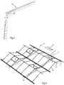
- Fig. 4 shows a window frame 9 which is complementary to the ventilation opening frame 7 and which fits inside the ventilation opening frame 7.
- Figs. 2 and 3 illustrate a possible manner of manufacturing the window frame 9 from four bars which are fixed to each other through gussets.
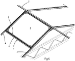
- the window frame 9 is introduced within the ventilation opening frame 7 and held at a fixed position with respect to the ventilation opening frame 7.
- the window frame 9 is held at a fixed position such that neighbouring upper surfaces of the window frame 9 and the ventilation opening frame 7 are substantially flush or the height difference between neighbouring upper surfaces is at least small.
- Fig. 5 shows in more detail a situation in which the window frame 9 is introduced within the ventilation opening frame 7.
- the fixed positions of the window frames 9 with respect to the corresponding ventilation opening frames 7 can be created by temporarily clamping the window frames 9 to the ventilation opening frames 7, for example, but numerous alternative manners are conceivable. For example, temporarily screwing, gluing, lacing, bolting or the like.
- Fig. 6 illustrates a next step in an embodiment of the method according to the invention in which step a transparent foil 10 is laid onto the roof structure 1.
- the transparent foil 10 is supplied from a roll.
- the width of one roll is such that the transparent foil 10 covers the roof structure from one of the gutters 3 to one of the neighbouring ridge beams 2 thereof.
- four strips of the transparent foil 10 are applied to cover the roof structure 1.
- the transparent foil 10 is fixed to the roof structure 1.
- the transparent foil 10 may be tensioned.
- Fig. 6 shows that the transparent foil 10 is fixed to the roof bars 4 by means of respective roof bar strips 11, to the purlins 6 by means of respective purlin strips 12 and to the ridge beams 2 by means of ridge beam strips 13. Consequently, the transparent foil 10 is fixed to the ventilation opening frames 7.
- the transparent foil 10 is also fixed to the gutters 3 by means of gutter strips 14. Furthermore, the transparent foil 10 is fixed to the window frames 9 by means of respective rectangular window frame fastenings 15.
- Figs. 7 and 8 show details of Fig. 6 on a larger scale.
- the mentioned strips 11-14 and the window frame fastenings 15 may be fixed by screws, clamping means, snap fit means, or the like. It is noted that the mentioned strips 11-14 and the window frame fastenings 15 may be made of aluminium, PVC, rubber or the like. It is also possible that the mentioned strips 11-14 and the ribs of the window frame fastenings 15 have identical cross-sections.
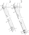
- Figs. 9 and 10 show in detail how the transparent foil 10 is fixed at the window frame 9 and the ventilation opening frame 7. It can be seen that the ventilation opening frame 7 surrounds the window frame 9.
- Fig. 9 shows that the transparent foil 10 is already fixed to the ridge beam 2 through the ridge beam strips 13. Hence, it is already fixed to a portion of the ventilation opening frame 7.
- Fig. 9 also shows that that an upper surface of the purlin 6 and a neighbouring upper surface of the window frame 9 are flush, whereas an upper surface of the ridge beam 2 and a neighbouring upper surface of the window frame 9 have a small height difference. However, the height difference is relatively small, in this case smaller than 25% of the thickness of the window frame 9.
- Fig. 10 shows that the window frame fastening 15 is fixed to the window frame 9 and the purlin strip 12 is fixed to the purlin 6.
- the transparent foil 10 between the window frames 9 and the corresponding ventilation opening frames 7 is cut.
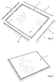
- the window frames 9 including the respective transparent foil 10 and window frame fastenings 15, now mentioned intermediate window inserts and indicated by reference number 9' in the figures, are taken out from the ventilation opening frames 7, see Figs. 11 and 12 .
- each of the intermediate window inserts 9' is provided with a finishing edge in the form of border strips 16 at three outer edges thereof and a first hinge portion in the form of a window hinge strip 17 at one outer edge thereof, which is shown in Fig. 13 .
- the ventilation opening frame 7 is also provided with a finishing edge in the form of border strips 18 at three sides thereof and a second hinge portion in the form of a ventilation opening hinge strip 19, see Fig. 15 .
- the ventilation opening hinge strip 19 is fixed to the remainder of the ridge beam 2, see Fig. 18 .
- a resulting bordered ventilation opening frame is shown in Fig. 16 and indicated by reference number 7'.
- the window hinge strip 17 and the ventilation opening hinge strip 19 are first and second cooperating profiled elongate sections, respectively, which engage each other when mounting the roof window 9'' to the bordered ventilation opening frame 7' such that the roof window 9'' is pivotable with respect to the bordered ventilation opening frame 7' between an open position and a closed position.
- the finishing edges of the roof windows 9'' and the respective bordered ventilation opening frames 7' are such that when the roof windows 9'' are pivotally mounted to the respective bordered ventilation opening frames 7' the roof window 9'' rests on top of the bordered ventilation opening frame 7' in its closed condition. It can be derived from Fig. 18 that the window frame 9 within the roof window 9'' has a higher position with respect to the ventilation opening frame 7 in closed condition of the roof window 9'' than before laying the foil on the roof structure 1.
- the roof windows 9'' may be coupled to a mechanism for opening and closing the roof windows 9".
- Fig. 17 shows the resulting double gable roof of the greenhouse in a situation in which the roof windows 9'' are in an open position.
- the window frame may be adapted such that it remains within the ventilation opening frame after cutting the transparent foil.
- the window frame and the ventilation opening frame may already be pivotally mounted to each other before applying the transparent foil.
- the invention is also applicable to an alternative roof structure, for example comprising a single inclined roof structure including a ridge beam, a gutter and a plurality of parallel roof bars instead of a gable roof structure or a double gable roof structure.
Landscapes
- Life Sciences & Earth Sciences (AREA)
- Environmental Sciences (AREA)
- Engineering & Computer Science (AREA)
- Architecture (AREA)
- Physics & Mathematics (AREA)
- Electromagnetism (AREA)
- Civil Engineering (AREA)
- Structural Engineering (AREA)
- Roof Covering Using Slabs Or Stiff Sheets (AREA)
- Application Of Or Painting With Fluid Materials (AREA)
- Coating Apparatus (AREA)
- Greenhouses (AREA)
Priority Applications (8)
| Application Number | Priority Date | Filing Date | Title |
|---|---|---|---|
| ES20201424T ES2961394T3 (es) | 2020-10-13 | 2020-10-13 | Un método para aplicar una lámina sobre una estructura de techo inclinado |
| EP20201424.7A EP3984352B1 (de) | 2020-10-13 | 2020-10-13 | Verfahren zum aufbringen einer folie auf eine geneigte dachkonstruktion |
| US18/031,108 US12446496B2 (en) | 2020-10-13 | 2021-10-12 | Method of applying a foil on an inclined roof structure |
| MX2023003915A MX2023003915A (es) | 2020-10-13 | 2021-10-12 | Un procedimiento de aplicacion de una lamina sobre una estructura de cubierta inclinada. |
| JP2023546388A JP2023548958A (ja) | 2020-10-13 | 2021-10-12 | 傾斜屋根構造の上にフォイルを施与する方法 |
| PCT/EP2021/078120 WO2022078990A1 (en) | 2020-10-13 | 2021-10-12 | A method of applying a foil on an inclined roof structure |
| AU2021359747A AU2021359747A1 (en) | 2020-10-13 | 2021-10-12 | A method of applying a foil on an inclined roof structure |
| SA523440314A SA523440314B1 (ar) | 2020-10-13 | 2023-04-10 | طريقة لتطبيق رقاقة معدنية على هيكل سقف مائل |
Applications Claiming Priority (1)
| Application Number | Priority Date | Filing Date | Title |
|---|---|---|---|
| EP20201424.7A EP3984352B1 (de) | 2020-10-13 | 2020-10-13 | Verfahren zum aufbringen einer folie auf eine geneigte dachkonstruktion |
Publications (3)
| Publication Number | Publication Date |
|---|---|
| EP3984352A1 true EP3984352A1 (de) | 2022-04-20 |
| EP3984352C0 EP3984352C0 (de) | 2023-08-02 |
| EP3984352B1 EP3984352B1 (de) | 2023-08-02 |
Family
ID=72852404
Family Applications (1)
| Application Number | Title | Priority Date | Filing Date |
|---|---|---|---|
| EP20201424.7A Active EP3984352B1 (de) | 2020-10-13 | 2020-10-13 | Verfahren zum aufbringen einer folie auf eine geneigte dachkonstruktion |
Country Status (8)
| Country | Link |
|---|---|
| US (1) | US12446496B2 (de) |
| EP (1) | EP3984352B1 (de) |
| JP (1) | JP2023548958A (de) |
| AU (1) | AU2021359747A1 (de) |
| ES (1) | ES2961394T3 (de) |
| MX (1) | MX2023003915A (de) |
| SA (1) | SA523440314B1 (de) |
| WO (1) | WO2022078990A1 (de) |
Families Citing this family (2)
| Publication number | Priority date | Publication date | Assignee | Title |
|---|---|---|---|---|
| ES2961394T3 (es) * | 2020-10-13 | 2024-03-11 | Boal Systemen Bv | Un método para aplicar una lámina sobre una estructura de techo inclinado |
| EP4569198A2 (de) * | 2022-08-10 | 2025-06-18 | Sensei AG Holdings, Inc. | Vorgespannte gewächshausplatten |
Citations (5)
| Publication number | Priority date | Publication date | Assignee | Title |
|---|---|---|---|---|
| FR2289111A1 (fr) * | 1974-10-30 | 1976-05-28 | Tosello Ugo | Charpente metallique pour la realisation d'une serre et de la couverture de celle-ci |
| GB2101663A (en) * | 1981-04-24 | 1983-01-19 | Gillian Maureen Fitzpatrick | A greenhouse ventilator |
| FR2830721A1 (fr) * | 2001-10-12 | 2003-04-18 | Rene Ebel | Module de serre, serre obtenue et procede de montage |
| WO2017153782A2 (en) | 2016-03-11 | 2017-09-14 | Evolve Growing Solutions Limited | Structures |
| EP3626047A1 (de) * | 2018-09-20 | 2020-03-25 | Boal Systemen B.V. | Verfahren zum aufbringen eines transparenten folienmaterials auf ein giebeldach eines gewächshauses, eine folienzuführvorrichtung und eine installationsvorrichtung |
Family Cites Families (18)
| Publication number | Priority date | Publication date | Assignee | Title |
|---|---|---|---|---|
| US4262656A (en) * | 1979-02-28 | 1981-04-21 | Chris Esposito | Solar climate control for greenhouses |
| US4915022A (en) * | 1987-09-08 | 1990-04-10 | Lynch Gary M | Vent assemblies |
| US5410844A (en) * | 1988-08-16 | 1995-05-02 | Lynch; Gary M. | Building vent assembly |
| US5655335A (en) * | 1995-07-07 | 1997-08-12 | Vermeer; Arthur Anthony | Greenhouse structures and roof structures therefor |
| JPH09121692A (ja) | 1995-11-08 | 1997-05-13 | Showa Alum Corp | 温 室 |
| ES2195685B1 (es) | 2000-06-06 | 2004-12-16 | Construcciones De Invernaderos Sanchez, S.L. | Maquina para tendido de cubiertas de invernadero y el correspondiente metodo de instalacion de cubierta. |
| US6832448B2 (en) * | 2002-07-05 | 2004-12-21 | Robert Stefan | Greenhouse |
| JP4142988B2 (ja) | 2003-06-17 | 2008-09-03 | 東都興業株式会社 | 温室の換気装置 |
| US20060248807A1 (en) * | 2005-04-15 | 2006-11-09 | Rough Brothers, Inc. | Greenhouse |
| FR2897604B1 (fr) | 2006-02-22 | 2008-05-09 | Const Metalliques Florentaises | Dispositif pour la mise en place sur un support longitudinal d'au moins un film ou filet par exemple en matiere plastique |
| US8695281B2 (en) * | 2012-05-15 | 2014-04-15 | King Fahd University Of Petroleum And Minerals | Roof reflector |
| KR20160024038A (ko) | 2014-08-22 | 2016-03-04 | 농업회사법인 주식회사 이원 | 비닐온실 만능 작업기 |
| NL2013585B1 (nl) | 2014-10-07 | 2016-10-03 | Boal Systemen Bv | Een kas. |
| WO2017030189A1 (ja) * | 2015-08-20 | 2017-02-23 | こもろ布引いちご園株式会社 | 引張構造の建物 |
| JP6834228B2 (ja) | 2016-08-04 | 2021-02-24 | 大日本印刷株式会社 | フレーム材および農業ハウス |
| ES2961394T3 (es) * | 2020-10-13 | 2024-03-11 | Boal Systemen Bv | Un método para aplicar una lámina sobre una estructura de techo inclinado |
| GB202101076D0 (en) * | 2021-01-27 | 2021-03-10 | Haygrove Ltd | Tunnel structure |
| NL2028269B1 (en) * | 2021-05-21 | 2022-12-06 | Holland Gaas B V | Insect netting for a greenhouse |
-
2020
- 2020-10-13 ES ES20201424T patent/ES2961394T3/es active Active
- 2020-10-13 EP EP20201424.7A patent/EP3984352B1/de active Active
-
2021
- 2021-10-12 WO PCT/EP2021/078120 patent/WO2022078990A1/en not_active Ceased
- 2021-10-12 US US18/031,108 patent/US12446496B2/en active Active
- 2021-10-12 AU AU2021359747A patent/AU2021359747A1/en not_active Abandoned
- 2021-10-12 MX MX2023003915A patent/MX2023003915A/es unknown
- 2021-10-12 JP JP2023546388A patent/JP2023548958A/ja active Pending
-
2023
- 2023-04-10 SA SA523440314A patent/SA523440314B1/ar unknown
Patent Citations (5)
| Publication number | Priority date | Publication date | Assignee | Title |
|---|---|---|---|---|
| FR2289111A1 (fr) * | 1974-10-30 | 1976-05-28 | Tosello Ugo | Charpente metallique pour la realisation d'une serre et de la couverture de celle-ci |
| GB2101663A (en) * | 1981-04-24 | 1983-01-19 | Gillian Maureen Fitzpatrick | A greenhouse ventilator |
| FR2830721A1 (fr) * | 2001-10-12 | 2003-04-18 | Rene Ebel | Module de serre, serre obtenue et procede de montage |
| WO2017153782A2 (en) | 2016-03-11 | 2017-09-14 | Evolve Growing Solutions Limited | Structures |
| EP3626047A1 (de) * | 2018-09-20 | 2020-03-25 | Boal Systemen B.V. | Verfahren zum aufbringen eines transparenten folienmaterials auf ein giebeldach eines gewächshauses, eine folienzuführvorrichtung und eine installationsvorrichtung |
Also Published As
| Publication number | Publication date |
|---|---|
| AU2021359747A9 (en) | 2024-10-03 |
| AU2021359747A1 (en) | 2023-06-08 |
| ES2961394T3 (es) | 2024-03-11 |
| US12446496B2 (en) | 2025-10-21 |
| US20230371446A1 (en) | 2023-11-23 |
| EP3984352C0 (de) | 2023-08-02 |
| MX2023003915A (es) | 2023-06-28 |
| SA523440314B1 (ar) | 2024-06-05 |
| JP2023548958A (ja) | 2023-11-21 |
| EP3984352B1 (de) | 2023-08-02 |
| WO2022078990A1 (en) | 2022-04-21 |
Similar Documents
| Publication | Publication Date | Title |
|---|---|---|
| US9909352B2 (en) | Prefabricated flashing product | |
| US9605432B1 (en) | Interlocking roof shingle and roofing system | |
| DE69526743T2 (de) | Konturiertes ventilationssystem für metalldächer | |
| US8991116B2 (en) | Roof solar panel for conventional sloping roof and shingle integration | |
| CA1202167A (en) | Skylight sealing | |
| US12446496B2 (en) | Method of applying a foil on an inclined roof structure | |
| DE69519428T2 (de) | Bauelement zum abdichten einer dachhaut bei einer dachdurchführung | |
| CZ329794A3 (en) | Flashing of windows, particularly of dormers | |
| CZ20002279A3 (cs) | Izolační rám | |
| EP3054588A1 (de) | Rahmen zum umschliessen eines fotovoltaiklaminats | |
| AU2034699A (en) | Roof construction | |
| US3828494A (en) | Roof jack | |
| US6952901B2 (en) | Panel mounted shingles assembly with ventilating screen | |
| EP4340593B1 (de) | Insektennetz für ein gewächshaus | |
| SK126295A3 (en) | Ventilation strip | |
| US9745790B2 (en) | Prefabricated flashing product | |
| GB2400868A (en) | Trapezially ridged roofing sheet supporting insulation | |
| DK181292B1 (en) | A roof window system with an improved mounting assembly and method of installing such a roof window system | |
| EP4136962B1 (de) | Ein gewächshaus | |
| EP4023832B1 (de) | Dachfenstersystem mit einem isolierrahmen | |
| EP4023833B1 (de) | Dachfenstersystem mit stabilisierungsanordnung | |
| JP2025158648A (ja) | 換気材及びそれを用いた換気ユニット | |
| JP7022416B2 (ja) | 換気棟構造体及び換気棟構造体に用いられるスペーサー | |
| CA2832861C (en) | Modular roof solar panel for conventional sloping roof and roofing integration | |
| GB2373517A (en) | Roof construction for a conservatory |
Legal Events
| Date | Code | Title | Description |
|---|---|---|---|
| PUAI | Public reference made under article 153(3) epc to a published international application that has entered the european phase |
Free format text: ORIGINAL CODE: 0009012 |
|
| STAA | Information on the status of an ep patent application or granted ep patent |
Free format text: STATUS: THE APPLICATION HAS BEEN PUBLISHED |
|
| AK | Designated contracting states |
Kind code of ref document: A1 Designated state(s): AL AT BE BG CH CY CZ DE DK EE ES FI FR GB GR HR HU IE IS IT LI LT LU LV MC MK MT NL NO PL PT RO RS SE SI SK SM TR |
|
| STAA | Information on the status of an ep patent application or granted ep patent |
Free format text: STATUS: REQUEST FOR EXAMINATION WAS MADE |
|
| 17P | Request for examination filed |
Effective date: 20221017 |
|
| RAV | Requested validation state of the european patent: fee paid |
Extension state: TN Effective date: 20221017 Extension state: MA Effective date: 20221017 |
|
| RBV | Designated contracting states (corrected) |
Designated state(s): AL AT BE BG CH CY CZ DE DK EE ES FI FR GB GR HR HU IE IS IT LI LT LU LV MC MK MT NL NO PL PT RO RS SE SI SK SM TR |
|
| GRAP | Despatch of communication of intention to grant a patent |
Free format text: ORIGINAL CODE: EPIDOSNIGR1 |
|
| STAA | Information on the status of an ep patent application or granted ep patent |
Free format text: STATUS: GRANT OF PATENT IS INTENDED |
|
| RIC1 | Information provided on ipc code assigned before grant |
Ipc: E04D 13/03 20060101ALN20230209BHEP Ipc: A01G 9/24 20060101ALI20230209BHEP Ipc: A01G 9/14 20060101AFI20230209BHEP |
|
| RIC1 | Information provided on ipc code assigned before grant |
Ipc: E04D 13/03 20060101ALN20230210BHEP Ipc: A01G 9/24 20060101ALI20230210BHEP Ipc: A01G 9/14 20060101AFI20230210BHEP |
|
| INTG | Intention to grant announced |
Effective date: 20230314 |
|
| GRAS | Grant fee paid |
Free format text: ORIGINAL CODE: EPIDOSNIGR3 |
|
| GRAA | (expected) grant |
Free format text: ORIGINAL CODE: 0009210 |
|
| STAA | Information on the status of an ep patent application or granted ep patent |
Free format text: STATUS: THE PATENT HAS BEEN GRANTED |
|
| AK | Designated contracting states |
Kind code of ref document: B1 Designated state(s): AL AT BE BG CH CY CZ DE DK EE ES FI FR GB GR HR HU IE IS IT LI LT LU LV MC MK MT NL NO PL PT RO RS SE SI SK SM TR |
|
| REG | Reference to a national code |
Ref country code: GB Ref legal event code: FG4D |
|
| REG | Reference to a national code |
Ref country code: CH Ref legal event code: EP |
|
| REG | Reference to a national code |
Ref country code: DE Ref legal event code: R096 Ref document number: 602020014839 Country of ref document: DE |
|
| REG | Reference to a national code |
Ref country code: IE Ref legal event code: FG4D |
|
| U01 | Request for unitary effect filed |
Effective date: 20230830 |
|
| U07 | Unitary effect registered |
Designated state(s): AT BE BG DE DK EE FI FR IT LT LU LV MT NL PT SE SI Effective date: 20230906 |
|
| REG | Reference to a national code |
Ref country code: GR Ref legal event code: EP Ref document number: 20230401862 Country of ref document: GR Effective date: 20231113 |
|
| U20 | Renewal fee for the european patent with unitary effect paid |
Year of fee payment: 4 Effective date: 20231027 |
|
| PG25 | Lapsed in a contracting state [announced via postgrant information from national office to epo] |
Ref country code: IS Free format text: LAPSE BECAUSE OF FAILURE TO SUBMIT A TRANSLATION OF THE DESCRIPTION OR TO PAY THE FEE WITHIN THE PRESCRIBED TIME-LIMIT Effective date: 20231202 |
|
| PG25 | Lapsed in a contracting state [announced via postgrant information from national office to epo] |
Ref country code: RS Free format text: LAPSE BECAUSE OF FAILURE TO SUBMIT A TRANSLATION OF THE DESCRIPTION OR TO PAY THE FEE WITHIN THE PRESCRIBED TIME-LIMIT Effective date: 20230802 Ref country code: NO Free format text: LAPSE BECAUSE OF FAILURE TO SUBMIT A TRANSLATION OF THE DESCRIPTION OR TO PAY THE FEE WITHIN THE PRESCRIBED TIME-LIMIT Effective date: 20231102 Ref country code: IS Free format text: LAPSE BECAUSE OF FAILURE TO SUBMIT A TRANSLATION OF THE DESCRIPTION OR TO PAY THE FEE WITHIN THE PRESCRIBED TIME-LIMIT Effective date: 20231202 Ref country code: HR Free format text: LAPSE BECAUSE OF FAILURE TO SUBMIT A TRANSLATION OF THE DESCRIPTION OR TO PAY THE FEE WITHIN THE PRESCRIBED TIME-LIMIT Effective date: 20230802 |
|
| PG25 | Lapsed in a contracting state [announced via postgrant information from national office to epo] |
Ref country code: PL Free format text: LAPSE BECAUSE OF FAILURE TO SUBMIT A TRANSLATION OF THE DESCRIPTION OR TO PAY THE FEE WITHIN THE PRESCRIBED TIME-LIMIT Effective date: 20230802 |
|
| REG | Reference to a national code |
Ref country code: ES Ref legal event code: FG2A Ref document number: 2961394 Country of ref document: ES Kind code of ref document: T3 Effective date: 20240311 |
|
| PG25 | Lapsed in a contracting state [announced via postgrant information from national office to epo] |
Ref country code: SM Free format text: LAPSE BECAUSE OF FAILURE TO SUBMIT A TRANSLATION OF THE DESCRIPTION OR TO PAY THE FEE WITHIN THE PRESCRIBED TIME-LIMIT Effective date: 20230802 Ref country code: RO Free format text: LAPSE BECAUSE OF FAILURE TO SUBMIT A TRANSLATION OF THE DESCRIPTION OR TO PAY THE FEE WITHIN THE PRESCRIBED TIME-LIMIT Effective date: 20230802 Ref country code: CZ Free format text: LAPSE BECAUSE OF FAILURE TO SUBMIT A TRANSLATION OF THE DESCRIPTION OR TO PAY THE FEE WITHIN THE PRESCRIBED TIME-LIMIT Effective date: 20230802 Ref country code: SK Free format text: LAPSE BECAUSE OF FAILURE TO SUBMIT A TRANSLATION OF THE DESCRIPTION OR TO PAY THE FEE WITHIN THE PRESCRIBED TIME-LIMIT Effective date: 20230802 |
|
| REG | Reference to a national code |
Ref country code: DE Ref legal event code: R097 Ref document number: 602020014839 Country of ref document: DE |
|
| PG25 | Lapsed in a contracting state [announced via postgrant information from national office to epo] |
Ref country code: MC Free format text: LAPSE BECAUSE OF FAILURE TO SUBMIT A TRANSLATION OF THE DESCRIPTION OR TO PAY THE FEE WITHIN THE PRESCRIBED TIME-LIMIT Effective date: 20230802 |
|
| PLBE | No opposition filed within time limit |
Free format text: ORIGINAL CODE: 0009261 |
|
| STAA | Information on the status of an ep patent application or granted ep patent |
Free format text: STATUS: NO OPPOSITION FILED WITHIN TIME LIMIT |
|
| 26N | No opposition filed |
Effective date: 20240503 |
|
| PG25 | Lapsed in a contracting state [announced via postgrant information from national office to epo] |
Ref country code: IE Free format text: LAPSE BECAUSE OF NON-PAYMENT OF DUE FEES Effective date: 20231013 |
|
| PG25 | Lapsed in a contracting state [announced via postgrant information from national office to epo] |
Ref country code: IE Free format text: LAPSE BECAUSE OF NON-PAYMENT OF DUE FEES Effective date: 20231013 |
|
| U20 | Renewal fee for the european patent with unitary effect paid |
Year of fee payment: 5 Effective date: 20241028 |
|
| PGFP | Annual fee paid to national office [announced via postgrant information from national office to epo] |
Ref country code: CH Payment date: 20241101 Year of fee payment: 5 |
|
| GBPC | Gb: european patent ceased through non-payment of renewal fee |
Effective date: 20241013 |
|
| PG25 | Lapsed in a contracting state [announced via postgrant information from national office to epo] |
Ref country code: GB Free format text: LAPSE BECAUSE OF NON-PAYMENT OF DUE FEES Effective date: 20241013 |
|
| PG25 | Lapsed in a contracting state [announced via postgrant information from national office to epo] |
Ref country code: CY Free format text: LAPSE BECAUSE OF FAILURE TO SUBMIT A TRANSLATION OF THE DESCRIPTION OR TO PAY THE FEE WITHIN THE PRESCRIBED TIME-LIMIT; INVALID AB INITIO Effective date: 20201013 |
|
| PG25 | Lapsed in a contracting state [announced via postgrant information from national office to epo] |
Ref country code: HU Free format text: LAPSE BECAUSE OF FAILURE TO SUBMIT A TRANSLATION OF THE DESCRIPTION OR TO PAY THE FEE WITHIN THE PRESCRIBED TIME-LIMIT; INVALID AB INITIO Effective date: 20201013 |
|
| VS25 | Lapsed in a validation state [announced via postgrant information from nat. office to epo] |
Ref country code: MA Free format text: FAILURE TO ELECT DOMICILE IN THE NATIONAL COUNTRY Effective date: 20231103 |
|
| U20 | Renewal fee for the european patent with unitary effect paid |
Year of fee payment: 6 Effective date: 20251027 |
|
| PG25 | Lapsed in a contracting state [announced via postgrant information from national office to epo] |
Ref country code: TR Free format text: LAPSE BECAUSE OF FAILURE TO SUBMIT A TRANSLATION OF THE DESCRIPTION OR TO PAY THE FEE WITHIN THE PRESCRIBED TIME-LIMIT Effective date: 20230802 |
|
| PGFP | Annual fee paid to national office [announced via postgrant information from national office to epo] |
Ref country code: GR Payment date: 20251029 Year of fee payment: 6 |
|
| PGFP | Annual fee paid to national office [announced via postgrant information from national office to epo] |
Ref country code: ES Payment date: 20251103 Year of fee payment: 6 |
|
| VS25 | Lapsed in a validation state [announced via postgrant information from nat. office to epo] |
Ref country code: MA Free format text: LAPSE BECAUSE OF FAILURE TO SUBMIT A TRANSLATION OF THE DESCRIPTION OR TO PAY THE FEE WITHIN THE PRESCRIBED TIME-LIMIT Effective date: 20230802 |