EP3981320A1 - Enhanced optical and perceptual digital eyewear - Google Patents
Enhanced optical and perceptual digital eyewear Download PDFInfo
- Publication number
- EP3981320A1 EP3981320A1 EP21195364.1A EP21195364A EP3981320A1 EP 3981320 A1 EP3981320 A1 EP 3981320A1 EP 21195364 A EP21195364 A EP 21195364A EP 3981320 A1 EP3981320 A1 EP 3981320A1
- Authority
- EP
- European Patent Office
- Prior art keywords
- wearable optics
- optics device
- clause
- utilized
- wearable
- Prior art date
- Legal status (The legal status is an assumption and is not a legal conclusion. Google has not performed a legal analysis and makes no representation as to the accuracy of the status listed.)
- Pending
Links
- 230000003287 optical effect Effects 0.000 title claims description 85
- 238000000034 method Methods 0.000 claims abstract description 198
- 230000003190 augmentative effect Effects 0.000 claims description 98
- 230000007246 mechanism Effects 0.000 claims description 74
- 238000004891 communication Methods 0.000 claims description 33
- 239000000463 material Substances 0.000 claims description 31
- 238000005286 illumination Methods 0.000 claims description 24
- 230000000386 athletic effect Effects 0.000 claims description 18
- 230000001815 facial effect Effects 0.000 claims description 16
- 230000004270 retinal projection Effects 0.000 claims description 14
- 238000001914 filtration Methods 0.000 claims description 13
- 230000004424 eye movement Effects 0.000 claims description 11
- 238000005457 optimization Methods 0.000 claims description 11
- 238000012549 training Methods 0.000 claims description 2
- 230000001133 acceleration Effects 0.000 claims 1
- 230000004438 eyesight Effects 0.000 abstract description 9
- 238000003384 imaging method Methods 0.000 abstract description 4
- 230000002708 enhancing effect Effects 0.000 abstract description 3
- 210000001508 eye Anatomy 0.000 description 164
- 210000000695 crystalline len Anatomy 0.000 description 140
- 238000005259 measurement Methods 0.000 description 55
- 210000001747 pupil Anatomy 0.000 description 31
- 230000001886 ciliary effect Effects 0.000 description 30
- 210000001525 retina Anatomy 0.000 description 29
- 210000000554 iris Anatomy 0.000 description 28
- 239000011521 glass Substances 0.000 description 21
- 238000005516 engineering process Methods 0.000 description 20
- 239000011159 matrix material Substances 0.000 description 16
- 210000004556 brain Anatomy 0.000 description 13
- 238000001514 detection method Methods 0.000 description 12
- 230000000694 effects Effects 0.000 description 12
- 230000014509 gene expression Effects 0.000 description 12
- 238000013519 translation Methods 0.000 description 11
- 230000007613 environmental effect Effects 0.000 description 9
- 210000003205 muscle Anatomy 0.000 description 9
- 230000000007 visual effect Effects 0.000 description 9
- 238000010586 diagram Methods 0.000 description 8
- 238000005401 electroluminescence Methods 0.000 description 8
- 230000006870 function Effects 0.000 description 8
- 230000001149 cognitive effect Effects 0.000 description 7
- 230000006855 networking Effects 0.000 description 7
- 238000012545 processing Methods 0.000 description 7
- 238000004091 panning Methods 0.000 description 6
- 230000001413 cellular effect Effects 0.000 description 5
- 230000006698 induction Effects 0.000 description 5
- 230000035479 physiological effects, processes and functions Effects 0.000 description 5
- 230000009467 reduction Effects 0.000 description 5
- 238000004458 analytical method Methods 0.000 description 4
- 230000036772 blood pressure Effects 0.000 description 4
- 230000004313 glare Effects 0.000 description 4
- 230000008447 perception Effects 0.000 description 4
- 208000001613 Gambling Diseases 0.000 description 3
- 230000008901 benefit Effects 0.000 description 3
- 210000004087 cornea Anatomy 0.000 description 3
- 210000000883 ear external Anatomy 0.000 description 3
- 230000005684 electric field Effects 0.000 description 3
- 210000000744 eyelid Anatomy 0.000 description 3
- 230000005484 gravity Effects 0.000 description 3
- 238000010295 mobile communication Methods 0.000 description 3
- 230000010287 polarization Effects 0.000 description 3
- 238000001228 spectrum Methods 0.000 description 3
- 238000003860 storage Methods 0.000 description 3
- 239000000126 substance Substances 0.000 description 3
- 238000004140 cleaning Methods 0.000 description 2
- 210000004262 dental pulp cavity Anatomy 0.000 description 2
- 238000002405 diagnostic procedure Methods 0.000 description 2
- 238000005553 drilling Methods 0.000 description 2
- 210000003027 ear inner Anatomy 0.000 description 2
- 238000000605 extraction Methods 0.000 description 2
- 210000004709 eyebrow Anatomy 0.000 description 2
- 230000008921 facial expression Effects 0.000 description 2
- 210000003128 head Anatomy 0.000 description 2
- 230000004886 head movement Effects 0.000 description 2
- 230000036541 health Effects 0.000 description 2
- 230000006872 improvement Effects 0.000 description 2
- 238000012986 modification Methods 0.000 description 2
- 230000004048 modification Effects 0.000 description 2
- 229920001690 polydopamine Polymers 0.000 description 2
- 230000008569 process Effects 0.000 description 2
- 230000001953 sensory effect Effects 0.000 description 2
- 230000013707 sensory perception of sound Effects 0.000 description 2
- 238000001356 surgical procedure Methods 0.000 description 2
- 238000012360 testing method Methods 0.000 description 2
- 238000002604 ultrasonography Methods 0.000 description 2
- LFQSCWFLJHTTHZ-UHFFFAOYSA-N Ethanol Chemical compound CCO LFQSCWFLJHTTHZ-UHFFFAOYSA-N 0.000 description 1
- 241000549343 Myadestes Species 0.000 description 1
- 208000010340 Sleep Deprivation Diseases 0.000 description 1
- 238000013459 approach Methods 0.000 description 1
- 230000004397 blinking Effects 0.000 description 1
- 210000000988 bone and bone Anatomy 0.000 description 1
- JLQUFIHWVLZVTJ-UHFFFAOYSA-N carbosulfan Chemical compound CCCCN(CCCC)SN(C)C(=O)OC1=CC=CC2=C1OC(C)(C)C2 JLQUFIHWVLZVTJ-UHFFFAOYSA-N 0.000 description 1
- 230000008859 change Effects 0.000 description 1
- 238000006243 chemical reaction Methods 0.000 description 1
- 239000002131 composite material Substances 0.000 description 1
- 230000003750 conditioning effect Effects 0.000 description 1
- 230000008602 contraction Effects 0.000 description 1
- 238000003745 diagnosis Methods 0.000 description 1
- 230000008030 elimination Effects 0.000 description 1
- 238000003379 elimination reaction Methods 0.000 description 1
- 230000008451 emotion Effects 0.000 description 1
- 238000004880 explosion Methods 0.000 description 1
- 210000000887 face Anatomy 0.000 description 1
- 230000005057 finger movement Effects 0.000 description 1
- 210000001061 forehead Anatomy 0.000 description 1
- 238000009434 installation Methods 0.000 description 1
- 230000010354 integration Effects 0.000 description 1
- 210000001847 jaw Anatomy 0.000 description 1
- 238000011093 media selection Methods 0.000 description 1
- 230000005055 memory storage Effects 0.000 description 1
- 238000002156 mixing Methods 0.000 description 1
- 230000001681 protective effect Effects 0.000 description 1
- 230000005855 radiation Effects 0.000 description 1
- 238000011160 research Methods 0.000 description 1
- 238000012552 review Methods 0.000 description 1
- 210000003625 skull Anatomy 0.000 description 1
- 208000024891 symptom Diseases 0.000 description 1
- 230000009466 transformation Effects 0.000 description 1
- 210000003462 vein Anatomy 0.000 description 1
Images


Classifications
-
- G—PHYSICS
- G06—COMPUTING; CALCULATING OR COUNTING
- G06F—ELECTRIC DIGITAL DATA PROCESSING
- G06F3/00—Input arrangements for transferring data to be processed into a form capable of being handled by the computer; Output arrangements for transferring data from processing unit to output unit, e.g. interface arrangements
- G06F3/01—Input arrangements or combined input and output arrangements for interaction between user and computer
- G06F3/011—Arrangements for interaction with the human body, e.g. for user immersion in virtual reality
- G06F3/013—Eye tracking input arrangements
-
- G—PHYSICS
- G02—OPTICS
- G02B—OPTICAL ELEMENTS, SYSTEMS OR APPARATUS
- G02B27/00—Optical systems or apparatus not provided for by any of the groups G02B1/00 - G02B26/00, G02B30/00
- G02B27/01—Head-up displays
- G02B27/017—Head mounted
-
- G—PHYSICS
- G02—OPTICS
- G02B—OPTICAL ELEMENTS, SYSTEMS OR APPARATUS
- G02B27/00—Optical systems or apparatus not provided for by any of the groups G02B1/00 - G02B26/00, G02B30/00
- G02B27/01—Head-up displays
- G02B27/017—Head mounted
- G02B27/0172—Head mounted characterised by optical features
-
- G—PHYSICS
- G02—OPTICS
- G02B—OPTICAL ELEMENTS, SYSTEMS OR APPARATUS
- G02B5/00—Optical elements other than lenses
- G02B5/30—Polarising elements
-
- G—PHYSICS
- G06—COMPUTING; CALCULATING OR COUNTING
- G06F—ELECTRIC DIGITAL DATA PROCESSING
- G06F1/00—Details not covered by groups G06F3/00 - G06F13/00 and G06F21/00
- G06F1/16—Constructional details or arrangements
- G06F1/1613—Constructional details or arrangements for portable computers
- G06F1/163—Wearable computers, e.g. on a belt
-
- G—PHYSICS
- G02—OPTICS
- G02B—OPTICAL ELEMENTS, SYSTEMS OR APPARATUS
- G02B27/00—Optical systems or apparatus not provided for by any of the groups G02B1/00 - G02B26/00, G02B30/00
- G02B27/01—Head-up displays
- G02B27/0101—Head-up displays characterised by optical features
- G02B2027/0118—Head-up displays characterised by optical features comprising devices for improving the contrast of the display / brillance control visibility
-
- G—PHYSICS
- G02—OPTICS
- G02B—OPTICAL ELEMENTS, SYSTEMS OR APPARATUS
- G02B27/00—Optical systems or apparatus not provided for by any of the groups G02B1/00 - G02B26/00, G02B30/00
- G02B27/01—Head-up displays
- G02B27/0101—Head-up displays characterised by optical features
- G02B2027/0138—Head-up displays characterised by optical features comprising image capture systems, e.g. camera
-
- G—PHYSICS
- G02—OPTICS
- G02B—OPTICAL ELEMENTS, SYSTEMS OR APPARATUS
- G02B27/00—Optical systems or apparatus not provided for by any of the groups G02B1/00 - G02B26/00, G02B30/00
- G02B27/01—Head-up displays
- G02B27/017—Head mounted
- G02B27/0172—Head mounted characterised by optical features
- G02B2027/0174—Head mounted characterised by optical features holographic
-
- G—PHYSICS
- G02—OPTICS
- G02B—OPTICAL ELEMENTS, SYSTEMS OR APPARATUS
- G02B27/00—Optical systems or apparatus not provided for by any of the groups G02B1/00 - G02B26/00, G02B30/00
- G02B27/01—Head-up displays
- G02B27/017—Head mounted
- G02B2027/0178—Eyeglass type
-
- G—PHYSICS
- G02—OPTICS
- G02B—OPTICAL ELEMENTS, SYSTEMS OR APPARATUS
- G02B27/00—Optical systems or apparatus not provided for by any of the groups G02B1/00 - G02B26/00, G02B30/00
- G02B27/01—Head-up displays
- G02B27/0179—Display position adjusting means not related to the information to be displayed
- G02B2027/0187—Display position adjusting means not related to the information to be displayed slaved to motion of at least a part of the body of the user, e.g. head, eye
Definitions
- the present invention relates generally to wearable optics and more particularly to wearable optics that includes additional functionality.
- Wearable optics is utilized for a variety of purposes. Wearable optics is used for improving one's vision for reading glasses and to protect one's vision.
- a wearable optics device and method of use comprises utilizing dynamic eye tracking with a wearable optics device; wherein parameters personalized to a user can be provided based upon the dynamic eye tracking.
- a wearable optics device comprises a lens and a dynamic eye tracking mechanism in communication with the lens. Parameters personalized to a user can be provided based upon the dynamic eye tracking.
- a method comprises utilizing dynamic eye tracking with a wearable optics device.
- a perceptual optimization is utilized based upon the dynamic eye tracking.
- a wearable optics device comprises a lens and a dynamic eye tracking mechanism in communication with the lens.
- a perceptual optimization is utilized based upon the dynamic eye tracking.
- a method comprises utilizing dynamic eye tracking with a wearable optics device.
- An augmented reality overlay is utilized based upon the dynamic eye tracking.
- a wearable optics device comprises a lens; and a dynamic eye tracking mechanism in communication with the lens.
- An augmented reality overlay is utilized based upon the dynamic eye tracking.
- a method comprises utilizing dynamic eye tracking with a wearable optics device. Augmented reality navigation is utilized based upon the dynamic eye tracking.
- a wearable optics device comprises a lens; and a dynamic eye tracking mechanism in communication with the lens. Augmented reality navigation is utilized based upon the dynamic eye tracking.
- the present invention relates generally to wearable optics and more particularly to wearable optics that includes additional functionality.
- the following description is presented to enable one of ordinary skill in the art to make and use the invention and is provided in the context of a patent application and its requirements.
- Various modifications to the preferred embodiments and the generic principles and features described herein will be readily apparent to those skilled in the art.
- the present invention is not intended to be limited to the embodiments shown, but is to be accorded the widest scope consistent with the principles and features described herein.
- a system and method in accordance with the present invention is directed to a variety of ways to enhance the use of wearable optics devices.
- FIG. 1 is a diagram that illustrates Media focals 100.
- Media focals 100 comprises an information bar 102, receiver 104, digital circuitry 106, frames 108 and lens 110.
- Media focals 100 allow for enhancing the wearable optics for its primary purpose, for example, a digital camera could be placed within the wearable optics to allow for seeing certain of these images.
- the circuitry 106 for the media focals 100 could be placed within the frame 108 of the wearable optics.
- the lens 110 could have a totally reflective surface, or a partially reflective surface using LCDs or the like. In effect the wearable optics could look like see-through glasses, but through the use of the circuitry 106 within the wearable optics it is actually a media focal. Additionally, the wearable optics could incorporate a camera to project the user onto a second lens to achieve a see-through effect.
- an information bar 102 is provided across a portion of the wearable optics which is visible to the user. This information bar 102 is used to convey a variety of types of information.
- Figure 2 comprises an information bar 102' on media focal wearable optics.
- the information bar 102' can be a stock ticker scrolling across the top portion of the wearable optics, as is shown in Figure 2 .
- the information bar 102' is shown displaying a stock ticker, other kinds of information such as song titles, lyrics and the like could be displayed in the information bar.
- This information bar is referred to as E-focals. This information might be provided from a digital receiver through an FM station, through a cellular wireless device, or an MP3 player. Additional functionality of the E-focal will be described with more detail with respect to the cell phone enhancements as well as the music player enhancements.
- One of the key features of the media focals 100 is the use of the media focals to enhance the primary function of the user, that is, being able to more accurately and clearly see the objects.
- a zoom feature circuit to allow for the use of the wearable optics as binoculars. This would allow for the user to see objects more closely based on certain activities of the user.
- the circuitry 106 would be located somewhere in the frame of the glasses to provide this functionality and as circuits became smaller and devices became smaller it would be easier and easier to embed the circuitry that is well known for use for such functions directly within the device.
- the circuitry 106 in the device could be, for example, eye sensors which could be pressure sensors, capacitive sensors or some other type of sensor for allowing the eyes to direct the activities. Eye movement sensors, for example, could be used to activate and control the binocular glasses. Similarly, a digital camera could be put on the glasses that would allow the same kinds of technology to take pictures by the person directly.
- the glasses could be used as a normal corrective lens glass utilizing the digital imagery, so that, for example, a user has a certain prescription that they use with their normal prescription glasses to view an object clearly.
- an optometrist could download the new prescription to the wearable optics such that a digital transformation of the image information is provided which is compatible with the new prescription.
- a method for sensing and controlling the digital media could be implemented in a variety of ways.
- an activity of the eye itself would control the activity of the media focal. So, for example, if the idea was to zoom the image, the eye would blink twice. It would also be possible to detect facial and eye movements (squinting, for example), as well as changes in the pupil and iris.
- the eyeglasses in accordance with the present invention would be possible for the eyeglasses in accordance with the present invention to function within a client/server model or Bluetooth (Wi-Fi) model.
- Wi-Fi Wi-Fi
- Utilization of the client/server model and Bluetooth Wi-Fi would make possible, for example, the display of live news or special reports (such as financial reports) from the Internet or similar sources on the eyeglasses. This would also allow for portions of circuitry to be located remotely such that less circuitry in the wearable optics is required.
- the wearable optics could also include a logo, for example, law enforcement officers could have their glasses emblazoned with "Police”, “Sheriff”, “MP”, etc.; young people could have their eyeglasses emblazoned with words and images that reflected their favorite performers, etc.; sports teams could offer the eyeglasses at discount with team monograms, etc. They could also be purchased by companies, emblazoned with the company logos, and given out as retirement gifts, etc.
- Figure 3 is a block diagram of wearable optics 300 that is utilized in a music environment such as an MP3 player.
- Figure 3 comprises wearable optics 300, an information bar 302, MP3 player circuitry 304, storage 306, frames 308, and one or a plurality of lenses 310.
- Another environment as has been above described is the music environment. What would be desirable would be to provide music glasses in which an MP3 player on an IPod or the like is incorporated in the wearable optics, either in a wired or wireless environment.
- a plurality of users could be networked via an MP3 player type environment within a hotspot, or the like, which would allow one to have downloads of whatever music is required through the eyeglasses.
- the system could allow for downloadable music which could be selected via scrolling and the like through voice recognition systems.
- the eyeglasses could link to a multimedia network, authorize downloading and billing for selected music.
- access to a plurality of libraries for music selections could be provided.
- the wearable optics could also be utilized in conjunction with wireless technology to allow a user or a plurality of users to participate simultaneously in single or group karaoke singing.
- the wearable optics could be used specifically to display the lyrics of a song, melody, notes, name of the song or other associated references.
- the headphones can be either digital or analog.
- the user doesn't need to have 10,000 songs, for example. They can come enrolled in an in-song virtual network library upon entering a hotspot. Therefore, the local storage 306 could be limited. In addition, this would provide location identity information for one who is using the network.
- the songs can be streamed as well as downloaded. The songs could be purchase using the wearable optics.
- the system could be scalable; depending upon what kind of device was being used.
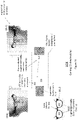
- Figure 4 is a block diagram that illustrates wearable optics that is utilized as a cell phone 400.
- Figure 4 comprises cellular phone circuitry 402, a microphone 104, frames 408 and one or a plurality of lenses 410.
- the cell phone wearable optics 400 could be implemented utilizing digital telephone technology.
- Circuitry 402 within the wearable optics could be utilized to allow a telephone number or other visual information such as that provided by multimedia messaging services to be displayed on the lens 410 of the wearable optics as shown in Figure 3 .
- Figure 5 is a block diagram that illustrates the cellular phone circuitry of Figure 4 .
- Figure 5 comprises noise cancelling circuitry 502, voice recognition circuitry 504, caller ID circuitry 506 and speaker recognition circuitry 508 and media processing circuits 509.
- the telephone number could be activated via the digital circuitry 402 as part of the media focals 100.
- the circuitry could be made truly digital via a digital signal processor which is coupled to a camera otherwise in the environment.
- the above system would allow for voice recording through use of a microphone 104 and would allow for voice recognition through use of the voice recognition circuitry 504, which would allow for signal conditioning on the cell phone in a variety of ways.
- the cell phone environment 402 provides a plurality of areas for improvement utilizing existing technologies.
- one of the major annoyances in cell phone use is that the users have to speak in a loud manner because of background noise and the like.
- There are a variety of reasons for this problem including the placement of the microphone of the cell phone relative to the speaker's mouth, due to the aforementioned background noise, and other issues.
- the microphone could also be located in flip down microphones.
- noise canceling circuitry 502 could be utilized to remove the background noise.
- the microphone capability would include the advantage of utilizing noise rejection techniques. Buttons located on the wearable optics can be utilized to control features thereon.
- the microphone 104 could utilize whisper technology such that the speaker will not have to speak as loudly.
- the wearable optics would in a preferred embodiment include voice recognition circuitry 504 and caller ID circuitry 506.
- the conventionality for hearing and talking in a preferred embodiment would be located in ear and nose pad portions of glasses.
- the electronics for the cell phone in a preferred embodiment would be within the frame 308 of the wearable optics.
- the wearable optics would include a fully integrated information bar 302.
- a speaker recognition algorithm 508 as shown in Figure 5 would allow only the voice of the user to be recognized and the background noise would be cancelled. Accordingly, the unique characteristics of the speaker are provided via an audible model.
- a digital client/server or Bluetooth/wifi model could be adapted to link the wearable optics to external communication equipment.
- Such equipment could include digital cell phones, PDAs or wifi enabled PCs or other devices.
- Such an embodiment could enable review of voicemail, screen viewed emails, text to speech audio email conversions, multimedia messaging services, and other data sources.
- Wireless or Bluetooth interconnection could also make possible VOIP glasses to be utilized instead of a cell phone.
- Other features enabled by a wireless link could link the eyewear to MP3 devices, an iPod, a printer, wireless/wired TV, coupons, and the like.
- PDA glasses could provide built in a time display, alarm calendar, interfacing with PCs or network sources, a speaker and the like.
- digital eyewear is a rapidly evolving field with from the early innovation of digital eyewear with eye tracking capabilities thru Lewis ('185 filed Feb 2008), to eyewear with more complex lenses and communication/display capabilities (Lewis '556, filed Nov 2009), to more enhancements and capabilities (Lewis '594, filed April 2011).
- This enhanced digital eyewear can be used to solve important areas ranging from superior vision enhancement and mobile advertising, to use in dental/medical procedures and physical and Internet navigation.
- the application and value of the enhanced eyewear is increased even further when combined with augmented reality, social networking, messaging, and communications.
- a key feature associated with these enhancements is providing a variety of perceptual parameters that can be utilized with the wearable optics devices.
- perceptual parameters include but are not limited to optical expression, voice, brain wave, environmental, audio, video, navigational, augmented reality, algorithmic, spatial, cognitive, interpretive.
- Figure 5B illustrates a perceptual optimization system 550.
- the perceptual optimization system 550 receives a variety of inputs including optical parameter measurements, real world inputs, digital media inputs, expression parameter measurements, optical parameter measurement feedback, other parameter measurements to provide wearable optics visual display elements.
- Optical parameter measurements include for example, ciliary, pupil, corneal, lens, iris, eye lid, retina measurements.
- Real world inputs could be for example inputs from one or more microphones or cameras.
- Digital media inputs could be for example from digital audio, digital video, graphics, images and augmented reality.
- perceptual parameters could be for example, smell, touch, brainwave, temperature/humidity of the user, environmental conditions near the user.
- the optical feedback could be provided through information received about the retina/iris dynamics and/or the lens ciliary dynamics.
- FIG. 5C illustrates a wearable optics device architecture 560 in accordance with an embodiment.
- the architecture includes a frame 562 which includes a plurality of sensors on various areas thereon.
- Biometric sensors include a blood pressure sensor 617, temperature sensor 618, EEG sensor 616 and the like.
- Environmental sensors 615 are also provided.
- microphone sensors 606,607, 611 on various areas of the frame. Included on the frame 562 are cameras rear, front and side 606,607, 611 to detect objects .
- the lens is a lens display 601.
- a display projector 620 is provided thereon to project images on the lens display 601.
- the lens display 601 can be a single unit or multiple unit lens.
- a control communication unit 608 is utilized to control the architecture 560.
- a power unit can be utilized to enable the architecture.
- the power unit 613 comprises a rechargeable battery. The battery can be charged via a connector, such as but not limited to an USB connector to a charging device laptop, tablet or desktop PC for example.
- the device could be solar powered either by solar cells being placed on the device or the solar cells could be placed on articles of clothing (i.e. hat, shirt or pants for example) to facilitate the charging thereof.
- the architecture 560 includes a directional illumination unit 603, smell sensors 605 and an extendable user microphone 619.
- the sensors may comprise any or any combination of gyroscopes, accelerometers, torque sensors, weight sensors, pressure sensors, magnetometers, temperature sensors, light sensor, cameras and microphones, GPS, wireless detection, altitude sensors, blood pressure , heart rate sensors, biometric sensors, radio frequency identification (RFID), near field communication (NFC), mobile communication, Wi-Fi, strain gauges, fingerprint sensors, smell sensors gas sensors, chemical sensors, color sensors, sound sensors, acoustic sensors, ultraviolet sensors, electric field sensors, magnetic field sensors, gravity sensors, wind speed sensors, wind direction sensors, compass sensors, geo-locator sensor, polarized light sensors, infrared emitter sensors.
- RFID radio frequency identification
- NFC near field communication
- Wi-Fi strain gauges
- fingerprint sensors smell sensors gas sensors, chemical sensors, color sensors, sound sensors, acoustic sensors, ultraviolet sensors, electric field sensors, magnetic field sensors, gravity sensors, wind speed sensors, wind direction sensors, compass sensors, geo-locator sensor, polarized light sensors, infrared emitter sensors
- This architecture can be utilized with a conventional mobile operating system such as Android or IOS or with a new operating system incorporating optical parameters and perceptual parameters for even further capabilities and enhanced perception - eye optical or perceptual operating system (eyePOS).
- a whole new class of custom applications (“apps") can be created using the standard mobile operating systems or eyePOS and an eyePOS simulator to address manifold valuable applications that can improve human learning, entertainment, and health on one side to new navigation systems (physically linked and search linked) and enhanced perception.
- a method and system in accordance with an embodiment comprises utilizing dynamic eye tracking with a wearable optics device; wherein parameters personalized to a user can be provided based upon the dynamic eye tracking.
- the method and system which includes providing an enhancement utilizing objective and subjective quality standards based upon perceptual parameters.
- the perceptual parameters include any and any combination of optical expression, voice, brain wave, environmental, audio, video, navigational, augmented reality, algorithmic, spatial, cognitive, interpretive.
- the wearable optics device controls any or any combination of mimics, amplifies, or expands a user perceptual physiology utilizing perceptual parameters.
- the wearable optics device can include one or more inserts into eyeglasses.
- the eyeglasses comprise quad state eyeglasses.
- Shading control can be utilized on the wearable optics device.
- the shading control can be provided by one or more projectors within the wearable optics device.
- An occlusion effect can be projected on a lens of the wearable optics device.
- the shading can be provided on a lens of the wearable optics device wherein the surrounding area is occluded or reversed.
- the shading is provided by a polarized filter.
- the shading control can be provided by the lenses within the wearable optics device.
- the shading can be controlled using optical parameters.
- the optical parameters include any or any combination of ciliary, pupil, corneal, lens, iris, eye lid, and retina measurements.
- the lens can be any or any combination of transparent LCD, LED, OLED, flexible LED, flexible OLED, transparent matrix, semi-transparent matrix, prism based, holographic , electroluminescence, eletroreflective, dynamic filtering materials.
- the wearable optics device comprises an electrochromatic material.
- one or more elements are utilized within the wearable optics device to provide image information into the eye.
- the one or more elements include any or any combination of a lens projector, retinal projection.
- the retinal projection or projector plus prism provide the occlusion.
- the wearable optics device includes shading control for the eyewear.
- portions of an image viewed by the wearable optics device can be shaded to control brightness.
- the lenses of the wearable optics device can be controlled polarizing, transparent OLED, or projection and prism lenses.
- the parameters my include any or any combination of prescriptions for improving the vision of a user, a zoom feature, a microscope feature, magnifying feature, retinal projection feature.
- the wearable optics device can be utilized in a simulator.
- a focal of the wearable optics device is utilized in conjunction with the dynamic eye tracking.
- the parameters can include any or any combination of a zoom feature, a microscope feature, magnifying feature, illumination feature; a retinal projection feature.
- a 360 degree view can be provided.
- the 360 degree view can be any or any combination of a left or right panning, up and down panning, three dimensional rotations.
- an illumination feature is directed to a specific area based upon the dynamic eyetracking mechanism.
- a wearable optics device camera feature can filter certain light waves for controlled viewing or visual effects.
- the filtering feature can include controlling noise reduction, polarization, and creative effects.
- the wearable optics device feature can include controlling a stability control for facial or object focus.
- optical parameters can be utilized.
- the optical parameters include any of or any combination of ciliary, pupil, corneal, retina, lens, iris measurements.
- An embodiment may include detecting head movement.
- An acoustic wave mechanism may be utilized within the wearable optics device.
- a brain wave mechanism may be utilized within the wearable optics device.
- a magnetic wave mechanism may be utilized within the wearable optics device.
- the wearable optics device can be utilized in a variety environments including but not limited to athletic, gaming, gambling, educational, military, firefighting, medical dental, and the like.
- Figure 6 illustrates the parts of an eye that may be utilized with the eye tracking mechanism of an embodiment.
- the iris, retina cornea, pupil, ciliary, and lens can all be utilized either singly or in combination to enable the dynamic eye tracking mechanism.
- FIG. 7 illustrates a social networking application 700 utilized with the wearable optics device.
- the networks of Facebook, Linked In, Twitter, Salesforce.com, and other networks, as well as the Internet are connected to the wearable optics device.
- Individuals that are "Friends" for example can be identified by a highlight by the wearable optics device. Information about individuals can be gathered by using eyes utilized by the wearable optics device architecture. In an embodiment, the individual can be selected. The individual can be identified in a variety of ways for example using facial recognition, target individual information, GPS, RFID, NFC, optical information, voice recognition, and mobile location.
- FIG. 8 illustrates a messaging application 800 utilized with wearable optics device in accordance with an embodiment.
- information is transmitted via mobile, text, R2R, Internet, Wi-Fi, Facebook message, Twitter's tweet.
- the wearable optics device can utilize R2R, NFC, Wi-Fi, Internet to communicate. It is possible to talk using a microphone, sensors near the face, jaw, and nose can be utilized to provide control of the messaging application. In addition lip motion, and lip reading can be utilized to transmit voice in a silent and confidential manner. An individual can be targeted by using selected eye movements.
- Figure 9 illustrates the wearable optics device utilized by an athletic sports spectator in accordance with an embodiment 900.
- Networks such as Twitter, Facebook, Internet are connected to the spectator. For example the spectator can see who has the ball and its course during a play. Who has the ball as well as the ball's location is highlighted.
- Video information can be overlayed from scores of other games. Information about the location of the football during the game (line of scrimmage, first down line). Video highlights of the game could be provided as well as augmented reality media.
- Figure 10 illustrates the wearable optics device utilized by an athletic sports player in accordance with an embodiment 1000.
- Networks such as Twitter, Facebook, Coach/trainer communication, and other player communications are connected to the player.
- the spectator can see that a curve ball is hit at 102 mph. The trajectory of the ball is highlighted.
- Figure 11 illustrates an augmented reality information, navigation, and advertising application 1100 utilized with the wearable optics device.
- information is transmitted via mobile, text, R2R, Internet, Wi-Fi, Facebook message, Twitter's tweet.
- the wearable optics device can utilize mobile, R2R, NFC, Wi-Fi, Internet to communicate.
- the wearable optics device is utilized in a vehicle.
- the wearable optics device includes speaker microphone and rear camera on the headset and also on the rear of a vehicle for example.
- Augmented reality real time information is provided.
- the Augmented Reality Real time information provided is that the vehicle is traveling at 62 mph.
- Augmented Reality Mirror Live Video from Rear Camera of the car.
- Augmented Reality Mirror Live Video from Rear Camera of the car.
- "Detour 1 Mile” is shown on as an emergency Augmented Reality sign from State/Federal Sources which could also provide additional information.
- Figure 12 illustrates an augmented reality information patient data application 1200 utilized with the wearable optics device used in conjunction with a remote device.
- information is transmitted via mobile, text, R2R, Internet, Wi-Fi, Facebook message, Twitter's tweet.
- the wearable optics device can utilize mobile, R2R, NFC, Wi-Fi, Internet to communicate.
- Patient records and internet technical information are connected to the eyepiece and microphone of the person who is utilizing the wearable optics device. Utilizes an augmented reality zoom window to identify medical feature. Augmented reality patient data is made available to the person via the eyewear. There may also be a remote device camera utilized on the drill of a dentist for example. The dentist for example can utilize the dynamic eye tracking mechanism to focus on the correct tooth.
- An overlay of the x-ray of the tooth can be seen utilizing the augmented reality.
- An augmented reality overlay of dental records and Internet research in tooth treatment is available. Dentist can use a remote drill with augmented reality. Illumination and zoom can also be utilized with an augmented reality window.
- Figure 13 illustrates a shading control application 1300 utilized with the wearable optics device.
- information is transmitted via mobile, text, R2R, Internet, Wi-Fi, Facebook message, Twitter's tweet.
- the wearable optics device can utilize mobile, R2R, NFC, Wi-Fi, Internet to communicate.
- Shading settings can be chosen through push buttons on the eyewear frame, via eye movement, or automatically.
- the shading can be uniform across the eyewear lens or concentrated in a specific area or areas of the lens.
- a lamp/flashlight 1302 projects light to eye1310.
- the camera 1306 and eye sensor 1308 pick up the light.
- the lens 1304 can be any or any combination of transparent LCD, LED, OLED, flexible LED, flexible OLED, transparent matrix, semi-transparent matrix, prism based, holographic , electroluminescence, eletroreflective, dynamic filtering materials.
- Light can be occluded in a specific area 1312 utilizing the wearable optics device.
- the camera 1306 determines position of light to be occluded (real time).
- the eye sensor 1308 determines the position of the eye/pupil/retina (real time).
- the camera1306 /eye sensor 1308 determines line of sight between light to be occluded and eye 1310 and intersect area on lens 1304 (real time) or area to project occlusion from a projector embodiment.
- Figure 14 illustrates an augmented reality application1400 utilized with the wearable optics device 1410.
- information is transmitted via mobile, text, R2R, Internet, Wi-Fi, Facebook message, Twitter's tweet.
- the wearable optics device 1410 can utilize mobile, R2R, NFC, Wi-Fi, Internet to communicate.
- an augmented reality keyboard 1404 appears selected by look at the phone/item and then blinking or the like.
- the augmented reality (AR) keyboard 1404 is utilized that is controlled by the dynamic eye tracking mechanism.
- An infrared camera 1402 is used to sense the position of any of the user's hand, hand movement, finger position, finger movement on the AR keyboard such as key highlight and key click sound.
- There is also an augmented reality keyboard which is shown as being on the lens.
- Figure 15 illustrates a physical gaming application 1500 utilized with the wearable optics device 1510.
- information is transmitted via mobile, text, R2R, Internet, Wi-Fi, Facebook message, Twitter's tweet.
- the wearable optics device 1510 can utilize mobile, R2R, NFC, Wi-Fi, Internet to communicate.
- a person wearing the wearable optics device 1510 can analyze game strategy, count cards, determine the score, do analysis (of game statistics), and analyze other player's faces utilizing an augmented reality overlay 1502 and facial recognition.
- Figure 16 illustrates a first embodiment of an online/mobile gaming application 1600 utilized with the wearable optics device 1610.
- information is transmitted via mobile, text, R2R, Internet, Wi-Fi, Facebook message, Twitter's tweet.
- the wearable optics device 1610 can utilize mobile, R2R, NFC, Wi-Fi, Internet to communicate.
- the player and opponent have augmented reality cards in hand.
- Augmented reality playing cards are utilized. Because of the augmented reality and communication link the players need not be present in the same location.
- the AR cards may be lifted by hand movement.
- an infrared camera 1602 on the glasses to measure and judge hand and finger position and movement.
- an augmented reality scene or dynamics overlay 1612 which can be seen on the lenses.
- Figure 17 illustrates a second embodiment of an online/mobile gaming application 1700 utilized with the wearable optics device 1710.
- information is transmitted via mobile, text, R2R, Internet, Wi-Fi, Facebook message, Twitter's tweet.
- the wearable optics device 1710 can utilize mobile, R2R, NFC, Wi-Fi, Internet to communicate.
- the scene that the player sees can be an actual real-world video game screen. It could also be utilized as an augmented reality video game screen (e.g. for mobile). Furthermore it could also be utilized as a full 3-D real time Augmented Reality game/battle field which the player sees.
- the player can use an augmented reality game controller. There is an infrared camera on the glasses to measure and judge hand and finger position and movement on the AR game controller. Augmented reality scenes, AR game controller, AR gun, or AR remote control overlay 1712 are seen on the lenses of the glasses.
- Figure 18 illustrates shading control mechanism utilizing the wearable optics device.
- Figure 19 illustrates an optical/perceptual operating system 1900 with the wearable optics device. As is seen a plurality of applications 1902-1910 interface with a processing system.
- the processing system includes a CPU, Memory, computer control and a CPU updating system 1912.
- the applications include but are not limited to an eye prescription 1902, shading 1904, a glare application, 1906, GPS for navigation of a vehicle 1908 and a medical application 1910.
- the system would include perceptual measurement/generators 1914. These would include but are not limited to calibration software, augmented reality software, entertainment software, video/audio conferencing software and external communication/databases.
- the system would also include one or more device drivers. They include but are not limited to display drivers 1916, optical/sensor drivers 1918, operating system drivers 1920, network drivers 1922, external remote object drivers 1924 and gaming/entertainment drivers 1926.
- Figure 20 describes an embodiment of the digital architecture of a wearable optics device 2000.
- the wearable optics device eyewear includes mobile/smart phone circuitry / external data communication / and circuitry for transmitting data via mobile, text, R2R, Internet, Wi-Fi, Facebook message, Twitter's tweet, along with networking to external networks platforms / data / media sites 2016 .
- the wearable optics contains a processing system 2002 with memory storage, sensors for optical and perceptual measurement 2006, circuitry to control the optical display and perceptual generation needs of the device 2004, and interface 2008 to remote devices such as tools, specialty camera, GPS, mobile phone, wearable devices and the like.
- various types of application software (“apps”) 2018 can be run on the wearable optics device 2000 including shading control applications, focus and user eye adjustment prescriptions, and augmented reality applications for games such as football.
- An Internet browser 2010 that utilizes optical or perceptual parameters to drive navigation of the Internet can be used such that eye movements or facial expressions can accelerate the browsing process to the desired information.
- the wearable optics device 2000 contains a system browser 2012 with file storage that can be on the device or accessed via one of the networks to the device.
- the device 2000 can be powered by a separate battery (not shown).
- the battery can be charged via a connector, such as but not limited to an USB connector to a charging device laptop, tablet or desktop PC for example.
- the device 200 could be solar powered either by solar cells being placed on the device 2000 or the solar cells could be placed on articles of clothing (i.e. hat, shirt or pants for example) to facilitate the charging thereof.
- Figure 21 illustrates the embodiment of a system simulator 2100 for use by developers of applications and new lenses or expansion of the wearable optics device.
- a simulator for the operating system 2102 there is a simulator for the operating system 2102, a lens simulator 2104, a display 2114, and an eyewear emulator 2116.
- Optical/perceptual measurements 2106, camera signals, and other sensors and measurements are inputs to the simulator.
- the developer apps or new lenses can then be tested for various types of wearable options with various types of operating systems including iOS, Andriod, and general purpose or optimized optical/perceptual operating systems.
- Figure 22A through Figure 22F illustrate an embodiment of inverse shading using the wearable optics device.
- Figure 22A illustrates the problem of glare caused by ambient light which degrades the visibility of a object such as the screen of a mobile phone or laptop.
- Figure 22C describes the iris / pupil contraction due to brightness which degrades retina/cornea and brain view of target object such as a phone screen or the like.
- the phone screen appears dark since ambient light is far brighter than screen.
- Figure 22B illustrates the selection of the target object as in a phone screen via eye or automatically by preferences, rules, camera image capture and object recognition.
- Figure 22D shows eye detection and capture of the object's position and image by a camera on the eyewear.
- Figure 22F shows the resulting elimination or reduction in glare and increase in visibility of the object wherein a shaded or translucent background follows surrounding area object in real time as seen from the user of the wearable optics device.
- Figure 23 illustrates an embodiment of eye tracking illumination and enhanced efficiency utilizing the wearable optics device.
- the line of sight and focal length can be determined and used to control a directional illumination source such that the illumination source illuminates the area corresponding to the area being focused on by the user of the wearable optics device
- Figure 24 illustrates an embodiment of real-time augmented reality overlay 2400 utilizing the wearable optics device.
- information is transmitted via mobile, text, R2R, Internet, Wi-Fi, Facebook message, Twitter's tweet.
- the wearable optics device can utilize mobile, R2R, NFC, Wi-Fi, Internet to communicate.
- the wearable optics device is utilized in a vehicle.
- the driver's eyewear uses augmented reality to overlay advertising signs which can be personalized to the user which appear as if they are normal roadside billboards.
- a real-time updated augmented reality danger sign is posted before a road hazard with the augmented reality sign being generated in real-time using information from the networks connected to the wearable eyewear device.
- This example also shows real-time translation from English to Spanish of navigational warning and advertising signs using augmented reality with the wearable optics device.
- a key feature associated with these enhancements is providing a variety of perceptual parameters that can be utilized with the wearable optics devices.
- perceptual parameters include but are not limited to optical expression, voice, brain wave, environmental, audio, video, navigational, augmented reality, algorithmic, spatial, cognitive, interpretive.
Applications Claiming Priority (3)
| Application Number | Priority Date | Filing Date | Title |
|---|---|---|---|
| US13/841,550 US11428937B2 (en) | 2005-10-07 | 2013-03-15 | Enhanced optical and perceptual digital eyewear |
| PCT/US2014/029553 WO2014144940A2 (en) | 2013-03-15 | 2014-03-14 | Enhanced optical and perceptual digital eyewear |
| EP14763034.7A EP2967324B1 (en) | 2013-03-15 | 2014-03-14 | Enhanced optical and perceptual digital eyewear |
Related Parent Applications (1)
| Application Number | Title | Priority Date | Filing Date |
|---|---|---|---|
| EP14763034.7A Division EP2967324B1 (en) | 2013-03-15 | 2014-03-14 | Enhanced optical and perceptual digital eyewear |
Publications (1)
| Publication Number | Publication Date |
|---|---|
| EP3981320A1 true EP3981320A1 (en) | 2022-04-13 |
Family
ID=51538398
Family Applications (2)
| Application Number | Title | Priority Date | Filing Date |
|---|---|---|---|
| EP14763034.7A Active EP2967324B1 (en) | 2013-03-15 | 2014-03-14 | Enhanced optical and perceptual digital eyewear |
| EP21195364.1A Pending EP3981320A1 (en) | 2013-03-15 | 2014-03-14 | Enhanced optical and perceptual digital eyewear |
Family Applications Before (1)
| Application Number | Title | Priority Date | Filing Date |
|---|---|---|---|
| EP14763034.7A Active EP2967324B1 (en) | 2013-03-15 | 2014-03-14 | Enhanced optical and perceptual digital eyewear |
Country Status (6)
| Country | Link |
|---|---|
| EP (2) | EP2967324B1 (ja) |
| JP (3) | JP2016515897A (ja) |
| KR (1) | KR102391405B1 (ja) |
| CN (2) | CN115981000A (ja) |
| ES (1) | ES2900423T3 (ja) |
| WO (1) | WO2014144940A2 (ja) |
Families Citing this family (48)
| Publication number | Priority date | Publication date | Assignee | Title |
|---|---|---|---|---|
| US10617342B2 (en) | 2014-09-05 | 2020-04-14 | Vision Service Plan | Systems, apparatus, and methods for using a wearable device to monitor operator alertness |
| US10448867B2 (en) | 2014-09-05 | 2019-10-22 | Vision Service Plan | Wearable gait monitoring apparatus, systems, and related methods |
| US11918375B2 (en) | 2014-09-05 | 2024-03-05 | Beijing Zitiao Network Technology Co., Ltd. | Wearable environmental pollution monitor computer apparatus, systems, and related methods |
| US10215568B2 (en) | 2015-01-30 | 2019-02-26 | Vision Service Plan | Systems and methods for tracking motion, performance, and other data for an individual such as a winter sports athlete |
| NZ773822A (en) | 2015-03-16 | 2022-07-29 | Magic Leap Inc | Methods and systems for diagnosing and treating health ailments |
| US10275369B2 (en) | 2015-03-23 | 2019-04-30 | International Business Machines Corporation | Communication mode control for wearable devices |
| KR101756792B1 (ko) * | 2015-07-28 | 2017-07-11 | 재단법인대구경북과학기술원 | Hmd형 가상현실 콘텐츠 모니터링 및 제어 시스템 |
| TWI571240B (zh) * | 2015-09-16 | 2017-02-21 | 國立交通大學 | 抑制腦波雜訊之裝置及其方法 |
| CN105427701B (zh) * | 2015-11-30 | 2018-11-06 | 武汉华瑞密达科教股份有限公司 | 消防业务操作培训系统和方法 |
| CN105511077B (zh) * | 2015-12-19 | 2019-02-01 | 祁刚 | 头戴式智能设备 |
| WO2017114759A1 (fr) * | 2015-12-30 | 2017-07-06 | Essilor International (Compagnie Generale D'optique) | Procédé de commande d'un système ophtalmique à partir d'une mesure et d'une information obtenue par un dispositif électronique externe |
| CN106214118A (zh) * | 2016-01-28 | 2016-12-14 | 北京爱生科贸有限公司 | 一种基于虚拟现实的眼球运动监测系统 |
| EP3440497B1 (en) | 2016-04-08 | 2023-08-16 | Magic Leap, Inc. | Augmented reality systems and methods with variable focus lens elements |
| CN105788390A (zh) * | 2016-04-29 | 2016-07-20 | 吉林医药学院 | 基于增强现实的医学解剖辅助教学系统 |
| TWI597049B (zh) * | 2016-06-01 | 2017-09-01 | 清弘生醫股份有限公司 | 可穿戴式眼溫監測裝置及其系統 |
| KR102493607B1 (ko) * | 2016-06-15 | 2023-02-01 | 삼성전자주식회사 | 지문 인식 기능을 지원하는 전자 장치 및 이의 운용 방법 |
| CN111308714B (zh) * | 2016-07-22 | 2023-02-03 | 蔡清来 | 统合实境智慧眼镜护眼遮光器 |
| CN106324862A (zh) * | 2016-08-22 | 2017-01-11 | 苏州倍声声学技术有限公司 | 一种智能化多功能通信眼镜 |
| WO2018043975A1 (ko) * | 2016-09-03 | 2018-03-08 | 정차균 | 방향 정렬 보조용 골프안경 및 그 동작방법 |
| JP2018042755A (ja) * | 2016-09-14 | 2018-03-22 | 株式会社トプコン | 立体画像提示装置、及び眼科装置 |
| CN106878540A (zh) * | 2016-11-28 | 2017-06-20 | 苏州花坞信息科技有限公司 | 一种具有显示功能的智能眼镜及其控制方法 |
| US9711072B1 (en) * | 2016-12-01 | 2017-07-18 | Varjo Technologies Oy | Display apparatus and method of displaying using focus and context displays |
| CN106725280B (zh) * | 2016-12-22 | 2018-06-05 | 首都医科大学附属北京同仁医院 | 一种斜视度测量装置 |
| IL301881B1 (en) | 2017-02-23 | 2024-04-01 | Magic Leap Inc | Display system with variable power reflector |
| CN106842576A (zh) * | 2017-03-23 | 2017-06-13 | 核桃智能科技(常州)有限公司 | 一种具有移动通讯功能的头戴智能显示设备 |
| US11106274B2 (en) * | 2017-04-10 | 2021-08-31 | Intel Corporation | Adjusting graphics rendering based on facial expression |
| US9910298B1 (en) | 2017-04-17 | 2018-03-06 | Vision Service Plan | Systems and methods for a computerized temple for use with eyewear |
| JP6845072B2 (ja) | 2017-04-21 | 2021-03-17 | ファナック株式会社 | 工場設備の保守支援装置及び保守支援システム |
| US10610179B2 (en) * | 2017-06-05 | 2020-04-07 | Biosense Webster (Israel) Ltd. | Augmented reality goggles having X-ray protection |
| CN107300771B (zh) * | 2017-06-21 | 2019-11-29 | 常州快来信息科技有限公司 | 头戴3d显示设备的视觉优化方法 |
| CN107238003A (zh) * | 2017-07-19 | 2017-10-10 | 广州新诚生物科技有限公司 | 智能头灯 |
| EP3672478A4 (en) | 2017-08-23 | 2021-05-19 | Neurable Inc. | BRAIN COMPUTER INTERFACE WITH HIGH SPEED EYE TRACKING |
| CN107544676A (zh) * | 2017-09-08 | 2018-01-05 | 北京枭龙科技有限公司 | 一种ar眼镜的输入方法 |
| EP3492965A1 (en) * | 2017-12-04 | 2019-06-05 | Essilor International | Optical device and means for detecting driving conditions |
| KR102570401B1 (ko) * | 2018-05-09 | 2023-08-23 | 서강대학교 산학협력단 | 증강현실 기반의 전자책 제공 방법 및 착용형 디스플레이 장치 |
| US10722128B2 (en) | 2018-08-01 | 2020-07-28 | Vision Service Plan | Heart rate detection system and method |
| KR102236534B1 (ko) * | 2018-11-02 | 2021-04-06 | 주식회사 엘지화학 | 편광자의 제조 방법 |
| CN110200606A (zh) * | 2019-05-07 | 2019-09-06 | 谷东科技有限公司 | 一种基于ar眼镜的环境及生命特征监测系统 |
| CN111259135A (zh) * | 2019-09-02 | 2020-06-09 | 北京佳珥医学科技有限公司 | 文本的显示方法、提词器及提词系统 |
| JP7170277B2 (ja) * | 2019-12-09 | 2022-11-14 | 株式会社辰巳菱機 | 通報装置 |
| JP2023511407A (ja) | 2020-01-22 | 2023-03-17 | フォトニック メディカル インク. | 開放視野マルチモード深度検知校正デジタルルーペ |
| KR102322110B1 (ko) * | 2020-05-11 | 2021-11-04 | 공주대학교 산학협력단 | 학습 증진을 위한 안경형 웨어러블 디바이스 |
| IT202100013811A1 (it) * | 2021-05-27 | 2022-11-27 | Jlg Group S R L | Micro fotocamera integrata indossabile |
| WO2022261031A2 (en) * | 2021-06-07 | 2022-12-15 | Percept Technologies, Inc. | Dynamic visual optimization |
| WO2023018908A1 (en) * | 2021-08-11 | 2023-02-16 | MeetKai, Inc. | Conversational artificial intelligence system in a virtual reality space |
| US11955135B2 (en) * | 2021-08-23 | 2024-04-09 | Snap Inc. | Wearable speech input-based to moving lips display overlay |
| WO2023219236A1 (ko) * | 2022-05-10 | 2023-11-16 | 주식회사 비브스튜디오스 | 스마트 안경에 광고를 디스플레이하는 방법 |
| CN117064343B (zh) * | 2023-10-11 | 2023-12-19 | 汉达科技发展集团有限公司 | 一种可检测生命体征的智能ar偏振探测数据处理方法 |
Citations (3)
| Publication number | Priority date | Publication date | Assignee | Title |
|---|---|---|---|---|
| US20120068913A1 (en) * | 2010-09-21 | 2012-03-22 | Avi Bar-Zeev | Opacity filter for see-through head mounted display |
| US20120154277A1 (en) * | 2010-12-17 | 2012-06-21 | Avi Bar-Zeev | Optimized focal area for augmented reality displays |
| US20120242678A1 (en) * | 2010-02-28 | 2012-09-27 | Osterhout Group, Inc. | See-through near-eye display glasses including an auto-brightness control for the display brightness based on the brightness in the environment |
Family Cites Families (26)
| Publication number | Priority date | Publication date | Assignee | Title |
|---|---|---|---|---|
| US4576453A (en) * | 1984-08-03 | 1986-03-18 | Richard Borowsky | Light-occluding contact lens |
| US4659197A (en) * | 1984-09-20 | 1987-04-21 | Weinblatt Lee S | Eyeglass-frame-mounted eye-movement-monitoring apparatus |
| JPH0738848B2 (ja) * | 1990-07-16 | 1995-05-01 | 日本電信電話株式会社 | 視線トレーサ |
| CN2240155Y (zh) * | 1995-01-28 | 1996-11-13 | 周仁荣 | 防眩光眼镜 |
| US5671035A (en) * | 1995-06-07 | 1997-09-23 | Barnes; Elwood E. | Light intensity reduction apparatus and method |
| CN1070614C (zh) * | 1996-03-25 | 2001-09-05 | 王盛荣 | 一种防眩目眼镜 |
| CN2293846Y (zh) * | 1997-02-25 | 1998-10-07 | 黄加玉 | 新型多功能防眩光眼镜 |
| EP1196807A1 (en) * | 1999-07-20 | 2002-04-17 | Smartspecs, L.l.c. | Integrated method and system for communication |
| US7500747B2 (en) * | 2003-10-09 | 2009-03-10 | Ipventure, Inc. | Eyeglasses with electrical components |
| CA2524213A1 (en) * | 2003-04-30 | 2004-11-18 | D4D Technologies, L.P. | Intra-oral imaging system |
| CA2967756C (en) * | 2004-04-01 | 2018-08-28 | Google Inc. | Biosensors, communicators, and controllers monitoring eye movement and methods for using them |
| US20050248722A1 (en) * | 2004-05-04 | 2005-11-10 | Nelis Thomas J | Interactive eye glasses |
| CN101185016A (zh) * | 2005-03-30 | 2008-05-21 | 诺瓦维申公司 | 在视觉训练中用头戴式显示器提供视觉刺激的方法和设备 |
| JP2006309314A (ja) * | 2005-04-26 | 2006-11-09 | Konica Minolta Photo Imaging Inc | 翻訳装置 |
| US20070081123A1 (en) * | 2005-10-07 | 2007-04-12 | Lewis Scott W | Digital eyewear |
| CN101000454A (zh) * | 2006-01-10 | 2007-07-18 | 明基电通股份有限公司 | 由马达驱动设于光源和数字微晶镜片间的遮光罩的投影仪 |
| JP2009034389A (ja) * | 2007-08-02 | 2009-02-19 | Daiichi Shokai Co Ltd | 遊技機 |
| US20100149073A1 (en) * | 2008-11-02 | 2010-06-17 | David Chaum | Near to Eye Display System and Appliance |
| DK2389095T3 (da) * | 2009-01-26 | 2014-11-17 | Tobii Technology Ab | Detektering af blikpunkt hjulpet af optiske referencesignaler |
| JP2011085829A (ja) * | 2009-10-19 | 2011-04-28 | Nikon Corp | ヘッドマウントディスプレイ |
| JP5434499B2 (ja) * | 2009-11-12 | 2014-03-05 | 大日本印刷株式会社 | 柄癖可視化装置、柄癖可視化方法、及びプログラム |
| AU2011220382A1 (en) * | 2010-02-28 | 2012-10-18 | Microsoft Corporation | Local advertising content on an interactive head-mounted eyepiece |
| US8964189B2 (en) * | 2010-08-19 | 2015-02-24 | Canon Kabushiki Kaisha | Three-dimensional measurement apparatus, method for three-dimensional measurement, and computer program |
| US20120056993A1 (en) * | 2010-09-08 | 2012-03-08 | Salman Luqman | Dental Field Visualization System with Improved Ergonomics |
| US8408706B2 (en) * | 2010-12-13 | 2013-04-02 | Microsoft Corporation | 3D gaze tracker |
| US8911087B2 (en) * | 2011-05-20 | 2014-12-16 | Eyefluence, Inc. | Systems and methods for measuring reactions of head, eyes, eyelids and pupils |
-
2014
- 2014-03-14 CN CN202211441297.6A patent/CN115981000A/zh active Pending
- 2014-03-14 KR KR1020157027497A patent/KR102391405B1/ko active IP Right Grant
- 2014-03-14 EP EP14763034.7A patent/EP2967324B1/en active Active
- 2014-03-14 JP JP2016503135A patent/JP2016515897A/ja active Pending
- 2014-03-14 CN CN201480019665.5A patent/CN105142498B/zh active Active
- 2014-03-14 EP EP21195364.1A patent/EP3981320A1/en active Pending
- 2014-03-14 WO PCT/US2014/029553 patent/WO2014144940A2/en active Application Filing
- 2014-03-14 ES ES14763034T patent/ES2900423T3/es active Active
-
2020
- 2020-10-27 JP JP2020179840A patent/JP2021051308A/ja active Pending
-
2023
- 2023-04-06 JP JP2023062245A patent/JP2023113596A/ja active Pending
Patent Citations (3)
| Publication number | Priority date | Publication date | Assignee | Title |
|---|---|---|---|---|
| US20120242678A1 (en) * | 2010-02-28 | 2012-09-27 | Osterhout Group, Inc. | See-through near-eye display glasses including an auto-brightness control for the display brightness based on the brightness in the environment |
| US20120068913A1 (en) * | 2010-09-21 | 2012-03-22 | Avi Bar-Zeev | Opacity filter for see-through head mounted display |
| US20120154277A1 (en) * | 2010-12-17 | 2012-06-21 | Avi Bar-Zeev | Optimized focal area for augmented reality displays |
Also Published As
| Publication number | Publication date |
|---|---|
| EP2967324A4 (en) | 2016-11-09 |
| KR102391405B1 (ko) | 2022-04-27 |
| JP2016515897A (ja) | 2016-06-02 |
| EP2967324A2 (en) | 2016-01-20 |
| WO2014144940A2 (en) | 2014-09-18 |
| EP2967324B1 (en) | 2021-09-08 |
| ES2900423T3 (es) | 2022-03-16 |
| CN115981000A (zh) | 2023-04-18 |
| KR20150140286A (ko) | 2015-12-15 |
| CN105142498B (zh) | 2022-10-11 |
| CN105142498A (zh) | 2015-12-09 |
| JP2021051308A (ja) | 2021-04-01 |
| WO2014144940A3 (en) | 2014-11-06 |
| JP2023113596A (ja) | 2023-08-16 |
Similar Documents
| Publication | Publication Date | Title |
|---|---|---|
| US11630311B1 (en) | Enhanced optical and perceptual digital eyewear | |
| US20230266590A1 (en) | Enhanced Optical and Perceptual Digital Eyewear | |
| US10795183B1 (en) | Enhanced optical and perceptual digital eyewear | |
| CN105142498B (zh) | 增强光学和感知数字护目镜 | |
| US8733927B1 (en) | Enhanced optical and perceptual digital eyewear | |
| WO2014144918A2 (en) | Enhanced optical and perceptual digital eyewear | |
| KR102182605B1 (ko) | 시선-기반 미디어 선택 및 편집을 위한 시스템들 및 방법들 | |
| US9519640B2 (en) | Intelligent translations in personal see through display | |
| JP2013521576A (ja) | 対話式ヘッド取付け型アイピース上での地域広告コンテンツ | |
| US20230229010A1 (en) | Head-mountable device for posture detection | |
| US20240103608A1 (en) | Devices, Methods, and Graphical User Interfaces for Providing Computer-Generated Experiences | |
| US20240118746A1 (en) | User interfaces for gaze tracking enrollment | |
| US20240103617A1 (en) | User interfaces for gaze tracking enrollment | |
| US20240153205A1 (en) | Devices, Methods, and Graphical User Interfaces for Providing Computer-Generated Experiences | |
| WO2023244515A1 (en) | Head-mountable device with guidance features | |
| WO2023205096A1 (en) | Head-mountable device for eye monitoring |
Legal Events
| Date | Code | Title | Description |
|---|---|---|---|
| PUAI | Public reference made under article 153(3) epc to a published international application that has entered the european phase |
Free format text: ORIGINAL CODE: 0009012 |
|
| STAA | Information on the status of an ep patent application or granted ep patent |
Free format text: STATUS: THE APPLICATION HAS BEEN PUBLISHED |
|
| AC | Divisional application: reference to earlier application |
Ref document number: 2967324 Country of ref document: EP Kind code of ref document: P |
|
| AK | Designated contracting states |
Kind code of ref document: A1 Designated state(s): AL AT BE BG CH CY CZ DE DK EE ES FI FR GB GR HR HU IE IS IT LI LT LU LV MC MK MT NL NO PL PT RO RS SE SI SK SM TR |
|
| STAA | Information on the status of an ep patent application or granted ep patent |
Free format text: STATUS: REQUEST FOR EXAMINATION WAS MADE |
|
| 17P | Request for examination filed |
Effective date: 20221013 |
|
| RBV | Designated contracting states (corrected) |
Designated state(s): AL AT BE BG CH CY CZ DE DK EE ES FI FR GB GR HR HU IE IS IT LI LT LU LV MC MK MT NL NO PL PT RO RS SE SI SK SM TR |
|
| REG | Reference to a national code |
Ref country code: HK Ref legal event code: DE Ref document number: 40072448 Country of ref document: HK Ref country code: HK Ref legal event code: DE Ref document number: 40072295 Country of ref document: HK |
|
| STAA | Information on the status of an ep patent application or granted ep patent |
Free format text: STATUS: EXAMINATION IS IN PROGRESS |
|
| 17Q | First examination report despatched |
Effective date: 20240130 |