EP3980302B1 - Raddrehzahlsensor für ein nutzfahrzeug - Google Patents
Raddrehzahlsensor für ein nutzfahrzeug Download PDFInfo
- Publication number
- EP3980302B1 EP3980302B1 EP20732146.4A EP20732146A EP3980302B1 EP 3980302 B1 EP3980302 B1 EP 3980302B1 EP 20732146 A EP20732146 A EP 20732146A EP 3980302 B1 EP3980302 B1 EP 3980302B1
- Authority
- EP
- European Patent Office
- Prior art keywords
- component
- wheel speed
- sensor
- speed sensor
- axis
- Prior art date
- Legal status (The legal status is an assumption and is not a legal conclusion. Google has not performed a legal analysis and makes no representation as to the accuracy of the status listed.)
- Active
Links
- 238000001514 detection method Methods 0.000 claims description 22
- 238000000034 method Methods 0.000 claims description 8
- 239000000463 material Substances 0.000 claims description 7
- 230000000295 complement effect Effects 0.000 claims description 5
- 238000000465 moulding Methods 0.000 claims description 5
- 239000004033 plastic Substances 0.000 claims description 5
- 238000004519 manufacturing process Methods 0.000 claims description 4
- 238000007765 extrusion coating Methods 0.000 claims 3
- 239000002991 molded plastic Substances 0.000 claims 1
- 238000005266 casting Methods 0.000 description 24
- 230000005291 magnetic effect Effects 0.000 description 8
- 238000011161 development Methods 0.000 description 6
- 230000018109 developmental process Effects 0.000 description 6
- 238000009434 installation Methods 0.000 description 4
- 230000001681 protective effect Effects 0.000 description 4
- 230000008859 change Effects 0.000 description 3
- 238000005520 cutting process Methods 0.000 description 2
- 230000000694 effects Effects 0.000 description 2
- 238000011895 specific detection Methods 0.000 description 2
- 230000007704 transition Effects 0.000 description 2
- 230000008901 benefit Effects 0.000 description 1
- 238000002788 crimping Methods 0.000 description 1
- 230000001419 dependent effect Effects 0.000 description 1
- 230000005294 ferromagnetic effect Effects 0.000 description 1
- 230000009347 mechanical transmission Effects 0.000 description 1
- 238000010137 moulding (plastic) Methods 0.000 description 1
- 238000005476 soldering Methods 0.000 description 1
- 238000003466 welding Methods 0.000 description 1
Images


Classifications
-
- G—PHYSICS
- G01—MEASURING; TESTING
- G01P—MEASURING LINEAR OR ANGULAR SPEED, ACCELERATION, DECELERATION, OR SHOCK; INDICATING PRESENCE, ABSENCE, OR DIRECTION, OF MOVEMENT
- G01P3/00—Measuring linear or angular speed; Measuring differences of linear or angular speeds
- G01P3/42—Devices characterised by the use of electric or magnetic means
- G01P3/44—Devices characterised by the use of electric or magnetic means for measuring angular speed
- G01P3/48—Devices characterised by the use of electric or magnetic means for measuring angular speed by measuring frequency of generated current or voltage
- G01P3/481—Devices characterised by the use of electric or magnetic means for measuring angular speed by measuring frequency of generated current or voltage of pulse signals
- G01P3/487—Devices characterised by the use of electric or magnetic means for measuring angular speed by measuring frequency of generated current or voltage of pulse signals delivered by rotating magnets
-
- B—PERFORMING OPERATIONS; TRANSPORTING
- B60—VEHICLES IN GENERAL
- B60T—VEHICLE BRAKE CONTROL SYSTEMS OR PARTS THEREOF; BRAKE CONTROL SYSTEMS OR PARTS THEREOF, IN GENERAL; ARRANGEMENT OF BRAKING ELEMENTS ON VEHICLES IN GENERAL; PORTABLE DEVICES FOR PREVENTING UNWANTED MOVEMENT OF VEHICLES; VEHICLE MODIFICATIONS TO FACILITATE COOLING OF BRAKES
- B60T8/00—Arrangements for adjusting wheel-braking force to meet varying vehicular or ground-surface conditions, e.g. limiting or varying distribution of braking force
- B60T8/32—Arrangements for adjusting wheel-braking force to meet varying vehicular or ground-surface conditions, e.g. limiting or varying distribution of braking force responsive to a speed condition, e.g. acceleration or deceleration
- B60T8/72—Arrangements for adjusting wheel-braking force to meet varying vehicular or ground-surface conditions, e.g. limiting or varying distribution of braking force responsive to a speed condition, e.g. acceleration or deceleration responsive to a difference between a speed condition, e.g. deceleration, and a fixed reference
- B60T8/76—Arrangements for adjusting wheel-braking force to meet varying vehicular or ground-surface conditions, e.g. limiting or varying distribution of braking force responsive to a speed condition, e.g. acceleration or deceleration responsive to a difference between a speed condition, e.g. deceleration, and a fixed reference two or more sensing means from different wheels indicative of the same type of speed condition
-
- B—PERFORMING OPERATIONS; TRANSPORTING
- B60—VEHICLES IN GENERAL
- B60T—VEHICLE BRAKE CONTROL SYSTEMS OR PARTS THEREOF; BRAKE CONTROL SYSTEMS OR PARTS THEREOF, IN GENERAL; ARRANGEMENT OF BRAKING ELEMENTS ON VEHICLES IN GENERAL; PORTABLE DEVICES FOR PREVENTING UNWANTED MOVEMENT OF VEHICLES; VEHICLE MODIFICATIONS TO FACILITATE COOLING OF BRAKES
- B60T8/00—Arrangements for adjusting wheel-braking force to meet varying vehicular or ground-surface conditions, e.g. limiting or varying distribution of braking force
- B60T8/17—Using electrical or electronic regulation means to control braking
- B60T8/171—Detecting parameters used in the regulation; Measuring values used in the regulation
-
- G—PHYSICS
- G01—MEASURING; TESTING
- G01D—MEASURING NOT SPECIALLY ADAPTED FOR A SPECIFIC VARIABLE; ARRANGEMENTS FOR MEASURING TWO OR MORE VARIABLES NOT COVERED IN A SINGLE OTHER SUBCLASS; TARIFF METERING APPARATUS; MEASURING OR TESTING NOT OTHERWISE PROVIDED FOR
- G01D5/00—Mechanical means for transferring the output of a sensing member; Means for converting the output of a sensing member to another variable where the form or nature of the sensing member does not constrain the means for converting; Transducers not specially adapted for a specific variable
- G01D5/12—Mechanical means for transferring the output of a sensing member; Means for converting the output of a sensing member to another variable where the form or nature of the sensing member does not constrain the means for converting; Transducers not specially adapted for a specific variable using electric or magnetic means
- G01D5/14—Mechanical means for transferring the output of a sensing member; Means for converting the output of a sensing member to another variable where the form or nature of the sensing member does not constrain the means for converting; Transducers not specially adapted for a specific variable using electric or magnetic means influencing the magnitude of a current or voltage
- G01D5/142—Mechanical means for transferring the output of a sensing member; Means for converting the output of a sensing member to another variable where the form or nature of the sensing member does not constrain the means for converting; Transducers not specially adapted for a specific variable using electric or magnetic means influencing the magnitude of a current or voltage using Hall-effect devices
-
- G—PHYSICS
- G01—MEASURING; TESTING
- G01P—MEASURING LINEAR OR ANGULAR SPEED, ACCELERATION, DECELERATION, OR SHOCK; INDICATING PRESENCE, ABSENCE, OR DIRECTION, OF MOVEMENT
- G01P1/00—Details of instruments
- G01P1/02—Housings
- G01P1/026—Housings for speed measuring devices, e.g. pulse generator
-
- G—PHYSICS
- G01—MEASURING; TESTING
- G01R—MEASURING ELECTRIC VARIABLES; MEASURING MAGNETIC VARIABLES
- G01R33/00—Arrangements or instruments for measuring magnetic variables
- G01R33/02—Measuring direction or magnitude of magnetic fields or magnetic flux
- G01R33/06—Measuring direction or magnitude of magnetic fields or magnetic flux using galvano-magnetic devices
- G01R33/07—Hall effect devices
- G01R33/072—Constructional adaptation of the sensor to specific applications
Definitions
- the invention relates to a wheel speed sensor for a commercial vehicle, in particular a wheel speed sensor for a commercial vehicle, which is arranged in the area of a brake of a wheel on a chassis of the commercial vehicle.
- wheel speed sensors are known, which are arranged in the area of a wheel of the vehicle in order to record the speed as directly as possible, without deviations due to a mechanical transmission.
- active wheel speed sensors are increasingly being used, which generate signals in the wheel speed sensor that, for example, have a constant amplitude that is independent of the speed.
- a data protocol is therefore already generated in the wheel speed sensor, which, for example transmitted via a bus system, can be evaluated in a control unit. It is also possible to implement diagnostic functions.
- active wheel speed sensors in the commercial vehicle sector, since the thermal load on the sensor in the wheel area is greater than in the car sector and, in particular, Hall sensor chips cannot withstand the thermal load.
- AMR sensors that have a chip with an “Anisotropic MagnetoResistive” effect are used for active wheel speed sensors.
- the AMR sensors have the disadvantage compared to the Hall sensors that they only have a specific detection direction in which a movement of a pulse generator can be detected, whereas conventional Hall sensors are not limited to a specific detection direction, but a movement in any direction can capture. Therefore it is with the Using AMR sensors requires mounting the wheel speed sensors in the vehicle in a predetermined orientation.
- the invention is therefore based on the object of eliminating the above disadvantage and of providing a wheel speed sensor which can also be used in an area with a higher thermal load in a limited installation space.
- a wheel speed sensor for a commercial vehicle has an active pulse sensor with a predetermined detection direction and a housing that is designed to at least partially enclose the pulse sensor.
- the pulse sensor can detect a movement of a pulse generator in the predetermined detection direction, and the wheel speed sensor has an axis, with a direction of the axis being defined so that it is perpendicular to the Detection direction of the pulse sensor is aligned.
- the housing has a first component and a second component, by which the first component can be at least partially enclosed and with which the first component can be at least partially connected in a form-fitting manner.
- the pulse sensor is attached to the first component and the wheel speed sensor has a radial cable outlet which is radial to the axis of the Wheel speed sensor is aligned and which leads a cable out of the wheel speed sensor, the radial cable outlet being formed integrally with the second component so that the cable is led out in a direction other than in the direction of the axis of the wheel speed sensor.
- the first component has, in the direction of the axis, a first region which has a contour other than a rotationally symmetrical contour on its circumference, and the second component has a second region whose inner contour is at least partially complementary to the contour on the circumference of the first region is formed, and the contour on the circumference of the first region each has a shape feature in predetermined angular steps around the axis of the wheel speed sensor, so that the first component is designed such that when connected, an orientation of the first component to the second component in the predetermined Angle steps around the axis can be defined in order to provide a predetermined angle around the axis between the detection direction of the pulse sensor and the radial cable outlet.
- the active pulse sensor is a sensor that detects pulses that are generated by a change in a magnetic field in a detection area of the sensor.
- the change in the magnetic field in the area of the sensor occurs either by introducing a magnetic body, for example a rotating magnet wheel with permanent magnets attached to it, into the detection area or by changing a stationary magnetic field in the area of the sensor.
- the stationary magnetic field is changed by introducing a ferromagnetic body into the detection area.
- a pulse wheel which has teeth and gaps on the circumference, is moved in the detection area of the sensor and the change in the magnetic field is detected by the teeth and gaps moving through the detection area. Both a transition from a tooth to a gap and a transition from a gap to a tooth can be recorded.
- Such a wheel speed sensor makes it possible to variably produce wheel speed sensors with different angular assignments between the detection direction of the pulse sensor and the radial cable outlet, for example in a second component casting tool for the second component.
- the pulse sensor has an AMR sensor.
- the AMR sensor offers high resolution and great accuracy. In addition, compared to other sensors, it is relatively insensitive to oil, dirt and ambient temperatures.
- the first component is designed as a plastic molded part
- the second component is formed by casting a plastic around the first component
- the housing of the wheel speed sensor is formed by molding the first component with the plastic, which forms the second component, such a wheel speed sensor can be produced inexpensively.
- the first component and the second component have the same material.
- Such a wheel speed sensor has the advantage that a thermal expansion coefficient of the materials of the first and second components is the same, so that the occurrence of internal stresses in the housing of the wheel speed sensor is minimized under thermal load.
- the predetermined angular steps are in a range of 80° to 100°, particularly preferably 90°.
- a possibility of producing the wheel speed sensor with such a grid always offers a suitable angular assignment between the detection direction of the pulse sensor and the radial cable outlet for common applications.
- the predetermined angular steps are in a range from 40° to 50°, particularly preferably 45°.
- a possibility of producing the wheel speed sensor with such a grid offers a suitable angular assignment between the detection direction of the pulse sensor and the radial cable outlet for applications with particularly limited installation space.
- a method has the following steps: providing a pre-assembly assembly, which has the first component, the pulse sensor and the cable pre-assembled, in a second-component casting tool for producing the second component including the radial cable outlet; Orienting the first component in the casting tool by introducing one of the mold features into a corresponding counter-mold feature of the second component casting tool such that a desired predetermined angle between the pulse sensor and the radial cable outlet about the axis of the wheel speed sensor is established; Casting around the first component and the cable so that the second component is produced with the radial cable outlet around the first component.
- Such a method makes it possible to variably produce wheel speed sensors with different angular assignments between the detection direction of the pulse sensor and the radial cable outlet in a single casting tool for the second component.
- the method contains additional steps for producing the pre-assembly assembly: casting around busbars in a first component casting tool; Connecting the cable to the busbars; Connecting the pulse sensor to the power rails.
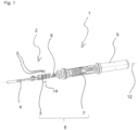
- Fig. 1 shows an exploded view of a wheel speed sensor 1 according to the invention.
- the wheel speed sensor 1 has a pre-assembly assembly 2.
- the pre-assembly assembly 2 has a first component 3, a cable 4, busbars 5 and an active pulse sensor 6, which is attached to the first component 3.
- the pulse sensor 6 has a predetermined detection direction in which a movement of a pulse generator can be detected. This is based on the effect that an electrical resistance of the pulse sensor depends on the presence of a magnetic field and in particular on a direction of the magnetic field.
- the pulse sensor 6 has an AMR sensor.
- the pulse sensor 6 is provided with another sensor with a predetermined detection direction, for example an active Hall sensor.
- the first component 3 is produced by a casting process in which the busbars 5 are cast into the first component 3, so that the first component 3 is designed as a plastic molding.
- the first component 3 points in the direction of one below in connection with Fig. 4 and Fig. 5 defined axis 12 has a first area 14.
- the cable 4 and the pulse sensor 6 are mechanically and electrically connected to the busbars 5 cast in the first component 3.
- the pre-assembly assembly 2 In order to produce the second component 5 around the pre-assembly assembly 2, the pre-assembly assembly 2, and thus the first component 3, is cast with a plastic.
- the second component 7 partially encloses the pulse sensor 6, completely encloses the first component 3 and is connected to the first component 3 in a form-fitting manner.
- the first component 3 and the second component 7 have the same material and form a housing 8 of the wheel speed sensor 1.
- the housing 8 is constructed from other components, with the housing 8 completely or partially enclosing the pulse sensor 6.
- the first component 3 is not completely enclosed by the second component 7 or does not have the same material.
- the wheel speed sensor 1 has a protective cap 9 which partially covers the housing 8.
- Fig. 2 shows a representation of the first component 3 of the wheel speed sensor 1 cast with the second component 7 with a radial cable outlet 10, the cable outlet 10 being designed to lead the cable 4 out of the wheel speed sensor 1.
- Fig. 3 shows an overall representation of the wheel speed sensor 1 from Fig. 2 with installed protective cap 9.
- Fig. 4 shows a schematic sketch of a top view of the wheel speed sensor Fig. 3
- Fig. 5 shows a schematic sketch of a side view of the wheel speed sensor from Fig. 3 to explain a position of an axle 12 of the wheel speed sensor 1.
- the radial cable outlet 10 is formed integrally with the second component 7 so that the cable 4 is led out in a direction other than in the direction of the axle 12.
- the cable outlet 10 is led out radially at a right angle to the axis 12.
- the cable 4 is not led out at a right angle.
- a direction of the axis 12 is defined so that it is aligned perpendicular to a detection direction 11 of the pulse sensor 6.
- the axis 12 corresponds to a central axis of the axisymmetric elongated wheel speed sensor 1.
- a plane 13, which is arranged perpendicular to the axis 12, represents a plane in which the cable 4 extends at different predetermined angles Housing of the wheel speed sensor 1 exits.
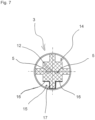
- Fig. 6 shows an enlarged view of the first component 3 with a sectional plane indicated by the arrows A, A.
- Fig. 7 shows an enlarged view of a cross section of the first component 3 in FIG Fig. 6 specified cutting plane AA, i.e. in the first area 14.
- the first area 14 has a contour other than a rotationally symmetrical contour on its circumference.
- the circumference is step-shaped all around and has a shape feature 15 shown with a thick line.
- the shape feature 15 is formed from a shape feature plane 16 and a shape feature web 17, which protrudes from the shape feature plane 16.
- the contour has the shape feature 15 in predetermined angular steps around the axis 12.
- the shape feature 15 is provided here periodically four times in predetermined angular steps of 90°.
- the shape feature 15 can also be provided in 45° increments, or alternatively in angular increments of any size, in particular in a range of 80° to 100° or a range of 40° to 50°.
- Fig. 8 shows an enlarged view of a cross section of a wheel speed sensor 1 from Fig. 3 at the location of the cutting plane AA in Fig. 6 .
- Fig. 8 a cross section of the first region 14 of the first component 3 and a cross section of a second region of the second component 7, the inner contour of which is complementary to the contour on the circumference of the first region 14 of the first component 3, are shown.
- the contours partially match in a complementary manner, with the shape feature 15 matching a complementary part of the contour of the second region of the second component 7.
- an orientation of the first component 3 to the second component 7 can be variably defined in the predetermined angular steps around the axis 12 in order to provide a predetermined angle around the axis 12 between the detection direction 11 of the pulse sensor 6 and the radial cable outlet 10.
- the predetermined angle is provided when the housing 8 is manufactured by recasting, by orienting the pre-assembly assembly 2 in a casting tool.
- the second component 7 consists of two parts which, by clipping together, form the second component 7, which then encloses the first component 3
- a corresponding counter-shape feature of the second component can correspond to the shape feature 15 in the second component 7 be provided in such a way that the predetermined angle is provided by introducing the shape feature 15 into the counter-shape feature of the second component 7.
- busbars are 5 in Fig. 7 and Fig. 8 shown in a state cast in the first component 3.
- the busbars are not cast in the first component 3 but are attached to the first component 3 in a different way.
- the busbars are not absolutely necessary if the cable 4 is connected directly to the pulse sensor 6.
- the pre-assembly assembly 2 is manufactured.
- the busbars 5 are inserted into a first assembly casting tool and then cast in such a way that the first component 3 is formed with the busbars 5 cast therein (see also Figures 7 and 8th ).
- the cable 4 and the pulse sensor 6 are then connected to the busbars 5. This is done via welding, or alternatively via soldering or another suitable connection method, such as crimping.
- the pre-assembly assembly is suitable for being used both for the wheel speed sensor 1 with the radial cable outlet 10 and for the wheel speed sensor 1 with an axial cable outlet.
- the pre-assembly assembly 2 is manufactured in a different way, for example without the busbars 5.
- the pre-assembly assembly 2 which has the first component 3, the pulse sensor 6 and the cable 4, is provided in a second component casting tool for producing the second component 3 including the radial cable outlet 10 by placing it in the second component casting tool is inserted.
- the first component 3 is oriented to the second-component casting tool by introducing one of the shape features 15 into a corresponding counter-shape feature of the second-component casting tool in such a way that the desired predetermined angle between the pulse sensor 6 and the radial cable outlet 10 about the axis 12 is set.
- the shape feature web 17 ( Fig. 7 ) is introduced into a corresponding recess in the second component casting tool.
- This alignment determines the orientation of the pulse sensor 6 in the second component casting tool.
- the pulse sensor 6 can be oriented in a 90° grid. Since the second component casting tool has a mold section for the radial cable outlet 10 at a fixed position, the predetermined angle between the pulse sensor 6 and the radial cable outlet 10 about the axis 12 is thus made possible.
- the cable 4 is then inserted into a receptacle of the second component casting tool, so that the cable 4 is provided in a suitable position so that casting material can be cast around it, the radial cable outlet 10 then being formed.
- the casting material is then filled into the second component casting tool, the first component 3 with the pulse sensor 6 is thereby cast, and the second assembly 7 with the radial cable outlet 10 integrally produced thereon is thereby produced.
Landscapes
- Physics & Mathematics (AREA)
- General Physics & Mathematics (AREA)
- Engineering & Computer Science (AREA)
- Transportation (AREA)
- Mechanical Engineering (AREA)
- Condensed Matter Physics & Semiconductors (AREA)
- Transmission And Conversion Of Sensor Element Output (AREA)
- Injection Moulding Of Plastics Or The Like (AREA)
Applications Claiming Priority (2)
| Application Number | Priority Date | Filing Date | Title |
|---|---|---|---|
| DE102019115397.2A DE102019115397A1 (de) | 2019-06-06 | 2019-06-06 | Raddrehzahlsensor für ein Nutzfahrzeug |
| PCT/EP2020/065452 WO2020245254A1 (de) | 2019-06-06 | 2020-06-04 | Raddrehzahlsensor für ein nutzfahrzeug |
Publications (2)
| Publication Number | Publication Date |
|---|---|
| EP3980302A1 EP3980302A1 (de) | 2022-04-13 |
| EP3980302B1 true EP3980302B1 (de) | 2024-01-10 |
Family
ID=71083604
Family Applications (1)
| Application Number | Title | Priority Date | Filing Date |
|---|---|---|---|
| EP20732146.4A Active EP3980302B1 (de) | 2019-06-06 | 2020-06-04 | Raddrehzahlsensor für ein nutzfahrzeug |
Country Status (6)
| Country | Link |
|---|---|
| US (1) | US20220317143A1 (zh) |
| EP (1) | EP3980302B1 (zh) |
| JP (1) | JP7326489B2 (zh) |
| CN (1) | CN113924232B (zh) |
| DE (1) | DE102019115397A1 (zh) |
| WO (1) | WO2020245254A1 (zh) |
Family Cites Families (22)
| Publication number | Priority date | Publication date | Assignee | Title |
|---|---|---|---|---|
| FR2659450B1 (fr) * | 1990-03-09 | 1994-05-20 | Skf France | Dispositif de moyeu a roulement muni d'un capteur a double detection de la vitesse de rotation. |
| DE19612765A1 (de) * | 1996-03-29 | 1997-11-13 | Teves Gmbh Alfred | Kunststoffsensor und Verfahren zu dessen Herstellung |
| DE19617680A1 (de) * | 1996-05-03 | 1997-11-06 | Teves Gmbh Alfred | Schaltungsanordnung und Vorrichtung zur Erfassung des Drehverhaltens eines Rades |
| DE19625489A1 (de) * | 1996-06-26 | 1998-01-02 | Bosch Gmbh Robert | Drehzahlmeßsystem mit einem umlaufenden bereichsweise magnetisierten Rotor |
| DE19857880B4 (de) * | 1997-12-18 | 2008-07-31 | Honda Lock Mfg. Co., Ltd. | Sensor |
| DE10137294A1 (de) * | 2000-08-02 | 2002-03-14 | Continental Teves Ag & Co Ohg | Kraftfahrzeugmagnetfeldsensoranordnung, Aktivsensor, dessen Verwendung, Verfahren und Vorrichtung |
| JP2004351802A (ja) | 2003-05-29 | 2004-12-16 | Aisin Seiki Co Ltd | インサート成形方法、インサート成形装置、および、インサート成形品 |
| JP4232771B2 (ja) | 2005-09-30 | 2009-03-04 | 株式会社デンソー | 回転検出装置 |
| US7655319B2 (en) * | 2007-02-02 | 2010-02-02 | Continental Automotive Systems Us, Inc. | Plastic positioning pin for overmolded product |
| US7592803B1 (en) | 2008-06-23 | 2009-09-22 | Magic Technologies, Inc. | Highly sensitive AMR bridge for gear tooth sensor |
| KR100931126B1 (ko) * | 2008-06-23 | 2009-12-10 | 현대자동차주식회사 | 휠스피드센서 조립체 |
| KR101033325B1 (ko) * | 2008-12-02 | 2011-05-09 | 현대자동차주식회사 | 휠 스피드 센서 장치 |
| DE102013112813A1 (de) * | 2013-11-20 | 2015-05-21 | Knorr-Bremse Systeme für Nutzfahrzeuge GmbH | Sensoreinrichtung und Scheibenbremse mit einer Sensoreinrichtung |
| DE202013011157U1 (de) * | 2013-12-17 | 2014-02-19 | Continental Teves Ag & Co. Ohg | Sensor mit integrierter Identifikationseinrichtung |
| US10222234B2 (en) * | 2014-06-17 | 2019-03-05 | Infineon Technologies Ag | Rotation sensor |
| DE102014223356A1 (de) * | 2014-11-17 | 2016-05-19 | Robert Bosch Gmbh | Anordnung mit einem Sensor und mit einem elektrischen Kabel |
| DE102015205390A1 (de) * | 2015-03-25 | 2016-09-29 | Robert Bosch Gmbh | Sensoranordnung zur Drehzahlerfassung eines rotierenden Bauteils |
| GB201520343D0 (en) * | 2015-11-18 | 2015-12-30 | Trw Ltd | A position sensor assembly |
| JP2017111002A (ja) | 2015-12-16 | 2017-06-22 | 株式会社デンソー | 回転検出装置 |
| DE102016206389A1 (de) * | 2016-04-15 | 2017-10-19 | Continental Teves Ag & Co. Ohg | Raddrehzahlsensor und Befestigungssystem zur Montage eines Raddrehzahlsensors |
| JP2018128322A (ja) | 2017-02-07 | 2018-08-16 | 株式会社デンソー | 回転検出装置及びその製造方法 |
| CN207208030U (zh) * | 2017-05-22 | 2018-04-10 | 华晨汽车集团控股有限公司 | 一种带有转角传感器的制动踏板总成 |
-
2019
- 2019-06-06 DE DE102019115397.2A patent/DE102019115397A1/de active Pending
-
2020
- 2020-06-04 US US17/596,042 patent/US20220317143A1/en active Pending
- 2020-06-04 CN CN202080041666.5A patent/CN113924232B/zh active Active
- 2020-06-04 JP JP2021572263A patent/JP7326489B2/ja active Active
- 2020-06-04 EP EP20732146.4A patent/EP3980302B1/de active Active
- 2020-06-04 WO PCT/EP2020/065452 patent/WO2020245254A1/de active Application Filing
Also Published As
| Publication number | Publication date |
|---|---|
| DE102019115397A1 (de) | 2020-12-10 |
| US20220317143A1 (en) | 2022-10-06 |
| WO2020245254A1 (de) | 2020-12-10 |
| JP2022536102A (ja) | 2022-08-12 |
| CN113924232B (zh) | 2023-04-14 |
| EP3980302A1 (de) | 2022-04-13 |
| JP7326489B2 (ja) | 2023-08-15 |
| CN113924232A (zh) | 2022-01-11 |
Similar Documents
| Publication | Publication Date | Title |
|---|---|---|
| EP2235552B1 (de) | Verfahren und vorrichtung zur herstellung eines magnetfeldsensors | |
| EP3074730B1 (de) | Sensorherstellung durch halten des zwischenspritzlings | |
| EP2223125B1 (de) | Magnetfeld-sensorelement | |
| DE102006046984A1 (de) | Verfahren zur Herstellung eines Trägerelements mit einem Winkelsensor | |
| EP1040321B1 (de) | Messwertaufnehmer und ein verfahren zu dessen herstellung | |
| DE4405438A1 (de) | Drehzahlgeber | |
| WO2018108470A1 (de) | Sensorvorrichtung sowie verfahren zum zusammenbau einer sensorvorrichtung | |
| EP0984121A2 (de) | Antriebseinrichtung mit einem Stellantrieb | |
| EP1608994B1 (de) | Sensoranordnung einer einparkhilfe | |
| DE19848081A1 (de) | Antriebseinrichtung mit einem Stellantrieb | |
| EP3980302B1 (de) | Raddrehzahlsensor für ein nutzfahrzeug | |
| DE102008014985A1 (de) | Magnetbaugruppe für eine Drehmoment- und/oder Drehwinkelsensoranordnung und Herstellungsverfahren | |
| DE19744673C2 (de) | Vorrichtung zur Erfassung der Drehzahl eines umlaufenden Bauteiles, insbesondere für ein Kraftfahrzeug | |
| DE10129222B4 (de) | Magnetfeldsensor und Verfahren zur Herstellung eines solchen | |
| WO2018224376A1 (de) | Elektronisches bauteil und verfahren zu dessen herstellung | |
| DE102007036241A1 (de) | Geberabdeckung mit Montagering | |
| EP1662262A1 (de) | Drehzahlsensor mit integrierter Elektronik, insbesondere zur Anwendung bei Schienenfahrzeugen | |
| WO2015078628A1 (de) | Werkzeug zum urformen eines gehäuses für einen sensor | |
| EP1391351B1 (de) | Lenkstockmodul und Montageverfahren | |
| WO2018068921A1 (de) | Sensorvorrichtung für ein fahrzeug, kraftfahrzeug | |
| EP3980306B1 (de) | Raddrehzahlsensor für ein nutzfahrzeug | |
| DE102014213590A1 (de) | Kundenspezifischer Adapter für Standardsensor | |
| DE102017210979B4 (de) | Verfahren zur Herstellung eines elektrischen Bauteils und elektrisches Bauteil | |
| DE102020101200A1 (de) | Sensorvorrichtung und Verfahren zu deren Herstellung | |
| DE102008023588A1 (de) | Vorrichtung zur Messung von Drehbewegungen |
Legal Events
| Date | Code | Title | Description |
|---|---|---|---|
| STAA | Information on the status of an ep patent application or granted ep patent |
Free format text: STATUS: UNKNOWN |
|
| STAA | Information on the status of an ep patent application or granted ep patent |
Free format text: STATUS: THE INTERNATIONAL PUBLICATION HAS BEEN MADE |
|
| PUAI | Public reference made under article 153(3) epc to a published international application that has entered the european phase |
Free format text: ORIGINAL CODE: 0009012 |
|
| STAA | Information on the status of an ep patent application or granted ep patent |
Free format text: STATUS: REQUEST FOR EXAMINATION WAS MADE |
|
| 17P | Request for examination filed |
Effective date: 20220107 |
|
| AK | Designated contracting states |
Kind code of ref document: A1 Designated state(s): AL AT BE BG CH CY CZ DE DK EE ES FI FR GB GR HR HU IE IS IT LI LT LU LV MC MK MT NL NO PL PT RO RS SE SI SK SM TR |
|
| DAV | Request for validation of the european patent (deleted) | ||
| DAX | Request for extension of the european patent (deleted) | ||
| GRAP | Despatch of communication of intention to grant a patent |
Free format text: ORIGINAL CODE: EPIDOSNIGR1 |
|
| STAA | Information on the status of an ep patent application or granted ep patent |
Free format text: STATUS: GRANT OF PATENT IS INTENDED |
|
| INTG | Intention to grant announced |
Effective date: 20230822 |
|
| GRAS | Grant fee paid |
Free format text: ORIGINAL CODE: EPIDOSNIGR3 |
|
| GRAA | (expected) grant |
Free format text: ORIGINAL CODE: 0009210 |
|
| STAA | Information on the status of an ep patent application or granted ep patent |
Free format text: STATUS: THE PATENT HAS BEEN GRANTED |
|
| RAP3 | Party data changed (applicant data changed or rights of an application transferred) |
Owner name: KNORR-BREMSE SYSTEME FUER NUTZFAHRZEUGE GMBH |
|
| AK | Designated contracting states |
Kind code of ref document: B1 Designated state(s): AL AT BE BG CH CY CZ DE DK EE ES FI FR GB GR HR HU IE IS IT LI LT LU LV MC MK MT NL NO PL PT RO RS SE SI SK SM TR |
|
| REG | Reference to a national code |
Ref country code: GB Ref legal event code: FG4D Free format text: NOT ENGLISH |
|
| REG | Reference to a national code |
Ref country code: CH Ref legal event code: EP |
|
| REG | Reference to a national code |
Ref country code: DE Ref legal event code: R096 Ref document number: 502020006698 Country of ref document: DE |
|
| REG | Reference to a national code |
Ref country code: IE Ref legal event code: FG4D Free format text: LANGUAGE OF EP DOCUMENT: GERMAN |
|
| REG | Reference to a national code |
Ref country code: SE Ref legal event code: TRGR |
|
| P01 | Opt-out of the competence of the unified patent court (upc) registered |
Effective date: 20240118 |
|
| REG | Reference to a national code |
Ref country code: LT Ref legal event code: MG9D |
|
| REG | Reference to a national code |
Ref country code: NL Ref legal event code: MP Effective date: 20240110 |