EP3978697A1 - Vorgefertigtes 3d-baumodul - Google Patents
Vorgefertigtes 3d-baumodul Download PDFInfo
- Publication number
- EP3978697A1 EP3978697A1 EP21200406.3A EP21200406A EP3978697A1 EP 3978697 A1 EP3978697 A1 EP 3978697A1 EP 21200406 A EP21200406 A EP 21200406A EP 3978697 A1 EP3978697 A1 EP 3978697A1
- Authority
- EP
- European Patent Office
- Prior art keywords
- slab
- base
- beams
- module
- metal
- Prior art date
- Legal status (The legal status is an assumption and is not a legal conclusion. Google has not performed a legal analysis and makes no representation as to the accuracy of the status listed.)
- Withdrawn
Links
- 238000010276 construction Methods 0.000 title claims abstract description 58
- 239000002184 metal Substances 0.000 claims abstract description 53
- 229910052751 metal Inorganic materials 0.000 claims abstract description 53
- 238000004519 manufacturing process Methods 0.000 claims description 14
- 238000000034 method Methods 0.000 claims description 5
- 239000006096 absorbing agent Substances 0.000 claims description 2
- 238000009434 installation Methods 0.000 description 7
- 238000009413 insulation Methods 0.000 description 6
- 230000002787 reinforcement Effects 0.000 description 5
- 229910000831 Steel Inorganic materials 0.000 description 4
- 238000010586 diagram Methods 0.000 description 4
- 239000000463 material Substances 0.000 description 4
- 238000009417 prefabrication Methods 0.000 description 4
- 239000010959 steel Substances 0.000 description 4
- 238000004891 communication Methods 0.000 description 3
- 239000003973 paint Substances 0.000 description 3
- 238000005192 partition Methods 0.000 description 3
- 238000003466 welding Methods 0.000 description 3
- 238000000429 assembly Methods 0.000 description 2
- 230000004888 barrier function Effects 0.000 description 2
- 239000000470 constituent Substances 0.000 description 2
- 238000006073 displacement reaction Methods 0.000 description 2
- 239000012530 fluid Substances 0.000 description 2
- 238000009415 formwork Methods 0.000 description 2
- 238000010438 heat treatment Methods 0.000 description 2
- XLYOFNOQVPJJNP-UHFFFAOYSA-N water Substances O XLYOFNOQVPJJNP-UHFFFAOYSA-N 0.000 description 2
- 239000002023 wood Substances 0.000 description 2
- 229920002943 EPDM rubber Polymers 0.000 description 1
- 244000043261 Hevea brasiliensis Species 0.000 description 1
- 240000008042 Zea mays Species 0.000 description 1
- 238000010521 absorption reaction Methods 0.000 description 1
- 239000006098 acoustic absorber Substances 0.000 description 1
- 230000000712 assembly Effects 0.000 description 1
- 238000005452 bending Methods 0.000 description 1
- 230000015572 biosynthetic process Effects 0.000 description 1
- 238000005253 cladding Methods 0.000 description 1
- 230000000295 complement effect Effects 0.000 description 1
- 238000005260 corrosion Methods 0.000 description 1
- 230000001186 cumulative effect Effects 0.000 description 1
- 230000002542 deteriorative effect Effects 0.000 description 1
- 238000009826 distribution Methods 0.000 description 1
- 229920001971 elastomer Polymers 0.000 description 1
- 239000000806 elastomer Substances 0.000 description 1
- 230000007613 environmental effect Effects 0.000 description 1
- 230000008014 freezing Effects 0.000 description 1
- 238000007710 freezing Methods 0.000 description 1
- 239000010797 grey water Substances 0.000 description 1
- 238000009499 grossing Methods 0.000 description 1
- 239000012212 insulator Substances 0.000 description 1
- JEIPFZHSYJVQDO-UHFFFAOYSA-N iron(III) oxide Inorganic materials O=[Fe]O[Fe]=O JEIPFZHSYJVQDO-UHFFFAOYSA-N 0.000 description 1
- 238000002955 isolation Methods 0.000 description 1
- 238000003698 laser cutting Methods 0.000 description 1
- 239000000203 mixture Substances 0.000 description 1
- 229920003052 natural elastomer Polymers 0.000 description 1
- 229920001194 natural rubber Polymers 0.000 description 1
- 238000005457 optimization Methods 0.000 description 1
- 238000009428 plumbing Methods 0.000 description 1
- 230000000644 propagated effect Effects 0.000 description 1
- 238000004064 recycling Methods 0.000 description 1
- 230000003014 reinforcing effect Effects 0.000 description 1
- 230000000284 resting effect Effects 0.000 description 1
- 230000000630 rising effect Effects 0.000 description 1
- 238000007789 sealing Methods 0.000 description 1
- 238000000926 separation method Methods 0.000 description 1
- 238000003860 storage Methods 0.000 description 1
- 229920003051 synthetic elastomer Polymers 0.000 description 1
- 239000005061 synthetic rubber Substances 0.000 description 1
- 238000011144 upstream manufacturing Methods 0.000 description 1
- 238000009423 ventilation Methods 0.000 description 1
Images


Classifications
-
- E—FIXED CONSTRUCTIONS
- E04—BUILDING
- E04B—GENERAL BUILDING CONSTRUCTIONS; WALLS, e.g. PARTITIONS; ROOFS; FLOORS; CEILINGS; INSULATION OR OTHER PROTECTION OF BUILDINGS
- E04B1/00—Constructions in general; Structures which are not restricted either to walls, e.g. partitions, or floors or ceilings or roofs
- E04B1/348—Structures composed of units comprising at least considerable parts of two sides of a room, e.g. box-like or cell-like units closed or in skeleton form
- E04B1/34815—Elements not integrated in a skeleton
- E04B1/3483—Elements not integrated in a skeleton the supporting structure consisting of metal
-
- E—FIXED CONSTRUCTIONS
- E04—BUILDING
- E04B—GENERAL BUILDING CONSTRUCTIONS; WALLS, e.g. PARTITIONS; ROOFS; FLOORS; CEILINGS; INSULATION OR OTHER PROTECTION OF BUILDINGS
- E04B1/00—Constructions in general; Structures which are not restricted either to walls, e.g. partitions, or floors or ceilings or roofs
- E04B1/003—Balconies; Decks
-
- E—FIXED CONSTRUCTIONS
- E04—BUILDING
- E04B—GENERAL BUILDING CONSTRUCTIONS; WALLS, e.g. PARTITIONS; ROOFS; FLOORS; CEILINGS; INSULATION OR OTHER PROTECTION OF BUILDINGS
- E04B1/00—Constructions in general; Structures which are not restricted either to walls, e.g. partitions, or floors or ceilings or roofs
- E04B1/348—Structures composed of units comprising at least considerable parts of two sides of a room, e.g. box-like or cell-like units closed or in skeleton form
- E04B1/34815—Elements not integrated in a skeleton
- E04B1/34861—Elements not integrated in a skeleton particular arrangement of habitable rooms or their component parts; modular co-ordination
-
- E—FIXED CONSTRUCTIONS
- E04—BUILDING
- E04C—STRUCTURAL ELEMENTS; BUILDING MATERIALS
- E04C3/00—Structural elongated elements designed for load-supporting
- E04C3/02—Joists; Girders, trusses, or trusslike structures, e.g. prefabricated; Lintels; Transoms; Braces
- E04C3/04—Joists; Girders, trusses, or trusslike structures, e.g. prefabricated; Lintels; Transoms; Braces of metal
- E04C2003/0404—Joists; Girders, trusses, or trusslike structures, e.g. prefabricated; Lintels; Transoms; Braces of metal beams, girders, or joists characterised by cross-sectional aspects
- E04C2003/0408—Joists; Girders, trusses, or trusslike structures, e.g. prefabricated; Lintels; Transoms; Braces of metal beams, girders, or joists characterised by cross-sectional aspects characterised by assembly or the cross-section
- E04C2003/0413—Joists; Girders, trusses, or trusslike structures, e.g. prefabricated; Lintels; Transoms; Braces of metal beams, girders, or joists characterised by cross-sectional aspects characterised by assembly or the cross-section being built up from several parts
-
- E—FIXED CONSTRUCTIONS
- E04—BUILDING
- E04C—STRUCTURAL ELEMENTS; BUILDING MATERIALS
- E04C3/00—Structural elongated elements designed for load-supporting
- E04C3/02—Joists; Girders, trusses, or trusslike structures, e.g. prefabricated; Lintels; Transoms; Braces
- E04C3/04—Joists; Girders, trusses, or trusslike structures, e.g. prefabricated; Lintels; Transoms; Braces of metal
- E04C2003/0404—Joists; Girders, trusses, or trusslike structures, e.g. prefabricated; Lintels; Transoms; Braces of metal beams, girders, or joists characterised by cross-sectional aspects
- E04C2003/0426—Joists; Girders, trusses, or trusslike structures, e.g. prefabricated; Lintels; Transoms; Braces of metal beams, girders, or joists characterised by cross-sectional aspects characterised by material distribution in cross section
- E04C2003/0434—Joists; Girders, trusses, or trusslike structures, e.g. prefabricated; Lintels; Transoms; Braces of metal beams, girders, or joists characterised by cross-sectional aspects characterised by material distribution in cross section the open cross-section free of enclosed cavities
-
- E—FIXED CONSTRUCTIONS
- E04—BUILDING
- E04C—STRUCTURAL ELEMENTS; BUILDING MATERIALS
- E04C3/00—Structural elongated elements designed for load-supporting
- E04C3/02—Joists; Girders, trusses, or trusslike structures, e.g. prefabricated; Lintels; Transoms; Braces
- E04C3/04—Joists; Girders, trusses, or trusslike structures, e.g. prefabricated; Lintels; Transoms; Braces of metal
- E04C2003/0404—Joists; Girders, trusses, or trusslike structures, e.g. prefabricated; Lintels; Transoms; Braces of metal beams, girders, or joists characterised by cross-sectional aspects
- E04C2003/0443—Joists; Girders, trusses, or trusslike structures, e.g. prefabricated; Lintels; Transoms; Braces of metal beams, girders, or joists characterised by cross-sectional aspects characterised by substantial shape of the cross-section
- E04C2003/0473—U- or C-shaped
-
- E—FIXED CONSTRUCTIONS
- E04—BUILDING
- E04C—STRUCTURAL ELEMENTS; BUILDING MATERIALS
- E04C3/00—Structural elongated elements designed for load-supporting
- E04C3/02—Joists; Girders, trusses, or trusslike structures, e.g. prefabricated; Lintels; Transoms; Braces
- E04C3/04—Joists; Girders, trusses, or trusslike structures, e.g. prefabricated; Lintels; Transoms; Braces of metal
Definitions
- the invention falls within the field of modular prefabricated construction.
- the invention relates to a construction module composed of a self-supporting metal frame mainly manufactured in the factory and assemblable to other modules of the same type on site.
- prefabrication In the field of construction, prefabrication consists of manufacturing and assembling a maximum of constituent elements of a building, for example a facade panel or a framework, outside the site intended to receive it, typically in a workshop or factory. . Prefabrication is therefore opposed to so-called “traditional” construction where all the work is carried out on site (on site). Prefabrication essentially makes it possible to manufacture in series and thus to reduce the costs and delivery times of a construction. However, this is generally done to the detriment of the quality of the final building and its durability.
- Prefabrication also opens the door to modular construction.
- This type of construction consists of constructing a building by assembling, on site, several volumetric modules previously prefabricated in the factory.
- Modular construction therefore differs from “classic” prefabricated construction in that a living space can be made up of several complementary modules arranged in three dimensions.
- a dwelling could be made up of four modules, two modules juxtaposed on the ground, together forming a living space integrating a kitchen and two modules placed on the first two and each defining a bedroom with bathroom, partitions and circulation spaces being provided in the modules.
- Each module is prepared in the workshop, the finishes (floors, kitchen, bathroom, electrical ducts, plumbing, etc.) are already, at least in part, integrated into the modules in the workshop.
- Each module is then transported to site and connected to the other modules.
- the final finishes can be carried out on site, such as exterior facing or the installation of a roof.
- the size of the modules is notably limited by their transportability and the legislation in force in each country. It is generally preferred to avoid transport in exceptional convoy, which limits, in Europe, the size of the modules to 13.7 m long and 2.55 ⁇ 0.5 m wide.
- Transportability also requires that the finished module can be lifted by a crane, which confers structural constraints, depending on the attachment points of the module. It is also important that the module does not become deformed or damaged when moved. It is in fact essential not to damage the structure or the finishes, both interior and exterior. This is why such modules generally have a metal structure, possibly combined with a concrete slab.
- the metal structure is manufactured by welding or bolting conventional IPE and/or UPN beams, the slab can be housed between the base beams. Nevertheless, in this case, the stability of the structure relies solely on the metal structure.
- the invention therefore relates to a building module comprising a parallelepipedic metal framework composed of four beams forming a rectangular base, of four beams forming a rectangular top and of four vertical beams connecting the corners of the top to the corners of the base, characterized by the fact that at least one beam of the base is a hollow metal beam whose interior space communicates with the exterior over the entire length of the beam and over a portion of the height forming an opening facing the interior of the base.
- These hollow metal beams whose interior space communicates with the exterior over the entire length of the beam and over a portion of the height can have a so-called "G" section, that is to say a section comprising a section in "U”, well known to those skilled in the art, extended, parallel to the web of the beam (the bottom of the U), by a rim.
- G-beam can be defined by a fin (upper horizontal segment), a flange (lower horizontal segment), a web (connecting the fin to the sole), and a rim (rising vertically from the sole). This rim can have a variable height.
- the G can optionally be supplemented by an additional blade descending vertically from the fin.
- the configuration in G of the beams of the base makes it possible in particular, when the opening is oriented towards the interior of the base, to optimize the stability of the structure. Indeed, this profile participates in reinforcing the cohesion of the floor slab of the module and of the metal frame by mechanical cooperation between the two, which in particular makes it possible to maintain a constant gap between the beams concerned.
- the beams can grip the slab, but the slab cannot prevent the beams from deforming and moving away from each other without additional means of slab-to-beam attachment.
- a metal parallelepiped framework preferably designates a complete frame, comprising eight corners connected by twelve metal beams corresponding to the 12 edges of the parallelepiped, connected together by welding, bolting and/or riveting or any other suitable means.
- means for fitting the vertical beams into the beams forming the base can be provided, which facilitates both assembly and possible dismantling for recycling at the end of the module's life.
- This frame is said to be self-supporting, c that is to say that the specific rigidity of the constituent elements makes it possible to ensure the stability of the whole of the construction module, in particular during displacements and uprisings of the module.
- Steel beams that do not have a G-profile can be any type of steel beam that provides the required properties to the frame.
- the construction module advantageously comprises a slab arranged at the level of the base, at least partly between the four beams defining the rectangle of the base; the slab represents the floor of the construction module.
- the slab can make it possible to increase the rigidity of the entire metal frame by increasing the mechanical stresses linking the beams of the base of the module to each other.
- the slab is intended to receive the floor finishes, such as, for example, parquet, tiles, possibly with an intermediate screed, or any other type of finish well known to those skilled in the art.
- floor finishes such as, for example, parquet, tiles, possibly with an intermediate screed, or any other type of finish well known to those skilled in the art.
- the slab can occupy substantially the entire surface of the rectangle of the base, with the exception of technical lights, or occupy only part of the rectangle of the base, in particular in a module intended to be placed on another module to ensure communication between stacked modules (stairwell, mezzanine, etc.) .
- the lower and upper surfaces of the slab are parallel to each other and parallel to the surface of the base of the module.
- the slab does not occupy the entire height of the rectangular base, that is to say the height defined by the web of the beams of the base. This is particularly the case when at least part of the slab rests on the edge of the G profile.
- the upper surface of the slab is flush with the base beams, i.e. they are at the same level, which facilitates the installation of the finishing elements of the floor of the module and/or the vertical walls.
- the perimeter beams of the floor slab can be used as a guide for smoothing the concrete, if necessary.
- the slab is a slab based on wood, that is to say comprising wooden joists making it possible to produce a floor, or a wooden floor of the CLT (laminated/cross-linked) type.
- the joists are preferably inserted and fixed, at least at one of their ends, in the beams having a G-shaped profile, the rim serving as the bottom support of the beams. The slab is thus raised above the ground.
- the slab is a concrete slab.
- the concrete slab can for example be cast so as to fill the G profile and so as to form a flat slab whose lower surface rests on the edges of the G profile. The slab is thus raised relative to the ground.
- the slab comprises one or more prefabricated concrete slabs (pre-slabs) inserted into the G-profile on which concrete is then poured so as to possibly overflow into the G-beam thus freezing the assembly.
- pre-slabs prefabricated concrete slabs
- the slab can be formed from a set of slabs inserted into the G profile.
- the concrete slab can be reinforced using a metal reinforcement, preferably a steel reinforcement, in a manner well known to those skilled in the art.
- the elevation of the lower surface of the slab in relation to the surface of the base of the module creates a space which can, for example, allow the passage of cables and pipes or a space dedicated to a crawl space.
- At least one stowage sleeve may be provided in the slab of the module to allow the slab to be attached to the lifting means directly or indirectly (at the upper corners of the module to distribute the forces), during the lifting of the module.
- each module Although they can be installed and used in isolation, these modules can be juxtaposed in 3D, ie placed side by side and/or on top of each other, in order to form a larger and more complex construction.
- the interest of modular construction lies in the almost infinite possibilities of arrangement of the modules between them to define a construction.
- the position and function of each module is defined before they are built in the factory.
- Each module although having an identical basic structure, presents a specific configuration and finishes of its positioning in the final construction.
- the majority of finishes are carried out in the factory, which makes it possible to use site equipment in series, without having to move it on site, to work possibly under shelter to avoid weather hazards and to limit the mobility of workers. who therefore do not have to move from site to site. This contributes to the tranquility of local residents who no longer have to suffer months of inconvenience from a construction site and has an overall limited environmental impact compared to traditional construction.
- one or more side walls are exterior or interior walls.
- An outer or inner side wall may comprise, at least in part, a wooden structure enclosed by the metal beams of the framework which define said outer or inner side wall. This wooden structure can in particular receive the insulation of the module and can be used to fix the interior finishes and/or the exterior facing.
- the wooden structure may include openings intended to accommodate interior or exterior joinery, such as doors and windows for example.
- the sky of the module can be open, at least partly, for example to form a space of the mezzanine type in the construction, or can be at least partly closed.
- the sky of the module supports a ceiling or a flat roof.
- the elements forming the ceiling and/or roof can be arranged at roof level, that is to say between the beams forming the sky and/or below and/or above.
- This type of construction module allows the erection of a wide range of buildings, from the "stand alone/tiny house” module to mixed buildings, offices and apartments, including individual dwellings, schools or halls. sport. This list is obviously not exhaustive.
- the metal sheet can be perforated before it is folded, preferably using laser cutting techniques.
- all the openings, perforations necessary for example to pass sheaths or cables can be provided and made upstream of the formation of the beam, before the bending of the metal sheet. This makes it possible to obtain a tailor-made beam and to avoid complex and costly perforations on commercial beams.
- the difference in height between the welded blade and the web of the U ensures fluid communication between the inside and the outside of the beam by creating a slot over the entire length of the beam.
- the slab can be made while the metal frame is completely assembled. In other cases, the slab can be made at intermediate stages of the assembly of the beam, for example after assembly of the base of the frame, before the vertical beams and the roof of the frame are assembled .
- facades of the modules in the form of complete sub-assemblies (structure, insulation, techniques, interior and exterior finishes up to the level required before transport). These facades can then be assembled on the metal frame.
- various equipment can also be installed, for example a kitchen, bathroom furniture, a ventilation/heating system, etc.
- a metal parallelepiped frame or frame 1 comprises four lower corners 2 and four upper corners 3 connected by twelve metal beams, four horizontal beams 4 forming a rectangular base 14, four horizontal beams 5 forming a rectangular ceiling 15 and four vertical beams 6 connecting the corners 3 of the sky to the corners 2 of the base, interconnected by welding, bolting and/or riveting.
- the frame is hollow and defines a parallelepipedic volume.
- the frame has a length L and a width l and a height h.
- the base 14 of the frame therefore designates the rectangle formed by the four lower horizontal beams 4 interconnected at the level of the four lower corners 2 of the parallelepiped.
- Top 15 and base 14 preferably have the same dimensions and are superimposed vertically on one another.
- Two opposite beams of the base here for example the two beams defining the length L of the base, are hollow metal beams whose interior space communicates with the exterior over the entire length of the beam and over a portion of the height forming an inward facing opening 14 of the base.
- a G profile of the two opposing beams of the base of the invention is shown in the figure 2 .
- a G-shaped profile designates here the shape of the section of the beam 20 which comprises an upper horizontal segment 21 which can be called a fin, a lower horizontal segment 22 which can be called sole, a vertical segment 23, the web of the beam, connecting the horizontal segments 21 and 22, preferably from their edge, so that the segments 21 and 22 is superimposed.
- the vertical segment 23 therefore extends over the entire height of the beam.
- the three segments 21, 22 and 23 combined correspond to the classic profile of a U-shaped or C-shaped beam (type UPN for example).
- a fourth segment 24, which can be referred to as an edge extends vertically from the lower horizontal segment 22, preferably from its edge opposite to that connected to the segment 23, but not over the entire height of the beam, sparing thus an open access to the interior of the beam.
- the picture 3 represents an alternative G-section.
- the beam 30 has a profile substantially identical to the beam 20 and comprises a fin 31, a flange 32, a core 33, a flange 34.
- a second flange 35 extends vertically, from the upper horizontal segment 31 , preferably from its edge opposite to that connected to the segment 33, but not to the upper edge of the flange 34, thus retaining an opening intended to be oriented towards the inside of the base of a module of the invention.
- G-beams are made of sheet steel.
- the beams can be perforated according to the needs of the assembly of the various elements of the module.
- the metal framework of the invention once assembled, can be treated with a special paint which makes it possible to protect the metal, in particular to protect the metal against rust.
- a paint can be an anti-corrosion paint cured in the oven, as used in the automobile.
- the manufacture of the metal frame represents the first step in the construction of the module of the invention.
- a person skilled in the art knows the techniques for assembling metal beams, which can here be chosen according to the specifications of the final module (size, weight, etc.). Reinforcements can optionally, if necessary, be used at the corners.
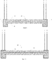
- the construction module comprises a floor formed by a concrete slab 41 entirely cast in the frame formed by the beams 4 of the base of the module, the two long beams of which are G-beams 20, so that the upper surface concrete 41 is flush with the fins 21 of the beam, that is to say at the same level, and whose lower face 42 rests on the flanges 24 of the G-beams 20.
- the hollow interior of the beams 20 is completely filled with concrete.
- the concrete slab is raised relative to the base of the module here defined in particular by the flange 22 of the beams. This elevation makes it possible, for example, to provide a crawl space and/or to provide a passage for electrical cables or water pipes.
- a wooden formwork between the flanges 24 can for example be used to pour the level concrete slab.
- the concrete slab 50 may alternatively comprise a prefabricated concrete slab (pre-slab) 51 resting on the edge 24 of the beams with the G profile 20 of the base, without abutting against the web 23 of the beams, and a concrete 52, poured over the entire surface of the pre-slab 51 and to the inside of the beams 20 of the base.
- pre-slab prefabricated concrete slab
- the poured concrete makes it possible to fix, in the mass, the pre-slab to the whole of the frame. He also allows the concrete slab to be stronger than if the module slab was made up of a pre-slab only. This configuration, without deteriorating the quality of the module, makes it possible to reduce the costs linked to the manufacture of the concrete slab.
- the pre-slab also plays the role of formwork for pouring the concrete, which simplifies the implementation of the slab manufacturing step.
- the pre-slab can consist of one element or of several elements, each element covering for example the width of the base and part of its length. The advantage of using several pre-slab elements is to have parts that are less heavy and bulky to handle.
- the concrete slab of the module can also be reinforced using reinforcement according to methods well known to those skilled in the art in order to further reinforce the solidity of the module and to increase the longevity of the concrete slab, and therefore of the module.
- the reinforcements can be housed in the pre-slab and/or in the poured concrete.
- the slab is intended to receive all the interior finishes of the floor of the module, e.g. tiling, parquet, smooth concrete, etc.
- the concrete slab can also incorporate various devices, e.g. an underfloor heating system.
- various devices e.g. an underfloor heating system.
- securing sockets 61 are inserted into the concrete slab and positioned so that the sockets can be secured, for example by means of a strap or cable 62, to the metal framework, preferably at the four corners 3 of the sky of the framework.
- These securing sleeves are used to optimize the lifting of the modules by distributing the stresses linked to the weight of the concrete slab in the metal frame.
- a space is arranged in the module to ensure, once the construction of the module is complete, access to said sockets.
- sockets are provided, but it is possible, depending on the configuration of the module, to provide one or more, depending in particular on the internal configuration of the module (partitions, load distribution, etc.) or its weight.
- the securing sleeves are preferably cast in concrete, to be completely integral with the slab.
- the foundations of the module are complete.
- the module can then be dressed with one or more side walls and equipped with a whole series of elements and equipment according to its final design.
- the module of the invention is only one element among others in a more complex modular construction.
- the position of the module within the construction is determined in advance during the design phase of the construction project, involving in particular, for example, an architect.
- a modular construction 70 (whose roof/terrace is not shown) consists of the horizontal juxtaposition of two modules 71 and 73 on which is placed, perpendicularly, a third module 73, partially covering the modules 71 and 72. together form, for example, a "duplex" type dwelling of about forty square meters and is equipped like a traditional studio, with, for example, a living space comprising a kitchen area and a living room and bathrooms as well as a bedroom on the 'stage. The whole rests on a foundation made before the arrival of the modules on site.
- modules 71 and 72 on the ground floor are juxtaposed by their long side.
- Each module on the ground floor therefore comprises three exterior walls and a large open wall allowing communication between the two modules 71 and 72.
- Module 73 on the floor comprises 4 exterior walls, the two walls of which are in the length are shortened to provide a balcony 79.
- An exterior wall 78 of module 72 is composed of a structure made of a rigid material, here wood.
- This wooden structure typically comprises a succession of vertical beams arranged at regular intervals between the high and low horizontal metal beams of the frame of the box and possibly horizontal lintels.
- the wooden structure serves as a support for, from the inside out, an interior finishing facing, a counter-battening, fireproof elements, a layer of insulation, a vapor barrier, a rain barrier, a exterior counter lathing and finally an exterior facing.
- the exterior wall 74 of the module 71 is equipped with a bay window 75, the frame of which is housed in the wooden structure of said wall, to allow entry and exit from the modular construction 70.
- the wall 74 is also equipped with a second window 76.
- Each module is also made up of a ceiling (not shown here) sandwiched between the metal beams defining the top of the frame.
- This ceiling to be differentiated from the roof of the module, allows for example to accommodate the lights and/or part of the electrical connection cables.
- a ceiling can be simply decorative like a false ceiling or include insulation.
- the upper module slab 73 represents the main separation between the two levels. Module 73 being the last of the construction in height, a roof 77 is installed there.
- the modules are mechanically fixed together, at least at the corners, using metal plates.
- These flats have features that facilitate crane operation (upper flats), truck mounting (lower flats) and mechanical assembly (by bolts).
- bolts passed through the holes provided in the G-profile. Fluid passages can also be provided in the lower part of the G-profiles .
- the three modules are assembled airtight and watertight. To do this, the connections to the common junctions of the two modules are made on site. “Connection” means the installation of a watertight and fireproof joint between the junctions and the extension of the exterior cladding.
- the means for connecting the modules also comprise sound absorption means and in particular a material which absorbs vibrations and sounds capable of being propagated via the metal frame of the module.
- the acoustic absorber or insulator is preferably associated with the fixing elements.
- the insulating absorber is of the type plate elastomer (natural rubber, synthetic rubber or a mixture of both).
- the module 73 and the part of the modules 71 and 72 not covered by the slab of the module 73 comprise a flat roof 77, of the warm roof type with a finish in bituminous rolls or EPDM tarpaulin, well known to those skilled in the art.
- the lower roof, installed on the sky of modules 71 and 72 can also be a terrace. In any case, this comes to ensure the tightness of the modular construction.
- the flat roof can be placed in the factory, and the sealing at the roof level between the modules adjusted on site or, the entire roof can be placed after assembling the modules on site.
- the module 73 As the module 73 is assembled vertically from the modules 71 and 72, there is provided a hopper in the ceiling of the lower module and at the corresponding place in the slab of the upper module, in order to allow the installation of a staircase.
- the elevator shafts, stairwells and car parks can be made on site, during foundations and/or after assembly of the modules.
- each module is transported by truck.
- the modules are dimensioned so as to be able to be transported by truck, possibly two by two, that is to say that their cumulative dimensions do not exceed the standards in force relating to the transport of goods.
- the loading and unloading of the modules on the truck can be done using a crane or an appropriate vehicle (e.g. a forklift).
- a crane or an appropriate vehicle e.g. a forklift
- these are craned using four attachment points, which are the four upper corners of the module.
- Craning at 4 gripping points can be facilitated by securing sockets in the concrete slab which, strapped to the metal frame, make it possible to distribute the load linked to the substantial weight of a concrete slab. This therefore makes it possible to avoid the six-point crane traditionally used in modular construction and de facto, to facilitate the movement of the modules and to reduce the associated costs by reducing the handling time.
- the four-point crane coupled with the use of anchor sleeves for the concrete slab, secures the installation of the modules.
- the number of sockets used, and the number of corners connected to the sockets can depend on the interior layout of the module which allows or not to tension the straps between the sockets and the corners.
- the position of one or more securing sleeves can be chosen according to these constraints.
- the modules are then connected together to ensure their cohesion and their airtightness and watertightness (joints of facing, roof, etc.) as well as to ensure their fireproof character.
- Aesthetic finishes such as the construction of a terrace, the facing of the foundations, the installation of an exterior staircase or the installation of a green roof are also carried out on site.
- the finished construction corresponds to the standards of conventional construction, from the point of view of the quality of materials as well as energy performance. Since most of the modules were built in the factory, the ecological impact is more limited and future deconstruction is easier. The construction could also be faster than a traditional construction. Indeed, the construction of the modules in the factory is not subject to the vagaries of the weather, does not require the coordination on site of several trades, and allows the optimization of all the logistical flows (single point of delivery of materials, storage on site, etc.) It is thus possible to save several months compared to traditional construction.
Landscapes
- Engineering & Computer Science (AREA)
- Architecture (AREA)
- Physics & Mathematics (AREA)
- Electromagnetism (AREA)
- Civil Engineering (AREA)
- Structural Engineering (AREA)
- Conveying And Assembling Of Building Elements In Situ (AREA)
- Rod-Shaped Construction Members (AREA)
Applications Claiming Priority (1)
| Application Number | Priority Date | Filing Date | Title |
|---|---|---|---|
| BE20205682A BE1028666B1 (fr) | 2020-10-01 | 2020-10-01 | Module constructif tridimensionnel préfabriqué |
Publications (1)
| Publication Number | Publication Date |
|---|---|
| EP3978697A1 true EP3978697A1 (de) | 2022-04-06 |
Family
ID=72840263
Family Applications (1)
| Application Number | Title | Priority Date | Filing Date |
|---|---|---|---|
| EP21200406.3A Withdrawn EP3978697A1 (de) | 2020-10-01 | 2021-10-01 | Vorgefertigtes 3d-baumodul |
Country Status (2)
| Country | Link |
|---|---|
| EP (1) | EP3978697A1 (de) |
| BE (1) | BE1028666B1 (de) |
Cited By (2)
| Publication number | Priority date | Publication date | Assignee | Title |
|---|---|---|---|---|
| US12091872B2 (en) | 2021-05-20 | 2024-09-17 | Sano Development Limited | Hybrid building system, building and method |
| GB2638400A (en) * | 2024-02-20 | 2025-08-27 | Sano Development Ltd | Modular building assembly |
Citations (6)
| Publication number | Priority date | Publication date | Assignee | Title |
|---|---|---|---|---|
| US4443992A (en) * | 1980-10-13 | 1984-04-24 | Mordechai Shechter | Method of prefabricated construction, and building structure constructed in accordance with such method |
| WO2002060614A1 (en) * | 2001-01-31 | 2002-08-08 | Innowork Oy | A method for manufacturing box girder, a box girder and a constructional part therefor |
| US20060168901A1 (en) * | 2002-12-03 | 2006-08-03 | John Window | Vertical alignment and levelling of modular building units |
| US20110162320A1 (en) * | 2003-06-23 | 2011-07-07 | Smorgon Steel Litesteel Products Pty Ltd | Beam |
| US20160222649A1 (en) * | 2015-01-29 | 2016-08-04 | Urbantainer Co., Ltd. | Container module for construction having fireproof floor slab and structure including the same |
| JP2017166123A (ja) * | 2016-03-14 | 2017-09-21 | 新日鐵住金株式会社 | 鉄骨梁および柱梁接合構造 |
-
2020
- 2020-10-01 BE BE20205682A patent/BE1028666B1/fr active IP Right Grant
-
2021
- 2021-10-01 EP EP21200406.3A patent/EP3978697A1/de not_active Withdrawn
Patent Citations (6)
| Publication number | Priority date | Publication date | Assignee | Title |
|---|---|---|---|---|
| US4443992A (en) * | 1980-10-13 | 1984-04-24 | Mordechai Shechter | Method of prefabricated construction, and building structure constructed in accordance with such method |
| WO2002060614A1 (en) * | 2001-01-31 | 2002-08-08 | Innowork Oy | A method for manufacturing box girder, a box girder and a constructional part therefor |
| US20060168901A1 (en) * | 2002-12-03 | 2006-08-03 | John Window | Vertical alignment and levelling of modular building units |
| US20110162320A1 (en) * | 2003-06-23 | 2011-07-07 | Smorgon Steel Litesteel Products Pty Ltd | Beam |
| US20160222649A1 (en) * | 2015-01-29 | 2016-08-04 | Urbantainer Co., Ltd. | Container module for construction having fireproof floor slab and structure including the same |
| JP2017166123A (ja) * | 2016-03-14 | 2017-09-21 | 新日鐵住金株式会社 | 鉄骨梁および柱梁接合構造 |
Cited By (5)
| Publication number | Priority date | Publication date | Assignee | Title |
|---|---|---|---|---|
| US12091872B2 (en) | 2021-05-20 | 2024-09-17 | Sano Development Limited | Hybrid building system, building and method |
| US12180731B2 (en) | 2021-05-20 | 2024-12-31 | Sano Development Limited | Hybrid building system, building and method |
| US12180730B2 (en) | 2021-05-20 | 2024-12-31 | Sano Development Limited | Hybrid building system, building and method |
| US12203281B2 (en) | 2021-05-20 | 2025-01-21 | Sano Development Limited | Hybrid building system, building and method |
| GB2638400A (en) * | 2024-02-20 | 2025-08-27 | Sano Development Ltd | Modular building assembly |
Also Published As
| Publication number | Publication date |
|---|---|
| BE1028666A1 (fr) | 2022-04-26 |
| BE1028666B1 (fr) | 2022-05-02 |
Similar Documents
| Publication | Publication Date | Title |
|---|---|---|
| EP0160155B1 (de) | Vorgefertigter Bauelementensatz | |
| FR2931496A1 (fr) | Panneau monobloc prefabrique multicouche pour la realisation des parois d'une habitation, procede de fabrication d'un tel panneau et habitation equipee de tels panneaux | |
| BE1028666B1 (fr) | Module constructif tridimensionnel préfabriqué | |
| FR2950638A1 (fr) | Systeme constructif pour batiments | |
| US5090884A (en) | Apparatus for manufacturing hollow concrete structures | |
| BE509590A (de) | ||
| CN101466905B (zh) | 用于建筑物构造的预制墙板和用于制造这种墙板的方法 | |
| FR2610022A1 (fr) | Systeme constructif, par cadres bois modulaires, formant structures, et leur procede de montage | |
| EP0081496B1 (de) | Industrialisiertes gebäudesystem aus metall, mit mehreren stockwerken und in der werkstatt hergestellten elementen | |
| FR2866040A1 (fr) | Elements prefabriques verticaux modulaires pour l'elevation de murs d'habitation isoles avec finitions ainsi que leur procede de fabrication | |
| WO2016034729A1 (fr) | Procede de construction immobiliere et panneau pour construction immobiliere mettant en oeuvre un tel procede | |
| FR3003878A3 (fr) | Construction comportant des cloisons amovibles | |
| FR3152280A1 (fr) | Panneau de construction en materiau isolant | |
| FR2561280A1 (fr) | Modules monolithiques prefabriques destines a la construction de batiments et leur procede de fabrication | |
| FR2627791A1 (fr) | Systeme constructif de mur porteur en panneaux composites a ossature metallique | |
| FR2808295A1 (fr) | Elements modulaires fabriques industriellement a partir de materiaux extrudables pour la realisation et l'assemblage de coffrages perdus (destines aux murs et ouvrages en beton), de cloisons, de mobiliers urbains et domestiques | |
| EP1365080A1 (de) | Herstellungsverfahren für eine tragende Wand aus Stahlbeton | |
| FR3093745A1 (fr) | Dispositif de fixation d’un panneau préfabriqué à une dalle | |
| BE1023535B1 (nl) | Constructiemodule en modulair bouwsysteem omvattende één of meerdere van dergelijke constructiemodules | |
| EP4411084A1 (de) | Vorgefertigtes modul für einen modularen raum | |
| FR2584754A1 (fr) | Les modules multicadres ou chassis colles a usage de locaux d'habitation et de mobilier | |
| WO2024149433A1 (ru) | Способ быстрого строительства здания ищенко | |
| FR2638182A1 (fr) | Construction prefabriquee modulaire a usage d'habitation | |
| FR2766852A1 (fr) | Procede industriel de fabrication de gros oeuvre de batiments d'habitation et batiments correspondants | |
| EA045584B1 (ru) | Способ быстрого строительства здания ищенко |
Legal Events
| Date | Code | Title | Description |
|---|---|---|---|
| PUAI | Public reference made under article 153(3) epc to a published international application that has entered the european phase |
Free format text: ORIGINAL CODE: 0009012 |
|
| STAA | Information on the status of an ep patent application or granted ep patent |
Free format text: STATUS: THE APPLICATION HAS BEEN PUBLISHED |
|
| AK | Designated contracting states |
Kind code of ref document: A1 Designated state(s): AL AT BE BG CH CY CZ DE DK EE ES FI FR GB GR HR HU IE IS IT LI LT LU LV MC MK MT NL NO PL PT RO RS SE SI SK SM TR |
|
| STAA | Information on the status of an ep patent application or granted ep patent |
Free format text: STATUS: REQUEST FOR EXAMINATION WAS MADE |
|
| 17P | Request for examination filed |
Effective date: 20220929 |
|
| RBV | Designated contracting states (corrected) |
Designated state(s): AL AT BE BG CH CY CZ DE DK EE ES FI FR GB GR HR HU IE IS IT LI LT LU LV MC MK MT NL NO PL PT RO RS SE SI SK SM TR |
|
| P01 | Opt-out of the competence of the unified patent court (upc) registered |
Effective date: 20230525 |
|
| STAA | Information on the status of an ep patent application or granted ep patent |
Free format text: STATUS: EXAMINATION IS IN PROGRESS |
|
| 17Q | First examination report despatched |
Effective date: 20240124 |
|
| STAA | Information on the status of an ep patent application or granted ep patent |
Free format text: STATUS: THE APPLICATION HAS BEEN WITHDRAWN |
|
| 18W | Application withdrawn |
Effective date: 20240508 |