EP4411084A1 - Vorgefertigtes modul für einen modularen raum - Google Patents
Vorgefertigtes modul für einen modularen raum Download PDFInfo
- Publication number
- EP4411084A1 EP4411084A1 EP24156074.7A EP24156074A EP4411084A1 EP 4411084 A1 EP4411084 A1 EP 4411084A1 EP 24156074 A EP24156074 A EP 24156074A EP 4411084 A1 EP4411084 A1 EP 4411084A1
- Authority
- EP
- European Patent Office
- Prior art keywords
- module
- slab
- modules
- gable walls
- gable
- Prior art date
- Legal status (The legal status is an assumption and is not a legal conclusion. Google has not performed a legal analysis and makes no representation as to the accuracy of the status listed.)
- Pending
Links
- 238000005192 partition Methods 0.000 claims description 43
- 239000002023 wood Substances 0.000 claims description 25
- 238000009423 ventilation Methods 0.000 description 13
- 238000004519 manufacturing process Methods 0.000 description 12
- 238000010276 construction Methods 0.000 description 11
- 238000000034 method Methods 0.000 description 7
- 238000005253 cladding Methods 0.000 description 6
- 238000009434 installation Methods 0.000 description 6
- 229910052782 aluminium Inorganic materials 0.000 description 4
- XAGFODPZIPBFFR-UHFFFAOYSA-N aluminium Chemical compound [Al] XAGFODPZIPBFFR-UHFFFAOYSA-N 0.000 description 4
- 238000009417 prefabrication Methods 0.000 description 4
- 229910052799 carbon Inorganic materials 0.000 description 3
- 239000011094 fiberboard Substances 0.000 description 3
- 239000011491 glass wool Substances 0.000 description 3
- 239000011490 mineral wool Substances 0.000 description 3
- 239000005871 repellent Substances 0.000 description 3
- 241001639412 Verres Species 0.000 description 2
- 238000010521 absorption reaction Methods 0.000 description 2
- 239000004411 aluminium Substances 0.000 description 2
- 230000004888 barrier function Effects 0.000 description 2
- 238000000605 extraction Methods 0.000 description 2
- 239000000835 fiber Substances 0.000 description 2
- 238000010438 heat treatment Methods 0.000 description 2
- 238000009413 insulation Methods 0.000 description 2
- 238000002955 isolation Methods 0.000 description 2
- 239000000203 mixture Substances 0.000 description 2
- 238000010422 painting Methods 0.000 description 2
- 230000036961 partial effect Effects 0.000 description 2
- 239000000779 smoke Substances 0.000 description 2
- OKTJSMMVPCPJKN-UHFFFAOYSA-N Carbon Chemical compound [C] OKTJSMMVPCPJKN-UHFFFAOYSA-N 0.000 description 1
- 241000287107 Passer Species 0.000 description 1
- 229910000831 Steel Inorganic materials 0.000 description 1
- 230000006978 adaptation Effects 0.000 description 1
- 238000004378 air conditioning Methods 0.000 description 1
- 230000003466 anti-cipated effect Effects 0.000 description 1
- 230000000712 assembly Effects 0.000 description 1
- 238000000429 assembly Methods 0.000 description 1
- 230000002860 competitive effect Effects 0.000 description 1
- 230000007547 defect Effects 0.000 description 1
- 238000009826 distribution Methods 0.000 description 1
- 230000004907 flux Effects 0.000 description 1
- 238000005399 mechanical ventilation Methods 0.000 description 1
- 229910052751 metal Inorganic materials 0.000 description 1
- 239000002184 metal Substances 0.000 description 1
- 238000005457 optimization Methods 0.000 description 1
- 239000011505 plaster Substances 0.000 description 1
- 230000008569 process Effects 0.000 description 1
- 238000003908 quality control method Methods 0.000 description 1
- 238000011084 recovery Methods 0.000 description 1
- 230000009467 reduction Effects 0.000 description 1
- 230000001105 regulatory effect Effects 0.000 description 1
- 239000011435 rock Substances 0.000 description 1
- 239000000523 sample Substances 0.000 description 1
- 238000000638 solvent extraction Methods 0.000 description 1
- 230000000087 stabilizing effect Effects 0.000 description 1
- 239000010959 steel Substances 0.000 description 1
- 235000013311 vegetables Nutrition 0.000 description 1
- 238000004078 waterproofing Methods 0.000 description 1
Images


Classifications
-
- E—FIXED CONSTRUCTIONS
- E04—BUILDING
- E04B—GENERAL BUILDING CONSTRUCTIONS; WALLS, e.g. PARTITIONS; ROOFS; FLOORS; CEILINGS; INSULATION OR OTHER PROTECTION OF BUILDINGS
- E04B1/00—Constructions in general; Structures which are not restricted either to walls, e.g. partitions, or floors or ceilings or roofs
- E04B1/348—Structures composed of units comprising at least considerable parts of two sides of a room, e.g. box-like or cell-like units closed or in skeleton form
- E04B1/34815—Elements not integrated in a skeleton
- E04B1/34838—Elements not integrated in a skeleton the supporting structure consisting of wood
-
- E—FIXED CONSTRUCTIONS
- E04—BUILDING
- E04B—GENERAL BUILDING CONSTRUCTIONS; WALLS, e.g. PARTITIONS; ROOFS; FLOORS; CEILINGS; INSULATION OR OTHER PROTECTION OF BUILDINGS
- E04B1/00—Constructions in general; Structures which are not restricted either to walls, e.g. partitions, or floors or ceilings or roofs
- E04B1/343—Structures characterised by movable, separable, or collapsible parts, e.g. for transport
- E04B1/34336—Structures movable as a whole, e.g. mobile home structures
- E04B1/34352—Base structures or supporting means therefor
-
- E—FIXED CONSTRUCTIONS
- E04—BUILDING
- E04B—GENERAL BUILDING CONSTRUCTIONS; WALLS, e.g. PARTITIONS; ROOFS; FLOORS; CEILINGS; INSULATION OR OTHER PROTECTION OF BUILDINGS
- E04B1/00—Constructions in general; Structures which are not restricted either to walls, e.g. partitions, or floors or ceilings or roofs
- E04B1/62—Insulation or other protection; Elements or use of specified material therefor
- E04B1/92—Protection against other undesired influences or dangers
- E04B1/94—Protection against other undesired influences or dangers against fire
- E04B1/941—Building elements specially adapted therefor
- E04B1/942—Building elements specially adapted therefor slab-shaped
Definitions
- the present application relates to a prefabricated module for a room, a floor assembly of at least two such modules, a modular room comprising at least two such modules, and a building comprising such a floor assembly and/or such a modular room.
- Buildings can be constructed from modules prefabricated in a factory and assembled on site. For example, rooms, such as classrooms, can be built by assembling prefabricated modules together.
- the rooms of these buildings are assembled from several identical standardized modules.
- the modules are stacked on top of each other to create multiple floors of the building.
- Each floor includes several rooms formed from respective assemblies of prefabricated modules. All the rooms have similar dimensions to each other.
- the architecture of each floor of the building, particularly the layout of rooms and corridors on each floor, is identical. Such a building is easy to assemble, and the associated structural constraints can be easily anticipated and respected.
- An objective of the present application is to propose a prefabricated module which is economically competitive, that is to say which has a limited manufacturing cost and which is easy to assemble.
- An objective of the present application is to propose a prefabricated module making it possible to improve the architectural flexibility of a room or a building integrating the module.
- the present application concerns a floor assembly of a first prefabricated module according to the first aspect and a second prefabricated module according to the first aspect, in which the second module forms an upper module which is assembled above of the first module which forms a lower module, the slab of the upper module being in contact with at least part of each of the gable walls of the lower module.
- the two gable walls of the upper module are respectively aligned in the height direction of the modules with the two gable walls of the lower module.
- the two gable walls of the upper module can be aligned respectively with the two gable walls of the lower module over the entire depth P of the module or only over part of the depth P of the module.
- the partitions of the upper module are not necessarily aligned with the partitions of the lower module. This makes it possible to adapt the interior volume of the modules according to needs.
- the present application relates to a modular room, in particular a classroom, comprising at least two prefabricated modules according to the first aspect, in which the modules of the modular room are assembled adjacently in the depth direction of the modules, so that the two gable walls of a module respectively extend the two gable walls of an adjacent module to form two substantially continuous room walls extending in the depth direction of the modules.
- the present application concerns a building comprising at least one of a floor assembly according to the second aspect and a modular room according to the third aspect.
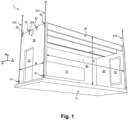
- the two gable walls 30 and the slab 10 together form a supporting structure configured to take up loads exerted on the module 1 by an upper module configured to be assembled with the module 1 by being placed above the module 1 and in contact with at least a part of each of the two gable walls 30 of module 1.
- Each gable wall 30 extends mainly in the depth direction P and in a height direction H.
- the slab 10 and the ceiling 20 each extend mainly in a width direction L and in the depth direction P.
- the directions of width L, height H and depth P are perpendicular to each other.
- the terms lower and upper, respectively below and above, are used with reference to the height direction H, the slab 10 being located below the ceiling 20, that is to say -say in a lower position in relation to ceiling 20.
- the two gable walls 30 have substantially identical dimensions, a dimension of a gable wall 30 in the height direction H corresponding to the height h of module 1, and a dimension of a gable wall 30 in the depth direction P corresponding at a depth p of module 1.
- the two gable walls 30 are separated from each other in the direction of width L by a distance corresponding to the width l of module 1.
- the terms exterior and interior are used with reference to the width direction L, an interior element being located closer to an axis equidistant from the two gable walls 30 than an exterior element.
- the slab 10, the ceiling 20 and the two gable walls 30 delimit between them an interior volume of the module 1.
- the terms front and rear are used with reference to the depth direction P.
- the module 1 described above can be manufactured in the factory, the modules 1 being subsequently assembled on site to form rooms and/or buildings.
- Module 1 manufacturing can take into account the handling requirements of Module 1 and on-site assembly. This method of manufacturing and assembly makes it possible to reduce construction site nuisances during the manufacture of module 1, to improve factory quality control, to increase the speed of module 1 manufacturing and building assembly, and to optimize construction costs through standardization and to the prefabrication of modules 1.
- the factory prefabricated module 1 can be easily loaded onto a truck, transported to the construction site and then directly installed at the site assembly location, so as to minimize on-site intervention. Furthermore, when installing the module on the site, modular manufacturing makes it possible to optimize the design time and the construction phase of the site, to reduce the arduousness of the work, the site nuisance, and the carbon footprint. .
- the supporting structure forms a supporting bracing.
- the slab 10, which forms the floor of module 1, and the gable walls 30, are load-bearing and together form the load-bearing bracing, the slab 10 and the gable walls 30 playing a structural role.
- the ceiling 20 of module 1 is non-load-bearing and does not form part of the load-bearing bracing once module 1 is assembled, that is to say it does not play a structural role.
- the weight of the upper module and the loads acting on the upper module are therefore taken up by the gable walls 30 and the slab 10.
- the slab 10 has sufficient thickness and mechanical strength to recover the loads of the upper module and rebroadcast them to the gable walls 30 of module 1.
- the slab 10 may comprise a multilayer wood panel 302, for example a laminated veneer lumber panel (LVL), or a cross laminated wood panel (CLT). , or even a “box” type floor.
- the multilayer wood panel 302 forms the framework of slab 10, and makes it possible to meet current low-carbon construction requirements.
- the multilayer wood panel 302 of the slab 10 may have a thickness of between 100 mm and 300 mm, for example a thickness of between 130 mm and 240 mm, for example a thickness of between 140 mm and 200 mm.
- the slab 10 can be a slab 10 CLT 240 mm 7 ss DL, for example with an Nsi finish.
- the slab 10 has a dimension in the height direction H which is adapted to support the operating loads of the building, play the role of load-bearing bracing, support seismic constraints, etc.
- the slab 10 can be covered with a floor covering, for example a PVC linoleum type covering, where appropriate with an under-covering of medium density fiberboard (in English MDF, “Medium Density Fiberboard”) making it possible to correct any flatness defects.
- a floor covering for example a PVC linoleum type covering, where appropriate with an under-covering of medium density fiberboard (in English MDF, “Medium Density Fiberboard”) making it possible to correct any flatness defects.
- the two gable walls 30 of module 1 can each comprise a multi-layer wood panel 302, for example a laminated wood panel or a cross-laminated wood panel.
- the multi-layer wood panel 302 forms the framework of the gable walls 30, and makes it possible to meet current low-carbon construction requirements.
- the association between the gable walls 30 each comprising a multi-layer wooden panel 302 and a slab 10 comprising a multi-layer wooden panel 302 makes it possible to provide the module 1 with the structural strength adapted to form the supporting structure.
- the multilayer wooden panel 302 of each gable wall 30 may have a thickness of between 100 mm and 300 mm, for example a thickness of between 130 mm and 240 mm, for example a thickness of between 140 mm and 200 mm.
- the multilayer wood panel 302 of the gable wall 30 may be a wood frame wall panel (MOB) having a thickness of 140 mm.
- At least one of the two gable walls 30 of module 1 can be configured to form a corridor wall of a building comprising module 1, said gable wall 30 of the corridor being separate from the circulation. At least one of the two gable walls 30 of module 1 can be configured to form a facade wall of a building comprising module 1, said gable facade wall 30 delimiting a space exterior to a building made from module 1
- one of the two gable walls 30 of module 1 can be a gable wall 30 of a corridor, while the other of the two gable walls 30 of module 1 can be a gable wall 30 of a facade.
- the gable wall 30 comprises an interior face and an exterior face opposite the interior face.
- the interior face of the gable wall 30 contributes to delimiting the interior volume of module 1, while the exterior face of the gable wall 30 can contribute to forming the facade in the case of a facade gable wall 30, or contribute to delimiting the corridor in the case of a gable wall 30 of a corridor.
- Each gable wall 30 comprises a front edge and a rear edge opposite the front edge.
- the front edge and the rear edge each form a flat surface extending in the direction of height H and in the width direction L of module 1 and connecting the interior face and the exterior face of the gable wall 30.
- At least one of the two gable walls 30 may include at least one opening 31, 32, adapted to receive a door or a window.
- the dimensions of the opening 31, 32 are adjustable.
- One of the two gable walls 30, for example the gable wall 30 of a corridor, may include at least one opening adapted to receive a door.
- the other of the two gable walls 30, for example the gable wall 30 of the facade may comprise at least one opening adapted to receive a window, for example may comprise one or two openings, each opening being adapted to receive a window.
- the door can be a landing door allowing an acoustic reduction of around 37 dB, with a simple lock.
- the window may include a roller shutter with electrical control by radio switch and group remote control.
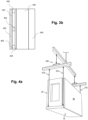
- FIG. 3a illustrates by way of non-limiting example a sectional view of a stack of layers forming a gable wall 30 of a module 1.
- each gable wall 30 may further comprise an interior facing layer 301.
- the interior facing layer 301 is arranged inside all the other layers of the gable wall 30 and is visible from the interior volume of module 1.
- the panel of multilayer wood 302 can be juxtaposed with the interior facing layer 301.
- the interior facing layer 301 can be made of plaster, for example be a BA18 plasterboard type layer.
- Each gable wall 30 may further comprise at least one insulating layer 303.
- the insulating layer 303 may be a layer of compact rock wool or glass wool.
- the insulating layer 303 may have a thickness of between 100 mm and 200 mm, for example a thickness of 140 mm.
- An insulating layer 303 can be placed inside the multi-layer wood panel 302 of the gable wall 30 and/or an insulating layer 303 can be placed outside the multi-layer wood panel 302 of the gable wall 30.
- Each gable wall 30 may further comprise a rainproof layer 304.
- the rainproof layer 304 can be placed outside the multilayer wood panel 302 and, where appropriate, outside the insulating layer 303 of the gable wall. 30.
- At least one of the gable walls 30, in particular the facade gable wall 30, may further comprise a layer of facade cladding 305.
- the layer of facade cladding 305 can be placed outside all the other layers of the gable wall 30 and can be visible from the outside of module 1.
- the facade covering layer 305 forms an exterior cladding forming the facade.
- the facade covering layer 305 can be chosen depending on the aesthetics desired for the facade, external constraints and/or the height of the building.
- the facade cladding layer 305 may include compact laminated panel facing.
- At least one of the gable walls 30, in particular the gable wall 30 of the facade, may further comprise joists arranged inside and in contact with the layer of facade covering 305.
- At least one of the gable walls 30, in particular the gable wall 30 of the facade may further comprise an exterior covering 306 which may be a ribbed steel sheet or a facing complex adapted to be attached and fixed to the layer of facade covering 305, outside the facade covering layer 305.
- an exterior covering 306 which may be a ribbed steel sheet or a facing complex adapted to be attached and fixed to the layer of facade covering 305, outside the facade covering layer 305.
- the multilayer wood panel 302, the rainproof layer 304 and the facade covering layer 305 can be arranged successively from the inside of the module 1 towards the outside of the module 1, for example be juxtaposed successively with each other from inside module 1 towards the outside of module 1.
- the two gable walls 30 of module 1 can each comprise a facade covering comprising a facing layer 401, a first water-repellent layer 402, a second water-repellent layer 404, battens 403 positioned between the two water-repellent layers 402 and 404 and allowing circulation air between these two layers.
- the two gable walls 30 also include an insulating layer 405 then a cross-laminated wood panel.
- FIG. 2 illustrates by way of non-limiting example a sectional view of a stack of layers forming a ceiling 20 of a module 1.
- the prefabricated module 1 may further comprise at least one partition 40 extending substantially perpendicular to the slab 10 and the ceiling 20 in a direction of module width L so as to connect the two gable walls 30.
- the partition 40 is not load-bearing, but participates in the bracing of module 1, as well as in the overall bracing of all modules 1 once assembled. Thus, when two modules are placed one above the other, it is not necessary to align the partitions of the upper module with those of the lower module. It is thus possible to produce modules in which the partitions are more or less distant from each other so as to adapt the interior volume of the modules to the needs.
- the partition 40 further connects the slab 10 and the ceiling 20.
- the partition 40 extends mainly in the height direction H and in the width direction L.
- a dimension of the partition 40 in the width direction L of the module 1 corresponds to the width l of module 1.
- a module 1 may comprise a front partition 40 connecting the front edges of the two gable walls 30 of module 1 to each other, and/or a rear partition 40 connecting the rear edges of the two gable walls 30 of module 1 to each other.
- the module 1 comprises a front partition 40 and a rear partition 40
- the front partition 40 and the rear partition 40 extend opposite each other and at a distance from one another. the other in the depth direction P.
- a partition 40 may include an opening 31, 32 adapted to receive a door.
- the door received in the opening of the partition 40 can connect two adjacent rooms, which allows better fire safety.
- the partition 40 may have acoustic, fire resistance and/or flame resistance properties so that a junction of two modules 1 at the level of two respective partitions 40 of the two modules 1 forms a flame arrestor partition 40 and acoustics.
- the gable walls 30 and/or the slab 10 can be fire-rated elements for 30 minutes or more, that is to say they are adapted to prevent the spread of a fire for at least 30 minutes by not allowing a given heat to pass during this time.
- the gable walls 30 and/or the slab 10 are thus classified REI 30 at least, that is to say that they have a load-bearing function and are fire-rated for 30 minutes or more.
- the main structure of the building is thus stable against fire.
- the door can be a 30 min or more flame protection door, that is to say it is adapted to prevent flames and smoke from passing through for at least half an hour.
- the presence of standardized equipment elements and/or system elements ensuring compliance with a standard in the prefabricated module 1 makes it possible to facilitate the assembly of modules 1 on site and to reduce construction costs and exploitation.
- the room constructed by the assembly of modules 1 makes it possible to provide one or more standardized interior services and/or presents one or more standardized interior equipment and/or complies with one or more regulatory standard requirements.
- Module 1 may further comprise a lifting ring 51 attached and removably fixed to the slab 10, and/or a lifting bracket 52 attached and removably fixed to one of the gable walls 30.
- the lifting ring 51 and/or the lifting fitting 52 form a lifting system adapted to allow the handling of the module 1 by a lifting device adapted to control a movement of a lifting rod 510.
- a lifting device adapted to control a movement of a lifting rod 510.
- the lifting device may be a construction crane. As illustrated by way of non-limiting example in figure 4a , the lifting device may include an adjustable spreader 520, the lifting rod 510 being adapted to be fixed to said spreader 520.
- the use of a spreader 520 makes it possible to improve the balancing of the modules 1 during their handling.
- the lifting rod 510 is adapted to be inserted through the lifting bracket 52.
- the lifting rod 510 includes a first end attached to the lifting apparatus, and a second end opposite the first end.
- the second end of the lifting rod 510 forms a lifting hook adapted to hook the lifting ring 51 when the lifting rod 510 is inserted through the lifting fitting 52.
- the lifting bracket 52 can be attached and removably fixed to the exterior face of the gable wall 30, in particular at an upper end of the gable wall 30, a height position of the lifting bracket 52 corresponding for example substantially at a position in height of the ceiling 20.
- the lifting fitting 52 may comprise a through hole extending substantially in the height direction H of the module 1, the lifting rod 510 being adapted to be inserted through the through hole of the lifting fitting 52.
- the lifting fitting 52 may be a funnel fitting.
- the lifting ring 51 can be configured to be attached and removably fixed to an upper face of the slab 10, outside the gable wall 30, so as to extend upwards in the height direction H of module 1.
- the lifting fitting 52 can be arranged opposite the lifting ring 51 in the height direction H of the module 1, so that the lifting rod 510 extends substantially in the height direction H of module 1 when it is put in place for handling module 1.
- the slab 10 may comprise an overhang, in the form of a protrusion extending towards the outside of the module 1 beyond the gable wall 30, in the direction of width L of the module.
- the lifting ring 51 is configured to be attached and removably fixed to the overhang of the slab 10.
- Each module 1 may include two lifting rings 51 configured to be attached and removably fixed to the slab 10 of module 1 and two lifting fittings 52 configured to be attached and removably fixed to one of the gable walls 30 in view respectively of the two lifting rings 51 in the height direction H of the module 1.
- two lifting rods 510 can be used to lift and move the module 1 by one of the faces of the module 1, which makes it possible to improve the stability and handling balancing of module 1.
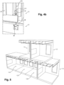
- each module 1 may include four lifting fittings 52, as illustrated by way of non-limiting example in figure 4a .
- Two lifting fittings 52 are configured to be attached and removably fixed to one of the two gable walls 30 of module 1 and two lifting fittings 52 are configured to be attached and removably fixed to the other of the two walls pinion 30 of module 1.
- Module 1 further comprises four lifting rings 51 configured to be attached and removably fixed on the slab 10, at the four corners of the slab 10, facing respectively the four lifting fittings 52 in the height direction H of module 1.
- four lifting rods 510 of the lifting device can be used to lift and move module 1 by the two gable walls 30 of module 1, which makes it possible to further improve stability and balancing the handling of module 1.
- At least two modules 1 as described above can be assembled in stages.
- the second module 1, 3 forms an upper module 3 which is assembled above the first module 1, 2 which forms a lower module 2.
- the slab 10 of the upper module 3 is in contact with at least part of each of the gable walls 30 of the lower module 2.
- the supporting structure formed by the two gable walls 30 and the slab 10 of the lower module 2 effectively takes up the loads exerted by the upper module 3.
- a floor assembly allows great flexibility in the arrangement of the upper module 3 above the lower module 2.
- the upper module 3 can have identical dimensions, in particular the depth P and the height H, or different from the dimensions of the lower module 2, which makes it possible to further improve architectural flexibility of floor assembly.
- the width L of the two modules is identical so as to be able to align the gable walls 30 of the lower module 2 with those of the upper module 3.
- the directions of height H, width L and depth P of the lower 2 and upper 3 modules can be identical, the two modules 2, 3 being superimposed one on the other with the same orientation for better stability of the assembly in stages and better load absorption by the supporting structure of the lower module 2.
- the lower module 2 and the upper module 3 can have an identical width l and a height h, and an identical or different depth p.
- FIG. 5 illustrates by way of non-limiting example a floor assembly of several lower modules 2 and several upper modules 3.
- the lower modules 2 illustrated in the figure 5 are intended to be placed on the ground so as to form the ground floor of the building and the upper modules 4 are intended to form the first floor of the building.
- a so-called “lower” module can be intended to form any floor n of the building, the so-called “upper” module being intended to form the floor n+1 of the building, the so-called “lower” module corresponding to a higher module compared to a module intended to form floor n-1 of the building.
- the two gable walls 30 of the upper module 3 are respectively aligned in the height direction H of the modules with the two gable walls 30 of the lower module 2.
- the upper module 3 is thus aligned with the lower module 2 in the width direction L of the modules 2, 3.
- the gable walls 30 of the upper module 3 are aligned two by two in the height direction H with the gable walls 30 of the lower module 2.
- the width l of the lower module 2 is identical to the width 3 of the upper module 3.
- the two gable walls 30 of the upper module 3 are aligned with each of the two gable walls 30 of the lower module 2.
- the lower modules 2 and the upper module 3 have different depths and the partitions of the lower module 2 are therefore not aligned with the partitions of the upper module 3.
- the upper module 3 is thus offset relative to the lower module 2 in the depth direction P of the modules 2, 3. Such shifting of the modules 2, 3 is made possible by the recovery of the loads by the gable walls 30 and the slab 10.
- the modules 2, 3 can be stacked on top of each other in a staggered manner, an upper module 3 being placed on a lower module 2, by aligning the gable walls of the modules upper 3 and lower 2 but without it being necessary to align the partitions 40 of the upper 3 and lower 2 modules.
- the slab 10 of the upper module 3 is placed partly on the ceiling 20 of the lower module 2, and partly on the ceiling 20 of a lower module adjacent to the lower module 2 in the depth direction P of the modules 2, 3.
- the slab 10 of the upper module 3 is thus in contact with the two gable walls 30 and a part of the ceiling 20 of the lower module 2.
- the upper module 3 may further comprise a connection rod 55 of the upper module 3 with the lower module 2
- the lower module 2 may comprise a connection fitting 56 of the lower module 2 with the upper module 3.
- connection bracket 56 can be attached and fixed to the exterior face of the gable wall 30 of the lower module 2, in particular at an upper end of the gable wall 30, a height position of the connection bracket 56 corresponding for example substantially at a position in height of the ceiling 20 of the lower module 2.
- the connection fitting 56 may comprise a through hole extending substantially in the height direction H of the lower module 2, the connection rod 55 being adapted to be inserted at through the through hole of the connection fitting 56.
- the connection fitting 56 may be a funnel fitting.
- the connection bracket 56 may correspond to the lifting bracket 52.
- connection rod 55 can be attached and fixed to a lower face of the slab 10 of the upper module 3, outside the gable wall 30, so as to extend downwards in the height direction H of the upper module 3 when the upper module 3 is stacked on the lower module 2.
- the connection rod 55 can be configured to extend on the opposite side of the lifting ring 51 relative to the slab 10 of the upper module 3.
- the connecting rod connection 55 can for example be an M30 threaded rod. A washer and a nut can be placed during the prefabrication of module 1 on the connection rod 55.
- connection rod 55 of the upper module 3 can be arranged facing the connection bracket 56 of the lower module 2 in the height direction H of the modules when the upper module 3 is stacked on the lower module 2, so that the connection rod 55 of the upper module 3 can be inserted into the through hole of the connection bracket 56 of the lower module 2.
- connection rods 55 can be attached and fixed to the four corners of the slab 10 of the upper module 3.
- connection fittings 56 can be attached and fixed two by two on the two gable walls 30 of the lower module 2, in view respectively of the four connection rods 55.
- the upper module 3 comprising the connection rods 55 can easily be placed on the lower module 2 comprising the connection fittings 56.
- connection rods of the upper module are placed in fittings of two different lower modules.
- a modular room in particular a classroom, can consist of a single module 1 as described above, said single module 1 comprising two partitions 40 as described above.
- the interior volume of module 1 corresponds to the volume of the modular room.
- a modular room in particular a classroom, may comprise at least two prefabricated modules 1, 4, 5, 6 as described above.
- the modules 1, 4, 5, 6 of the modular room are assembled adjacently in the depth direction P of the modules, such that the two gable walls 30 of a module 1, 4, 5, 6 respectively extend the two gable walls 30 of an adjacent module 1, 4, 5, 6 to form two substantially continuous room walls extending in the depth direction P of the modules.
- the height H, width L and depth P directions of all the modules 1, 4, 5, 6 of the modular room may be identical, the modules 1, 4, 5, 6 being juxtaposed with each other in the depth direction P of the modules.
- the modular room may comprise a front module 4 comprising a front partition 40, and a rear module 6 comprising a rear partition 40.
- the front partition 40 and the rear partition 40 are arranged opposite each other and at a distance from each other. other in the depth direction P of the modules.
- a distance between the front partition 40 and the rear partition 40 corresponds to a depth of the modular room.
- the two room walls each connect the front partition 40 of the front module 4 and the rear partition 40 of the rear module 6.
- the two room walls, all of the slabs 10 of modules 1, 4, 5, 6, all ceilings 20 of modules 1, 4, 5, 6, and the front and rear partitions 40 of the front module 4 and the rear module 6, together delimit a closed interior volume of the room.
- the modular room may include one or more intermediate modules 5 arranged between the front module 4 and the rear module 6.
- An intermediate module 5 does not include any partition 40, and thus forms a tunnel adapted to connect the front module 4 and the rear module 6 .
- There Figure 6 illustrates a non-limiting example of such an intermediate module 5.
- the figure 5 illustrates by way of non-limiting example a modular room comprising a front module 4, an intermediate module 5, and a rear module 6, the modules 4, 5, 6 being juxtaposed with each other in the depth direction P of the modules. so as to form the modular room.
- the front module 4, the intermediate module 5, and the rear module 6 illustrated in figure 5 are lower modules 2, but it is understood that an upper module 3 can also have a similar architecture comprising a front module 4, one or more intermediate modules 5, and a rear module 6.
- the table 41 can be attached and removably fixed to the front partition 40 of the front module 4.
- the gable wall 30 of the front of the front module 4 and the gable wall 30 of the front of the rear module 6 can each include an opening 32 adapted for receive a window.
- the gable wall 30 of the facade of the intermediate module 5 may include one or two openings adapted to each receive a window 32.
- the modular room can be a classroom, for example a room in a school, college or high school.
- the modular room can be a room in an establishment open to the public other than a school establishment.
- a building may include at least one of a floor assembly as described above and a modular room as described above.
- the building may be a school establishment.
- the building may be an establishment open to the public other than a school establishment.
- Such manufacturing of a building by prefabricated modules 1 is particularly suitable when the building includes rooms which must respect geometric requirements, for example volume, surface area, depth and/or height, similar, and/or rooms which are likely to have to have different dimensions, for example depths.
- classrooms must generally have a depth of between 6.80 m and 7.50 m, for example around 7.20 m, in order to be able to arrange all the rows of tables while leaving passages between the rows without penalizing students seated at the back of the class, and a height of approximately 2.80 m.
- the depth of some classrooms may need to be reduced compared to others, in order to accommodate classroom size based on class size and teaching, and/or classroom requirements. internal contributions of natural light.
- the architecture of different floors of the building especially the layout of rooms in each floor of the building, may be different.
- the width l of all the modules 1 forming the building is fixed, that is to say identical for all the modules 1, all the modules 1 having a single predetermined width.
- the depth p of the different modules 1 forming the building can be adjustable, different modules 1 being able to have identical or different depths p, each module 1 having for example a predetermined depth chosen from several predetermined values. Modules 1 having different depths p can be stacked on top of each other so as to form a floor assembly, while maintaining the absorption of loads by the supporting structure due to the fact that the upper module 3 is placed in contact with the two gable walls 30 of the lower module 2.
- the use of modules 1 allows significant flexibility in the architectural layout of the building and adaptation to various configurations.
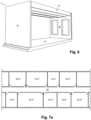
- a central circulation with small surface rooms on each side of a central corridor 101 of the building can be implemented.
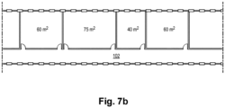
- a mono-oriented circulation with rooms of larger surface area on only one side of a side corridor 102 of the building can be implemented.
- a central circulation can be implemented in a first floor of the building, and a single-oriented circulation can be implemented in a second floor of the building.
- THE figures 7a And 7b also illustrate non-limiting examples of rooms in a building created from an assembly of modules 1 as described above. All modules 1 have a fixed width l and several modules have different depths p, in order to create rooms with different surface areas. In this particular example of figures 7a And 7b , the surface areas of the rooms are between 40 m 2 and 90 m 2 .
- Such manufacturing of a building using prefabricated modules 1 is also particularly suitable when the rooms constructed by assembling the modules 1 constitute the majority of the building's surface area.
- classrooms represent approximately half of the surface area of a school building.
- the building may also include structural, roofing, waterproofing and/or zincwork elements.
- the building may further comprise a roof module adapted to be placed above the prefabricated modules 1.
- the roof module can form an inaccessible, non-vegetable terrace.
- the roof module may include a frame without overhang, an insulating layer 303, a parapet, a roof covering, etc.
Landscapes
- Engineering & Computer Science (AREA)
- Architecture (AREA)
- Physics & Mathematics (AREA)
- Electromagnetism (AREA)
- Civil Engineering (AREA)
- Structural Engineering (AREA)
- Building Environments (AREA)
- Residential Or Office Buildings (AREA)
Applications Claiming Priority (1)
| Application Number | Priority Date | Filing Date | Title |
|---|---|---|---|
| FR2301114A FR3145576A1 (fr) | 2023-02-06 | 2023-02-06 | Module préfabriqué pour une salle modulaire |
Publications (1)
| Publication Number | Publication Date |
|---|---|
| EP4411084A1 true EP4411084A1 (de) | 2024-08-07 |
Family
ID=86657339
Family Applications (1)
| Application Number | Title | Priority Date | Filing Date |
|---|---|---|---|
| EP24156074.7A Pending EP4411084A1 (de) | 2023-02-06 | 2024-02-06 | Vorgefertigtes modul für einen modularen raum |
Country Status (2)
| Country | Link |
|---|---|
| EP (1) | EP4411084A1 (de) |
| FR (1) | FR3145576A1 (de) |
Citations (2)
| Publication number | Priority date | Publication date | Assignee | Title |
|---|---|---|---|---|
| FR3016180A1 (fr) * | 2014-01-08 | 2015-07-10 | Eiffage Construction | Module d'habitation, de bureau ou de stockage empilable pour realisation de constructions a etages a parois en bois, construction a etages |
| EP4098819A1 (de) * | 2021-06-04 | 2022-12-07 | VolkerWessels Intellectuele Eigendom B.V. | Bausystem mit holzfertigmodulen |
-
2023
- 2023-02-06 FR FR2301114A patent/FR3145576A1/fr active Pending
-
2024
- 2024-02-06 EP EP24156074.7A patent/EP4411084A1/de active Pending
Patent Citations (2)
| Publication number | Priority date | Publication date | Assignee | Title |
|---|---|---|---|---|
| FR3016180A1 (fr) * | 2014-01-08 | 2015-07-10 | Eiffage Construction | Module d'habitation, de bureau ou de stockage empilable pour realisation de constructions a etages a parois en bois, construction a etages |
| EP4098819A1 (de) * | 2021-06-04 | 2022-12-07 | VolkerWessels Intellectuele Eigendom B.V. | Bausystem mit holzfertigmodulen |
Also Published As
| Publication number | Publication date |
|---|---|
| FR3145576A1 (fr) | 2024-08-09 |
Similar Documents
| Publication | Publication Date | Title |
|---|---|---|
| RU2678341C2 (ru) | Модульное здание | |
| WO2008031989A2 (fr) | Edifice, notamment d ' habitation compose des cadres et poteaux et procede de son montage1 | |
| FR3086309A1 (fr) | Systeme de construction modulaire | |
| CN104631622A (zh) | 一种可拆卸式快装野外宿营房 | |
| BE1028666B1 (fr) | Module constructif tridimensionnel préfabriqué | |
| EP4411084A1 (de) | Vorgefertigtes modul für einen modularen raum | |
| JP2008196144A (ja) | 住宅 | |
| CN214461591U (zh) | 一种钢结构框架的装配式外围护墙板 | |
| JP7372276B2 (ja) | 躯体補強構造 | |
| EP0081496B1 (de) | Industrialisiertes gebäudesystem aus metall, mit mehreren stockwerken und in der werkstatt hergestellten elementen | |
| WO2020117115A1 (en) | Building element, modular housing units, buildings and method | |
| FR2866365A1 (fr) | Module pour systeme constructif modulaire | |
| FR3050468A1 (fr) | Procede de realisation d’un batiment demontable, et batiment correspondant. | |
| EP0173622B1 (de) | Vorgefertigte Einrichtungseinheit, insbesondere sanitäre Einheit | |
| FR2610022A1 (fr) | Systeme constructif, par cadres bois modulaires, formant structures, et leur procede de montage | |
| FR3003878A3 (fr) | Construction comportant des cloisons amovibles | |
| FR3107067A1 (fr) | Elément modulaire écologique pour la construction d’un bâtiment | |
| FR3016180A1 (fr) | Module d'habitation, de bureau ou de stockage empilable pour realisation de constructions a etages a parois en bois, construction a etages | |
| FR3155848A1 (fr) | Méthode de surélévation non-destructive d’un bâtiment | |
| FR2930569A1 (fr) | Bouclier d'enceinte pour batiment prefabrique, procede de fabrication d'un tel batiment et batiment comportant un tel bouclier | |
| RU2800657C2 (ru) | Модульное здание | |
| BE889198A (fr) | Systeme de batiment industrialise metallique a etages avec elements paracheves en atelier | |
| FR2491112A1 (fr) | Bardeau pour couvertures en tuiles plates | |
| FR3098228A1 (fr) | Module de construction à ossature métallique et bâtiment comprenant un ou plusieurs modules de ce type | |
| FR2602532A1 (fr) | Construction a elements modulables prefabriques avec ossature primaire legere et maconnerie peripherique |
Legal Events
| Date | Code | Title | Description |
|---|---|---|---|
| PUAI | Public reference made under article 153(3) epc to a published international application that has entered the european phase |
Free format text: ORIGINAL CODE: 0009012 |
|
| STAA | Information on the status of an ep patent application or granted ep patent |
Free format text: STATUS: THE APPLICATION HAS BEEN PUBLISHED |
|
| AK | Designated contracting states |
Kind code of ref document: A1 Designated state(s): AL AT BE BG CH CY CZ DE DK EE ES FI FR GB GR HR HU IE IS IT LI LT LU LV MC ME MK MT NL NO PL PT RO RS SE SI SK SM TR |
|
| STAA | Information on the status of an ep patent application or granted ep patent |
Free format text: STATUS: REQUEST FOR EXAMINATION WAS MADE |
|
| 17P | Request for examination filed |
Effective date: 20250207 |