EP3976906B1 - Pendelmassendämpfer - Google Patents
Pendelmassendämpfer Download PDFInfo
- Publication number
- EP3976906B1 EP3976906B1 EP20727981.1A EP20727981A EP3976906B1 EP 3976906 B1 EP3976906 B1 EP 3976906B1 EP 20727981 A EP20727981 A EP 20727981A EP 3976906 B1 EP3976906 B1 EP 3976906B1
- Authority
- EP
- European Patent Office
- Prior art keywords
- mass
- pendulum
- unit
- spring system
- damper according
- Prior art date
- Legal status (The legal status is an assumption and is not a legal conclusion. Google has not performed a legal analysis and makes no representation as to the accuracy of the status listed.)
- Active
Links
Images


Classifications
-
- E—FIXED CONSTRUCTIONS
- E04—BUILDING
- E04H—BUILDINGS OR LIKE STRUCTURES FOR PARTICULAR PURPOSES; SWIMMING OR SPLASH BATHS OR POOLS; MASTS; FENCING; TENTS OR CANOPIES, IN GENERAL
- E04H9/00—Buildings, groups of buildings or shelters adapted to withstand or provide protection against abnormal external influences, e.g. war-like action, earthquake or extreme climate
- E04H9/02—Buildings, groups of buildings or shelters adapted to withstand or provide protection against abnormal external influences, e.g. war-like action, earthquake or extreme climate withstanding earthquake or sinking of ground
- E04H9/021—Bearing, supporting or connecting constructions specially adapted for such buildings
- E04H9/0215—Bearing, supporting or connecting constructions specially adapted for such buildings involving active or passive dynamic mass damping systems
-
- F—MECHANICAL ENGINEERING; LIGHTING; HEATING; WEAPONS; BLASTING
- F16—ENGINEERING ELEMENTS AND UNITS; GENERAL MEASURES FOR PRODUCING AND MAINTAINING EFFECTIVE FUNCTIONING OF MACHINES OR INSTALLATIONS; THERMAL INSULATION IN GENERAL
- F16F—SPRINGS; SHOCK-ABSORBERS; MEANS FOR DAMPING VIBRATION
- F16F7/00—Vibration-dampers; Shock-absorbers
- F16F7/10—Vibration-dampers; Shock-absorbers using inertia effect
- F16F7/104—Vibration-dampers; Shock-absorbers using inertia effect the inertia member being resiliently mounted
-
- E—FIXED CONSTRUCTIONS
- E04—BUILDING
- E04B—GENERAL BUILDING CONSTRUCTIONS; WALLS, e.g. PARTITIONS; ROOFS; FLOORS; CEILINGS; INSULATION OR OTHER PROTECTION OF BUILDINGS
- E04B1/00—Constructions in general; Structures which are not restricted either to walls, e.g. partitions, or floors or ceilings or roofs
- E04B1/62—Insulation or other protection; Elements or use of specified material therefor
- E04B1/92—Protection against other undesired influences or dangers
- E04B1/98—Protection against other undesired influences or dangers against vibrations or shocks; against mechanical destruction, e.g. by air-raids
-
- F—MECHANICAL ENGINEERING; LIGHTING; HEATING; WEAPONS; BLASTING
- F16—ENGINEERING ELEMENTS AND UNITS; GENERAL MEASURES FOR PRODUCING AND MAINTAINING EFFECTIVE FUNCTIONING OF MACHINES OR INSTALLATIONS; THERMAL INSULATION IN GENERAL
- F16F—SPRINGS; SHOCK-ABSORBERS; MEANS FOR DAMPING VIBRATION
- F16F7/00—Vibration-dampers; Shock-absorbers
- F16F7/10—Vibration-dampers; Shock-absorbers using inertia effect
-
- F—MECHANICAL ENGINEERING; LIGHTING; HEATING; WEAPONS; BLASTING
- F03—MACHINES OR ENGINES FOR LIQUIDS; WIND, SPRING, OR WEIGHT MOTORS; PRODUCING MECHANICAL POWER OR A REACTIVE PROPULSIVE THRUST, NOT OTHERWISE PROVIDED FOR
- F03D—WIND MOTORS
- F03D13/00—Assembly, mounting or commissioning of wind motors; Arrangements specially adapted for transporting wind motor components
- F03D13/20—Arrangements for mounting or supporting wind motors; Masts or towers for wind motors
-
- F—MECHANICAL ENGINEERING; LIGHTING; HEATING; WEAPONS; BLASTING
- F05—INDEXING SCHEMES RELATING TO ENGINES OR PUMPS IN VARIOUS SUBCLASSES OF CLASSES F01-F04
- F05B—INDEXING SCHEME RELATING TO WIND, SPRING, WEIGHT, INERTIA OR LIKE MOTORS, TO MACHINES OR ENGINES FOR LIQUIDS COVERED BY SUBCLASSES F03B, F03D AND F03G
- F05B2260/00—Function
- F05B2260/50—Kinematic linkage, i.e. transmission of position
- F05B2260/502—Kinematic linkage, i.e. transmission of position involving springs
-
- F—MECHANICAL ENGINEERING; LIGHTING; HEATING; WEAPONS; BLASTING
- F05—INDEXING SCHEMES RELATING TO ENGINES OR PUMPS IN VARIOUS SUBCLASSES OF CLASSES F01-F04
- F05B—INDEXING SCHEME RELATING TO WIND, SPRING, WEIGHT, INERTIA OR LIKE MOTORS, TO MACHINES OR ENGINES FOR LIQUIDS COVERED BY SUBCLASSES F03B, F03D AND F03G
- F05B2260/00—Function
- F05B2260/96—Preventing, counteracting or reducing vibration or noise
- F05B2260/964—Preventing, counteracting or reducing vibration or noise by damping means
Definitions
- the present invention relates to a tuned pendulum mass damper according to claim 1 damping oscillation of tall buildings, towers or similar flexible structures.
- the pendulum mass damper is directed to applications requiring a low frequency tuned mass damper (TMD) reducing a e.g. wind or earthquake induced displacement response of the construction.
- TMD tuned mass damper
- TMD Tuned Mass Damper
- harmonic absorber is a device mounted to a specific location in a structure, so as to reduce the amplitude of vibration to an acceptable level whenever a strong lateral force such as an earthquake or high wind hit.
- Civil structures like high-rise buildings, or industrial applications such as wind turbines is now commonly exceeding 100 m in height and as the natural frequency of such structures decrease with the height, a tuned mass damper able to handle a low frequency is more often required.
- a TMD can either be included during the initial concept design of a building to reduce the size of vertical or horizontal elements or as a retrofit to an existing structure where vibration and acceleration issues are determined.
- TMD Some of the major considerations when installing a TMD, is the location of the TMD and effect of the chosen location to space allocation.
- a well-known pendulum tuned mass damper is the one built for Taipei 101 comprising a spherical Tuned Mass Damper weighing approximately 730 tons and costing around $4 million, the spherical mass is suspended in cables inside a metal frame allowing the mass to swing in all directions, however, the TMD reaches from the 87 th to the 91 st floor, i.e. around 15 meters in height.
- US 2017/0328058 discloses a pendulum damper for damping undesired vibrations in vibration sensitive systems such as tall buildings and towers, in particular wind turbines.
- a pendulum damper according to this document comprises a damper mass suspended from a top-point in a cable or the like, and a spring device installed in connection with the damper mass.
- the spring device is installed in such a way that its overall spring force acts essentially in the vertical direction allowing an adjustment of the damper frequency without changing the pendulum length by providing the pendulum damper ( n e ⁇ 1 2 ⁇ ⁇ g l ).
- US 6 045 090 A discloses a device for reducing vibrations of a rotor of a rotary-wing aircraft having an oscillating mass (M1), the mass (M1) is balanced by a first spring system (7) and supported by a carrying part (10) to maintain a vertical position, the carrying part (10) carrying the mass (M1) in the vertical direction extends between the mass (M1) and a position (O) below the mass (M1), i.e. the weight of the mass (M1) is supported from a point or level below the mass (1).
- the supporting part (10) of D1 is directly attached to the mass (M1).
- the present invention relates to a tuned mass damper according to claim 1, and, more particularly, to a pendulum tuned mass damper capable of damping a dynamic response of a variety of structural systems vibrating horizontally at low frequencies.
- the objective of the present invention is to provide a pendulum tuned mass damper according to claim 1, which is compact, maintenance-free and versatile.
- a further objective of the invention is to obtain an acceptable serviceability or comfort for users of the structures, also the invention will be efficient for obtaining an acceptable safety level avoiding exceedance of the ultimate limit state of the structure.
- the present invention may in particular relate to a suspended inverted pendulum mass damper.
- the invention relates to a pendulum mass damper according to claim 1, for damping oscillations of a structure comprising a mass (1) balanced by a first spring system (2a, 2b, 2c) and supported by a carrying part (4) to maintain a vertical position, the carrying part (4) carrying the mass (1) in the vertical direction extends between the mass (1) and a position (C) below the mass (1), i.e.
- the weight of the mass (1) is carried or supported from or at a point or level below the mass (1), wherein the mass (1) at the position (C) below the mass is fixed and/or connected to a unit (5) constituting a base of a supporting system for the mass (1) which unit (5) is floating i.e. the unit (5) can move either horizontally or both horizontally and vertically.
- the pendulum mass damper When the lower end of the pendulum mass damper can move horizontally, the pendulum becomes more stable while still working at low frequencies.
- the effective length of the inverted pendulum is extended, meaning that the point of rotation is situated in an imaginary point below the damper application.
- the increased pendulum length leads to a reduced angle of rotation of the pendulum when a fixed horizontal displacement of the pendulum mass is sought.
- a reduction of the angle of rotation will improve the stability performance and effective vibrating mass of the low-frequency damper application.
- the first mode is the main objective of this application.
- the spring configuration can be selected in order to tune both the first and second mode. This can potentially be utilized to damp to different structural modes with only one damper configuration.
- the unit (5) may be constituted of a floating part, such as a plate or another suitable shape, e.g. being balanced by flexible parts such as a second spring system (8).
- the carrying part (4) may comprise a central carrying part (4) extending from a suspension frame (7) to the position (C).
- the first spring system (2a, 2b, 2c) balances the mass (1) horizontally and is positioned above, below or at approximately the same vertical level as the mass (1).
- the first spring system (2a, 2b, 2c) balances the mass (1) horizontally and is attached or fixed at the central axis.
- the first spring system (2a, 2b, 2c) may be attached to or fixed above the vertical level of the mass (1) within a distance of the top of the mass being less than 20%, e.g. less than 10% or e.g. less than 5%, from the total length of the pendulum measured from the central point (C) to the fastening points or fastening level (F) of the springs.
- the damping system When the spring system is attached to the center axis above the mass - or close to the center axis - instead of to the perimeter of the mass, the damping system may be made more compact which is an advantage as the complete damping system then occupies less space horizontally.
- a first spring system 2a, 2b, 2c may advantageously be fixed to a point at, or close to, the center line through the mass 1 above the mass 1.
- a second springs system may according to such a solution be fixed to a point at, or close to the center line through the mass 1 below the mass.
- the first spring system (2a, 2b, 2c) may comprise at least 3 springs or at least balances the mass in three directions.
- the carrying part (4) may comprise a central carrying part (4) in form of one or more cables or similar extending from a suspension frame (7) to the position (C), or in form of a rigid beam e.g. made of steel or similarly rigid material extending from the mass (1) to the position (C).
- the carrying part (4) also may comprise support parts (3) e.g. in form of one or more rigid beams or similar part(s) extending from the mass (1) to the unit (5) positioned below the mass (1) which support part(s) may be resting on the unit (5).
- support parts (3) e.g. in form of one or more rigid beams or similar part(s) extending from the mass (1) to the unit (5) positioned below the mass (1) which support part(s) may be resting on the unit (5).
- the unit (5) comprises a joint allowing either the support part(s) (3) or the carrying part(s) (4) to pivot relative to the unit (5).
- the joint may have 1, 2 or 3 degrees of freedom i.e. the joint may allow the mass (1) to pivot relative to the unit (5) in one, two or more than two directions.
- the invention also relates to structure comprising a tuned pendulum mass damper as disclosed above.
- the structure is a building, wind turbine tower, chimney or other towers or similar flexible constructions.
- the structure may be higher than 10 m or higher than 50 m, preferably higher than 100 m and sometimes higher than 300 m.
- the pendulum mass damper may be placed within the upper 20% of the structure, normally within the upper 10% of the structure. Sometimes it will be placed at other heights.
- the structure may be a building, a wind turbine tower, a chimney or other towers or structures having a height over 9 m.
- the present invention relates to a tuned pendulum mass damper according to claim 1, such as an inverted pendulum mass damper which may be suspended.
- a pendulum mass damper is characterized by that the mass moves in a spherical plane which sphere, or spherical plane is defined by a central point C.
- the natural frequency of an inverted pendulum according to the present invention is not determined by the length of the pendulum as the natural frequency of an ordinary pendulum, instead the natural frequency is influenced by a spring system stabilizing the horizontal position of the mass. This makes it possible to reduce the height of the tuned mass damper making the mass damper significantly more compact while the tuned mass damper may still be able to compensate for vibrations at low frequency.
- the pendulum mass damper according to the present invention should normally be installed in top of a building to perform optimally, and as a pendulum mass damper according to the invention requires minimum vertical space for installation, more space may be available on top floors compared to top floors of buildings where a traditional pendulum mass damper is installed. Contrary to a traditional gravity pendulum, the achievement of an aimed natural frequency does not necessarily involve varying the height of the mass damper. Instead, it can be obtained by adjusting damper mass and spring stiffness. Hence, pendulum dimensions may be maintained.
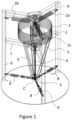
- Figs. 1-3 illustrates a first embodiment of the invention where the mass of the pendulum is suspended
- figs. 4-6 illustrates a second embodiment of the invention where the mass of the pendulum is supported by a rigid beam.
- That the pendulum mass damper is suspended means that the weight of the mass of the damper is carried by a cable or a similar structure which extends from a level or point above the central point C and down to the central point C. I.e. the force keeping the mass at its vertical position is a tension or pulling force.
- An inverted pendulum mass damper according to the invention may consist of simple mechanical components and bolted connections requiring only minimal maintenance during the lifetime of the device at the position of installation.
- Figs. 1-3 show a first embodiment of a pendulum mass damper according to the invention, where fig. 1 shows an upper side view of the first embodiment, fig. 2 shows a side view of the same embodiment and fig. 3 shows a top view of the same embodiment.
- the pendulum mass damper comprises a damper mass 1 which is balanced horizontally by a first spring system comprising three springs 2a, 2b, 2c or more.
- the damper mass shown in fig. 1 is of a cylindrical shape and consists of a series of smaller cylindrical masses, centrally drilled, which are installed and piled up on a vertical tube.
- the damper mass 1 may have any shape e.g. cylindrical or spherical or different, and weight, as the shape and weight of the mass are adapted to the structure in which it is desired to damp vibrations.
- the first spring system is normally constituted of one or more springs positioned above, below or at the same level as the mass 1, the spring(s) of the first spring system provide a horizontal force balancing the mass and advantageously the spring(s) are mounted close to the mass 1. That the springs are mounted "close" to the mass 1 means that the length between the top of the mass 1 and the fastening point or fastening level of the springs deviates less than 20%, e.g. less than 10% or e.g. less than 5%, from the total length of the pendulum measured from the central point C to the fastening points or fastening level of the springs.
- the fastening point or fastening level of the springs will normally be positioned at the top of the pendulum.
- the spring system may comprise any number of springs, e.g. the spring system may comprise at least two springs e.g. positioned opposite each other i.e. with a distance of 180° between the springs, or at least three springs i.e. with a distance of 120° between each pair of springs or at least four springs i.e. with a distance of at least 90° between each pair of springs.
- the springs are shown as coil or helical springs, but in general, the springs of the spring system may be of any type of compression or tension springs.
- the complete spring system comprising the first 2a, 2b, 2c and second 8 spring system is aimed at providing the system with the right stiffness, and thus right natural frequency.
- the tuned pendulum mass damper can either be symmetric or not, meaning that the suspended inverted pendulum frequency may either be identical for any moving direction or may vary in a desired manner. This allows the pendulum mass damper to perform horizontally in two-dimensions for any direction of motion.
- springs of the first spring system may be position in an inclined position, i.e. instead of providing a force in a horizontal direction, each or part of the springs of the first spring system may provide a force in both a horizontal and in a vertical direction.
- a first spring system may comprise at least three springs or is at least connected to springs in three directions e.g. symmetrically distributed around the mass.
- the first spring system comprises four springs or is balanced in four directions, the system will be stable, but the stiffness will not be symmetric.
- the pendulum mass damper in fig. 1-3 is mounted in an external frame 6, the frame 6 is attached to or is part of a structure such as a high building or tower being subjected to vibrations which vibrations would cause the structure to oscillate if no damper is present, i.e. the frame 6 does not move but is stationary relative to the structure.
- the pendulum mass damper further comprises one or more support part(s) 3 which helps maintaining the mass 1 in a vertical position, the support part(s) 3 are attached or fixed to the mass 1 and extends between the mass 1 and a unit 5 comprising a central point C being center of a sphere constituting a spherical plane in which the mass 1 moves.
- the unit 5 is positioned below the mass 1 i.e. the weight of the mass 1 is supported at a point/level below the mass 1, and the unit 5 may be understood to constitute the base of a supporting system for the mass 1.
- the unit 5 may be constituted of a part of the frame 6, or alternatively, the unit 5 may be constituted of a separate floating part, such as a plate or another suitable shape, being attached to the frame 6 by flexible parts e.g. a second spring system.
- the central point C moves together with the unit 5 changing the spherical plane in which the mass 1 moves.
- the unit 5 is a floating part attached to the frame 6 by a second spring system 8 which second spring system 8 comprises 3 springs evenly distributed around the unit 5.
- the number of springs in the second spring system is not significant, but normally the springs of this spring system may be very stiff allowing very limited horizontal movement between the frame 6 and a unit 5 constituted of a floating part thereby maintaining tension between the unit 5 and the frame 6.
- a pendulum mass damper may also comprise a central carrying part 4 carrying the mass 1 and being connected to a central point C.
- a central carrying part 4 may be constituted of e.g. one or more cables or similar, or of a rigid beam.
- the central carrying part 4 may comprise support parts 3 forming a connection between the mass 1 and the central point C without such support parts 3 may comprise one or more rigid beams or similar part(s) extending from the mass 1 to the unit 5.
- the carrying part 4 of the first embodiment is constituted of one or more cables or similar suspension means which suspension means are extending between a suspension frame 7 and the unit 5.
- the suspension frame 7 comprises three beams which extend between a central point or a centrally positioned plate and the frame 6, and the carrying part 4 comprises a cable extending from the central point or plate to the unit 5.
- the unit 5 may comprise a joint having 1, 2 or 3 degrees of freedom i.e. the joint may allow the mass 1 and the supporting parts 3 to pivot relative to the unit 5.
- the unit 5 and the carrying part 4 do not pivot as the second spring system will strive to maintain a constant horizontal and vertical position of the unit 5, whereas the mass 1 and the supporting parts 3 pivot at least back and forth in one direction, possibly in two directions and possibly in three or more directions.
- Figs. 4-6 show a second embodiment of a pendulum mass damper according to the invention, where fig. 4 shows an upper side view of the second embodiment, fig. 5 shows a side view of the second embodiment and fig. 6 shows a top view of the second embodiment.
- the pendulum mass damper comprises a damper mass 1 being balanced horizontally by a first spring system comprising three springs 2a, 2b, 2c.
- the damper mass shown in fig. 4-6 is of a cylindrical shape and consists of a series of smaller cylindrical masses, centrally drilled, which are installed and piled up on a vertical tube.
- the damper mass 1 may have any shape e.g. cylindrical or spherical or different, and any weight, as the shape and weight of the mass are adapted to the structure in which it is desired to damp vibrations.
- the pendulum mass damper in fig. 4-6 is mounted in an external frame 6, which frame 6 is attached to or is part of a structure such as a high building or tower being subjected to vibrations which vibrations would cause the structure to oscillate if no damper is present, i.e. the frame is stationary relative to the structure.
- the pendulum mass damper comprises a central carrying part 4 attached or fixed to the mass 1 and extending between the mass 1 and the unit 5 comprising a central point C being center of a sphere constituting the spherical plane in which the mass 1 moves.
- the unit 5 is positioned below the mass 1 i.e.
- the weight of the mass 1 is supported at a point/level below the mass 1, and the unit 5 may be understood to constitute the base of a supporting system for the mass 1.
- the unit 5 of the second embodiment may comprise a ball joint and the carrying part 4 may then comprise a ball-shaped end part supported by this joint.
- the unit 5 may comprise any joint allowing movement in all directions.
- the unit 5 may comprise a lower surface provided with wheels or other means adapted to slide over a contact surface of the structure or a frame fixed to the structure, and the unit 5 may be attached to a frame 6 of the structure by a second spring system 8 as described in connection with the first embodiment.
- the stiffness configuration of the second spring system 8 is important for the performance of the damper according to this embodiment. The number of springs and the stiffness can be changed in the same way as the springs of the first spring system.
- the unit 5 may comprise a joint having 1, 2 or 3 degrees of freedom i.e. the joint may allow the mass 1 and the supporting parts 3 to pivot relative to the unit 5.
- the pendulum mass damper becomes versatile, and adoptable to damp the dynamic response of a variety of slender structures, such as high-rise buildings and wind turbine towers having a natural frequency within the range [0.05 ; 0.3] Hz (equivalent to a wire length of a traditional pendulum in the range [99 ; 2.8] m).
- This band represents only a sub-group of frequencies which the damper is meant for and the frequency can be regulated according to the application purpose.
- the pendulum mass damper according to the invention would, in principle, be capable of acting for infinitesimally small frequencies.
Landscapes
- Engineering & Computer Science (AREA)
- Architecture (AREA)
- General Engineering & Computer Science (AREA)
- Environmental & Geological Engineering (AREA)
- Business, Economics & Management (AREA)
- Emergency Management (AREA)
- Mechanical Engineering (AREA)
- Civil Engineering (AREA)
- Structural Engineering (AREA)
- Physics & Mathematics (AREA)
- Electromagnetism (AREA)
- Vibration Prevention Devices (AREA)
- Buildings Adapted To Withstand Abnormal External Influences (AREA)
Claims (12)
- Abgestimmter Pendelmassendämpfer zum Dämpfen von Schwingungen einer Struktur umfassend eine Masse (1), ein erstes Federsystem (2a, 2b, 2c) und ein Tragteil (4), wobei die Masse (1) vom ersten Federsystem (2a, 2b, 2c) ausgeglichen und vom Tragteil (4) getragen wird, um eine vertikale Position der Masse beizubehalten, wobei das die Masse (1) in der vertikalen Richtung tragende Tragteil (4) sich zwischen der Masse (1) und einer Position (C) unterhalb der Masse (1) erstreckt, d.h. das Gewicht der Masse (1) von oder an einem Punkt oder einer Ebene unterhalb der Masse (1) getragen oder abgestützt wird, dadurch gekennzeichnet, dass die Masse (1) an der Position (C) unterhalb der Masse an einer Einheit (5) fixiert und/oder damit verbunden ist, die eine Basis eines Stützsystems für die Masse (1) bildet, welche Einheit (5) schwimmend ist, d.h. die Einheit (5) sich entweder horizontal oder sowohl horizontal als auch vertikal bewegen kann.
- Pendelmassendämpfer nach Anspruch 1, wobei die Einheit (5) aus einem schwimmenden Teil, wie etwa einer Platte oder einer anderen geeigneten Form, besteht, z.B. von flexiblen Teilen wie etwa einem zweiten Federsystem (8) ausgeglichen wird.
- Pendelmassendämpfer nach einem der vorhergehenden Ansprüche, wobei das Tragteil (4) ein zentrales, sich von einem Aufhängerahmen (7) zur Position (C) erstreckendes Tragteil (4) umfasst.
- Pendelmassendämpfer nach einem der vorhergehenden Ansprüche, wobei das erste Federsystem (2a, 2b, 2c) die Masse (1) horizontal ausgleicht und oberhalb, unterhalb oder auf ungefähr derselben vertikalen Ebene wie die Masse (1) angeordnet ist.
- Pendelmassendämpfer nach einem der vorhergehenden Ansprüche, wobei das erste Federsystem (2a, 2b, 2c) die Masse (1) horizontal ausgleicht und an der Mittelachse oberhalb der vertikalen Ebene der Masse (1) innerhalb eines Abstandes der Spitze der Masse befestigt oder fixiert ist, der weniger als 20 %, z.B. weniger als 10 % oder z.B. weniger als 5 %, von der Gesamtlänge des Pendels gemessen vom Mittelpunkt (C) bis zu den Befestigungspunkten oder der Befestigungsebene (F) der Federn beträgt.
- Pendelmassendämpfer nach einem der vorhergehenden Ansprüche, wobei das erste Federsystem (2a, 2b, 2c) mindestens 3 Federn umfasst oder zumindest die Masse in drei Richtungen ausgleicht.
- Pendelmassendämpfer nach einem der vorhergehenden Ansprüche, wobei das Tragteil (4) ein zentrales Tragteil (4) in Form von einem oder mehreren Kabeln oder Ähnlichem, die sich von einem Aufhängerahmen (7) zur Position (C) erstrecken, oder in Form eines starren, z.B. aus Stahl oder ähnlich starrem Material hergestellten Balkens, der sich von der Masse (1) zur Position (C) erstreckt, umfasst.
- Pendelmassendämpfer nach einem der vorhergehenden Ansprüche, wobei das Tragteil (4) ebenfalls Stützteile (3), z.B. in Form von einem oder mehreren starren Balken oder einem ähnlichen Teil bzw. ähnlichen Teilen, die sich von der Masse (1) zur Einheit (5) erstrecken, die unterhalb der Masse (1) angeordnet ist, welches Stützteil bzw. welche Stützteile auf der Einheit (5) aufliegen kann bzw. können, umfasst.
- Pendelmassendämpfer nach einem der vorhergehenden Ansprüche, wobei die Einheit (5) ein Gelenk umfasst, das es ermöglicht, dass entweder das Stützteil bzw. die Stützteile (3) oder das Tragteil bzw. die Tragteile (4) relativ zur Einheit (5) schwenken kann bzw. können.
- Pendelmassendämpfer nach Anspruch 8, wobei das Gelenk 1, 2 oder 3 Freiheitsgrade aufweist, d.h. das Gelenk es ermöglichen kann, dass die Masse (1) relativ zur Einheit (5) in eine, zwei oder mehr als zwei Richtungen schwenken kann.
- Struktur umfassend einen Pendelmassendämpfer nach einem der Ansprüche 1 bis 10.
- Struktur nach Anspruch 11, wobei es sich bei der Struktur um ein Gebäude, einen Windturbinen-Turm, einen Schornstein oder andere Türme oder ähnliche flexible Konstruktionen handelt.
Applications Claiming Priority (2)
| Application Number | Priority Date | Filing Date | Title |
|---|---|---|---|
| DKPA201900632A DK180710B1 (en) | 2019-05-24 | 2019-05-24 | Pendulum mass damper |
| PCT/EP2020/064146 WO2020239590A1 (en) | 2019-05-24 | 2020-05-20 | Pendulum mass damper |
Publications (3)
| Publication Number | Publication Date |
|---|---|
| EP3976906A1 EP3976906A1 (de) | 2022-04-06 |
| EP3976906C0 EP3976906C0 (de) | 2024-02-14 |
| EP3976906B1 true EP3976906B1 (de) | 2024-02-14 |
Family
ID=70847367
Family Applications (1)
| Application Number | Title | Priority Date | Filing Date |
|---|---|---|---|
| EP20727981.1A Active EP3976906B1 (de) | 2019-05-24 | 2020-05-20 | Pendelmassendämpfer |
Country Status (6)
| Country | Link |
|---|---|
| US (1) | US12031352B2 (de) |
| EP (1) | EP3976906B1 (de) |
| CN (1) | CN113924400B (de) |
| DK (1) | DK180710B1 (de) |
| SG (1) | SG11202112465TA (de) |
| WO (1) | WO2020239590A1 (de) |
Families Citing this family (16)
| Publication number | Priority date | Publication date | Assignee | Title |
|---|---|---|---|---|
| ES2782195T3 (es) * | 2016-02-24 | 2020-09-11 | Fm Energie Gmbh & Co Kg | Aerogeneradores con cojinetes elásticos de péndulo de bolas |
| MX2022007886A (es) * | 2019-12-23 | 2022-09-23 | Nam Young Kim | Estructura de aislamiento sismico utilizando cimiento de cable. |
| CN113007033A (zh) * | 2021-03-02 | 2021-06-22 | 中国大唐集团新能源科学技术研究院有限公司 | 一种主轴内置调谐阻尼装置的风力发电机组 |
| EP4140932A1 (de) * | 2021-08-30 | 2023-03-01 | Siemens Gamesa Renewable Energy Innovation & Technology S.L. | Kletterkran zum aufrichten einer windturbine und verfahren zum aufrichten einer windturbine mit einem kletterkran |
| CN113513103B (zh) * | 2021-09-14 | 2021-12-17 | 中国电建集团山东电力建设第一工程有限公司 | 一种悬挂式复合调谐减振装置及方法 |
| CN113738818B (zh) * | 2021-11-03 | 2022-02-08 | 溧阳常大技术转移中心有限公司 | 一种可对面内任意位移激励隔振的二维隔振器 |
| CN115095624B (zh) * | 2022-06-16 | 2023-09-22 | 哈尔滨工程大学 | 弹性装置、控制方法、吸振器、隔振器及振动能量采集器 |
| JP7829177B2 (ja) * | 2022-07-21 | 2026-03-13 | 五洋建設株式会社 | 塔状構造物の制震構造及び制震構造付き塔状構造物の構築方法 |
| US12473957B2 (en) | 2022-11-02 | 2025-11-18 | Hsp Hochspannungsgeräte Gmbh | Electrically isolating tuned mass damper |
| CN116876688B (zh) * | 2023-07-21 | 2024-07-23 | 中联西北工程设计研究院有限公司 | 一种适用于超高层建筑的轻质复摆阻尼结构及方法 |
| EP4667772A1 (de) * | 2024-06-21 | 2025-12-24 | TotalEnergies OneTech | Schwingungskontrollvorrichtung |
| CN118835715B (zh) * | 2024-07-29 | 2025-09-26 | 哈尔滨工业大学(深圳)(哈尔滨工业大学深圳科技创新研究院) | 一种滚动式被动调谐质量阻尼器 |
| CN118933203B (zh) * | 2024-07-29 | 2025-09-23 | 哈尔滨工业大学(深圳)(哈尔滨工业大学深圳科技创新研究院) | 一种平动式被动调谐质量阻尼器 |
| CN119195366B (zh) * | 2024-11-27 | 2025-02-07 | 湖南大学 | 一种摆式调谐质量减振器 |
| CN119435633B (zh) * | 2024-12-17 | 2025-10-24 | 浙江大学 | 一种应用于海上浮式风机的多自由度非线性能量阱减振装置 |
| CN119878756B (zh) * | 2025-01-15 | 2025-10-21 | 中铁大桥局集团有限公司 | 一种刚性单摆式调谐质量阻尼装置及风机 |
Citations (8)
| Publication number | Priority date | Publication date | Assignee | Title |
|---|---|---|---|---|
| JPH0512791U (ja) * | 1991-08-02 | 1993-02-19 | 日本電信電話株式会社 | 倒立振子型制振装置 |
| JPH0656534U (ja) * | 1993-01-13 | 1994-08-05 | 住友重機械工業株式会社 | 倒立振子式制振装置 |
| JPH0754520A (ja) * | 1993-08-12 | 1995-02-28 | Nippon Steel Corp | 構造物の制振装置 |
| JPH1136664A (ja) * | 1997-07-17 | 1999-02-09 | Showa Electric Wire & Cable Co Ltd | 動吸振器 |
| JP2001349094A (ja) * | 2000-06-08 | 2001-12-21 | Sekisui House Ltd | 同調振り子式制振装置 |
| JP2011069104A (ja) * | 2009-09-25 | 2011-04-07 | Tatsuji Ishimaru | 制震装置及び制震構造物 |
| JP2013245765A (ja) * | 2012-05-25 | 2013-12-09 | Tokkyokiki Corp | マスダンパー型制振装置 |
| US20170328058A1 (en) * | 2014-12-05 | 2017-11-16 | Esm Energie-Und Schwingungstechnik Mitsch Gmbh | Adaptive oscillation damper having a vertical spring mechanism |
Family Cites Families (13)
| Publication number | Priority date | Publication date | Assignee | Title |
|---|---|---|---|---|
| US1761322A (en) * | 1928-04-09 | 1930-06-03 | George W Anderson | Foundation construction |
| JPS61274134A (ja) | 1985-05-29 | 1986-12-04 | Mitsubishi Heavy Ind Ltd | ダイナミツクダンパ− |
| JP2555204B2 (ja) | 1989-10-04 | 1996-11-20 | 鹿島建設株式会社 | 構造物の振動抑制方法 |
| NZ238798A (en) * | 1990-08-30 | 1993-11-25 | Mitsubishi Heavy Ind Ltd | Low height long period pendulum damping equipment for tall buildings |
| JPH0518439A (ja) * | 1991-07-09 | 1993-01-26 | Fujita Corp | 免震支持装置 |
| US5915508A (en) * | 1994-04-18 | 1999-06-29 | Minnesota Mining And Manufacturing Company | Tuned mass damper |
| FR2749901B1 (fr) * | 1996-06-12 | 2000-12-08 | Eurocopter France | Dispositif pour reduire les vibrations engendrees par un rotor de sustentation d'un aeronef a voilure tournante |
| DE19856500B4 (de) * | 1998-12-08 | 2005-12-08 | Franz Mitsch | Schwingungstilger |
| US20010032420A1 (en) * | 2000-01-25 | 2001-10-25 | Ma-Chi Chen | Gravity balance frame |
| WO2012144066A1 (ja) * | 2011-04-22 | 2012-10-26 | 三菱重工業株式会社 | 制振装置、風力発電装置及び制振方法 |
| CN103273502B (zh) * | 2013-06-19 | 2015-05-20 | 北京航空航天大学 | 基于可控刚度和可控阻尼的柔性机械臂减振装置与方法 |
| CN203499048U (zh) * | 2013-09-10 | 2014-03-26 | 隔而固(青岛)振动控制有限公司 | 摆式调谐质量阻尼器的频率调节装置 |
| CN207739674U (zh) * | 2017-12-20 | 2018-08-17 | 中冶建筑研究总院有限公司 | 一种装配式钢-混凝土组合结构住宅体系 |
-
2019
- 2019-05-24 DK DKPA201900632A patent/DK180710B1/en active IP Right Grant
-
2020
- 2020-05-20 US US17/612,307 patent/US12031352B2/en active Active
- 2020-05-20 CN CN202080038310.6A patent/CN113924400B/zh active Active
- 2020-05-20 EP EP20727981.1A patent/EP3976906B1/de active Active
- 2020-05-20 SG SG11202112465TA patent/SG11202112465TA/en unknown
- 2020-05-20 WO PCT/EP2020/064146 patent/WO2020239590A1/en not_active Ceased
Patent Citations (8)
| Publication number | Priority date | Publication date | Assignee | Title |
|---|---|---|---|---|
| JPH0512791U (ja) * | 1991-08-02 | 1993-02-19 | 日本電信電話株式会社 | 倒立振子型制振装置 |
| JPH0656534U (ja) * | 1993-01-13 | 1994-08-05 | 住友重機械工業株式会社 | 倒立振子式制振装置 |
| JPH0754520A (ja) * | 1993-08-12 | 1995-02-28 | Nippon Steel Corp | 構造物の制振装置 |
| JPH1136664A (ja) * | 1997-07-17 | 1999-02-09 | Showa Electric Wire & Cable Co Ltd | 動吸振器 |
| JP2001349094A (ja) * | 2000-06-08 | 2001-12-21 | Sekisui House Ltd | 同調振り子式制振装置 |
| JP2011069104A (ja) * | 2009-09-25 | 2011-04-07 | Tatsuji Ishimaru | 制震装置及び制震構造物 |
| JP2013245765A (ja) * | 2012-05-25 | 2013-12-09 | Tokkyokiki Corp | マスダンパー型制振装置 |
| US20170328058A1 (en) * | 2014-12-05 | 2017-11-16 | Esm Energie-Und Schwingungstechnik Mitsch Gmbh | Adaptive oscillation damper having a vertical spring mechanism |
Also Published As
| Publication number | Publication date |
|---|---|
| EP3976906A1 (de) | 2022-04-06 |
| CN113924400A (zh) | 2022-01-11 |
| DK180710B1 (en) | 2021-12-16 |
| EP3976906C0 (de) | 2024-02-14 |
| US12031352B2 (en) | 2024-07-09 |
| DK201900632A1 (en) | 2021-02-18 |
| CN113924400B (zh) | 2024-04-19 |
| SG11202112465TA (en) | 2021-12-30 |
| WO2020239590A1 (en) | 2020-12-03 |
| BR112021023508A2 (pt) | 2022-01-18 |
| US20220228393A1 (en) | 2022-07-21 |
Similar Documents
| Publication | Publication Date | Title |
|---|---|---|
| EP3976906B1 (de) | Pendelmassendämpfer | |
| WO2009027663A2 (en) | Tower | |
| KR20190135525A (ko) | 풍력 터빈 타워의 진동 댐핑 | |
| CA3045211C (en) | Compact spatial ellipsoidal mass pendulum | |
| WO2018196276A1 (zh) | 一种超低频液体质量调谐阻尼器 | |
| JPH05501441A (ja) | 振動絶縁システム | |
| CN109577363A (zh) | 一种球形铰链式超低频万向振动调谐质量阻尼器 | |
| KR20210025099A (ko) | 타워 댐퍼 | |
| JP2008190645A (ja) | 振動低減機構およびその諸元設定方法 | |
| CN109577361A (zh) | 频率阻尼可调式两自由度万向水平减振调谐质量阻尼器 | |
| WO2004003306A1 (en) | Simple pendulum with variable restoring force | |
| EP4145012A1 (de) | Schwingungsdämpfer | |
| RU2096565C1 (ru) | Динамический гаситель колебаний | |
| WO1992002743A1 (fr) | Dispositif amortisseutr de vibrations | |
| BR112021023508B1 (pt) | Amortecedor de massa tipo pendulo para amortecer oscilaqoes de uma estrutura e estrutura | |
| JP3840651B2 (ja) | 超高塔状タワーの制振構造 | |
| JPS6065932A (ja) | 振り子式動吸振器 | |
| CN109577362B (zh) | 一种球形轴承式超低频水平万向振动调谐质量阻尼器 | |
| CN119686208B (zh) | 一种水平多向低频调谐液体质量阻尼器 | |
| TWI872920B (zh) | 特別是針對細高型建築物的吸振構造,以及設立吸振構造的方法 | |
| JPH02282584A (ja) | 連結式2重振り子水槽ダンパー | |
| NZ234851A (en) | Pendulum type dynamic damper for controlling building vibrations | |
| JPH02282583A (ja) | 連結式振り子水槽ダンパー | |
| JPH0314094B2 (de) | ||
| UA58826A (uk) | Кульовий гаситель вимушених коливань із лінійно-в'язким опором |
Legal Events
| Date | Code | Title | Description |
|---|---|---|---|
| STAA | Information on the status of an ep patent application or granted ep patent |
Free format text: STATUS: UNKNOWN |
|
| STAA | Information on the status of an ep patent application or granted ep patent |
Free format text: STATUS: THE INTERNATIONAL PUBLICATION HAS BEEN MADE |
|
| PUAI | Public reference made under article 153(3) epc to a published international application that has entered the european phase |
Free format text: ORIGINAL CODE: 0009012 |
|
| STAA | Information on the status of an ep patent application or granted ep patent |
Free format text: STATUS: REQUEST FOR EXAMINATION WAS MADE |
|
| 17P | Request for examination filed |
Effective date: 20220103 |
|
| AK | Designated contracting states |
Kind code of ref document: A1 Designated state(s): AL AT BE BG CH CY CZ DE DK EE ES FI FR GB GR HR HU IE IS IT LI LT LU LV MC MK MT NL NO PL PT RO RS SE SI SK SM TR |
|
| RIN1 | Information on inventor provided before grant (corrected) |
Inventor name: HANSEN, SVEND OLE |
|
| DAV | Request for validation of the european patent (deleted) | ||
| DAX | Request for extension of the european patent (deleted) | ||
| GRAP | Despatch of communication of intention to grant a patent |
Free format text: ORIGINAL CODE: EPIDOSNIGR1 |
|
| STAA | Information on the status of an ep patent application or granted ep patent |
Free format text: STATUS: GRANT OF PATENT IS INTENDED |
|
| INTG | Intention to grant announced |
Effective date: 20230829 |
|
| GRAS | Grant fee paid |
Free format text: ORIGINAL CODE: EPIDOSNIGR3 |
|
| GRAA | (expected) grant |
Free format text: ORIGINAL CODE: 0009210 |
|
| STAA | Information on the status of an ep patent application or granted ep patent |
Free format text: STATUS: THE PATENT HAS BEEN GRANTED |
|
| AK | Designated contracting states |
Kind code of ref document: B1 Designated state(s): AL AT BE BG CH CY CZ DE DK EE ES FI FR GB GR HR HU IE IS IT LI LT LU LV MC MK MT NL NO PL PT RO RS SE SI SK SM TR |
|
| REG | Reference to a national code |
Ref country code: GB Ref legal event code: FG4D |
|
| REG | Reference to a national code |
Ref country code: CH Ref legal event code: EP |
|
| REG | Reference to a national code |
Ref country code: DE Ref legal event code: R096 Ref document number: 602020025670 Country of ref document: DE |
|
| REG | Reference to a national code |
Ref country code: IE Ref legal event code: FG4D |
|
| U01 | Request for unitary effect filed |
Effective date: 20240311 |
|
| U07 | Unitary effect registered |
Designated state(s): AT BE BG DE DK EE FI FR IT LT LU LV MT NL PT SE SI Effective date: 20240319 |
|
| PG25 | Lapsed in a contracting state [announced via postgrant information from national office to epo] |
Ref country code: IS Free format text: LAPSE BECAUSE OF FAILURE TO SUBMIT A TRANSLATION OF THE DESCRIPTION OR TO PAY THE FEE WITHIN THE PRESCRIBED TIME-LIMIT Effective date: 20240614 |
|
| U20 | Renewal fee for the european patent with unitary effect paid |
Year of fee payment: 5 Effective date: 20240528 |
|
| PG25 | Lapsed in a contracting state [announced via postgrant information from national office to epo] |
Ref country code: GR Free format text: LAPSE BECAUSE OF FAILURE TO SUBMIT A TRANSLATION OF THE DESCRIPTION OR TO PAY THE FEE WITHIN THE PRESCRIBED TIME-LIMIT Effective date: 20240515 |
|
| PG25 | Lapsed in a contracting state [announced via postgrant information from national office to epo] |
Ref country code: RS Free format text: LAPSE BECAUSE OF FAILURE TO SUBMIT A TRANSLATION OF THE DESCRIPTION OR TO PAY THE FEE WITHIN THE PRESCRIBED TIME-LIMIT Effective date: 20240514 Ref country code: HR Free format text: LAPSE BECAUSE OF FAILURE TO SUBMIT A TRANSLATION OF THE DESCRIPTION OR TO PAY THE FEE WITHIN THE PRESCRIBED TIME-LIMIT Effective date: 20240214 |
|
| PG25 | Lapsed in a contracting state [announced via postgrant information from national office to epo] |
Ref country code: ES Free format text: LAPSE BECAUSE OF FAILURE TO SUBMIT A TRANSLATION OF THE DESCRIPTION OR TO PAY THE FEE WITHIN THE PRESCRIBED TIME-LIMIT Effective date: 20240214 |
|
| PG25 | Lapsed in a contracting state [announced via postgrant information from national office to epo] |
Ref country code: RS Free format text: LAPSE BECAUSE OF FAILURE TO SUBMIT A TRANSLATION OF THE DESCRIPTION OR TO PAY THE FEE WITHIN THE PRESCRIBED TIME-LIMIT Effective date: 20240514 Ref country code: IS Free format text: LAPSE BECAUSE OF FAILURE TO SUBMIT A TRANSLATION OF THE DESCRIPTION OR TO PAY THE FEE WITHIN THE PRESCRIBED TIME-LIMIT Effective date: 20240614 Ref country code: HR Free format text: LAPSE BECAUSE OF FAILURE TO SUBMIT A TRANSLATION OF THE DESCRIPTION OR TO PAY THE FEE WITHIN THE PRESCRIBED TIME-LIMIT Effective date: 20240214 Ref country code: GR Free format text: LAPSE BECAUSE OF FAILURE TO SUBMIT A TRANSLATION OF THE DESCRIPTION OR TO PAY THE FEE WITHIN THE PRESCRIBED TIME-LIMIT Effective date: 20240515 Ref country code: ES Free format text: LAPSE BECAUSE OF FAILURE TO SUBMIT A TRANSLATION OF THE DESCRIPTION OR TO PAY THE FEE WITHIN THE PRESCRIBED TIME-LIMIT Effective date: 20240214 |
|
| PG25 | Lapsed in a contracting state [announced via postgrant information from national office to epo] |
Ref country code: PL Free format text: LAPSE BECAUSE OF FAILURE TO SUBMIT A TRANSLATION OF THE DESCRIPTION OR TO PAY THE FEE WITHIN THE PRESCRIBED TIME-LIMIT Effective date: 20240214 |
|
| PG25 | Lapsed in a contracting state [announced via postgrant information from national office to epo] |
Ref country code: PL Free format text: LAPSE BECAUSE OF FAILURE TO SUBMIT A TRANSLATION OF THE DESCRIPTION OR TO PAY THE FEE WITHIN THE PRESCRIBED TIME-LIMIT Effective date: 20240214 |
|
| PG25 | Lapsed in a contracting state [announced via postgrant information from national office to epo] |
Ref country code: SM Free format text: LAPSE BECAUSE OF FAILURE TO SUBMIT A TRANSLATION OF THE DESCRIPTION OR TO PAY THE FEE WITHIN THE PRESCRIBED TIME-LIMIT Effective date: 20240214 |
|
| PG25 | Lapsed in a contracting state [announced via postgrant information from national office to epo] |
Ref country code: CZ Free format text: LAPSE BECAUSE OF FAILURE TO SUBMIT A TRANSLATION OF THE DESCRIPTION OR TO PAY THE FEE WITHIN THE PRESCRIBED TIME-LIMIT Effective date: 20240214 |
|
| PG25 | Lapsed in a contracting state [announced via postgrant information from national office to epo] |
Ref country code: SK Free format text: LAPSE BECAUSE OF FAILURE TO SUBMIT A TRANSLATION OF THE DESCRIPTION OR TO PAY THE FEE WITHIN THE PRESCRIBED TIME-LIMIT Effective date: 20240214 |
|
| PG25 | Lapsed in a contracting state [announced via postgrant information from national office to epo] |
Ref country code: SM Free format text: LAPSE BECAUSE OF FAILURE TO SUBMIT A TRANSLATION OF THE DESCRIPTION OR TO PAY THE FEE WITHIN THE PRESCRIBED TIME-LIMIT Effective date: 20240214 Ref country code: SK Free format text: LAPSE BECAUSE OF FAILURE TO SUBMIT A TRANSLATION OF THE DESCRIPTION OR TO PAY THE FEE WITHIN THE PRESCRIBED TIME-LIMIT Effective date: 20240214 Ref country code: RO Free format text: LAPSE BECAUSE OF FAILURE TO SUBMIT A TRANSLATION OF THE DESCRIPTION OR TO PAY THE FEE WITHIN THE PRESCRIBED TIME-LIMIT Effective date: 20240214 Ref country code: CZ Free format text: LAPSE BECAUSE OF FAILURE TO SUBMIT A TRANSLATION OF THE DESCRIPTION OR TO PAY THE FEE WITHIN THE PRESCRIBED TIME-LIMIT Effective date: 20240214 |
|
| REG | Reference to a national code |
Ref country code: DE Ref legal event code: R097 Ref document number: 602020025670 Country of ref document: DE |
|
| PLBE | No opposition filed within time limit |
Free format text: ORIGINAL CODE: 0009261 |
|
| STAA | Information on the status of an ep patent application or granted ep patent |
Free format text: STATUS: NO OPPOSITION FILED WITHIN TIME LIMIT |
|
| REG | Reference to a national code |
Ref country code: CH Ref legal event code: PL |
|
| PG25 | Lapsed in a contracting state [announced via postgrant information from national office to epo] |
Ref country code: MC Free format text: LAPSE BECAUSE OF FAILURE TO SUBMIT A TRANSLATION OF THE DESCRIPTION OR TO PAY THE FEE WITHIN THE PRESCRIBED TIME-LIMIT Effective date: 20240214 |
|
| 26N | No opposition filed |
Effective date: 20241115 |
|
| PG25 | Lapsed in a contracting state [announced via postgrant information from national office to epo] |
Ref country code: MC Free format text: LAPSE BECAUSE OF FAILURE TO SUBMIT A TRANSLATION OF THE DESCRIPTION OR TO PAY THE FEE WITHIN THE PRESCRIBED TIME-LIMIT Effective date: 20240214 Ref country code: CH Free format text: LAPSE BECAUSE OF NON-PAYMENT OF DUE FEES Effective date: 20240531 |
|
| U20 | Renewal fee for the european patent with unitary effect paid |
Year of fee payment: 6 Effective date: 20250527 |
|
| PGFP | Annual fee paid to national office [announced via postgrant information from national office to epo] |
Ref country code: GB Payment date: 20250527 Year of fee payment: 6 |
|
| PGFP | Annual fee paid to national office [announced via postgrant information from national office to epo] |
Ref country code: NO Payment date: 20250530 Year of fee payment: 6 |
|
| PGFP | Annual fee paid to national office [announced via postgrant information from national office to epo] |
Ref country code: IE Payment date: 20250527 Year of fee payment: 6 |
|
| PG25 | Lapsed in a contracting state [announced via postgrant information from national office to epo] |
Ref country code: CY Free format text: LAPSE BECAUSE OF FAILURE TO SUBMIT A TRANSLATION OF THE DESCRIPTION OR TO PAY THE FEE WITHIN THE PRESCRIBED TIME-LIMIT; INVALID AB INITIO Effective date: 20200520 |
|
| PG25 | Lapsed in a contracting state [announced via postgrant information from national office to epo] |
Ref country code: HU Free format text: LAPSE BECAUSE OF FAILURE TO SUBMIT A TRANSLATION OF THE DESCRIPTION OR TO PAY THE FEE WITHIN THE PRESCRIBED TIME-LIMIT; INVALID AB INITIO Effective date: 20200520 |
|
| U1N | Appointed representative for the unitary patent procedure changed after the registration of the unitary effect |
Representative=s name: LARSEN & BIRKEHOLM A/S; DK |