EP3976906B1 - Pendulum mass damper - Google Patents
Pendulum mass damper Download PDFInfo
- Publication number
- EP3976906B1 EP3976906B1 EP20727981.1A EP20727981A EP3976906B1 EP 3976906 B1 EP3976906 B1 EP 3976906B1 EP 20727981 A EP20727981 A EP 20727981A EP 3976906 B1 EP3976906 B1 EP 3976906B1
- Authority
- EP
- European Patent Office
- Prior art keywords
- mass
- pendulum
- unit
- spring system
- damper according
- Prior art date
- Legal status (The legal status is an assumption and is not a legal conclusion. Google has not performed a legal analysis and makes no representation as to the accuracy of the status listed.)
- Active
Links
- 239000000725 suspension Substances 0.000 claims description 10
- 238000013016 damping Methods 0.000 claims description 8
- 230000010355 oscillation Effects 0.000 claims description 5
- 229910000831 Steel Inorganic materials 0.000 claims description 2
- 239000000463 material Substances 0.000 claims description 2
- 230000000284 resting effect Effects 0.000 claims description 2
- 239000010959 steel Substances 0.000 claims description 2
- 230000001133 acceleration Effects 0.000 description 3
- 238000010276 construction Methods 0.000 description 2
- 238000006073 displacement reaction Methods 0.000 description 2
- 230000005484 gravity Effects 0.000 description 2
- 238000009434 installation Methods 0.000 description 2
- 206010028813 Nausea Diseases 0.000 description 1
- 239000006096 absorbing agent Substances 0.000 description 1
- 230000006835 compression Effects 0.000 description 1
- 238000007906 compression Methods 0.000 description 1
- 230000000694 effects Effects 0.000 description 1
- 238000012423 maintenance Methods 0.000 description 1
- 239000002184 metal Substances 0.000 description 1
- 201000003152 motion sickness Diseases 0.000 description 1
- 230000008693 nausea Effects 0.000 description 1
- 230000001105 regulatory effect Effects 0.000 description 1
- 230000035939 shock Effects 0.000 description 1
- 230000000087 stabilizing effect Effects 0.000 description 1
- 238000005303 weighing Methods 0.000 description 1
Images


Classifications
-
- E—FIXED CONSTRUCTIONS
- E04—BUILDING
- E04H—BUILDINGS OR LIKE STRUCTURES FOR PARTICULAR PURPOSES; SWIMMING OR SPLASH BATHS OR POOLS; MASTS; FENCING; TENTS OR CANOPIES, IN GENERAL
- E04H9/00—Buildings, groups of buildings or shelters adapted to withstand or provide protection against abnormal external influences, e.g. war-like action, earthquake or extreme climate
- E04H9/02—Buildings, groups of buildings or shelters adapted to withstand or provide protection against abnormal external influences, e.g. war-like action, earthquake or extreme climate withstanding earthquake or sinking of ground
- E04H9/021—Bearing, supporting or connecting constructions specially adapted for such buildings
- E04H9/0215—Bearing, supporting or connecting constructions specially adapted for such buildings involving active or passive dynamic mass damping systems
-
- F—MECHANICAL ENGINEERING; LIGHTING; HEATING; WEAPONS; BLASTING
- F16—ENGINEERING ELEMENTS AND UNITS; GENERAL MEASURES FOR PRODUCING AND MAINTAINING EFFECTIVE FUNCTIONING OF MACHINES OR INSTALLATIONS; THERMAL INSULATION IN GENERAL
- F16F—SPRINGS; SHOCK-ABSORBERS; MEANS FOR DAMPING VIBRATION
- F16F7/00—Vibration-dampers; Shock-absorbers
- F16F7/10—Vibration-dampers; Shock-absorbers using inertia effect
- F16F7/104—Vibration-dampers; Shock-absorbers using inertia effect the inertia member being resiliently mounted
-
- E—FIXED CONSTRUCTIONS
- E04—BUILDING
- E04B—GENERAL BUILDING CONSTRUCTIONS; WALLS, e.g. PARTITIONS; ROOFS; FLOORS; CEILINGS; INSULATION OR OTHER PROTECTION OF BUILDINGS
- E04B1/00—Constructions in general; Structures which are not restricted either to walls, e.g. partitions, or floors or ceilings or roofs
- E04B1/62—Insulation or other protection; Elements or use of specified material therefor
- E04B1/92—Protection against other undesired influences or dangers
- E04B1/98—Protection against other undesired influences or dangers against vibrations or shocks; against mechanical destruction, e.g. by air-raids
-
- F—MECHANICAL ENGINEERING; LIGHTING; HEATING; WEAPONS; BLASTING
- F16—ENGINEERING ELEMENTS AND UNITS; GENERAL MEASURES FOR PRODUCING AND MAINTAINING EFFECTIVE FUNCTIONING OF MACHINES OR INSTALLATIONS; THERMAL INSULATION IN GENERAL
- F16F—SPRINGS; SHOCK-ABSORBERS; MEANS FOR DAMPING VIBRATION
- F16F7/00—Vibration-dampers; Shock-absorbers
- F16F7/10—Vibration-dampers; Shock-absorbers using inertia effect
-
- F—MECHANICAL ENGINEERING; LIGHTING; HEATING; WEAPONS; BLASTING
- F03—MACHINES OR ENGINES FOR LIQUIDS; WIND, SPRING, OR WEIGHT MOTORS; PRODUCING MECHANICAL POWER OR A REACTIVE PROPULSIVE THRUST, NOT OTHERWISE PROVIDED FOR
- F03D—WIND MOTORS
- F03D13/00—Assembly, mounting or commissioning of wind motors; Arrangements specially adapted for transporting wind motor components
- F03D13/20—Arrangements for mounting or supporting wind motors; Masts or towers for wind motors
-
- F—MECHANICAL ENGINEERING; LIGHTING; HEATING; WEAPONS; BLASTING
- F05—INDEXING SCHEMES RELATING TO ENGINES OR PUMPS IN VARIOUS SUBCLASSES OF CLASSES F01-F04
- F05B—INDEXING SCHEME RELATING TO WIND, SPRING, WEIGHT, INERTIA OR LIKE MOTORS, TO MACHINES OR ENGINES FOR LIQUIDS COVERED BY SUBCLASSES F03B, F03D AND F03G
- F05B2260/00—Function
- F05B2260/50—Kinematic linkage, i.e. transmission of position
- F05B2260/502—Kinematic linkage, i.e. transmission of position involving springs
-
- F—MECHANICAL ENGINEERING; LIGHTING; HEATING; WEAPONS; BLASTING
- F05—INDEXING SCHEMES RELATING TO ENGINES OR PUMPS IN VARIOUS SUBCLASSES OF CLASSES F01-F04
- F05B—INDEXING SCHEME RELATING TO WIND, SPRING, WEIGHT, INERTIA OR LIKE MOTORS, TO MACHINES OR ENGINES FOR LIQUIDS COVERED BY SUBCLASSES F03B, F03D AND F03G
- F05B2260/00—Function
- F05B2260/96—Preventing, counteracting or reducing vibration or noise
- F05B2260/964—Preventing, counteracting or reducing vibration or noise by damping means
Definitions
- the present invention relates to a tuned pendulum mass damper according to claim 1 damping oscillation of tall buildings, towers or similar flexible structures.
- the pendulum mass damper is directed to applications requiring a low frequency tuned mass damper (TMD) reducing a e.g. wind or earthquake induced displacement response of the construction.
- TMD tuned mass damper
- TMD Tuned Mass Damper
- harmonic absorber is a device mounted to a specific location in a structure, so as to reduce the amplitude of vibration to an acceptable level whenever a strong lateral force such as an earthquake or high wind hit.
- Civil structures like high-rise buildings, or industrial applications such as wind turbines is now commonly exceeding 100 m in height and as the natural frequency of such structures decrease with the height, a tuned mass damper able to handle a low frequency is more often required.
- a TMD can either be included during the initial concept design of a building to reduce the size of vertical or horizontal elements or as a retrofit to an existing structure where vibration and acceleration issues are determined.
- TMD Some of the major considerations when installing a TMD, is the location of the TMD and effect of the chosen location to space allocation.
- a well-known pendulum tuned mass damper is the one built for Taipei 101 comprising a spherical Tuned Mass Damper weighing approximately 730 tons and costing around $4 million, the spherical mass is suspended in cables inside a metal frame allowing the mass to swing in all directions, however, the TMD reaches from the 87 th to the 91 st floor, i.e. around 15 meters in height.
- US 2017/0328058 discloses a pendulum damper for damping undesired vibrations in vibration sensitive systems such as tall buildings and towers, in particular wind turbines.
- a pendulum damper according to this document comprises a damper mass suspended from a top-point in a cable or the like, and a spring device installed in connection with the damper mass.
- the spring device is installed in such a way that its overall spring force acts essentially in the vertical direction allowing an adjustment of the damper frequency without changing the pendulum length by providing the pendulum damper ( n e ⁇ 1 2 ⁇ ⁇ g l ).
- US 6 045 090 A discloses a device for reducing vibrations of a rotor of a rotary-wing aircraft having an oscillating mass (M1), the mass (M1) is balanced by a first spring system (7) and supported by a carrying part (10) to maintain a vertical position, the carrying part (10) carrying the mass (M1) in the vertical direction extends between the mass (M1) and a position (O) below the mass (M1), i.e. the weight of the mass (M1) is supported from a point or level below the mass (1).
- the supporting part (10) of D1 is directly attached to the mass (M1).
- the present invention relates to a tuned mass damper according to claim 1, and, more particularly, to a pendulum tuned mass damper capable of damping a dynamic response of a variety of structural systems vibrating horizontally at low frequencies.
- the objective of the present invention is to provide a pendulum tuned mass damper according to claim 1, which is compact, maintenance-free and versatile.
- a further objective of the invention is to obtain an acceptable serviceability or comfort for users of the structures, also the invention will be efficient for obtaining an acceptable safety level avoiding exceedance of the ultimate limit state of the structure.
- the present invention may in particular relate to a suspended inverted pendulum mass damper.
- the invention relates to a pendulum mass damper according to claim 1, for damping oscillations of a structure comprising a mass (1) balanced by a first spring system (2a, 2b, 2c) and supported by a carrying part (4) to maintain a vertical position, the carrying part (4) carrying the mass (1) in the vertical direction extends between the mass (1) and a position (C) below the mass (1), i.e.
- the weight of the mass (1) is carried or supported from or at a point or level below the mass (1), wherein the mass (1) at the position (C) below the mass is fixed and/or connected to a unit (5) constituting a base of a supporting system for the mass (1) which unit (5) is floating i.e. the unit (5) can move either horizontally or both horizontally and vertically.
- the pendulum mass damper When the lower end of the pendulum mass damper can move horizontally, the pendulum becomes more stable while still working at low frequencies.
- the effective length of the inverted pendulum is extended, meaning that the point of rotation is situated in an imaginary point below the damper application.
- the increased pendulum length leads to a reduced angle of rotation of the pendulum when a fixed horizontal displacement of the pendulum mass is sought.
- a reduction of the angle of rotation will improve the stability performance and effective vibrating mass of the low-frequency damper application.
- the first mode is the main objective of this application.
- the spring configuration can be selected in order to tune both the first and second mode. This can potentially be utilized to damp to different structural modes with only one damper configuration.
- the unit (5) may be constituted of a floating part, such as a plate or another suitable shape, e.g. being balanced by flexible parts such as a second spring system (8).
- the carrying part (4) may comprise a central carrying part (4) extending from a suspension frame (7) to the position (C).
- the first spring system (2a, 2b, 2c) balances the mass (1) horizontally and is positioned above, below or at approximately the same vertical level as the mass (1).
- the first spring system (2a, 2b, 2c) balances the mass (1) horizontally and is attached or fixed at the central axis.
- the first spring system (2a, 2b, 2c) may be attached to or fixed above the vertical level of the mass (1) within a distance of the top of the mass being less than 20%, e.g. less than 10% or e.g. less than 5%, from the total length of the pendulum measured from the central point (C) to the fastening points or fastening level (F) of the springs.
- the damping system When the spring system is attached to the center axis above the mass - or close to the center axis - instead of to the perimeter of the mass, the damping system may be made more compact which is an advantage as the complete damping system then occupies less space horizontally.
- a first spring system 2a, 2b, 2c may advantageously be fixed to a point at, or close to, the center line through the mass 1 above the mass 1.
- a second springs system may according to such a solution be fixed to a point at, or close to the center line through the mass 1 below the mass.
- the first spring system (2a, 2b, 2c) may comprise at least 3 springs or at least balances the mass in three directions.
- the carrying part (4) may comprise a central carrying part (4) in form of one or more cables or similar extending from a suspension frame (7) to the position (C), or in form of a rigid beam e.g. made of steel or similarly rigid material extending from the mass (1) to the position (C).
- the carrying part (4) also may comprise support parts (3) e.g. in form of one or more rigid beams or similar part(s) extending from the mass (1) to the unit (5) positioned below the mass (1) which support part(s) may be resting on the unit (5).
- support parts (3) e.g. in form of one or more rigid beams or similar part(s) extending from the mass (1) to the unit (5) positioned below the mass (1) which support part(s) may be resting on the unit (5).
- the unit (5) comprises a joint allowing either the support part(s) (3) or the carrying part(s) (4) to pivot relative to the unit (5).
- the joint may have 1, 2 or 3 degrees of freedom i.e. the joint may allow the mass (1) to pivot relative to the unit (5) in one, two or more than two directions.
- the invention also relates to structure comprising a tuned pendulum mass damper as disclosed above.
- the structure is a building, wind turbine tower, chimney or other towers or similar flexible constructions.
- the structure may be higher than 10 m or higher than 50 m, preferably higher than 100 m and sometimes higher than 300 m.
- the pendulum mass damper may be placed within the upper 20% of the structure, normally within the upper 10% of the structure. Sometimes it will be placed at other heights.
- the structure may be a building, a wind turbine tower, a chimney or other towers or structures having a height over 9 m.
- the present invention relates to a tuned pendulum mass damper according to claim 1, such as an inverted pendulum mass damper which may be suspended.
- a pendulum mass damper is characterized by that the mass moves in a spherical plane which sphere, or spherical plane is defined by a central point C.
- the natural frequency of an inverted pendulum according to the present invention is not determined by the length of the pendulum as the natural frequency of an ordinary pendulum, instead the natural frequency is influenced by a spring system stabilizing the horizontal position of the mass. This makes it possible to reduce the height of the tuned mass damper making the mass damper significantly more compact while the tuned mass damper may still be able to compensate for vibrations at low frequency.
- the pendulum mass damper according to the present invention should normally be installed in top of a building to perform optimally, and as a pendulum mass damper according to the invention requires minimum vertical space for installation, more space may be available on top floors compared to top floors of buildings where a traditional pendulum mass damper is installed. Contrary to a traditional gravity pendulum, the achievement of an aimed natural frequency does not necessarily involve varying the height of the mass damper. Instead, it can be obtained by adjusting damper mass and spring stiffness. Hence, pendulum dimensions may be maintained.
- Figs. 1-3 illustrates a first embodiment of the invention where the mass of the pendulum is suspended
- figs. 4-6 illustrates a second embodiment of the invention where the mass of the pendulum is supported by a rigid beam.
- That the pendulum mass damper is suspended means that the weight of the mass of the damper is carried by a cable or a similar structure which extends from a level or point above the central point C and down to the central point C. I.e. the force keeping the mass at its vertical position is a tension or pulling force.
- An inverted pendulum mass damper according to the invention may consist of simple mechanical components and bolted connections requiring only minimal maintenance during the lifetime of the device at the position of installation.
- Figs. 1-3 show a first embodiment of a pendulum mass damper according to the invention, where fig. 1 shows an upper side view of the first embodiment, fig. 2 shows a side view of the same embodiment and fig. 3 shows a top view of the same embodiment.
- the pendulum mass damper comprises a damper mass 1 which is balanced horizontally by a first spring system comprising three springs 2a, 2b, 2c or more.
- the damper mass shown in fig. 1 is of a cylindrical shape and consists of a series of smaller cylindrical masses, centrally drilled, which are installed and piled up on a vertical tube.
- the damper mass 1 may have any shape e.g. cylindrical or spherical or different, and weight, as the shape and weight of the mass are adapted to the structure in which it is desired to damp vibrations.
- the first spring system is normally constituted of one or more springs positioned above, below or at the same level as the mass 1, the spring(s) of the first spring system provide a horizontal force balancing the mass and advantageously the spring(s) are mounted close to the mass 1. That the springs are mounted "close" to the mass 1 means that the length between the top of the mass 1 and the fastening point or fastening level of the springs deviates less than 20%, e.g. less than 10% or e.g. less than 5%, from the total length of the pendulum measured from the central point C to the fastening points or fastening level of the springs.
- the fastening point or fastening level of the springs will normally be positioned at the top of the pendulum.
- the spring system may comprise any number of springs, e.g. the spring system may comprise at least two springs e.g. positioned opposite each other i.e. with a distance of 180° between the springs, or at least three springs i.e. with a distance of 120° between each pair of springs or at least four springs i.e. with a distance of at least 90° between each pair of springs.
- the springs are shown as coil or helical springs, but in general, the springs of the spring system may be of any type of compression or tension springs.
- the complete spring system comprising the first 2a, 2b, 2c and second 8 spring system is aimed at providing the system with the right stiffness, and thus right natural frequency.
- the tuned pendulum mass damper can either be symmetric or not, meaning that the suspended inverted pendulum frequency may either be identical for any moving direction or may vary in a desired manner. This allows the pendulum mass damper to perform horizontally in two-dimensions for any direction of motion.
- springs of the first spring system may be position in an inclined position, i.e. instead of providing a force in a horizontal direction, each or part of the springs of the first spring system may provide a force in both a horizontal and in a vertical direction.
- a first spring system may comprise at least three springs or is at least connected to springs in three directions e.g. symmetrically distributed around the mass.
- the first spring system comprises four springs or is balanced in four directions, the system will be stable, but the stiffness will not be symmetric.
- the pendulum mass damper in fig. 1-3 is mounted in an external frame 6, the frame 6 is attached to or is part of a structure such as a high building or tower being subjected to vibrations which vibrations would cause the structure to oscillate if no damper is present, i.e. the frame 6 does not move but is stationary relative to the structure.
- the pendulum mass damper further comprises one or more support part(s) 3 which helps maintaining the mass 1 in a vertical position, the support part(s) 3 are attached or fixed to the mass 1 and extends between the mass 1 and a unit 5 comprising a central point C being center of a sphere constituting a spherical plane in which the mass 1 moves.
- the unit 5 is positioned below the mass 1 i.e. the weight of the mass 1 is supported at a point/level below the mass 1, and the unit 5 may be understood to constitute the base of a supporting system for the mass 1.
- the unit 5 may be constituted of a part of the frame 6, or alternatively, the unit 5 may be constituted of a separate floating part, such as a plate or another suitable shape, being attached to the frame 6 by flexible parts e.g. a second spring system.
- the central point C moves together with the unit 5 changing the spherical plane in which the mass 1 moves.
- the unit 5 is a floating part attached to the frame 6 by a second spring system 8 which second spring system 8 comprises 3 springs evenly distributed around the unit 5.
- the number of springs in the second spring system is not significant, but normally the springs of this spring system may be very stiff allowing very limited horizontal movement between the frame 6 and a unit 5 constituted of a floating part thereby maintaining tension between the unit 5 and the frame 6.
- a pendulum mass damper may also comprise a central carrying part 4 carrying the mass 1 and being connected to a central point C.
- a central carrying part 4 may be constituted of e.g. one or more cables or similar, or of a rigid beam.
- the central carrying part 4 may comprise support parts 3 forming a connection between the mass 1 and the central point C without such support parts 3 may comprise one or more rigid beams or similar part(s) extending from the mass 1 to the unit 5.
- the carrying part 4 of the first embodiment is constituted of one or more cables or similar suspension means which suspension means are extending between a suspension frame 7 and the unit 5.
- the suspension frame 7 comprises three beams which extend between a central point or a centrally positioned plate and the frame 6, and the carrying part 4 comprises a cable extending from the central point or plate to the unit 5.
- the unit 5 may comprise a joint having 1, 2 or 3 degrees of freedom i.e. the joint may allow the mass 1 and the supporting parts 3 to pivot relative to the unit 5.
- the unit 5 and the carrying part 4 do not pivot as the second spring system will strive to maintain a constant horizontal and vertical position of the unit 5, whereas the mass 1 and the supporting parts 3 pivot at least back and forth in one direction, possibly in two directions and possibly in three or more directions.
- Figs. 4-6 show a second embodiment of a pendulum mass damper according to the invention, where fig. 4 shows an upper side view of the second embodiment, fig. 5 shows a side view of the second embodiment and fig. 6 shows a top view of the second embodiment.
- the pendulum mass damper comprises a damper mass 1 being balanced horizontally by a first spring system comprising three springs 2a, 2b, 2c.
- the damper mass shown in fig. 4-6 is of a cylindrical shape and consists of a series of smaller cylindrical masses, centrally drilled, which are installed and piled up on a vertical tube.
- the damper mass 1 may have any shape e.g. cylindrical or spherical or different, and any weight, as the shape and weight of the mass are adapted to the structure in which it is desired to damp vibrations.
- the pendulum mass damper in fig. 4-6 is mounted in an external frame 6, which frame 6 is attached to or is part of a structure such as a high building or tower being subjected to vibrations which vibrations would cause the structure to oscillate if no damper is present, i.e. the frame is stationary relative to the structure.
- the pendulum mass damper comprises a central carrying part 4 attached or fixed to the mass 1 and extending between the mass 1 and the unit 5 comprising a central point C being center of a sphere constituting the spherical plane in which the mass 1 moves.
- the unit 5 is positioned below the mass 1 i.e.
- the weight of the mass 1 is supported at a point/level below the mass 1, and the unit 5 may be understood to constitute the base of a supporting system for the mass 1.
- the unit 5 of the second embodiment may comprise a ball joint and the carrying part 4 may then comprise a ball-shaped end part supported by this joint.
- the unit 5 may comprise any joint allowing movement in all directions.
- the unit 5 may comprise a lower surface provided with wheels or other means adapted to slide over a contact surface of the structure or a frame fixed to the structure, and the unit 5 may be attached to a frame 6 of the structure by a second spring system 8 as described in connection with the first embodiment.
- the stiffness configuration of the second spring system 8 is important for the performance of the damper according to this embodiment. The number of springs and the stiffness can be changed in the same way as the springs of the first spring system.
- the unit 5 may comprise a joint having 1, 2 or 3 degrees of freedom i.e. the joint may allow the mass 1 and the supporting parts 3 to pivot relative to the unit 5.
- the pendulum mass damper becomes versatile, and adoptable to damp the dynamic response of a variety of slender structures, such as high-rise buildings and wind turbine towers having a natural frequency within the range [0.05 ; 0.3] Hz (equivalent to a wire length of a traditional pendulum in the range [99 ; 2.8] m).
- This band represents only a sub-group of frequencies which the damper is meant for and the frequency can be regulated according to the application purpose.
- the pendulum mass damper according to the invention would, in principle, be capable of acting for infinitesimally small frequencies.
Description
- The present invention relates to a tuned pendulum mass damper according to claim 1 damping oscillation of tall buildings, towers or similar flexible structures. In particular the pendulum mass damper is directed to applications requiring a low frequency tuned mass damper (TMD) reducing a e.g. wind or earthquake induced displacement response of the construction.
- High buildings and other structures move to a certain extent. During seismic events or strong winds, the tallest buildings can sway up to almost a meter on each side. The magnitude of movement of any induced vibration may cause structural overloading and/or severe discomfort, airsickness, nausea or even shock to the building occupants. Thus, lateral deflection (also known as sway or drift), vibration and building acceleration are significant criteria that structural engineers carefully assess in the design of high-rise structures. Also, it may be relevant to damp vibrations of tall chimneys and wind turbine towers, where the large vibrations to be dampened occur at lower wind velocities due to vortex shedding.
- There are several ways of reducing sway and vibration of structures in order to avoid overloading and to reach an acceptable level of human comfort. First, vertical elements such as columns and walls may be stiffened by providing larger dimensions or thicknesses. Another possibility is to "tune the building" by using a Tuned Mass Damper or TMD. A Tuned Mass Damper (TMD), also called a "harmonic absorber", is a device mounted to a specific location in a structure, so as to reduce the amplitude of vibration to an acceptable level whenever a strong lateral force such as an earthquake or high wind hit.
- Civil structures like high-rise buildings, or industrial applications such as wind turbines is now commonly exceeding 100 m in height and as the natural frequency of such structures decrease with the height, a tuned mass damper able to handle a low frequency is more often required.
- A TMD can either be included during the initial concept design of a building to reduce the size of vertical or horizontal elements or as a retrofit to an existing structure where vibration and acceleration issues are determined.
- Some of the major considerations when installing a TMD, is the location of the TMD and effect of the chosen location to space allocation.
- A conventional simple gravity pendulum has a natural frequency

- A well-known pendulum tuned mass damper is the one built for Taipei 101 comprising a spherical Tuned Mass Damper weighing approximately 730 tons and costing around $4 million, the spherical mass is suspended in cables inside a metal frame allowing the mass to swing in all directions, however, the TMD reaches from the 87th to the 91st floor, i.e. around 15 meters in height.
-
US 2017/0328058 discloses a pendulum damper for damping undesired vibrations in vibration sensitive systems such as tall buildings and towers, in particular wind turbines. A pendulum damper according to this document comprises a damper mass suspended from a top-point in a cable or the like, and a spring device installed in connection with the damper mass. The spring device is installed in such a way that its overall spring force acts essentially in the vertical direction allowing an adjustment of the damper frequency without changing the pendulum length by providing the pendulum damper (
US 6 045 090 A discloses a device for reducing vibrations of a rotor of a rotary-wing aircraft having an oscillating mass (M1), the mass (M1) is balanced by a first spring system (7) and supported by a carrying part (10) to maintain a vertical position, the carrying part (10) carrying the mass (M1) in the vertical direction extends between the mass (M1) and a position (O) below the mass (M1), i.e. the weight of the mass (M1) is supported from a point or level below the mass (1). The supporting part (10) of D1 is directly attached to the mass (M1). When mounting the carrying part from a suspension frame instead of directly from the mass, it is possible to allow the support position C to float in a controlled manner making it possible to adapt the system to damp oscillations at low frequencies without increasing the length of the system.US 6 045 090 A is directed to damping of oscillations of high and uniform frequencies in an aircraft. Further dampers according to the state of the art are disclosed inJP2011069104A JPH0754520A JP2013245765A JPH1136664A - The present invention relates to a tuned mass damper according to
claim 1, and, more particularly, to a pendulum tuned mass damper capable of damping a dynamic response of a variety of structural systems vibrating horizontally at low frequencies. - The objective of the present invention is to provide a pendulum tuned mass damper according to
claim 1, which is compact, maintenance-free and versatile. - A further objective of the invention is to obtain an acceptable serviceability or comfort for users of the structures, also the invention will be efficient for obtaining an acceptable safety level avoiding exceedance of the ultimate limit state of the structure.
- The present invention may in particular relate to a suspended inverted pendulum mass damper. The invention relates to a pendulum mass damper according to
claim 1, for damping oscillations of a structure comprising a mass (1) balanced by a first spring system (2a, 2b, 2c) and supported by a carrying part (4) to maintain a vertical position, the carrying part (4) carrying the mass (1) in the vertical direction extends between the mass (1) and a position (C) below the mass (1), i.e. the weight of the mass (1) is carried or supported from or at a point or level below the mass (1), wherein the mass (1) at the position (C) below the mass is fixed and/or connected to a unit (5) constituting a base of a supporting system for the mass (1) which unit (5) is floating i.e. the unit (5) can move either horizontally or both horizontally and vertically. - When the lower end of the pendulum mass damper can move horizontally, the pendulum becomes more stable while still working at low frequencies. In principle the effective length of the inverted pendulum is extended, meaning that the point of rotation is situated in an imaginary point below the damper application. The increased pendulum length leads to a reduced angle of rotation of the pendulum when a fixed horizontal displacement of the pendulum mass is sought. A reduction of the angle of rotation will improve the stability performance and effective vibrating mass of the low-frequency damper application. Due to the difference in the lower and upper end spring system, the mass damper will have two vibrating modes in each horizontal direction. The first mode is the main objective of this application. However, the spring configuration can be selected in order to tune both the first and second mode. This can potentially be utilized to damp to different structural modes with only one damper configuration.
- According to any embodiment of the invention, the unit (5) may be constituted of a floating part, such as a plate or another suitable shape, e.g. being balanced by flexible parts such as a second spring system (8).
- According to any embodiment of the invention, the carrying part (4) may comprise a central carrying part (4) extending from a suspension frame (7) to the position (C).
- According to any embodiment of the invention, the first spring system (2a, 2b, 2c) balances the mass (1) horizontally and is positioned above, below or at approximately the same vertical level as the mass (1).
- According to any embodiment of the invention, the first spring system (2a, 2b, 2c) balances the mass (1) horizontally and is attached or fixed at the central axis. According to this embodiment, the first spring system (2a, 2b, 2c) may be attached to or fixed above the vertical level of the mass (1) within a distance of the top of the mass being less than 20%, e.g. less than 10% or e.g. less than 5%, from the total length of the pendulum measured from the central point (C) to the fastening points or fastening level (F) of the springs.
- When the spring system is attached to the center axis above the mass - or close to the center axis - instead of to the perimeter of the mass, the damping system may be made more compact which is an advantage as the complete damping system then occupies less space horizontally. There has been a prejudice in the industry against placing a spring system above the mass when constructing an inverted pendulum, probably because it is necessary to extend the central axis above the mass, thereby increasing the length of the pendulum, however, when the first spring system is fixed or attached to the central axis above the mass, preferably close to the mass, the system becomes both stable and relatively compact.
- In general, and independently of whether the
mass 1 is supported by afloating unit 5 or supported by a joint being stationary relative to theframe 6 or structure, afirst spring system mass 1 above themass 1. A second springs system may according to such a solution be fixed to a point at, or close to the center line through themass 1 below the mass. - According to any embodiment of the invention, the first spring system (2a, 2b, 2c) may comprise at least 3 springs or at least balances the mass in three directions.
- According to any embodiment of the invention, the carrying part (4) may comprise a central carrying part (4) in form of one or more cables or similar extending from a suspension frame (7) to the position (C), or in form of a rigid beam e.g. made of steel or similarly rigid material extending from the mass (1) to the position (C).
- According to any embodiment of the invention, the carrying part (4) also may comprise support parts (3) e.g. in form of one or more rigid beams or similar part(s) extending from the mass (1) to the unit (5) positioned below the mass (1) which support part(s) may be resting on the unit (5).
- According to any embodiment of the invention, the unit (5) comprises a joint allowing either the support part(s) (3) or the carrying part(s) (4) to pivot relative to the unit (5). According to such an embodiment, the joint may have 1, 2 or 3 degrees of freedom i.e. the joint may allow the mass (1) to pivot relative to the unit (5) in one, two or more than two directions.
- According to a second aspect, the invention also relates to structure comprising a tuned pendulum mass damper as disclosed above.
- According to any embodiment of the second aspect of the invention, the structure is a building, wind turbine tower, chimney or other towers or similar flexible constructions.
- According to any embodiment of the second aspect of the invention, the structure may be higher than 10 m or higher than 50 m, preferably higher than 100 m and sometimes higher than 300 m.
- According to any embodiment of the second aspect of the invention, the pendulum mass damper may be placed within the upper 20% of the structure, normally within the upper 10% of the structure. Sometimes it will be placed at other heights.
- According to any embodiment of the second aspect of the invention, the structure may be a building, a wind turbine tower, a chimney or other towers or structures having a height over 9 m.
-
-
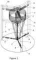
Figure 1 discloses a first embodiment of a tuned pendulum mass damper according to the invention. -
Figure 2 discloses the first embodiment in a side view. -
Figure 3 discloses the first embodiment seen from above. -
Figure 4 discloses a second embodiment of a tuned pendulum mass damper according to the invention. -
Figure 5 discloses the second embodiment in a side view. -
Figure 6 discloses the second embodiment seen from above. - Throughout the application identical or similar elements of different embodiments are given the same reference numbers.
- In general-when this expression is used in respect of a feature, the feature may be employed with any embodiment of the invention, even though the specific mentioning appears in the detailed part of the description.
- The present invention relates to a tuned pendulum mass damper according to
claim 1, such as an inverted pendulum mass damper which may be suspended. A pendulum mass damper is characterized by that the mass moves in a spherical plane which sphere, or spherical plane is defined by a central point C. - The natural frequency of an inverted pendulum according to the present invention is not determined by the length of the pendulum as the natural frequency of an ordinary pendulum, instead the natural frequency is influenced by a spring system stabilizing the horizontal position of the mass. This makes it possible to reduce the height of the tuned mass damper making the mass damper significantly more compact while the tuned mass damper may still be able to compensate for vibrations at low frequency.
- The pendulum mass damper according to the present invention should normally be installed in top of a building to perform optimally, and as a pendulum mass damper according to the invention requires minimum vertical space for installation, more space may be available on top floors compared to top floors of buildings where a traditional pendulum mass damper is installed. Contrary to a traditional gravity pendulum, the achievement of an aimed natural frequency does not necessarily involve varying the height of the mass damper. Instead, it can be obtained by adjusting damper mass and spring stiffness. Hence, pendulum dimensions may be maintained.
-
Figs. 1-3 illustrates a first embodiment of the invention where the mass of the pendulum is suspended, andfigs. 4-6 illustrates a second embodiment of the invention where the mass of the pendulum is supported by a rigid beam. - That the pendulum mass damper is suspended means that the weight of the mass of the damper is carried by a cable or a similar structure which extends from a level or point above the central point C and down to the central point C. I.e. the force keeping the mass at its vertical position is a tension or pulling force.
- An inverted pendulum mass damper according to the invention may consist of simple mechanical components and bolted connections requiring only minimal maintenance during the lifetime of the device at the position of installation.
-
Figs. 1-3 show a first embodiment of a pendulum mass damper according to the invention, wherefig. 1 shows an upper side view of the first embodiment,fig. 2 shows a side view of the same embodiment andfig. 3 shows a top view of the same embodiment. The pendulum mass damper comprises adamper mass 1 which is balanced horizontally by a first spring system comprising threesprings fig. 1 is of a cylindrical shape and consists of a series of smaller cylindrical masses, centrally drilled, which are installed and piled up on a vertical tube. However, thedamper mass 1 may have any shape e.g. cylindrical or spherical or different, and weight, as the shape and weight of the mass are adapted to the structure in which it is desired to damp vibrations. - The first spring system is normally constituted of one or more springs positioned above, below or at the same level as the
mass 1, the spring(s) of the first spring system provide a horizontal force balancing the mass and advantageously the spring(s) are mounted close to themass 1. That the springs are mounted "close" to themass 1 means that the length between the top of themass 1 and the fastening point or fastening level of the springs deviates less than 20%, e.g. less than 10% or e.g. less than 5%, from the total length of the pendulum measured from the central point C to the fastening points or fastening level of the springs. The fastening point or fastening level of the springs will normally be positioned at the top of the pendulum. - In general, the spring system may comprise any number of springs, e.g. the spring system may comprise at least two springs e.g. positioned opposite each other i.e. with a distance of 180° between the springs, or at least three springs i.e. with a distance of 120° between each pair of springs or at least four springs i.e. with a distance of at least 90° between each pair of springs. Also, the springs are shown as coil or helical springs, but in general, the springs of the spring system may be of any type of compression or tension springs. The complete spring system comprising the first 2a, 2b, 2c and second 8 spring system is aimed at providing the system with the right stiffness, and thus right natural frequency. Depending on the first spring system configuration the tuned pendulum mass damper can either be symmetric or not, meaning that the suspended inverted pendulum frequency may either be identical for any moving direction or may vary in a desired manner. This allows the pendulum mass damper to perform horizontally in two-dimensions for any direction of motion.
- Also, the springs are shown as being positioned horizontally, but in general, springs of the first spring system may be position in an inclined position, i.e. instead of providing a force in a horizontal direction, each or part of the springs of the first spring system may provide a force in both a horizontal and in a vertical direction.
- In general, a first spring system may comprise at least three springs or is at least connected to springs in three directions e.g. symmetrically distributed around the mass. The system may be provided with symmetric stiffness in all directions if the first spring system comprise of N springs, where N = 3*n, for n being a positive integer.
- If the first spring system comprises four springs or is balanced in four directions, the system will be stable, but the stiffness will not be symmetric.
- The pendulum mass damper in
fig. 1-3 is mounted in anexternal frame 6, theframe 6 is attached to or is part of a structure such as a high building or tower being subjected to vibrations which vibrations would cause the structure to oscillate if no damper is present, i.e. theframe 6 does not move but is stationary relative to the structure. The pendulum mass damper further comprises one or more support part(s) 3 which helps maintaining themass 1 in a vertical position, the support part(s) 3 are attached or fixed to themass 1 and extends between themass 1 and aunit 5 comprising a central point C being center of a sphere constituting a spherical plane in which themass 1 moves. Theunit 5 is positioned below themass 1 i.e. the weight of themass 1 is supported at a point/level below themass 1, and theunit 5 may be understood to constitute the base of a supporting system for themass 1. - In general, the
unit 5 may be constituted of a part of theframe 6, or alternatively, theunit 5 may be constituted of a separate floating part, such as a plate or another suitable shape, being attached to theframe 6 by flexible parts e.g. a second spring system. The central point C moves together with theunit 5 changing the spherical plane in which themass 1 moves. - According to the first embodiment, the
unit 5 is a floating part attached to theframe 6 by asecond spring system 8 whichsecond spring system 8 comprises 3 springs evenly distributed around theunit 5. The number of springs in the second spring system is not significant, but normally the springs of this spring system may be very stiff allowing very limited horizontal movement between theframe 6 and aunit 5 constituted of a floating part thereby maintaining tension between theunit 5 and theframe 6. - In general, a pendulum mass damper according to the invention may also comprise a central carrying
part 4 carrying themass 1 and being connected to a central point C. Such a central carryingpart 4 may be constituted of e.g. one or more cables or similar, or of a rigid beam. Thecentral carrying part 4 may comprisesupport parts 3 forming a connection between themass 1 and the central point C withoutsuch support parts 3 may comprise one or more rigid beams or similar part(s) extending from themass 1 to theunit 5. - The carrying
part 4 of the first embodiment is constituted of one or more cables or similar suspension means which suspension means are extending between asuspension frame 7 and theunit 5. According to the embodiment offig. 1-3 , thesuspension frame 7 comprises three beams which extend between a central point or a centrally positioned plate and theframe 6, and the carryingpart 4 comprises a cable extending from the central point or plate to theunit 5. - In general, the
unit 5 may comprise a joint having 1, 2 or 3 degrees of freedom i.e. the joint may allow themass 1 and the supportingparts 3 to pivot relative to theunit 5. Theunit 5 and the carryingpart 4 do not pivot as the second spring system will strive to maintain a constant horizontal and vertical position of theunit 5, whereas themass 1 and the supportingparts 3 pivot at least back and forth in one direction, possibly in two directions and possibly in three or more directions. -
Figs. 4-6 show a second embodiment of a pendulum mass damper according to the invention, wherefig. 4 shows an upper side view of the second embodiment,fig. 5 shows a side view of the second embodiment andfig. 6 shows a top view of the second embodiment. The pendulum mass damper comprises adamper mass 1 being balanced horizontally by a first spring system comprising threesprings fig. 4-6 is of a cylindrical shape and consists of a series of smaller cylindrical masses, centrally drilled, which are installed and piled up on a vertical tube. In general, thedamper mass 1 may have any shape e.g. cylindrical or spherical or different, and any weight, as the shape and weight of the mass are adapted to the structure in which it is desired to damp vibrations. - The pendulum mass damper in
fig. 4-6 is mounted in anexternal frame 6, whichframe 6 is attached to or is part of a structure such as a high building or tower being subjected to vibrations which vibrations would cause the structure to oscillate if no damper is present, i.e. the frame is stationary relative to the structure. The pendulum mass damper comprises a central carryingpart 4 attached or fixed to themass 1 and extending between themass 1 and theunit 5 comprising a central point C being center of a sphere constituting the spherical plane in which themass 1 moves. Theunit 5 is positioned below themass 1 i.e. the weight of themass 1 is supported at a point/level below themass 1, and theunit 5 may be understood to constitute the base of a supporting system for themass 1. Theunit 5 of the second embodiment may comprise a ball joint and the carryingpart 4 may then comprise a ball-shaped end part supported by this joint. In general, theunit 5 may comprise any joint allowing movement in all directions. - The
unit 5 may comprise a lower surface provided with wheels or other means adapted to slide over a contact surface of the structure or a frame fixed to the structure, and theunit 5 may be attached to aframe 6 of the structure by asecond spring system 8 as described in connection with the first embodiment. The stiffness configuration of thesecond spring system 8 is important for the performance of the damper according to this embodiment. The number of springs and the stiffness can be changed in the same way as the springs of the first spring system. - In general, the
unit 5 may comprise a joint having 1, 2 or 3 degrees of freedom i.e. the joint may allow themass 1 and the supportingparts 3 to pivot relative to theunit 5. - As the natural frequency of the system does not only depend on the length of the system but on a variety of different parameters the pendulum mass damper becomes versatile, and adoptable to damp the dynamic response of a variety of slender structures, such as high-rise buildings and wind turbine towers having a natural frequency within the range [0.05 ; 0.3] Hz (equivalent to a wire length of a traditional pendulum in the range [99 ; 2.8] m). This band represents only a sub-group of frequencies which the damper is meant for and the frequency can be regulated according to the application purpose.
- According to the theoretical model which the invention is based on, the pendulum mass damper according to the invention would, in principle, be capable of acting for infinitesimally small frequencies.
- When e.g. the wind-induced vibrations hit the natural frequency of the inverted pendulum, the
mass 1 starts to oscillate around the center C of theunit 5 placed at the base of the supporting system. The mass will either pivot around the point C or even further below.Ref. no. Ref. name 1 Mass 2a, 2b, 2c Spring system 3 Support parts supporting the mass 4 Central carrying part carrying the mass 5 Unit positioned below the carrying part 46 External frame for mass damper 7 Suspension frame for carrying part 48 Second spring system defining horizontal position of unit 5 C Point defining the center of a spherical plane in which the mass of the pendulum moves F Point or level at which the first spring system is fastened to central axis
Claims (12)
- A tuned pendulum mass damper for damping oscillations of a structure comprising a mass (1), a first spring system (2a, 2b, 2c) and a carrying part (4), said mass (1) being carried by the carrying part (4) to maintain a vertical position of the mass, the carrying part (4) carrying the mass (1) in the vertical direction extends between the mass (1) and a position (C) below the mass (1), i.e. the weight of the mass (1) is carried or supported from or at a point or level below the mass (1), wherein the mass (1) at the position (C) below the mass is fixed and/or
connected to a unit (5) constituting a base of a supporting system for the mass (1) which unit (5) is floating i.e. the unit (5) can move either horizontally or both horizontally and verticality , characterized in that said mass (1) being balanced by the first spring system (2a, 2b, 2c), - A pendulum mass damper according to claim 1, wherein the unit (5) is constituted of a floating part, such as a plate or another suitable shape, e.g. being balanced by flexible parts such as a second spring system (8).
- A pendulum mass damper according to any previous claim, wherein the carrying part (4) comprises a central carrying part (4) extending from a suspension frame (7) to the position (C).
- A pendulum mass damper according to any previous claim, wherein the first spring system (2a, 2b, 2c) balances the mass (1) horizontally and is positioned above, below or at approximately the same vertical level as the mass (1).
- A pendulum mass damper according to any previous claim, wherein the first spring system (2a, 2b, 2c) balances the mass (1) horizontally and is attached or fixed at the central axis above the vertical level of the mass (1) within a distance of the top of the mass being less than 20%, e.g. less than 10% or e.g. less than 5%, from the total length of the pendulum measured from the central point (C) to the fastening points or fastening level (F) of the springs.
- A pendulum mass damper according to any previous claim, wherein the first spring system (2a, 2b, 2c) comprises at least 3 springs or at least balances the mass in three directions.
- A pendulum mass damper according to any previous claim, the carrying part (4) comprises a central carrying part (4) in form of one or more cables or similar extending from a suspension frame (7) to the position (C), or in form of a rigid beam e.g. made of steel or similarly rigid material extending from the mass (1) to the position (C).
- A pendulum mass damper according to any previous claim, wherein the carrying part (4) also comprises support parts (3) e.g. in form of one or more rigid beams or similar part(s) extending from the mass (1) to the unit (5) positioned below the mass (1) which support part(s) may be resting on the unit (5).
- A pendulum mass damper according to any previous claim, wherein the unit (5) comprises a joint allowing either the support part(s) (3) or the carrying part(s) (4) to pivot relative to the unit (5).
- A pendulum mass damper according to claim 8, wherein the joint has 1, 2 or 3 degrees of freedom i.e. the joint may allow the mass (1) to pivot relative to the unit (5) in one, two or more than two directions.
- A structure comprising a pendulum mass damper according to any of the claims 1-10.
- A structure according to claim 11, wherein the structure is a building, wind turbine tower, chimney or other towers.
Applications Claiming Priority (2)
| Application Number | Priority Date | Filing Date | Title |
|---|---|---|---|
| DKPA201900632A DK180710B1 (en) | 2019-05-24 | 2019-05-24 | Pendulum mass damper |
| PCT/EP2020/064146 WO2020239590A1 (en) | 2019-05-24 | 2020-05-20 | Pendulum mass damper |
Publications (3)
| Publication Number | Publication Date |
|---|---|
| EP3976906A1 EP3976906A1 (en) | 2022-04-06 |
| EP3976906B1 true EP3976906B1 (en) | 2024-02-14 |
| EP3976906C0 EP3976906C0 (en) | 2024-02-14 |
Family
ID=70847367
Family Applications (1)
| Application Number | Title | Priority Date | Filing Date |
|---|---|---|---|
| EP20727981.1A Active EP3976906B1 (en) | 2019-05-24 | 2020-05-20 | Pendulum mass damper |
Country Status (6)
| Country | Link |
|---|---|
| US (1) | US20220228393A1 (en) |
| EP (1) | EP3976906B1 (en) |
| BR (1) | BR112021023508A2 (en) |
| DK (1) | DK180710B1 (en) |
| SG (1) | SG11202112465TA (en) |
| WO (1) | WO2020239590A1 (en) |
Families Citing this family (4)
| Publication number | Priority date | Publication date | Assignee | Title |
|---|---|---|---|---|
| ES2782195T3 (en) * | 2016-02-24 | 2020-09-11 | Fm Energie Gmbh & Co Kg | Wind turbines with elastic pendulum ball bearings |
| CN113007033A (en) * | 2021-03-02 | 2021-06-22 | 中国大唐集团新能源科学技术研究院有限公司 | Wind generating set with main shaft internally provided with tuning damping device |
| CN113513103B (en) * | 2021-09-14 | 2021-12-17 | 中国电建集团山东电力建设第一工程有限公司 | Suspension type composite tuning vibration reduction device and method |
| CN113738818B (en) * | 2021-11-03 | 2022-02-08 | 溧阳常大技术转移中心有限公司 | Two-dimensional vibration isolator capable of exciting and isolating any displacement in opposite surface |
Citations (8)
| Publication number | Priority date | Publication date | Assignee | Title |
|---|---|---|---|---|
| JPH0512791U (en) * | 1991-08-02 | 1993-02-19 | 日本電信電話株式会社 | Inverted pendulum type vibration control device |
| JPH0656534U (en) * | 1993-01-13 | 1994-08-05 | 住友重機械工業株式会社 | Inverted pendulum type vibration control device |
| JPH0754520A (en) * | 1993-08-12 | 1995-02-28 | Nippon Steel Corp | Damping device for structure |
| JPH1136664A (en) * | 1997-07-17 | 1999-02-09 | Showa Electric Wire & Cable Co Ltd | Dynamic vibration reducer |
| JP2001349094A (en) * | 2000-06-08 | 2001-12-21 | Sekisui House Ltd | Synchronous pendulum type vibration control device |
| JP2011069104A (en) * | 2009-09-25 | 2011-04-07 | Tatsuji Ishimaru | Seismic control device and seismic control structure |
| JP2013245765A (en) * | 2012-05-25 | 2013-12-09 | Tokkyokiki Corp | Mass damper type vibration control device |
| US20170328058A1 (en) * | 2014-12-05 | 2017-11-16 | Esm Energie-Und Schwingungstechnik Mitsch Gmbh | Adaptive oscillation damper having a vertical spring mechanism |
Family Cites Families (6)
| Publication number | Priority date | Publication date | Assignee | Title |
|---|---|---|---|---|
| US1761322A (en) * | 1928-04-09 | 1930-06-03 | George W Anderson | Foundation construction |
| NZ238798A (en) * | 1990-08-30 | 1993-11-25 | Mitsubishi Heavy Ind Ltd | Low height long period pendulum damping equipment for tall buildings |
| US5915508A (en) * | 1994-04-18 | 1999-06-29 | Minnesota Mining And Manufacturing Company | Tuned mass damper |
| FR2749901B1 (en) * | 1996-06-12 | 2000-12-08 | Eurocopter France | DEVICE FOR REDUCING THE VIBRATION GENERATED BY A LIFT ROTOR OF A TURNED AIRCRAFT |
| US20010032420A1 (en) * | 2000-01-25 | 2001-10-25 | Ma-Chi Chen | Gravity balance frame |
| CN102893052A (en) * | 2011-04-22 | 2013-01-23 | 三菱重工业株式会社 | Vibration-damping device, wind turbine device, and vibration-damping method |
-
2019
- 2019-05-24 DK DKPA201900632A patent/DK180710B1/en active IP Right Grant
-
2020
- 2020-05-20 SG SG11202112465TA patent/SG11202112465TA/en unknown
- 2020-05-20 EP EP20727981.1A patent/EP3976906B1/en active Active
- 2020-05-20 US US17/612,307 patent/US20220228393A1/en active Pending
- 2020-05-20 WO PCT/EP2020/064146 patent/WO2020239590A1/en unknown
- 2020-05-20 BR BR112021023508A patent/BR112021023508A2/en unknown
Patent Citations (8)
| Publication number | Priority date | Publication date | Assignee | Title |
|---|---|---|---|---|
| JPH0512791U (en) * | 1991-08-02 | 1993-02-19 | 日本電信電話株式会社 | Inverted pendulum type vibration control device |
| JPH0656534U (en) * | 1993-01-13 | 1994-08-05 | 住友重機械工業株式会社 | Inverted pendulum type vibration control device |
| JPH0754520A (en) * | 1993-08-12 | 1995-02-28 | Nippon Steel Corp | Damping device for structure |
| JPH1136664A (en) * | 1997-07-17 | 1999-02-09 | Showa Electric Wire & Cable Co Ltd | Dynamic vibration reducer |
| JP2001349094A (en) * | 2000-06-08 | 2001-12-21 | Sekisui House Ltd | Synchronous pendulum type vibration control device |
| JP2011069104A (en) * | 2009-09-25 | 2011-04-07 | Tatsuji Ishimaru | Seismic control device and seismic control structure |
| JP2013245765A (en) * | 2012-05-25 | 2013-12-09 | Tokkyokiki Corp | Mass damper type vibration control device |
| US20170328058A1 (en) * | 2014-12-05 | 2017-11-16 | Esm Energie-Und Schwingungstechnik Mitsch Gmbh | Adaptive oscillation damper having a vertical spring mechanism |
Also Published As
| Publication number | Publication date |
|---|---|
| SG11202112465TA (en) | 2021-12-30 |
| US20220228393A1 (en) | 2022-07-21 |
| WO2020239590A1 (en) | 2020-12-03 |
| DK201900632A1 (en) | 2021-02-18 |
| DK180710B1 (en) | 2021-12-16 |
| BR112021023508A2 (en) | 2022-01-18 |
| EP3976906A1 (en) | 2022-04-06 |
| EP3976906C0 (en) | 2024-02-14 |
| CN113924400A (en) | 2022-01-11 |
Similar Documents
| Publication | Publication Date | Title |
|---|---|---|
| EP3976906B1 (en) | Pendulum mass damper | |
| US20190249740A1 (en) | Ultra-low frequency tuned liquid mass damper and design method of the same | |
| EP2195529A2 (en) | Windturbine support tower with pendulum-damping means | |
| JPH05501441A (en) | vibration isolation system | |
| KR20190135525A (en) | Vibration damping of wind turbine tower | |
| US4700817A (en) | Dynamic vibration absorber with spring-supported pendulum | |
| KR20210025099A (en) | Tower damper | |
| US4875313A (en) | Device for suppressing vibration of structure | |
| KR102507353B1 (en) | Small space ellipsoidal mass pendulum | |
| CN109577361A (en) | Frequency damp adjustable two-freedom universal horizontal vibration damping tuned mass damper | |
| JP2008190645A (en) | Vibration reducing mechanism and its specification setting method | |
| CN113924400B (en) | Pendulum mass damper and structure comprising a pendulum mass damper | |
| WO2004003306A1 (en) | Simple pendulum with variable restoring force | |
| JPH0310817B2 (en) | ||
| CN209620080U (en) | A kind of universal vibration tuned mass damper of spherical linkage formula ultralow frequency | |
| WO1992002743A1 (en) | Vibration-damping apparatus | |
| RU2096565C1 (en) | Dynamic oscillation dampener | |
| JPH0228746B2 (en) | FURIKOSHIKIDOKYUSHINKI | |
| CN209603169U (en) | Frequency damp adjustable two-freedom universal horizontal vibration damping tuned mass damper | |
| JP3068302B2 (en) | Pendulum damping device | |
| JPH02282584A (en) | Connection type double pendulum water tank damper | |
| EP4145012A1 (en) | Vibration damper | |
| CN209620079U (en) | A kind of universal vibration tuned mass damper of ball bearing formula ultra-low-frequency horizontal | |
| JPH0314094B2 (en) | ||
| UA58826A (en) | Ball damper of forced vibrations with linear-viscous resistance |
Legal Events
| Date | Code | Title | Description |
|---|---|---|---|
| STAA | Information on the status of an ep patent application or granted ep patent |
Free format text: STATUS: UNKNOWN |
|
| STAA | Information on the status of an ep patent application or granted ep patent |
Free format text: STATUS: THE INTERNATIONAL PUBLICATION HAS BEEN MADE |
|
| PUAI | Public reference made under article 153(3) epc to a published international application that has entered the european phase |
Free format text: ORIGINAL CODE: 0009012 |
|
| STAA | Information on the status of an ep patent application or granted ep patent |
Free format text: STATUS: REQUEST FOR EXAMINATION WAS MADE |
|
| 17P | Request for examination filed |
Effective date: 20220103 |
|
| AK | Designated contracting states |
Kind code of ref document: A1 Designated state(s): AL AT BE BG CH CY CZ DE DK EE ES FI FR GB GR HR HU IE IS IT LI LT LU LV MC MK MT NL NO PL PT RO RS SE SI SK SM TR |
|
| RIN1 | Information on inventor provided before grant (corrected) |
Inventor name: HANSEN, SVEND OLE |
|
| DAV | Request for validation of the european patent (deleted) | ||
| DAX | Request for extension of the european patent (deleted) | ||
| GRAP | Despatch of communication of intention to grant a patent |
Free format text: ORIGINAL CODE: EPIDOSNIGR1 |
|
| STAA | Information on the status of an ep patent application or granted ep patent |
Free format text: STATUS: GRANT OF PATENT IS INTENDED |
|
| INTG | Intention to grant announced |
Effective date: 20230829 |
|
| GRAS | Grant fee paid |
Free format text: ORIGINAL CODE: EPIDOSNIGR3 |
|
| GRAA | (expected) grant |
Free format text: ORIGINAL CODE: 0009210 |
|
| STAA | Information on the status of an ep patent application or granted ep patent |
Free format text: STATUS: THE PATENT HAS BEEN GRANTED |
|
| AK | Designated contracting states |
Kind code of ref document: B1 Designated state(s): AL AT BE BG CH CY CZ DE DK EE ES FI FR GB GR HR HU IE IS IT LI LT LU LV MC MK MT NL NO PL PT RO RS SE SI SK SM TR |
|
| REG | Reference to a national code |
Ref country code: GB Ref legal event code: FG4D |
|
| REG | Reference to a national code |
Ref country code: CH Ref legal event code: EP |
|
| REG | Reference to a national code |
Ref country code: DE Ref legal event code: R096 Ref document number: 602020025670 Country of ref document: DE |
|
| REG | Reference to a national code |
Ref country code: IE Ref legal event code: FG4D |
|
| U01 | Request for unitary effect filed |
Effective date: 20240311 |
|
| U07 | Unitary effect registered |
Designated state(s): AT BE BG DE DK EE FI FR IT LT LU LV MT NL PT SE SI Effective date: 20240319 |