JP2011069104A - Seismic control device and seismic control structure - Google Patents
Seismic control device and seismic control structure Download PDFInfo
- Publication number
- JP2011069104A JP2011069104A JP2009220789A JP2009220789A JP2011069104A JP 2011069104 A JP2011069104 A JP 2011069104A JP 2009220789 A JP2009220789 A JP 2009220789A JP 2009220789 A JP2009220789 A JP 2009220789A JP 2011069104 A JP2011069104 A JP 2011069104A
- Authority
- JP
- Japan
- Prior art keywords
- vibration
- additional mass
- moving
- rotating body
- rotating
- Prior art date
- Legal status (The legal status is an assumption and is not a legal conclusion. Google has not performed a legal analysis and makes no representation as to the accuracy of the status listed.)
- Pending
Links
Images


Landscapes
- Building Environments (AREA)
- Buildings Adapted To Withstand Abnormal External Influences (AREA)
- Vibration Prevention Devices (AREA)
Abstract
【課題】層間変位によって付加質量体が回転する構成と比較し設置の制限を少なくする。
【解決手段】付加質量体170を回転させることで得られる回転慣性質量は、付加質量体170との実際の質量よりも大きな付加質量体を付加したことと等価となり、付加質量体170を回転させない構成と比較し、大きな振動低減効果が得られる。また、層間変位によって付加質量体が回転する構成と比較し、設置の制限が少なく、しかも、付加質量体を回転させない一般的なTMDと比較し、鉛直方向の振動に対する大きな制震効果が得られる。
【選択図】図1An installation mass is reduced as compared with a configuration in which an additional mass body rotates due to interlayer displacement.
Rotational inertial mass obtained by rotating an additional mass body is equivalent to adding an additional mass body larger than the actual mass with the additional mass body, and the additional mass body is not rotated. Compared with the configuration, a large vibration reduction effect can be obtained. In addition, compared to a configuration in which the additional mass body rotates due to interlayer displacement, there are fewer installation restrictions, and a greater vibration control effect on vertical vibration can be obtained compared to a general TMD that does not rotate the additional mass body. .
[Selection] Figure 1
Description
本発明は、制震装置及び制震構造物に関する。 The present invention relates to a vibration control device and a vibration control structure.
構造物の振動を低減するための機構として、特許文献1に示されている所謂チューンドマスダンパー(Tuned Mass Damper:TMD)が知られている。チューンドマスダンパー(TMD)は、構造物に付加バネを介して付加質量体を接続し、付加バネと付加質量体とにより定まる固有振動数を構造物の固有振動数に同調させることにより、構造物の共振点近傍における応答を低減するものとされている(特許文献1を参照)。
As a mechanism for reducing the vibration of the structure, a so-called tuned mass damper (TMD) disclosed in
また、特許文献2には、多層構造物の任意の層に、層間変形によって錘が回転し回転慣性質量を生じる回転慣性質量ダンパーを設置すると共に、該回転慣性質量ダンパーと直列に付加バネを設置し、回転慣性質量と付加バネとにより定まる固有振動数を、構造物の固有振動数に同調させることによって、この固有振動数における構造物の応答を低減させる振動低減機構が提案されている(特許文献2を参照)。
Also, in
しかし、一般的なチューンドマスダンパー(TMD)における付加質量体は、制震対象の構造物と比較すると質量が小さく、付加質量体の構造物に対する質量比μは非常に小さい(付加質量体の質量は構造物の1%以下となることが多い)。このため、一般的には、チューンドマスダンパーは風力等による微振動の制震に対しては効果的であるが、地震などの大きな振動の制震には十分効果が得られないとされている。 However, the additional mass body in a general tuned mass damper (TMD) has a smaller mass than the structure to be controlled, and the mass ratio μ of the additional mass body to the structure is very small (the mass of the additional mass body). Is often less than 1% of the structure). For this reason, tuned mass dampers are generally effective for controlling fine vibrations caused by wind power, etc., but are not sufficiently effective for controlling large vibrations such as earthquakes. .
また、特許文献2の振動低減機構(制震装置)は、層間変形、例えば、層を構成する上下の構造床(スラブ)の水平方向の相対変位によって錘(付加質量体)が回転するので、層を構成する上下の構造床に、直列に配置された回転慣性質量ダンパーと付加バネとを接続する必要がある。よって、設置場所や設置方法等の設置制限が大きい。
Further, the vibration reduction mechanism (damping device) of
本発明は、上記を考慮し、層間変位によって付加質量体が回転する構成と比較し、設置の制限が少ない制震装置及び該制震装置を備える制震構造物を提供することが目的である。 In view of the above, an object of the present invention is to provide a vibration control device and a vibration control structure including the vibration control device with less restrictions on installation compared to a configuration in which an additional mass body rotates due to interlayer displacement. .
請求項1の発明は、移動体と構造床とに接続され、鉛直方向に弾性変形する弾性部材と、前記構造床に設けられ、前記移動体の鉛直方向の変位を付加質量体の回転運動に変換する回転機構部と、を備え、前記移動体の鉛直方向の振動の固有振動が、前記構造床の鉛直方向の振動の固有振動に同調するように設定されている。
The invention according to
請求項1の発明では、移動体の鉛直方向の振動の固有振動数が、構造床の鉛直方向の振動の固有振動数に同調するように設定されることで、外乱によって生じる構造床の鉛直方向の振動が低減される。 In the first aspect of the present invention, the natural frequency of the vertical vibration of the moving body is set so as to be synchronized with the natural frequency of the vertical vibration of the structural floor, so that the vertical direction of the structural floor caused by the disturbance Vibration is reduced.
このとき、移動体の鉛直方向の変位が付加質量体の回転運動に変換されること、すなわち、付加質量体が回転することで得られる回転慣性質量は、付加質量体の実際の質量よりも大きな付加質量体を付加したことと等価となり、付加質量体を回転させない構成と比較し、大きな振動低減効果が得られる。言いかえると、付加質量体を回転させない構成と比較し、大きな制震効果が得られる。 At this time, the vertical displacement of the moving body is converted into the rotational motion of the additional mass body, that is, the rotational inertial mass obtained by the rotation of the additional mass body is larger than the actual mass of the additional mass body. This is equivalent to the addition of the additional mass body, and a large vibration reduction effect can be obtained as compared with the configuration in which the additional mass body is not rotated. In other words, a greater seismic control effect can be obtained compared to a configuration in which the additional mass is not rotated.
また、本制震装置は、弾性部材によって支持された移動体の鉛直方向の振動によって、付加質量体が回転し回転慣性質量が発生する。よって、層間変位によって付加質量体が回転する構成と比較し、設置の制限が少ない。 Further, in the present vibration damping device, the additional mass body is rotated by the vertical vibration of the moving body supported by the elastic member, and a rotational inertial mass is generated. Therefore, there are few installation restrictions compared with the structure which an additional mass body rotates by interlayer displacement.
請求項2の発明は、前記移動体の振動を減衰させる減衰部材を有する。
The invention of
請求項2の発明では、減衰部材によって、移動体の振動が早期に収束される。
In the invention of
請求項3の発明は、前記移動体は、鉛直方向を軸方向として配置された軸体を有し、前記回転機構部は、前記軸体が挿入される回転体と、前記構造床に設けられ、前記回転体を回転可能に保持する保持体と、前記軸体の外周面と前記回転体の内周面とに設けられ、前記軸体の軸方向の直線運動を前記回転体の軸周りの回転運動に変換する螺合手段と、前記回転体と一体となって軸周りに回転する前記付加質量体と、を有する。 According to a third aspect of the present invention, the movable body has a shaft body arranged with the vertical direction as an axial direction, and the rotating mechanism is provided on the rotating body into which the shaft body is inserted and the structural floor. And a holding body for rotatably holding the rotating body, and an outer peripheral surface of the shaft body and an inner peripheral surface of the rotating body, and the linear motion in the axial direction of the shaft body around the axis of the rotating body. A screwing means for converting to a rotational motion; and the additional mass body integrally rotating with the rotating body and rotating about an axis.
請求項3の発明では、移動体が鉛直方向に変位することによって、軸体が鉛直方向に変位する。そして、軸体の外周面と回転体の内周面に設けられた螺合手段によって、軸体の鉛直方向の変位が回転体及び付加質量体の回転運動に変換される。
In the invention of
実際に得られる回転慣性質量は、付加質量体と回転体との合計となるが、ここでは便宜上、回転体の回転質量は無視して説明している。 The rotational inertia mass actually obtained is the sum of the additional mass body and the rotating body, but here, for convenience, the rotating mass of the rotating body is ignored.
なお、回転体と付加質量体とが一体となった構成であってもよい。或いは、回転体と保持体(又は保持体の一部)とが一体となった構成であってもよい。 The rotating body and the additional mass body may be integrated. Alternatively, the rotating body and the holding body (or a part of the holding body) may be integrated.
請求項4の発明は、前記移動体は、並列に配置された複数の前記軸体を有し、前記回転機構部が、前記軸体毎に複数備えられている。 According to a fourth aspect of the present invention, the moving body includes a plurality of the shaft bodies arranged in parallel, and a plurality of the rotation mechanism sections are provided for each of the shaft bodies.
請求項4の発明では、一つの移動体が鉛直方向に変位すると、並列に配置された複数の軸体に対応する複数の付加質量体が回転するので、より大きな回転慣性質量が得られる。また、軸体は並列に配置されているので、制震装置の軸方向の全長が長くならない。つまり、制震装置の軸方向の全長が長くなることなく、大きな回転慣性質量が得られる。
In the invention of
請求項5の発明は、移動体と構造床とに接続され、水平方向に弾性変形する弾性部材と、前記構造床に設けられ、前記移動体の水平方向の変位を付加質量体の回転運動に変換する回転機構部と、を備え、前記移動体の水平方向の振動の固有振動が、前記構造床の水平方向の振動の固有振動に同調するように設定されている。 According to a fifth aspect of the present invention, there is provided an elastic member that is connected to the moving body and the structural floor and elastically deforms in a horizontal direction, and is provided on the structural floor. A rotating mechanism unit for converting, and the natural vibration of the horizontal vibration of the movable body is set to synchronize with the natural vibration of the horizontal vibration of the structural floor.
請求項5の発明では、移動体の水平方向の振動の固有振動数が、構造床の水平方向の振動の固有振動数に同調するように設定されることで、外乱によって生じる構造床の水平方向の振動が低減される。
In the invention of
このとき、移動体の水平方向の変位が付加質量体の回転運動に変換されること、すなわち、付加質量体が回転することに得られる回転慣性質量は、付加質量体の実際の質量よりも大きな付加質量体を付加したことと等価となり、付加質量体を回転させない構成と比較し、大きな振動低減効果が得られる。言いかえると付加質量体を回転させない構成と比較し、大きな制震効果が得られる。 At this time, the horizontal displacement of the moving body is converted into the rotational motion of the additional mass body, that is, the rotational inertial mass obtained by the rotation of the additional mass body is larger than the actual mass of the additional mass body. This is equivalent to the addition of the additional mass body, and a large vibration reduction effect can be obtained as compared with the configuration in which the additional mass body is not rotated. In other words, a greater seismic control effect can be obtained compared to a configuration in which the additional mass is not rotated.
なお、本制震装置は、移動体の水平方向の振動によって、付加質量体が回転し回転慣性質量が発生する。よって、例えば、層間変位によって付加質量体が回転する構成と比較し、設置の制限が少ない。 In the present vibration damping device, the additional mass body is rotated by the horizontal vibration of the moving body to generate a rotational inertial mass. Therefore, for example, there are few installation restrictions compared with the structure which an additional mass body rotates by interlayer displacement.
請求項6の発明は、前記移動体の振動を減衰させる減衰部材を有する。
The invention of
請求項6の発明では、減衰部材によって、移動体の振動が早期に収束される。
In the invention of
請求項7の発明は、前記移動体は、水平方向を軸方向として配置された軸体を有し、前記回転機構部は、前記軸体が挿入される回転体と、前記構造床に設けられ、前記回転体を回転可能に保持する保持体と、前記軸体の外周面と前記回転体の内周面とに設けられ、前記軸体の軸方向の直線運動を前記回転体の軸周りの回転運動に変換する螺合手段と、前記回転体と一体となって軸周りに回転する前記付加質量体と、を有する。 According to a seventh aspect of the present invention, the movable body has a shaft body arranged with the horizontal direction as an axial direction, and the rotation mechanism section is provided on the rotating body into which the shaft body is inserted and the structural floor. And a holding body for rotatably holding the rotating body, and an outer peripheral surface of the shaft body and an inner peripheral surface of the rotating body, and the linear motion in the axial direction of the shaft body around the axis of the rotating body. A screwing means for converting to a rotational motion; and the additional mass body integrally rotating with the rotating body and rotating about an axis.
請求項7の発明では、移動体が水平方向に変位することによって、軸体が水平方向に変位する。そして、軸体の外周面と回転体の内周面に設けられた螺合手段によって、軸体の鉛直方向の変位が回転体及び付加質量体の回転運動に変換される。 In the seventh aspect of the invention, the movable body is displaced in the horizontal direction, so that the shaft body is displaced in the horizontal direction. Then, the vertical displacement of the shaft body is converted into the rotational motion of the rotating body and the additional mass body by screwing means provided on the outer peripheral surface of the shaft body and the inner peripheral surface of the rotating body.
実際に得られる回転慣性質量は、付加質量体と回転体との合計となるが、ここでは便宜上、回転体の回転質量は無視して説明している。 The rotational inertia mass actually obtained is the sum of the additional mass body and the rotating body, but here, for convenience, the rotating mass of the rotating body is ignored.
なお、回転体と付加質量体とが一体となった構成であってもよい。或いは、回転体と保持体(又は保持体の一部)とが一体となった構成であってもよい。 The rotating body and the additional mass body may be integrated. Alternatively, the rotating body and the holding body (or a part of the holding body) may be integrated.
請求項8の発明は、前記移動体は、前記構造床に水平方向に間隔をあけて設けられた一対の第一移動部及び第二移動部と、前記第一移動部と前記第二移動部とに接合された前記軸体と、を有し、前記弾性部材は、前記第一移動部と前記構造床との間に設けられた第一弾性部材と、前記第二移動部と前記構造床との間に設けられた第二弾性部材と、を有し、記第一移動部と前記第二移動部との間に一つ又は複数の前記保持部が設けられ、保持部の軸方向両外側にそれぞれ前記付加質量体が設けられている。 According to an eighth aspect of the present invention, the moving body includes a pair of first moving portion and second moving portion, the first moving portion, and the second moving portion that are provided on the structural floor with a space in the horizontal direction. And the elastic member includes a first elastic member provided between the first moving part and the structural floor, the second moving part, and the structural floor. A second elastic member provided between the first moving part and the second moving part, wherein one or more holding parts are provided between the first moving part and the second moving part. The additional mass bodies are respectively provided on the outer sides.
請求項8の発明では、第一移動部及び第二移動部がそれぞれ、構造床との間に設けられた第一弾性部材及び第二弾性部材で接合されている。第一移動部及び第二移動部は、水平方向を軸方向として配置された軸体で接合されている。よって、第一移動部、第二移動部及び軸体が一体となって水平方向に振動する。また、第一移動部と第二移動部の間の保持部の軸方向両外側にそれぞれ設けられた付加質量体が回転し、回転慣性質量を発生させる。
In invention of
したがって、より大きな回転慣性質量が得られる。また、第一移動部と第二移動部の間に保持部が設けられ、軸体が支えられているので、軸体の軸方向の全長を長くしても、軸体の湾曲が抑制される。 Therefore, a larger rotational inertial mass is obtained. In addition, since the holding portion is provided between the first moving portion and the second moving portion and the shaft body is supported, the bending of the shaft body is suppressed even if the axial length of the shaft body is increased. .
請求項9の発明は、前記移動体は、並列に配置された複数の前記軸体を有し、前記回転機構部が、前記軸体毎に複数備えられている。 According to a ninth aspect of the present invention, the moving body includes a plurality of the shaft bodies arranged in parallel, and a plurality of the rotation mechanism sections are provided for each of the shaft bodies.
請求項9の発明では、一つの移動体が鉛直方向に変位すると、並列に配置された軸体に対応する回転機構部の付加質量体が回転するので、より大きな回転慣性質量が得られる。また、軸体は並列に配置されているので、制震装置の軸方向の全長が長くならない。つまり、制震装置の軸方向の全長が長くなることなく、大きな回転慣性質量が得られる。 According to the ninth aspect of the present invention, when one movable body is displaced in the vertical direction, the additional mass body of the rotation mechanism unit corresponding to the shaft bodies arranged in parallel rotates, so that a larger rotational inertial mass can be obtained. Moreover, since the shaft bodies are arranged in parallel, the total length in the axial direction of the vibration control device does not increase. That is, a large rotational inertial mass can be obtained without increasing the overall axial length of the vibration control device.
請求項10の発明は、前記付加質量体が回転を開始する際に、前記付加質量体が回転する方向に回転力を付与する回転力付与手段を有する。 According to a tenth aspect of the present invention, there is provided a rotational force applying means for applying a rotational force in a direction in which the additional mass body rotates when the additional mass body starts to rotate.
請求項10の発明では、付加質量体が回転を開始するためには、種々の抵抗力によって閾値以上の力が必要とされる。このため、外乱によって移動体が変位しようとしても、閾値を越える力が発生するまで、付加質量体は回転を開始しない。
In the invention of
よって、付加質量体が回転を開始する際に回転力付与手段によって付加質量体が回転する方向に回転力を付与することによって、外乱が発生してから付加質量体が回転を開始するまでの時間が短くなる。 Therefore, when the additional mass body starts rotating, the rotational force is applied in the direction in which the additional mass body rotates by the rotational force applying means, so that the time from when the disturbance occurs to when the additional mass body starts rotating is increased. Becomes shorter.
或いは、閾値を越えない程度(付加質量体が回転しない程度)の外乱であっても、付加質量体が回転を開始し、制震効果が得られる。 Alternatively, even if the disturbance does not exceed the threshold value (so that the additional mass body does not rotate), the additional mass body starts rotating, and a vibration control effect is obtained.
請求項11の発明は、前記付加質量体が回転を開始する際に、前記付加質量体が回転する方向に回転力を付与する回転力付与手段を有し、回転力付与手段は、前記回転体の回転駆動させる駆動手段と、前記軸体に作用する軸方向の圧力を検知する圧力検知手段と、前記圧力検知手段で検知された圧力値に基づいて、前記回転体を回転駆動させる回転方向を決定し、前記駆動手段を制御して決定された回転方向に前記回転体を回転駆動させる制御手段と、を有する。 The invention according to claim 11 has a rotational force applying means for applying a rotational force in a direction in which the additional mass body rotates when the additional mass body starts to rotate. Driving means for rotationally driving, pressure detecting means for detecting axial pressure acting on the shaft body, and a rotational direction for rotationally driving the rotating body based on the pressure value detected by the pressure detecting means. Control means for determining and controlling the driving means to rotationally drive the rotating body in the determined rotation direction.
請求項11の発明では、回転力の付与を開始するタイミングと、回転方向と、が容易に決定される。 In the invention of claim 11, the timing for starting the application of the rotational force and the rotation direction are easily determined.
例えば、軸体に作用する軸方向の圧力値が、外乱が作用していない状態よりも大きくなると又は所定値よりも大きくなると、正回転方向に(例えば時計回りに)付加質量体(回転体)に回転力を付与し、外乱が作用していない状態よりも小さくなると又は所定値よりも小さくなると、逆回転方向に(例えば反時計回りに)付加質量体(回転体)に回転力を付与する。 For example, when the pressure value in the axial direction acting on the shaft body becomes larger than a state in which no disturbance is applied or becomes larger than a predetermined value, the additional mass body (rotating body) in the positive rotation direction (for example, clockwise) When a rotational force is applied to the motor and the torque becomes smaller than a state in which no disturbance is applied or becomes smaller than a predetermined value, the rotational force is applied to the additional mass body (rotary body) in the reverse rotational direction (for example, counterclockwise). .
請求項12の発明は、前記回転力付与手段は、前記回転体の回転速度を検知する回転速度検知手段を有し、前記制御手段は、前記圧力検知手段で検知された圧力値と、前記回転速度検知手段で検知された回転速度値と、に基づいて前記回転体に付与する回転力を算出すると共に、算出結果に基づいて前記駆動手段の回転力を制御する。 According to a twelfth aspect of the present invention, the rotational force applying means includes a rotational speed detecting means for detecting a rotational speed of the rotating body, and the control means includes the pressure value detected by the pressure detecting means, and the rotation. Based on the rotational speed value detected by the speed detecting means, the rotational force applied to the rotating body is calculated, and the rotational force of the driving means is controlled based on the calculation result.
請求項12の発明では、回転体に付与される回転力が最適化又は略最適化される。
In the invention of
つまり、圧力検知手段で検知された圧力値が大きく、回転体の回転速度が遅い場合は、大きな回転力が回転体に付与され、圧力検知手段で検知された圧力値が小さく、回転体の回転速度が速い場合は、小さな回転力が回転体に付与される。 In other words, when the pressure value detected by the pressure detection means is large and the rotational speed of the rotating body is slow, a large rotational force is applied to the rotating body, the pressure value detected by the pressure detecting means is small, and the rotating body rotates. When the speed is high, a small rotational force is applied to the rotating body.
請求項13の発明は、請求項1〜請求項12のいずれか1項に記載の制震装置を備える。 A thirteenth aspect of the invention includes the vibration control device according to any one of the first to twelfth aspects.
請求項13の発明では、請求項1〜請求項12のいずれか1項に記載の制震装置を備えていない構造物と比較し、地震などによる振動が低減される。 In invention of Claim 13, the vibration by an earthquake etc. is reduced compared with the structure which is not equipped with the damping device of any one of Claims 1-12.
なお、請求項1〜請求項4のいずれか1項の制震装置と、請求項5〜請求項8のいずれか1項の制震装置と、の両方を備える構成の場合、制震対象の構造物における鉛直方向の振動と水平方向の振動の両方が低減される。 In addition, in the case of the structure provided with both the damping device of any one of Claims 1-4, and the damping device of any one of Claims 5-8, it is the object of damping control. Both vertical and horizontal vibrations in the structure are reduced.
請求項1に記載の発明によれば、層間変位によって付加質量体が回転する構成と比較して設置の制限が少ない。 According to the first aspect of the present invention, there are few installation restrictions compared to the configuration in which the additional mass body rotates due to the interlayer displacement.
請求項2に記載の発明によれば、減衰部材を有しない構成と比較し、移動体の振動が早期に収束される。
According to invention of
請求項3に記載の発明によれば、軸体の外周面と回転体の内周面に設けられた螺合手段によって、軸体の水平方向の変位が回転体及び付加質量体の回転運動に変換する。 According to the third aspect of the present invention, the horizontal displacement of the shaft body is caused by the rotational movement of the rotating body and the additional mass body by the screwing means provided on the outer peripheral surface of the shaft body and the inner peripheral surface of the rotating body. Convert.
請求項4に記載の発明によれば、制震装置の軸体の軸方向の全長を長くすることなく、大きな回転慣性質量を得ることができる。 According to the fourth aspect of the present invention, a large rotational inertial mass can be obtained without increasing the total axial length of the shaft body of the vibration control device.
請求項5に記載の発明によれば、層間変位によって付加質量体が回転する構成と比較し、設置の制限が少ない。
According to the invention described in
請求項6に記載の発明によれば、減衰部材を有しない構成と比較し、移動体の振動が早期に収束される。 According to the sixth aspect of the present invention, the vibration of the moving body is converged at an early stage as compared with the configuration having no damping member.
請求項7に記載の発明によれば、軸体の外周面と回転体の内周面に設けられた螺合手段によって、軸体の水平方向の変位が回転体及び付加質量体の回転運動に変換する。 According to the seventh aspect of the present invention, the horizontal displacement of the shaft body is caused by the rotational movement of the rotating body and the additional mass body by the screwing means provided on the outer peripheral surface of the shaft body and the inner peripheral surface of the rotating body. Convert.
請求項8に記載の発明によれば、軸体の長さを長くして複数の付加質量体を設けても、軸体の湾曲を抑制することができる。 According to the eighth aspect of the invention, even if the length of the shaft body is increased and a plurality of additional mass bodies are provided, the bending of the shaft body can be suppressed.
請求項9に記載の発明によれば、制震装置の軸体の軸方向の全長を長くすることなく、大きな回転慣性質量を得ることができる。 According to the ninth aspect of the present invention, a large rotational inertial mass can be obtained without increasing the total axial length of the shaft body of the vibration control device.
請求項10に記載の発明によれば、外乱が発生してから付加質量体が回転を開始するまでの時間を短くすることができる。或いは、付加質量体が回転するために必要な力が得られない程度(付加質量体が回転しない程度)の外乱であっても、付加質量体が回転を開始し、制震効果を得ることができる。
According to the invention described in
請求項11に記載の発明によれば、回転力の付与を開始するタイミングと、回転方向と、を容易に決定することができる。 According to the eleventh aspect of the present invention, it is possible to easily determine the timing for starting the application of the rotational force and the rotation direction.
請求項12に記載の発明によれば、回転体に付与する回転力が容易に最適化又は略最適化することができる。 According to the twelfth aspect of the present invention, the rotational force applied to the rotating body can be easily optimized or substantially optimized.
請求項13に記載の発明によれば、請求項1〜請求項12のいずれか1項に記載の制震装置を備えていない構造物と比較し、地震などによる振動を低減することができる。
According to the invention described in claim 13, it is possible to reduce vibration due to an earthquake or the like as compared with a structure that does not include the vibration control device according to any one of
なお、本発明において「同調させる」とは、完全に周期が同調する場合に限定されない。設計上、固有周期の同調が多少ずれていても、振動低減効果(制震効果)が得られる範囲において、「同調される」とする。つまり、略同調されていればよい。 In the present invention, “tuning” is not limited to the case where the period is completely tuned. Even if the natural period is slightly deviated from the design, it is assumed that it is “tuned” within a range where a vibration reduction effect (damping effect) can be obtained. That is, it is only necessary to be substantially synchronized.
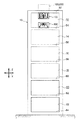
図18に示すように、多層構造の構造物10の最上層(最上階)12に第一実施形態の制震装置100及び第二実施形態の制震装置200が設けられている。
第一実施形態の制震装置100は、最上層(最上階)12の天井を構成するスラブ52に吊下げられるようにして設けられている。
第二実施形態の制震装置200は、最上層(最上階)12の床を構成するスラブ54の上に設けられている。
なお、図18における左右方向(水平方向)をX方向とし、鉛直方向をZ方向とし、X方向とZ方向とに直交する水平方向、すなわち図18に直交する方向をY方向とする。
As shown in FIG. 18, the damping
The
The
Note that the left-right direction (horizontal direction) in FIG. 18 is the X direction, the vertical direction is the Z direction, and the horizontal direction orthogonal to the X direction and the Z direction, that is, the direction orthogonal to FIG.
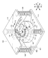
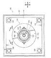
まず、図1〜図4を用いて、第一実施形態の制震装置100について説明する。
First, the damping
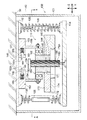
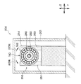
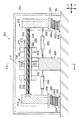
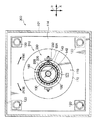
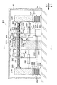
図1〜図3に示すように、制震装置100は、平面視略矩形状の板状の取付部112を有し、この取付部112がスラブ52に、例えば、ボルト等によって固定されている(図2を参照)。平面視における取付部112の四つの隅部にはコイルバネ120の上端が接合されている。コイルバネ120の下端には取付部112と同形状の移動体114の四つの隅部が接合されている。言いかえると、移動体114が、コイルバネ120によって取付部112に吊下げられることによって、移動体114が取付部112(スラブ52)に対して間隔をあけて水平に配置されている。なお、本実施形態においては、コイルバネ120は引張コイルバネで構成されている。
As shown in FIGS. 1 to 3, the
移動体114の中央部部分には、軸体130が鉛直方向を軸方向として、ボルトによって固定されている。なお、本実施形態では軸体130は、ボルトで移動体114に固定されているが、他の方法で固定されていてもよい。
A
移動体114とスラブ52との間には、鉛直方向に移動体114が変位すると、回転慣性を発生させる回転機構部110が設けられている。
回転機構部110は、回転体140、ボールベアリング160、付加質量体170が主要な構成要素とされている。
軸体130は、鉛直方向を軸方向として配置された円柱状の回転体140の孔144に貫通されている。
軸体130の外周面には、雌ネジ132が形成されている。この雌ネジ132は、回転体140の孔144の内周面に形成された雄ネジ142に螺合されている。
Between the moving
The
The
A
一方、取付部112には、水平方向に間隔をあけて一対の固定部150、151が固定されている。固定部150、151は正面視において、取付部112に固定された台部152、153と、該台部152、153から下方に向けて延出され対向配置された一対の板状の板部154、155と、で構成されている。
On the other hand, a pair of fixing
これら一対の固定部150、151の板部154、155の先端部の間には、ボールベアリング160が固定されている。そして、このボールベアリング160を構成する内側のリング162に、前述した回転体140の上部が挿入され固定されている。よって、回転体140は、取付部112(スラブ52)に回転可能に設けられた構成となっている。
A
回転体140の下部の外周には、付加質量体170が接合されている。付加質量体170は、中央に貫通孔171が形成された円盤部172と、円盤部172の下面172Aにおける径方向外側に接合されたリング状の調整錘174と、で構成されている(図3参照)。
An additional
付加質量体170を構成する円盤部172の貫通孔171に回転体140が挿入され、回転体140と接着剤などで接合されている。よって、回転体140と付加質量体170とは一体となって回転する。なお、付加質量体170を構成する調整錘174は、交換可能なように、例えば、ボルトとナットとで円盤部172に取り付けられている。
The
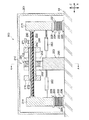
このような構成とされた回転機構部110は、移動体114の鉛直方向の変位に伴い軸体130が鉛直方向に変位し、軸体130の鉛直方向の変位によって取付部112(スラブ52)に回転可能に設けられた回転体140が回転する。そして、回転体140と一体となって付加質量体170が回転し、回転慣性質量が発生する。つまり、移動体114の鉛直方向の変位、すなわち軸体130の鉛直方向の直線運動が付加質量体170の回転運動に変換される。
In the
また、コイルバネ120のバネ定数、移動体114の質量、付加質量体170が回転体140と一体となって回転することによって発生する回転慣性質量等を調整することによって、移動体114の鉛直方向の振動の固有振動数が、スラブ52(構造物10)の鉛直方向の振動の固有振動数と同調するように調整(設定)されている。
Further, by adjusting the spring constant of the
付加質量体170が回転体140と一体となって回転することによって発生する回転慣性質量の調整は、主に調整錘174を調整することによって調整される。しかし、これ以外の方法で調整してもよい。例えば、円盤部172の直径や軸体130の変位量と回転体140の回転速度比などで調整してもよい。
Adjustment of the rotational inertial mass generated when the additional
なお、本実施形態においては、軸体130が鉛直方向上側に変位すると、図2における時計回り方向に回転体140が回転し、軸体130が鉛直方向下側に変位すると、図2における反時計回り方向に回転体が回転するように、雄ネジ142と雌ネジ132とが形成されている。また、本実施形態においては、便宜上、時計回り方向の回転を正回転とし、反時計回り方向を逆回転する。
In the present embodiment, when the
図2に示すように、固定部150、151の台部152、153には、リミッター装置180が設けられている(図1も参照)。リミッター装置180は、一対の固定部150、151の台部152、153から互いに対向する方向に向かって延出する係止部材182、183を備えている。係止部材182、183は圧縮コイルバネ186、187によって対向する方向に押圧されている。係止部材182、183の先端部分の下面には傾斜面184、185が形成されている。また、係止部材182、183の先端182A,183A間の隙間は、軸体130の直径よりも大きく設定されている。
As shown in FIG. 2,
また、軸体130の上端部には、軸体130の軸径よりも大きな円板部134が設けられている。また、円板部134の直径は、係止部材182、183の先端182A,183A間の隙間よりも大きい。
In addition, a
なお、図2、図3に示すように、本実施形態体の制震装置100は、移動体114に何か当るなどして容易に振動しないように、全体がスラブ52に固定された箱形状の筐体101によって囲まれている。
As shown in FIGS. 2 and 3, the
つぎに、本実施形態の作用について説明する。
地震などの外乱によって構造物10(図1参照)が振動すると、移動体114が鉛直方向に振動する。移動体114が鉛直方向に振動すると、移動体114と一体となって軸体130が鉛直方向に振動する。そして、軸体130が鉛直方向に振動すると、回転体140と付加質量体170とが一体となって回転する。
Next, the operation of this embodiment will be described.
When the structure 10 (see FIG. 1) vibrates due to a disturbance such as an earthquake, the moving
前述したように、コイルバネ120のバネ定数、移動体114の質量、付加質量体170が回転することによって発生する回転慣性質量等を調整することによって、移動体114の鉛直方向の振動の固有振動数が、スラブ52(構造物10)の鉛直方向の振動の固有振動数と同調するように調整(設定)されている。よって、外乱によって生じるスラブ52(構造物10)の鉛直方向の振動が低減される。
As described above, the natural frequency of the vertical vibration of the moving
さて、このとき、付加質量体170が回転することで得られる回転慣性質量は、付加質量体170の実際の質量よりも大きな付加質量体を付加したことと等価となり、付加質量体170を回転させない構成と比較し、大きな振動低減効果が得られる。言いかえると、付加質量体170を回転させない構成と比較し、大きな制震効果が得られる。
At this time, the rotational inertial mass obtained by rotating the additional
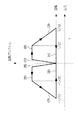
なお、回転慣性質量m’は、図19(A)の式(1)によって求められる。よって、例えば、図19(B)にモデル図の付加質量体を式(1)で計算した計算結果を示す図19(C)の表に示すように、付加質量体mの質量mdが1.2tであった場合には、回転慣性質量m’は、500倍の600tとなる。 The rotational inertia mass m ′ is obtained by the equation (1) in FIG. Therefore, for example, as shown in the table of FIG. 19C, which shows the calculation result of calculating the additional mass body of the model diagram by the equation (1) in FIG. 19B, the mass md of the additional mass m is 1. In the case of 2t, the rotational inertia mass m ′ is 500 times 600t.
よって、例えば、風力等による微振動の制震のみならず地震等の大きな振動であっても大きな制震効果が得られる。 Therefore, for example, a large vibration control effect can be obtained not only with a small vibration control by wind power but also with a large vibration such as an earthquake.
また、製震(振動低減)対象のスラブ52の固有振動数に対する同調は、付加質量体170の回転慣性質量、移動体114の質量、及びコイルバネ120等の諸元を調整することで、自由に且つ幅広く調整するができる。
よって、構造物10全体の固有1次モードのみならず固有2次モードや、更には高次モードの振動や共振が問題となる特定振動数に同調させることによる振動低減効果を得ることもできる。
つまり、本実施形態の制震装置100は、原理的にはチューンドマスダンパーと同様の制震機能を有するが、重い付加質量体を必要することなく、大きな制震効果が得られる。
In addition, tuning to the natural frequency of the
Therefore, not only the natural primary mode of the
That is, the
また、制震装置100は、移動体114の鉛直方向の振動によって、付加質量体170が回転し回転慣性質量が発生するので、スラブ52に吊下げるように設置するだけでよい。よって、一般的なTMDと略同等の設置条件で設置することができる。したがって、例えば、層間変位(スラブ52とスラブ54の水平方向の変位)によって付加質量体が回転する構成と比較し、設置の制限が少ない。
つまり、本実施形態の制震装置100は、層間変位によって付加質量体が回転する構成と比較し設置の制限が少なく、しかも、付加質量体が回転しない一般的なTMDと比較し鉛直方向の振動に対する大きな制震効果が得られる。
Further, since the additional
That is, the
なお、本実施形態においては、付加質量体170の質量は小さいといえども、その負担力は従来のTMDにおける付加質量体による慣性力と同等がそれ以上に大きなものとなる。よって、制震装置100の設計や設置に関しては、充分な強度を見込む必要がある。
そのため、本実施形態では、過大な荷重が作用して破損しないように、移動体114の振動を停止するリミッター装置180を備えている。
In the present embodiment, even if the mass of the additional
Therefore, in this embodiment, a
すなわち、移動体114の鉛直方向の振幅が大きくなると、図4に示すように、軸体130の上端の円板部134が係止部材182、183の傾斜面184、185に当り、係止部材182、183を左右に押し広げ、円板部134が係止部材182、183の上側に移動する。円板部134が係止部材182、183の上側に移動すると、押し広げられた係止部材182、183間が元通り狭くなる。これにより円板部134の係止部材182、183の下側への移動が阻止される。つまり、軸体130の振動、つまり移動体114の振動が停止する。
That is, when the vertical amplitude of the moving
リミッター装置(リミッター手段)は、このような機構の装置に限定されない。例えば、コイルバネ120が許容限度を超える負担力を受けた際には降伏するようにしもてよい。
The limiter device (limiter means) is not limited to a device having such a mechanism. For example, the
なお、図1に二点破線(想像線)で示すように、移動体114に孔822を形成し、取付部112に移動体114の孔822に挿通する棒体820を設けることで、移動体114の水平方向の移動を規制するようにしてもよい。図1では、棒体820及び孔822は一つのみ図示してあるが、複数設けてもよい。
As shown by a two-dot broken line (imaginary line) in FIG. 1, the moving
また、本実施形態では、構造物10の最上層(最上階)12の天井を構成するスラブ52に第一実施形態の制震装置100を設けたがこれに限定されない。最上層12における床を構成するスラブ54に制震装置100を設けてもよい。或いは、スラブ52の上(屋上)に設けてもよい。なお、これらの場合は、制震装置100は、上下逆に設置される。また、コイルバネ120は、引張コイルバネでなく圧縮コイルバネで構成される
Moreover, in this embodiment, although the damping
また、本実施形態の付加質量体170、回転体140、及び保持部材に相当するボールベアリング160及び固定部150、151とは別部材構成となっていたが、これに限定されない。付加質量体170と回転体140とが一体となった構成であってもよい。また、回転体140とボールベアリング160とが一体なった構成であってもよい。
In addition, the additional
また、本実施形態では、軸体130及び回転機構部110は一つであったがこれに限定されない。複数の軸体130及び回転機構部110を備える構成であってもよい。
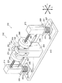
例えば、図5に示す制震装置103のように、一つの移動体115に、X方向に並列に二つの軸体130及び回転機構部110が設けられ、二つの付加質量体170が回転し回転慣性質量が発生する構成であってもよい。
このような構成の場合、スラブ52と移動体115との間隔を広くすることなく、大きな回転慣性質量が得られる。また、この場合、二つの付加質量体170の回転方向が、互いに逆回転するように設定されていてもよい。
In the present embodiment, the number of the
For example, like the
In such a configuration, a large rotational inertial mass can be obtained without increasing the distance between the
なお、図5では、X方向に並んで二つの軸体130及び回転機構部110が設けられていたが、これに限定されない。Y方向に並んで二つの軸体130及び回転機構部110が設けられていてもよい。また、X方向とY方向とに並んで四つの軸体130及び回転機構部110が設けられていてもよい。
In FIG. 5, the two
つぎに、本実施形態の変形例について説明する。なお、本実施形態と同一の部材には、同一の符号を付し、重複する説明は省略する。 Next, a modification of this embodiment will be described. In addition, the same code | symbol is attached | subjected to the member same as this embodiment, and the overlapping description is abbreviate | omitted.
まず、第一変形例の制震装置102について、図6を用いて説明する。
図6に示すように、コイルバネ120の中には、オイルダンパー126が設けられている。オイルダンパー126は、上端が取付部112に接合され、下端が移動体114に接合されている。
First, the
As shown in FIG. 6, an
つぎに、第一変形例の作用について説明する。
本変形例も第一実施形態と同様の作用は奏す。
更に、オイルダンパー126によって、地震時などの外乱による移動体114の振動が減衰し、早期に収束される。
Next, the operation of the first modification will be described.
This modification also has the same effect as the first embodiment.
Further, the
なお、オイルダンパー126は、コイルバネ120の中に設けていなくてもよい。取付部112と移動体114とに接合されていれば、どこに設けられていてもよい。また、オイルダンパー以外の粘性ダンパーであってもよいし、摩擦ダンパーなど、他の減衰部材であってもよい。
Note that the
つぎに、第二変形例の制震装置104について、図7を用いて説明する。
図7に示すように、移動体114は、コイルバネ120(図2参照)でなく、積層ゴム体190で取付部112に接続されている。なお、本実施形態においても、平面視における取付部112の四つの隅部と移動体114とが積層ゴム体190で接続されている。
Next, a
As shown in FIG. 7, the moving
積層ゴム体190は、金属板192とゴム層194とを交互に積層し、全体として、円柱状に形成されている。積層ゴム体190は積層方向(本実施形態では水平方向)に堅く(高剛性)、積層方向と直交する方向(本実施形態では鉛直方向)に柔らかい性能(低剛性)を発揮する。積層ゴム体190の積層方向両端部には積層ゴム体190よりも径方向外側に張り出すフランジ板196、198が一体的に取り付けられている。
The
積層ゴム体190は、積層方向を水平方向(本実施形態ではX方向)として配置され、一方のフランジ板196の上端部196Aが取付部112に接合され、他方のフランジ板198の下端部198Aが移動体114に接合されている。
The
なお、積層ゴム体190の鉛直方向(積層方向と直交する方向)の弾性係数を調整することで、移動体114の鉛直方向の振動の固有振動数を調整することができる。積層ゴム体190の鉛直方向(積層方向と直交する方向)の弾性係数は、ゴム層194を構成するゴムの弾性係数や厚み、或いは積層数などによって調整することができる。
In addition, the natural frequency of the vibration of the
つぎに、第二変形例の作用について説明する。
本変形例も第一実施形態と同様の作用は奏す。
更に、積層ゴム体190は、積層方向の剛性が高いので、地震時などの外乱が加わった際に移動体114にかかる水平方向(本実施形態ではX方向)の荷重が抑制される。
Next, the operation of the second modification will be described.
This modification also has the same effect as the first embodiment.
Furthermore, since the
なお、本変形例においても、オイルダンパー126(図6参照)等の減衰部材を設けてもよい。 Also in this modification, an attenuation member such as an oil damper 126 (see FIG. 6) may be provided.
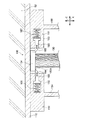
つぎに、図8〜図11を用いて、本発明の第二実施形態に係る制震装置について説明する。 Next, the vibration control device according to the second embodiment of the present invention will be described with reference to FIGS.
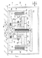
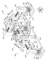
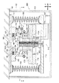
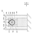
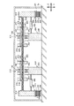
図8に示すように、第二実施形態の制震装置200は、多層構造の構造物の最上階の床を構成するスラブ54の上に設置されている。
スラブ54の上には取付部212が固定され、取付部212の上に水平方向(本実施形態ではX方向)に間隔をあけて、第一積層ゴム体220と第二積層ゴム体221とが固定されている。
As shown in FIG. 8, the
A mounting
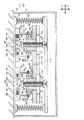
第一積層ゴム体220及び第二積層ゴム体221は、金属板222とゴム層224とを交互に積層し、全体として、円柱状に形成されている。第一積層ゴム体220及び第二積層ゴム体221は積層方向(本実施形態では鉛直方向)に堅く(高剛性)、積層方向と直交する方向(本実施形態では水平方向)に柔らかい性能(低剛性)を発揮する。第一積層ゴム体220及び第二積層ゴム体221の積層方向両端部には径方向外側に張り出すフランジ板226、227、228、229が一体的に取り付けられている。
The first
第一積層ゴム体220及び第二積層ゴム体221は鉛直方向を積層方向として配置され、下側のフランジ板226、227が取付部212(スラブ54)に接合されている。
第一積層ゴム体220の上側のフランジ板228には、柱状の第一移動柱214が固定されている。同様に、第二積層ゴム体221の上側のフランジ板229には、柱状の第二移動柱215が固定されている。よって、第一移動柱214と第二移動柱215とが水平方向(本実施形態ではX方向)に間隔をあけて配置された構成となっている。
そして、第一移動柱214と第二移動柱215の上端部に、水平方向(本実施形態ではX方向)を軸方向として配置された軸体230が接合されている。
The first
A columnar first moving
And the
第一移動柱214と第二移動柱215と間には、第一移動柱214、第二移動柱215、及び軸体230が一体となって水平方向に変位すると、回転慣性を発生させる回転機構部210が設けられている。
回転機構部210は、回転体240、ボールベアリング160、付加質量体270、271が主要な構成要素とされている。
軸体230は、鉛直方向を軸方向として配置された円柱状の回転体240の孔244に貫通している。
軸体230の外周面には、雄ネジ232が形成されている。この雌ネジ232は、回転体240の孔240の内周面に形成された雌ネジ242に螺合されている。
Between the first moving
The
The
A
一方、取付部212における第一移動柱214と第二移動柱215の中間部分には、固定部250が固定されている。固定部250は、取付部212に固定された台部256と、該台部256の上面の隅部から上側に向けて延出された四つの柱部251、252、253、254と、で構成されている。この固定部250の柱部251と柱部253、及び柱部253と柱部254との間に、ボールベアリング160が固定されている。
そして、このボールベアリング160を構成する内側のリング162に、前述した回転体240が挿入され接合されている。つまり、軸体230及び回転体240の軸方向中央部分が回転自在に固定されている。よって、回転体240は、取付部212(スラブ54)に回転可能に設けられた構成となっている。
On the other hand, a fixed
The
回転体240の軸方向両端部の外周には、付加質量体270、271が接合されている。付加質量体270、271は、中央に貫通孔272、273が形成された円盤状とされている。そして、付加質量体270、271の貫通孔272、273に回転体240の両端部が挿入され、接着剤などで接合されている。よって、回転体240と付加質量体270、271とは一体となって回転する。なお、本実施形態においては、付加質量体270と付加質量体271とは同形状且つ同質量とされている。
Additional
このような構成とされた回転機構部210は、第一移動柱214、第二移動柱215、及び軸体230が一体となって水平方向(本実施形態ではX方向)に変位することによって、取付部212(スラブ54)に回転可能に設けられた回転体240が回転する。
そして、回転体240と一体となって付加質量体270、271が回転し、回転慣性質量が発生する。つまり、第一移動柱214及び第二移動柱215の水平方向の変位、すなわち軸体230の水平方向の直線運動が付加質量体170の回転運動に変換される。
In the
Then, the additional
また、第一積層ゴム体220及び第二積層ゴム体221の弾性係数、第一移動柱214及び第二移動柱215の質量、付加質量体270、271が回転することによって発生する回転慣性質量等を調整することによって、第一移動柱214及び第二移動柱215の水平方向(本実施形態ではX方向)の固有振動数が、スラブ54(構造物10)の水平方向(本実施形態ではX方向)の固有振動数と同調するように調整(設定)されている。
In addition, the elastic modulus of the first
付加質量体270、271が回転体140と一体となって回転することによって発生する回転慣性質量の調整は、付加質量体270、271の質量を調整することによって、調整される。なお、第一実施形態と同様に、調整錘174(図1、図2など参照)を接合し、調整錘174の質量を調整することによって調整してもよい。また、これ以外の方法で調整してもよい。例えば、付加質量体270、271の直径や軸体230の変位量と回転体240の回転速度比などで調整してもよい。
Adjustment of the rotational inertial mass generated when the additional
また、第一移動柱214の下端部と固定部250の台部256とに、オイルダンパー262が接合されている。同様に第二移動柱215の下端部と固定部250の台部256とに、オイルダンパー263が接合されている。
An
なお、本実施形態においては、軸体230が図9における水平方向(X方向)右側に変位すると(図11参照)、図10における時計回り方向に回転体240が回転し、軸体230が図9における水平方向(X方向)左側下側に変位すると、図2における反時計回り方向に回転体240が回転するように、雄ネジ242と雌ネジ232とが形成されている。また、本実施形態においては、便宜上、時計回り方向の回転を正回転とし、反時計回り方向を逆回転する。
In the present embodiment, when the
また、制震装置200は、移動柱214、215に何か当るなどして容易に振動しないように全体がスラブ54に固定された箱形状の筐体201で囲まれている。
また、第一実施形態と同様に、過大な荷重が作用して破損しないように、移動体114の振動を停止するリミッター装置やリミッター機構を備えていてもよい。
Further, the
Further, similarly to the first embodiment, a limiter device or a limiter mechanism for stopping the vibration of the moving
つぎに、本実施形態の作用について説明する。
地震などの外乱によって構造物10(図18参照)が振動すると、第一移動柱214及び第二移動柱215と軸体230とが一体となって水平方向(本実施形態ではX方向)に振動する(図9と図11を参照)。そして、軸体230が水平方向に振動すると、回転体240と付加質量体270、271とが一体となって回転する。そして、移動柱214、215の水平方向の振動の固有振動数が、スラブ54の水平方向(本実施形態ではX方向)の固有振動数と同調(又は略同調)するように調整(設定)されることで、スラブ54(構造物10)の水平方向の振動が低減される。
Next, the operation of this embodiment will be described.
When the structure 10 (see FIG. 18) vibrates due to a disturbance such as an earthquake, the first moving
付加質量体270、271が回転することで得られる回転慣性質量は、付加質量体270、271の実際の質量よりも大きな付加質量体を付加したことと等価となり、付加質量体270、271を回転させない構成と比較し、大きな振動低減効果が得られる。言いかえると、付加質量体270、271を回転させない構成と比較し、大きな制震効果が得られる。
The rotational inertial mass obtained by rotating the additional
また、制震装置200は、第一移動柱214及び第二移動柱215の水平方向の振動によって、付加質量体270、270が回転し回転慣性質量が発生するので、スラブ54の上に設置するだけでよい。よって、一般的なTMDと略同等の設置条件で設置することができる。したがって、例えば、層間変位(スラブ52とスラブ54の水平方向の変位)によって付加質量体が回転する構成と比較し、設置の制限が少ない。
つまり、本実施形態の制震装置200は、層間変位によって付加質量体が回転する構成と比較し設置の制限が少なく、しかも、付加質量体を回転させない一般的なTMDと比較し鉛直方向の振動に対する大きな制震効果が得られる。
Further, since the additional
That is, the
また、本実施形態においては、第一移動柱214と第二移動柱215との間に設けられた固定部250に固定されたボールベアリング160によって、軸体230及び回転体240の軸方向中央部分が回転自在に固定されている。そして、第一移動柱214と第二移動柱215との間に設けられた固定部250に固定されたボールベアリング160の軸方向両外側にそれぞれ付加質量体270、271が設けられている。
したがって、より大きな回転慣性質量が得られる。また、軸体230の軸方向中央部分が支持されているので、軸体230の軸方向の全長を長くしても、軸体230の湾曲が抑制される。
Further, in the present embodiment, the axially central portions of the
Therefore, a larger rotational inertial mass is obtained. Moreover, since the axial direction center part of the
また、オイルダンパー262、263によって、移動柱214、215の振動が減衰し、早期に収束される。
なお、オイルダンパー262、263は、必須の部材でない。適宜省略してもよい。また、オイルダンパー以外の粘性ダンパーであってもよいし、摩擦ダンパーなど、他の減衰部材であってもよい。
In addition, the vibrations of the moving
The
また、本実施形態の付加質量体270、271、回転体240、及び保持部材に相当するボールベアリング160及び固定部250とは別部材構成となっていたが、これに限定されない。付加質量体270、271と回転体240とが一体となった構成であってもよい。また、回転体240とボールベアリング160とが一体なった構成であってもよい。
In addition, the additional
また、本実施形態では、回転機構部210は、一つであったがこれに限定されない。複数の回転機構部210を備える構成であってもよい。
例えば、図12に示す制震装置202のように、複数の回転機構部210が並列に設けられ、合計で四つの付加質量体270、271が回転し回転慣性質量が発生する構成であってもよい。このような構成の場合、移動柱216と対向する移動柱(図示略)との間隔を広くすることなく、大きな回転慣性質量が得られる。また、この場合、二つの回転機構部210の回転方向が、互いに逆回転するように設定されていてもよい。
In the present embodiment, the number of
For example, as in the
また、図9の固定部250を含む左側(又は右側)のみで構成されていてもよい。つまり、第一支柱部214、固定部250、ボールベアリング160、積層ゴム本体220、オイルダンパー262、軸体230(正確には軸体230よりも短い軸体)で構成されていてもよい。
Moreover, you may be comprised only by the left side (or right side) containing the fixing |
また、図21に示すように、第一移動柱214と第二移動柱215との間に複数の固定部250及びボールベアリング160を設け、ボールベアリング160の軸方向両外側にそれぞれ付加質量体270、271が設けられている構成としてもよい。
Further, as shown in FIG. 21, a plurality of fixed
なお、本実施形態では、構造物10の最上層(最上階)12の天井を構成するスラブ54に第二実施形態の制震装置200を設けたがこれに限定されない。最上層12における床を構成するスラブ52に吊下げるようにして制震装置200を設けてもよい。或いは、スラブ52の上(屋上)に設けてもよい。
In the present embodiment, the
また、本実施形態ではX方向の振動に対して振動低減効果を有するように制震装置200が配置されている。しかし、構造物10の構造、構造物10が構築された地盤、地震の揺れの方向などを考慮し、適宜、配置方向を決定すればよい。
In the present embodiment, the
更に、複数の振動方向に対して、振動低減効果(制震効果)を有するように、制震装置200を異なる方向に複数設けてもよい。例えば、図12に示すように、X方向に沿って配置された制震装置200とY方向に沿って配置された制震装置200とを設けることで、X方向とY方向との両方向の水平方向の振動が低減される。
Furthermore, a plurality of
なお、図18に示すように、構造物10は、第一実施形態の制震装置100と第二実施形態の制震装置200との両方が設けられている。よって、構造物10は、鉛直方向と水平方向の両方の振動が低減される。
As shown in FIG. 18, the
また、構造物10では、図18に示すように、最上層(最上階)12(又は屋上)に第一実施形態の制震装置100と第二実施形態の制震装置200を設けたがこれに限定されない。最上層12以外の他の層に設けてもよい。或いは、一つの層に限らず複数の層に設ければよい。また、第一実施形態の制震装置100と第二実施形態の制震装置200とを別々の層に設けてもよい。
Moreover, in the
つまり、本実施形態の構造物10における層12、層14、層16、層18、層20、層22の、少なくともいずれか一つの層に、第一実施形態の制震装置100及び第二実施形態の制震装置200を少なくとも一方を設ければよい。
That is, at least one of the
つぎに第三実施形態の制震装置300について、図14と図15を用いて説明する。なお、上記実施形態と同一の部材には同一の符号を付し、重複する説明は省略する。
Next, a
図14と図15とに示すように、第三実施形態の制震装置300は、第一実施形態の制震装置100とは、回転アシスト装置310が備えられている点が異なり、他の構成は、同じである。よって、回転アシスト装置310のみを詳しく説明する。
As shown in FIGS. 14 and 15, the
回転アシスト装置310は、圧力センサー320、駆動装置330、回転速度検知センサー340、制御装置350が主要な構成要素とされている。
The
圧力センサー320は、軸体130と移動体114との間に挟まれている。また、圧力センサー320は、軸体130と移動体114との間に鉛直方向に作用する圧力を検知する(軸体130に作用する軸方向の圧力を検知する)。
The
回転速度検知センサー340は、回転体140の下面に設けられ、回転体140の回転速度を検知する。
The rotation
回転体140を回転駆動するための駆動装置330は、ボールベアリング160の上側に設けられている。駆動装置330は、回転体140が挿入されたボールベアリング160の内側のリング162の上に設けられリング162と一体となって回転するスプロケット336と、駆動モータ334の駆動軸332とに、チェーン338が巻きかけられた構成とされている。
A driving
よって、駆動モータ334の駆動軸332が回転すると、回転体140が回転する。なお、駆動モータ334の駆動軸332は正回転と逆回転の両方向に回転する。つまり、駆動装置330は、回転体140を正回転と逆回転との両方に回転させることができる。
Therefore, when the
圧力センサー320、駆動装置330、及び回転速度検知センサー340は、制御装置350に接続されている。また、駆動装置330(駆動モータ334)は制御装置によって制御されている。
The
なお、本実施形態に係る制御装置350の電気系の構造は、どのようなものであってもよい。例えば、制御装置350は、全体の動作を司るCPU(中央処理装置)、CPUによる各種処理プログラムの実行時のワークエリア等として用いられるRAM、各種制御プログラムや各種パラメータ等が予め記憶されたROM、各種情報を記憶するために用いられるハードディスク装置等の二次記憶装置等、更には、圧力センサー320、駆動装置330(駆動モータ334)、及び回転速度検知センサー340の駆動電源が備えられている。
The electrical system structure of the
つぎに、本実施形態の作用について説明する。
ここで、第一実施形態の制震装置100において、回転体140が回転を開始するためには、種々の抵抗力(各部材間の摩擦抵抗力等)によって、閾値以上の力が必要とされる。このため、外乱によって移動体114(軸体130)が鉛直方向に変位しようとしても、閾値を越える力が発生するまで、回転体140(付加質量体170)は回転を開始しない。
Next, the operation of this embodiment will be described.
Here, in the
しかし、本実施形態は、回転体140(付加質量体170)が回転を開始する際(正確に回転を開始する前)に、駆動装置330によって回転体140に回転力を付与することによって、外乱が発生してから回転体140が回転を開始するまでの時間を短くしている。
However, in the present embodiment, when the rotating body 140 (additional mass body 170) starts rotating (before the rotation accurately starts), the driving
或いは、閾値を越えない程度の(回転体140(付加質量体170)が回転しない程度の)外乱であっても、回転体140が回転を開始することで、微細な振動であっても制震効果が得られるようにしている。
Alternatively, even if the disturbance does not exceed the threshold (the rotating body 140 (additional mass body 170) does not rotate), the
なお、本実施形態では、このように回転体140に付与する回転力の制御を回転アシスト制御と記すことにする。
In the present embodiment, the control of the rotational force applied to the
つぎに、制御装置350による回転アシスト制御について、詳しく説明する。
まず、外乱によって移動体114が上側に変位しようとする。しかし、種々の抵抗力によって、回転体140は回転しない。よって、移動体114と軸体130との間の圧力が、外乱が作用しない場合よりも大きくなる。また、回転体140が回転していないので、回転速度は検知されない。
Next, the rotation assist control by the
First, the moving
このような状態となると、制御装置350は、駆動装置330を制御し、回転体140を正回転させる方向に回転力を付与する。これにより回転体140は回転を開始する。回転体140が回転すると回転体140の回転速度が検知される。
In such a state, the
回転体140の回転速度に応じて回転アシスト力を低下させていく。或いは、所定の回転速度に達すると、クラッチ機構等で回転力の付与を中断する。
The rotation assist force is reduced according to the rotation speed of the
振動の振幅が反転し移動体114が下側に変位しようとする。しかし、種々の抵抗力によって、回転体140は回転しない。よって、移動体114と軸体130との間の圧力が、外乱が作用しない場合よりも小さくなる。また、回転体140は回転していないので、回転速度は検知されない。
The amplitude of vibration is reversed, and the moving
このような状態となると、制御装置350は駆動装置330を制御し、回転体140を逆回転させる方向に回転力を付与する。これにより回転体140は回転を開始する。回転体140が回転すると回転体140の回転速度が検知される。
In such a state, the
回転体140の回転速度に応じて回転アシスト力を低下させていく。或いは、所定の回転速度に達すると、クラッチ機構等で回転力の付与を中断する。
The rotation assist force is reduced according to the rotation speed of the
振動の振幅が反転し移動体114が上側に変位しようとすると、同様に回転体140に正回転方向の回転力を付与する。
When the amplitude of the vibration is reversed and the moving
このように、回転体140(付加質量体170)が回転を開始する際に、駆動装置330によって回転体140に回転力を付与することによって、外乱が発生してから回転体140が回転を開始するまでの時間が短くなる。
As described above, when the rotating body 140 (additional mass body 170) starts to rotate, the
或いは、閾値を越えない程度の(回転体140(付加質量体170)が回転しない程度の)外乱であっても、回転体140が回転を開始することで、微細な振動であっても制震効果が得られる。
Alternatively, even if the disturbance does not exceed the threshold (the rotating body 140 (additional mass body 170) does not rotate), the
なお、上記回転アシスト制御を模式的に示したのが図20のグラフである。なお、このグラフは、実際に圧力センサー340及び回転速度検知センサー340が検知した数値の変化を正確に示したものではなく、あくまでも制御を説明するために模式的に図示したグラフである。
FIG. 20 is a graph schematically showing the rotation assist control. In addition, this graph does not show the change of the numerical value actually detected by the
なお、回転アシスト制御は、上記制御に限定されない。
例えば、回転速度検知センサー340がなくてもよい。この場合、例えば、回転体140が回転力を付与してから所定時間経過後、自動的にクラッチ機構等で回転力の付与を中断すればよい。
The rotation assist control is not limited to the above control.
For example, the rotation
また、例えば、微小振動では回転体14が回転しないように、移動体114と軸体130との間に作用する圧力値が、外乱が生じていない状態よりも大きく且つ所定値よりも大きくなると、正方向に回転体140を回転させる回転力を回転体140に付与し、外乱が生じていない状態よりも小さく且つ所定値をよりも小さくなると逆方向に(例えば反時計回りに)回転体140を回転させる回転力を回転体140に付与するように制御してもよい。
Further, for example, when the pressure value acting between the moving
また、例えば、移動体114の鉛直方向の変位速度を検知する移動体変位速度検知手段を設け、より正確に回転体140に付与する回転力を最適化してもよい。
Further, for example, a moving body displacement speed detecting means for detecting the displacement speed in the vertical direction of the moving
また、過大な荷重がかかり破損しないように、回転体140の回転速度が所定値以上となった場合は、駆動装置330を利用してブレーキをかけるようにしてもよい。
Further, in order to prevent an excessive load from being damaged, the brake may be applied using the
また、第三実施形態の回転アシスト装置及び制御は、第一実施形態の変形例にも適用することができる。 Moreover, the rotation assistance apparatus and control of 3rd embodiment are applicable also to the modification of 1st embodiment.
つぎに第四実施形態の制震装置400について、図14と図15を用いて説明する。なお、上記実施形態と同一の部材には同一の符号を付し、重複する説明は省略する。
Next, a
図16と図17とに示すように、第四実施形態の制震装置400は、第二実施形態の制震装置200とは、回転アシスト装置410が備えられている点が異なり、他の構成は、同じである。よって、回転アシスト装置410のみを詳しく説明する。更に、回転アシスト装置410は、第三実施形態の回転アシスト装置310と略同様の構成あるので、重複する説明は省略する。
As shown in FIGS. 16 and 17, the
回転アシスト装置410は、圧力センサー320、駆動装置430、回転速度検知センサー340、制御装置350が主要な構成要素とされている。
The
圧力センサー320は、軸体230と第一移動柱214及び第二移動柱215との間に挟まれている。また、圧力センサー320は、軸体230と第一移動柱214及び第二移動柱215との間に水平方向(本実施形態はX方向)に作用する圧力を検知する(軸体230に作用する軸方向の圧力を検知する)。
The
回転速度検知センサー340は、回転体240の軸方向両端部に設けられ、回転体240の回転速度を検知する。
The rotation
回転体240を回転駆動するための駆動装置430は、ボールベアリング160のX方向右側に設けられている。駆動装置430は、回転体240が挿入されたボールベアリング160の内側のリング162の横に設けられリング162と一体となって回転するスプロケット336と、駆動モータ334の駆動軸332とに、チェーン338が巻きかけられた構成とされている。
A driving
よって、駆動モータ334の駆動軸332が回転すると、回転体240が回転する。なお、駆動モータ334の駆動軸332は正回転と逆回転の両方向に回転する。つまり、駆動装置330は、回転体240を正回転と逆回転との両方に回転させることができる。
Therefore, when the
圧力センサー320、駆動装置430、及び回転速度検知センサー340は、制御装置350に接続されている。また、駆動装置430(駆動モータ334)は制御装置によって制御されている。
The
つぎに、本実施形態の作用について説明する。
ここで、第二実施形態の制震装置200において、回転体240が回転を開始するためには、種々の抵抗力(各部材間の摩擦抵抗力等)によって、閾値以上の力が必要とされる。このため、外乱によって第一移動柱214及び第二移動柱215(軸体230)が鉛直方向に変位しようとしても、閾値を越える力が発生するまで、回転体140(付加質量体170)は回転を開始しない。
Next, the operation of this embodiment will be described.
Here, in the
しかし、本実施形態は、回転体240(付加質量体270、271)が回転を開始する際に、駆動装置330によって回転体240に回転力を付与することによって、外乱が発生してから回転体240が回転を開始するまでの時間を短くしている。
However, in the present embodiment, when the rotating body 240 (additional
或いは、閾値を越えない程度の(回転体240(付加質量体270、271)が回転しない程度の)外乱であっても、回転体240が回転を開始することで、微細な振動であっても制震効果が得られるようにしている。
Alternatively, even if there is a disturbance that does not exceed the threshold (so that the rotating body 240 (additional
なお、本実施形態の回転アシスト制御は、第三実施形態と上下方向が左右方向となる他は、同一の制御であるので、説明を省略する。 Note that the rotation assist control of this embodiment is the same as that of the third embodiment except that the vertical direction is the left-right direction, and a description thereof will be omitted.
尚、本発明は上記実施形態に限定されない。本発明の要旨を逸脱しない範囲において種々なる態様で実施し得ることは言うまでもない。 The present invention is not limited to the above embodiment. Needless to say, various embodiments can be implemented without departing from the scope of the present invention.
例えば、弾性部材の例として、コイルバネ120、積層ゴム体190、第一積層ゴム体220、第二積層ゴム体221を用いたがこれらに限定されない。鉛直方向又は水平方向に弾性変形可能な部材であればよい。
For example, as an example of the elastic member, the
10 構造物(制震構造物)
52 スラブ(構造床)
54 スラブ(構造床)
56 スラブ(構造床)
58 スラブ(構造床)
60 スラブ(構造床)
62 スラブ(構造床)
64 スラブ(構造床)
100 制震装置
102 制震装置
103 制震装置
104 制震装置
110 回転機構部
114 移動体
115 移動体
120 コイルバネ(弾性部材)
126 オイルダンパー(減衰部材)
130 軸体
132 雌ネジ(螺合手段)
140 回転体
142 雄ネジ(螺合手段)
160 ボールベアリング(保持体)
170 付加質量体
190 積層ゴム体(弾性部材)
200 制震装置
202 制震装置
210 回転機構部
214 第一移動柱(第一移動部、移動体)
215 第二移動柱(第二移動部、移動体)
220 第一積層ゴム体(第一弾性部材、弾性部材)
221 第二積層ゴム体(第一弾性部材、弾性部材)
230 軸体
232 雌ネジ(螺合手段)
240 回転体
242 雄ネジ(螺合手段)
262 オイルダンパー(減衰部材)
263 オイルダンパー(減衰部材)
270 付加質量体
271 付加質量体
300 制震装置
310 回転アシスト装置(回転力付与手段)
320 圧力センサー(圧力検知手段)
330 駆動装置(駆動手段)
340 回転速度検知センサー(回転速度検知手段)
400 制震装置
410 回転アシスト装置(回転力付与手段)
430 駆動装置(駆動手段)
10 Structure (damping structure)
52 Slab (structure floor)
54 Slab (structure floor)
56 Slab (structure floor)
58 Slab (structure floor)
60 Slab (structure floor)
62 Slab (structure floor)
64 Slab (structure floor)
DESCRIPTION OF
126 Oil damper (damping member)
130
140
160 Ball bearing (holding body)
170
200 Damping
215 Second moving column (second moving part, moving body)
220 First laminated rubber body (first elastic member, elastic member)
221 Second laminated rubber body (first elastic member, elastic member)
230
240
262 Oil damper (damping member)
263 Oil damper (damping member)
270 Additional
320 Pressure sensor (pressure detection means)
330 Driving device (driving means)
340 Rotational speed detection sensor (Rotational speed detection means)
400
430 Driving device (driving means)
Claims (13)
前記構造床に設けられ、前記移動体の鉛直方向の変位を付加質量体の回転運動に変換する回転機構部と、
を備え、
前記移動体の鉛直方向の振動の固有振動が、前記構造床の鉛直方向の振動の固有振動に同調するように設定されている制震装置。 An elastic member connected to the moving body and the structural floor, supporting the moving body, and elastically deforming in a vertical direction;
A rotation mechanism that is provided on the structural floor and converts the displacement of the movable body in the vertical direction into the rotational motion of the additional mass body;
With
A vibration control device that is set so that a natural vibration of a vertical vibration of the moving body is synchronized with a natural vibration of a vertical vibration of the structural floor.
前記回転機構部は、
前記軸体が挿入される回転体と、
前記構造床に設けられ、前記回転体を回転可能に保持する保持体と、
前記軸体の外周面と前記回転体の内周面とに設けられ、前記軸体の軸方向の直線運動を前記回転体の軸周りの回転運動に変換する螺合手段と、
前記回転体と一体となって軸周りに回転する前記付加質量体と、
を有する、
請求項1又は請求項2に記載の制震装置。 The moving body has a shaft body arranged with the vertical direction as an axial direction,
The rotation mechanism unit is
A rotating body into which the shaft is inserted;
A holding body provided on the structure floor and rotatably holding the rotating body;
A screwing means provided on an outer peripheral surface of the shaft body and an inner peripheral surface of the rotating body, and converting a linear motion in the axial direction of the shaft body into a rotational motion around the axis of the rotating body;
The additional mass body that rotates integrally with the rotating body around an axis;
Having
The vibration control apparatus according to claim 1 or 2.
前記回転機構部が、前記軸体毎に複数備えられている、
請求項3に記載の制震装置。 The movable body has a plurality of the shaft bodies arranged in parallel,
A plurality of the rotation mechanism units are provided for each shaft body,
The vibration control device according to claim 3.
前記構造床に設けられ、前記移動体の水平方向の変位を付加質量体の回転運動に変換する回転機構部と、
を備え、
前記移動体の水平方向の振動の固有振動が、前記構造床の水平方向の振動の固有振動に同調するように設定されている制震装置。 An elastic member connected to the moving body and the structural floor, supporting the moving body, and elastically deforming in a horizontal direction;
A rotation mechanism that is provided on the structural floor and converts the displacement in the horizontal direction of the movable body into the rotational motion of the additional mass; and
With
A vibration control device that is set so that a natural vibration of a horizontal vibration of the movable body is synchronized with a natural vibration of a horizontal vibration of the structural floor.
請求項5に記載の制震装置。 Having a damping member for damping the vibration of the moving body,
The vibration control device according to claim 5.
前記回転機構部は、
前記軸体が挿入される回転体と、
前記構造床に設けられ、前記回転体を回転可能に保持する保持体と、
前記軸体の外周面と前記回転体の内周面とに設けられ、前記軸体の軸方向の直線運動を前記回転体の軸周りの回転運動に変換する螺合手段と、
前記回転体と一体となって軸周りに回転する前記付加質量体と、
を有する、
請求項5又は請求項6に記載の制震装置。 The moving body has a shaft body arranged with the horizontal direction as an axial direction,
The rotation mechanism unit is
A rotating body into which the shaft is inserted;
A holding body provided on the structure floor and rotatably holding the rotating body;
A screwing means provided on an outer peripheral surface of the shaft body and an inner peripheral surface of the rotating body, and converting a linear motion in the axial direction of the shaft body into a rotational motion around the axis of the rotating body;
The additional mass body that rotates integrally with the rotating body around an axis;
Having
The vibration control device according to claim 5 or 6.
前記構造床に水平方向に間隔をあけて設けられた一対の第一移動部及び第二移動部と、
前記第一移動部と前記第二移動部とに接合された前記軸体と、
を有し、
前記弾性部材は、
前記第一移動部と前記構造床との間に設けられた第一弾性部材と、
前記第二移動部と前記構造床との間に設けられた第二弾性部材と、
を有し、
前記第一移動部と前記第二移動部との間に一つ又は複数の前記保持部が設けられ、
前記保持部の軸方向両外側にそれぞれ前記付加質量体が設けられている、
請求項7に記載の制震装置。 The moving body is
A pair of first moving part and second moving part provided at an interval in the horizontal direction on the structural floor;
The shaft body joined to the first moving part and the second moving part;
Have
The elastic member is
A first elastic member provided between the first moving part and the structural floor;
A second elastic member provided between the second moving part and the structural floor;
Have
One or more holding parts are provided between the first moving part and the second moving part,
The additional mass bodies are respectively provided on both outer sides in the axial direction of the holding portion,
The vibration control device according to claim 7.
前記回転機構部が、前記軸体毎に複数備えられている、
請求項7又は請求項8に記載の制震装置。 The movable body has a plurality of the shaft bodies arranged in parallel,
A plurality of the rotation mechanism units are provided for each shaft body,
The vibration control device according to claim 7 or claim 8.
請求項1〜請求項9のいずれか1項に記載の制震装置。 When the additional mass body starts to rotate, the additional mass body has a rotational force applying means for applying a rotational force in a rotating direction.
The vibration control device according to any one of claims 1 to 9.
前記回転力付与手段は、
前記回転体を回転駆動させる駆動手段と、
前記軸体に作用する軸方向の圧力を検知する圧力検知手段と、
前記圧力検知手段で検知された圧力値に基づいて、前記回転体を回転駆動させる回転方向を決定し、前記駆動手段を制御して決定された回転方向に前記回転体を回転駆動させる制御手段と、
を有する、
請求項3、請求項4、請求項7、請求項8、請求項9のいずれか1項に記載の制震装置。 When the additional mass body starts to rotate, it has a rotational force applying means for applying a rotational force in a direction in which the additional mass body rotates,
The rotational force applying means is
Driving means for rotating the rotating body;
Pressure detecting means for detecting axial pressure acting on the shaft body;
Control means for determining a rotational direction for rotationally driving the rotating body based on the pressure value detected by the pressure detecting means, and for controlling the driving means to rotationally drive the rotational body in the determined rotational direction; ,
Having
The vibration control device according to any one of claim 3, claim 4, claim 7, claim 8, and claim 9.
前記回転体の回転速度を検知する回転速度検知手段を有し、
前記制御手段は、
前記圧力検知手段で検知された圧力値と、前記回転速度検知手段で検知された回転速度値と、に基づいて前記駆動手段が前記回転体に付与する回転力を算出すると共に、算出結果に基づいて前記駆動手段の回転力を制御する、
請求項11に記載の制震装置。 The rotational force applying means is
A rotation speed detecting means for detecting the rotation speed of the rotating body;
The control means includes
Based on the pressure value detected by the pressure detecting means and the rotational speed value detected by the rotational speed detecting means, the rotational force applied by the driving means to the rotating body is calculated, and based on the calculation result. To control the rotational force of the drive means,
The vibration control device according to claim 11.
Priority Applications (1)
| Application Number | Priority Date | Filing Date | Title |
|---|---|---|---|
| JP2009220789A JP2011069104A (en) | 2009-09-25 | 2009-09-25 | Seismic control device and seismic control structure |
Applications Claiming Priority (1)
| Application Number | Priority Date | Filing Date | Title |
|---|---|---|---|
| JP2009220789A JP2011069104A (en) | 2009-09-25 | 2009-09-25 | Seismic control device and seismic control structure |
Publications (1)
| Publication Number | Publication Date |
|---|---|
| JP2011069104A true JP2011069104A (en) | 2011-04-07 |
Family
ID=44014618
Family Applications (1)
| Application Number | Title | Priority Date | Filing Date |
|---|---|---|---|
| JP2009220789A Pending JP2011069104A (en) | 2009-09-25 | 2009-09-25 | Seismic control device and seismic control structure |
Country Status (1)
| Country | Link |
|---|---|
| JP (1) | JP2011069104A (en) |
Cited By (18)
| Publication number | Priority date | Publication date | Assignee | Title |
|---|---|---|---|---|
| CN103016605A (en) * | 2012-12-17 | 2013-04-03 | 南京航空航天大学 | Liquid resistance type dynamic vibration absorber with adjustable parameters |
| JP2013177982A (en) * | 2013-06-20 | 2013-09-09 | Nagasaki Univ | Vibration control device and control method therefor |
| CN103696909A (en) * | 2013-12-24 | 2014-04-02 | 常州容大结构减振设备有限公司 | Wind-resistant TMD system with power generation function |
| CN103774771A (en) * | 2014-01-26 | 2014-05-07 | 智性科技南通有限公司 | Rigidity and dampness integrating horizontal omnidirectional tuned mass damper |
| CN105155711A (en) * | 2015-08-18 | 2015-12-16 | 辽宁工业大学 | Three-dimensional foundation composite damper |
| KR101644920B1 (en) * | 2016-02-19 | 2016-08-04 | (주)신명전력산업 | The distribution Board with Earthquake-proof |
| JP2017044328A (en) * | 2015-08-28 | 2017-03-02 | 株式会社免制震ディバイス | Mass damper |
| CN108071181A (en) * | 2017-12-26 | 2018-05-25 | 洛阳理工学院 | A kind of civil engineering anti-seismic structure and its method |
| CN110805529A (en) * | 2019-09-20 | 2020-02-18 | 株洲时代新材料科技股份有限公司 | Tuned mass damping device |
| CN110805530A (en) * | 2019-09-20 | 2020-02-18 | 株洲时代新材料科技股份有限公司 | Tuned mass damping device |
| WO2020239590A1 (en) * | 2019-05-24 | 2020-12-03 | Soh Wind Tunnels Aps | Pendulum mass damper |
| CN112127496A (en) * | 2020-09-24 | 2020-12-25 | 湖南大学 | Ball screw type eddy current damper with negative-stiffness nonlinear energy trap |
| WO2021051372A1 (en) * | 2019-09-20 | 2021-03-25 | 大连理工大学 | Self-reset tuned mass damper based on eddy current and shape memory alloy technology |
| CN112695911A (en) * | 2020-12-18 | 2021-04-23 | 中铁大桥局集团有限公司 | Self-adaptive variable-rigidity tuned mass damper |
| CN113236007A (en) * | 2021-05-24 | 2021-08-10 | 西京学院 | Rigidity-adjustable particle shock absorber for high-rise civil structure |
| WO2023274620A1 (en) * | 2021-06-28 | 2023-01-05 | Siemens Gamesa Renewable Energy A/S | Dynamic vibration absorber |
| WO2024036963A1 (en) * | 2022-08-15 | 2024-02-22 | 沈阳工业大学 | Active-passive composite control system for preventing swinging of suspended object |
| US12241519B2 (en) | 2019-09-20 | 2025-03-04 | Zhuzhou Times New Material Technology Co., Ltd | Tuned mass damping device |
-
2009
- 2009-09-25 JP JP2009220789A patent/JP2011069104A/en active Pending
Cited By (27)
| Publication number | Priority date | Publication date | Assignee | Title |
|---|---|---|---|---|
| CN103016605A (en) * | 2012-12-17 | 2013-04-03 | 南京航空航天大学 | Liquid resistance type dynamic vibration absorber with adjustable parameters |
| JP2013177982A (en) * | 2013-06-20 | 2013-09-09 | Nagasaki Univ | Vibration control device and control method therefor |
| CN103696909A (en) * | 2013-12-24 | 2014-04-02 | 常州容大结构减振设备有限公司 | Wind-resistant TMD system with power generation function |
| CN103696909B (en) * | 2013-12-24 | 2016-03-30 | 常州容大结构减振股份有限公司 | There is the wind proof TMD system of electricity generate function |
| CN103774771A (en) * | 2014-01-26 | 2014-05-07 | 智性科技南通有限公司 | Rigidity and dampness integrating horizontal omnidirectional tuned mass damper |
| CN105155711A (en) * | 2015-08-18 | 2015-12-16 | 辽宁工业大学 | Three-dimensional foundation composite damper |
| JP2017044328A (en) * | 2015-08-28 | 2017-03-02 | 株式会社免制震ディバイス | Mass damper |
| KR101644920B1 (en) * | 2016-02-19 | 2016-08-04 | (주)신명전력산업 | The distribution Board with Earthquake-proof |
| CN108071181A (en) * | 2017-12-26 | 2018-05-25 | 洛阳理工学院 | A kind of civil engineering anti-seismic structure and its method |
| CN108071181B (en) * | 2017-12-26 | 2019-07-19 | 洛阳理工学院 | A kind of civil engineering seismic structure and its method |
| US12031352B2 (en) | 2019-05-24 | 2024-07-09 | Soh Wind Tunnels Aps | Pendulum mass damper |
| EP3976906B1 (en) * | 2019-05-24 | 2024-02-14 | Soh Wind Tunnels ApS | Pendulum mass damper |
| WO2020239590A1 (en) * | 2019-05-24 | 2020-12-03 | Soh Wind Tunnels Aps | Pendulum mass damper |
| CN110805530B (en) * | 2019-09-20 | 2020-12-01 | 株洲时代新材料科技股份有限公司 | Tuned mass damping device |
| CN110805530A (en) * | 2019-09-20 | 2020-02-18 | 株洲时代新材料科技股份有限公司 | Tuned mass damping device |
| US12241519B2 (en) | 2019-09-20 | 2025-03-04 | Zhuzhou Times New Material Technology Co., Ltd | Tuned mass damping device |
| WO2021051372A1 (en) * | 2019-09-20 | 2021-03-25 | 大连理工大学 | Self-reset tuned mass damper based on eddy current and shape memory alloy technology |
| CN110805529A (en) * | 2019-09-20 | 2020-02-18 | 株洲时代新材料科技股份有限公司 | Tuned mass damping device |
| CN110805529B (en) * | 2019-09-20 | 2020-12-01 | 株洲时代新材料科技股份有限公司 | Tuned mass damping device |
| US11293175B2 (en) | 2019-09-20 | 2022-04-05 | Dalian University Of Technology | Self-resetting tuned mass damper based on eddy current and shape memory alloy technology |
| CN112127496B (en) * | 2020-09-24 | 2022-02-08 | 湖南大学 | Ball screw type eddy current damper with negative-stiffness nonlinear energy trap |
| CN112127496A (en) * | 2020-09-24 | 2020-12-25 | 湖南大学 | Ball screw type eddy current damper with negative-stiffness nonlinear energy trap |
| CN112695911A (en) * | 2020-12-18 | 2021-04-23 | 中铁大桥局集团有限公司 | Self-adaptive variable-rigidity tuned mass damper |
| CN113236007B (en) * | 2021-05-24 | 2022-12-02 | 西京学院 | Rigidity-adjustable particle shock absorber for high-rise civil structure |
| CN113236007A (en) * | 2021-05-24 | 2021-08-10 | 西京学院 | Rigidity-adjustable particle shock absorber for high-rise civil structure |
| WO2023274620A1 (en) * | 2021-06-28 | 2023-01-05 | Siemens Gamesa Renewable Energy A/S | Dynamic vibration absorber |
| WO2024036963A1 (en) * | 2022-08-15 | 2024-02-22 | 沈阳工业大学 | Active-passive composite control system for preventing swinging of suspended object |
Similar Documents
| Publication | Publication Date | Title |
|---|---|---|
| JP2011069104A (en) | Seismic control device and seismic control structure | |
| JP6902191B2 (en) | Damping device and seismic isolation structure | |
| JP5399540B1 (en) | Structure damping device | |
| JP6529884B2 (en) | SPRING MECHANISM AND VIBRATION CONTROL DEVICE HAVING SPRING MECHANISM | |
| JP5189213B1 (en) | Vibration control device | |
| JP5049938B2 (en) | Simplified dynamic vibration absorber and vibration control method | |
| JP5516934B2 (en) | Vibration control mechanism | |
| JP5238701B2 (en) | Damping structure and method for designing damping structure | |
| JP7003514B2 (en) | Seismic isolation structure | |
| JP5555393B2 (en) | Seismic isolation mechanism | |
| JP2009155801A (en) | Vibration control structure | |
| JP6726381B2 (en) | Installation structure of rotary mass damper | |
| JP6456774B2 (en) | Vibration control structure | |
| JP5473000B2 (en) | Vertical vibration control system for building floor | |
| JP2014222095A (en) | Friction damper | |
| JP6538325B2 (en) | Vibration suppressor for structure | |
| JP5164940B2 (en) | Floor excitation force reduction structure | |
| JP2006183324A (en) | Response controlled structure | |
| JP2011236632A (en) | Seismic control structure | |
| JP5758532B2 (en) | Compound damping damper | |
| JP5646392B2 (en) | Compound damping damper | |
| JP5149453B1 (en) | Structure damping device | |
| JP2008190617A (en) | Active vibration control device | |
| WO2005111345A1 (en) | Base isolation structure | |
| JP2000145879A (en) | Damping device |