EP3975213A1 - Verfahren zur herstellung von hybriden bindemittelfreien elektroden für elektrochemische superkondensatoren - Google Patents
Verfahren zur herstellung von hybriden bindemittelfreien elektroden für elektrochemische superkondensatoren Download PDFInfo
- Publication number
- EP3975213A1 EP3975213A1 EP20198712.0A EP20198712A EP3975213A1 EP 3975213 A1 EP3975213 A1 EP 3975213A1 EP 20198712 A EP20198712 A EP 20198712A EP 3975213 A1 EP3975213 A1 EP 3975213A1
- Authority
- EP
- European Patent Office
- Prior art keywords
- metal
- processing chamber
- carbon nanotubes
- crystal
- conductive metal
- Prior art date
- Legal status (The legal status is an assumption and is not a legal conclusion. Google has not performed a legal analysis and makes no representation as to the accuracy of the status listed.)
- Pending
Links
- 238000000034 method Methods 0.000 title claims abstract description 91
- 238000004519 manufacturing process Methods 0.000 title claims abstract description 17
- 229910052751 metal Inorganic materials 0.000 claims abstract description 205
- 239000002184 metal Substances 0.000 claims abstract description 205
- OKTJSMMVPCPJKN-UHFFFAOYSA-N Carbon Chemical compound [C] OKTJSMMVPCPJKN-UHFFFAOYSA-N 0.000 claims abstract description 148
- 239000000758 substrate Substances 0.000 claims abstract description 113
- 239000002041 carbon nanotube Substances 0.000 claims abstract description 112
- 229910021393 carbon nanotube Inorganic materials 0.000 claims abstract description 111
- 239000013078 crystal Substances 0.000 claims abstract description 85
- 239000002082 metal nanoparticle Substances 0.000 claims abstract description 76
- 150000004767 nitrides Chemical class 0.000 claims abstract description 61
- 229910052976 metal sulfide Inorganic materials 0.000 claims abstract description 42
- 238000012983 electrochemical energy storage Methods 0.000 claims abstract description 30
- 238000001914 filtration Methods 0.000 claims abstract description 15
- 238000012545 processing Methods 0.000 claims description 110
- PXHVJJICTQNCMI-UHFFFAOYSA-N Nickel Chemical group [Ni] PXHVJJICTQNCMI-UHFFFAOYSA-N 0.000 claims description 70
- 239000007789 gas Substances 0.000 claims description 50
- 229910052759 nickel Inorganic materials 0.000 claims description 36
- VNWKTOKETHGBQD-UHFFFAOYSA-N methane Chemical compound C VNWKTOKETHGBQD-UHFFFAOYSA-N 0.000 claims description 28
- 229910052799 carbon Inorganic materials 0.000 claims description 26
- 230000008569 process Effects 0.000 claims description 25
- IJGRMHOSHXDMSA-UHFFFAOYSA-N Atomic nitrogen Chemical compound N#N IJGRMHOSHXDMSA-UHFFFAOYSA-N 0.000 claims description 21
- QJGQUHMNIGDVPM-UHFFFAOYSA-N nitrogen group Chemical group [N] QJGQUHMNIGDVPM-UHFFFAOYSA-N 0.000 claims description 20
- 239000011230 binding agent Substances 0.000 claims description 17
- 230000015572 biosynthetic process Effects 0.000 claims description 17
- YGHCWPXPAHSSNA-UHFFFAOYSA-N nickel subsulfide Chemical group [Ni].[Ni]=S.[Ni]=S YGHCWPXPAHSSNA-UHFFFAOYSA-N 0.000 claims description 17
- NINIDFKCEFEMDL-UHFFFAOYSA-N Sulfur Chemical compound [S] NINIDFKCEFEMDL-UHFFFAOYSA-N 0.000 claims description 15
- 239000005864 Sulphur Substances 0.000 claims description 15
- -1 nickel nitride Chemical class 0.000 claims description 15
- 238000010438 heat treatment Methods 0.000 claims description 12
- 238000000151 deposition Methods 0.000 claims description 9
- 230000007246 mechanism Effects 0.000 claims description 9
- 238000013022 venting Methods 0.000 claims description 9
- 239000002086 nanomaterial Substances 0.000 claims description 8
- 239000010409 thin film Substances 0.000 claims description 8
- 230000008021 deposition Effects 0.000 claims description 7
- QGZKDVFQNNGYKY-UHFFFAOYSA-N Ammonia Chemical compound N QGZKDVFQNNGYKY-UHFFFAOYSA-N 0.000 claims description 6
- RYGMFSIKBFXOCR-UHFFFAOYSA-N Copper Chemical compound [Cu] RYGMFSIKBFXOCR-UHFFFAOYSA-N 0.000 claims description 6
- 229910052802 copper Inorganic materials 0.000 claims description 6
- 239000010949 copper Substances 0.000 claims description 6
- 239000002048 multi walled nanotube Substances 0.000 claims description 6
- 230000001351 cycling effect Effects 0.000 claims description 5
- CURLTUGMZLYLDI-UHFFFAOYSA-N Carbon dioxide Chemical compound O=C=O CURLTUGMZLYLDI-UHFFFAOYSA-N 0.000 claims description 4
- 229910021529 ammonia Inorganic materials 0.000 claims description 3
- 230000008878 coupling Effects 0.000 claims description 3
- 238000010168 coupling process Methods 0.000 claims description 3
- 238000005859 coupling reaction Methods 0.000 claims description 3
- 230000001939 inductive effect Effects 0.000 claims description 3
- MGWGWNFMUOTEHG-UHFFFAOYSA-N 4-(3,5-dimethylphenyl)-1,3-thiazol-2-amine Chemical compound CC1=CC(C)=CC(C=2N=C(N)SC=2)=C1 MGWGWNFMUOTEHG-UHFFFAOYSA-N 0.000 claims description 2
- VGGSQFUCUMXWEO-UHFFFAOYSA-N Ethene Chemical compound C=C VGGSQFUCUMXWEO-UHFFFAOYSA-N 0.000 claims description 2
- 239000005977 Ethylene Substances 0.000 claims description 2
- HSFWRNGVRCDJHI-UHFFFAOYSA-N alpha-acetylene Natural products C#C HSFWRNGVRCDJHI-UHFFFAOYSA-N 0.000 claims description 2
- 239000001569 carbon dioxide Substances 0.000 claims description 2
- 229910002092 carbon dioxide Inorganic materials 0.000 claims description 2
- 125000002534 ethynyl group Chemical group [H]C#C* 0.000 claims description 2
- JCXJVPUVTGWSNB-UHFFFAOYSA-N nitrogen dioxide Inorganic materials O=[N]=O JCXJVPUVTGWSNB-UHFFFAOYSA-N 0.000 claims description 2
- 238000004146 energy storage Methods 0.000 abstract description 9
- 238000002360 preparation method Methods 0.000 description 12
- 239000011149 active material Substances 0.000 description 11
- 239000007772 electrode material Substances 0.000 description 11
- WWNBZGLDODTKEM-UHFFFAOYSA-N sulfanylidenenickel Chemical compound [Ni]=S WWNBZGLDODTKEM-UHFFFAOYSA-N 0.000 description 11
- 229910021389 graphene Inorganic materials 0.000 description 10
- 239000000463 material Substances 0.000 description 9
- 238000006243 chemical reaction Methods 0.000 description 8
- 239000002105 nanoparticle Substances 0.000 description 8
- 238000003786 synthesis reaction Methods 0.000 description 7
- 238000011282 treatment Methods 0.000 description 7
- RWSOTUBLDIXVET-UHFFFAOYSA-N Dihydrogen sulfide Chemical compound S RWSOTUBLDIXVET-UHFFFAOYSA-N 0.000 description 6
- 239000003990 capacitor Substances 0.000 description 6
- 239000002131 composite material Substances 0.000 description 6
- 229910052757 nitrogen Inorganic materials 0.000 description 6
- 239000000126 substance Substances 0.000 description 6
- 238000003917 TEM image Methods 0.000 description 4
- 238000005229 chemical vapour deposition Methods 0.000 description 4
- 239000002135 nanosheet Substances 0.000 description 3
- 238000000746 purification Methods 0.000 description 3
- 230000004044 response Effects 0.000 description 3
- 150000004763 sulfides Chemical class 0.000 description 3
- 239000000654 additive Substances 0.000 description 2
- 238000000231 atomic layer deposition Methods 0.000 description 2
- 230000008901 benefit Effects 0.000 description 2
- 239000005388 borosilicate glass Substances 0.000 description 2
- 239000002134 carbon nanofiber Substances 0.000 description 2
- 239000003575 carbonaceous material Substances 0.000 description 2
- 239000003054 catalyst Substances 0.000 description 2
- 239000003795 chemical substances by application Substances 0.000 description 2
- 238000001816 cooling Methods 0.000 description 2
- 230000000694 effects Effects 0.000 description 2
- 238000005265 energy consumption Methods 0.000 description 2
- 239000006260 foam Substances 0.000 description 2
- 239000000446 fuel Substances 0.000 description 2
- 230000003993 interaction Effects 0.000 description 2
- 238000009832 plasma treatment Methods 0.000 description 2
- 238000004098 selected area electron diffraction Methods 0.000 description 2
- 238000003860 storage Methods 0.000 description 2
- 208000005156 Dehydration Diseases 0.000 description 1
- UCKMPCXJQFINFW-UHFFFAOYSA-N Sulphide Chemical compound [S-2] UCKMPCXJQFINFW-UHFFFAOYSA-N 0.000 description 1
- NFKKYXUEWARHFP-UHFFFAOYSA-N [C].[Ni](=S)=S Chemical compound [C].[Ni](=S)=S NFKKYXUEWARHFP-UHFFFAOYSA-N 0.000 description 1
- 230000001133 acceleration Effects 0.000 description 1
- 230000000996 additive effect Effects 0.000 description 1
- 239000003513 alkali Substances 0.000 description 1
- 239000004411 aluminium Substances 0.000 description 1
- 229910052782 aluminium Inorganic materials 0.000 description 1
- XAGFODPZIPBFFR-UHFFFAOYSA-N aluminium Chemical compound [Al] XAGFODPZIPBFFR-UHFFFAOYSA-N 0.000 description 1
- 238000000137 annealing Methods 0.000 description 1
- 239000002717 carbon nanostructure Substances 0.000 description 1
- 239000002238 carbon nanotube film Substances 0.000 description 1
- 239000007833 carbon precursor Substances 0.000 description 1
- 230000003197 catalytic effect Effects 0.000 description 1
- 238000012993 chemical processing Methods 0.000 description 1
- 238000005253 cladding Methods 0.000 description 1
- 229910017052 cobalt Inorganic materials 0.000 description 1
- 239000010941 cobalt Substances 0.000 description 1
- GUTLYIVDDKVIGB-UHFFFAOYSA-N cobalt atom Chemical compound [Co] GUTLYIVDDKVIGB-UHFFFAOYSA-N 0.000 description 1
- 230000021615 conjugation Effects 0.000 description 1
- 238000001723 curing Methods 0.000 description 1
- 230000018044 dehydration Effects 0.000 description 1
- 238000006297 dehydration reaction Methods 0.000 description 1
- 230000001419 dependent effect Effects 0.000 description 1
- 238000009792 diffusion process Methods 0.000 description 1
- 229910001873 dinitrogen Inorganic materials 0.000 description 1
- 239000011263 electroactive material Substances 0.000 description 1
- 238000000840 electrochemical analysis Methods 0.000 description 1
- 238000003487 electrochemical reaction Methods 0.000 description 1
- 238000004070 electrodeposition Methods 0.000 description 1
- 239000003792 electrolyte Substances 0.000 description 1
- 238000001652 electrophoretic deposition Methods 0.000 description 1
- 238000005516 engineering process Methods 0.000 description 1
- 239000004744 fabric Substances 0.000 description 1
- 238000005562 fading Methods 0.000 description 1
- 239000011888 foil Substances 0.000 description 1
- 230000006870 function Effects 0.000 description 1
- 238000007306 functionalization reaction Methods 0.000 description 1
- 239000011521 glass Substances 0.000 description 1
- 230000007062 hydrolysis Effects 0.000 description 1
- 238000006460 hydrolysis reaction Methods 0.000 description 1
- 238000009776 industrial production Methods 0.000 description 1
- 238000005259 measurement Methods 0.000 description 1
- 230000003446 memory effect Effects 0.000 description 1
- 229910044991 metal oxide Inorganic materials 0.000 description 1
- 150000004706 metal oxides Chemical class 0.000 description 1
- 230000004048 modification Effects 0.000 description 1
- 238000012986 modification Methods 0.000 description 1
- JMANVNJQNLATNU-UHFFFAOYSA-N oxalonitrile Chemical compound N#CC#N JMANVNJQNLATNU-UHFFFAOYSA-N 0.000 description 1
- 229920000642 polymer Polymers 0.000 description 1
- 239000010453 quartz Substances 0.000 description 1
- 230000009467 reduction Effects 0.000 description 1
- 230000000717 retained effect Effects 0.000 description 1
- 238000000926 separation method Methods 0.000 description 1
- VYPSYNLAJGMNEJ-UHFFFAOYSA-N silicon dioxide Inorganic materials O=[Si]=O VYPSYNLAJGMNEJ-UHFFFAOYSA-N 0.000 description 1
- 239000002210 silicon-based material Substances 0.000 description 1
- 238000005245 sintering Methods 0.000 description 1
- 238000003980 solgel method Methods 0.000 description 1
- 239000007787 solid Substances 0.000 description 1
- 238000007669 thermal treatment Methods 0.000 description 1
- XOLBLPGZBRYERU-UHFFFAOYSA-N tin dioxide Chemical compound O=[Sn]=O XOLBLPGZBRYERU-UHFFFAOYSA-N 0.000 description 1
- 229910001887 tin oxide Inorganic materials 0.000 description 1
- 230000007704 transition Effects 0.000 description 1
- 238000005199 ultracentrifugation Methods 0.000 description 1
Images

Classifications
-
- H—ELECTRICITY
- H01—ELECTRIC ELEMENTS
- H01G—CAPACITORS; CAPACITORS, RECTIFIERS, DETECTORS, SWITCHING DEVICES, LIGHT-SENSITIVE OR TEMPERATURE-SENSITIVE DEVICES OF THE ELECTROLYTIC TYPE
- H01G11/00—Hybrid capacitors, i.e. capacitors having different positive and negative electrodes; Electric double-layer [EDL] capacitors; Processes for the manufacture thereof or of parts thereof
- H01G11/22—Electrodes
- H01G11/26—Electrodes characterised by their structure, e.g. multi-layered, porosity or surface features
- H01G11/28—Electrodes characterised by their structure, e.g. multi-layered, porosity or surface features arranged or disposed on a current collector; Layers or phases between electrodes and current collectors, e.g. adhesives
-
- C—CHEMISTRY; METALLURGY
- C01—INORGANIC CHEMISTRY
- C01B—NON-METALLIC ELEMENTS; COMPOUNDS THEREOF; METALLOIDS OR COMPOUNDS THEREOF NOT COVERED BY SUBCLASS C01C
- C01B32/00—Carbon; Compounds thereof
- C01B32/15—Nano-sized carbon materials
- C01B32/158—Carbon nanotubes
- C01B32/16—Preparation
-
- C—CHEMISTRY; METALLURGY
- C01—INORGANIC CHEMISTRY
- C01B—NON-METALLIC ELEMENTS; COMPOUNDS THEREOF; METALLOIDS OR COMPOUNDS THEREOF NOT COVERED BY SUBCLASS C01C
- C01B32/00—Carbon; Compounds thereof
- C01B32/15—Nano-sized carbon materials
- C01B32/158—Carbon nanotubes
- C01B32/168—After-treatment
-
- H—ELECTRICITY
- H01—ELECTRIC ELEMENTS
- H01G—CAPACITORS; CAPACITORS, RECTIFIERS, DETECTORS, SWITCHING DEVICES, LIGHT-SENSITIVE OR TEMPERATURE-SENSITIVE DEVICES OF THE ELECTROLYTIC TYPE
- H01G11/00—Hybrid capacitors, i.e. capacitors having different positive and negative electrodes; Electric double-layer [EDL] capacitors; Processes for the manufacture thereof or of parts thereof
- H01G11/22—Electrodes
- H01G11/30—Electrodes characterised by their material
- H01G11/32—Carbon-based
- H01G11/36—Nanostructures, e.g. nanofibres, nanotubes or fullerenes
-
- H—ELECTRICITY
- H01—ELECTRIC ELEMENTS
- H01G—CAPACITORS; CAPACITORS, RECTIFIERS, DETECTORS, SWITCHING DEVICES, LIGHT-SENSITIVE OR TEMPERATURE-SENSITIVE DEVICES OF THE ELECTROLYTIC TYPE
- H01G11/00—Hybrid capacitors, i.e. capacitors having different positive and negative electrodes; Electric double-layer [EDL] capacitors; Processes for the manufacture thereof or of parts thereof
- H01G11/84—Processes for the manufacture of hybrid or EDL capacitors, or components thereof
- H01G11/86—Processes for the manufacture of hybrid or EDL capacitors, or components thereof specially adapted for electrodes
-
- Y—GENERAL TAGGING OF NEW TECHNOLOGICAL DEVELOPMENTS; GENERAL TAGGING OF CROSS-SECTIONAL TECHNOLOGIES SPANNING OVER SEVERAL SECTIONS OF THE IPC; TECHNICAL SUBJECTS COVERED BY FORMER USPC CROSS-REFERENCE ART COLLECTIONS [XRACs] AND DIGESTS
- Y02—TECHNOLOGIES OR APPLICATIONS FOR MITIGATION OR ADAPTATION AGAINST CLIMATE CHANGE
- Y02E—REDUCTION OF GREENHOUSE GAS [GHG] EMISSIONS, RELATED TO ENERGY GENERATION, TRANSMISSION OR DISTRIBUTION
- Y02E60/00—Enabling technologies; Technologies with a potential or indirect contribution to GHG emissions mitigation
- Y02E60/13—Energy storage using capacitors
-
- Y—GENERAL TAGGING OF NEW TECHNOLOGICAL DEVELOPMENTS; GENERAL TAGGING OF CROSS-SECTIONAL TECHNOLOGIES SPANNING OVER SEVERAL SECTIONS OF THE IPC; TECHNICAL SUBJECTS COVERED BY FORMER USPC CROSS-REFERENCE ART COLLECTIONS [XRACs] AND DIGESTS
- Y02—TECHNOLOGIES OR APPLICATIONS FOR MITIGATION OR ADAPTATION AGAINST CLIMATE CHANGE
- Y02T—CLIMATE CHANGE MITIGATION TECHNOLOGIES RELATED TO TRANSPORTATION
- Y02T10/00—Road transport of goods or passengers
- Y02T10/60—Other road transportation technologies with climate change mitigation effect
- Y02T10/70—Energy storage systems for electromobility, e.g. batteries
Definitions
- the invention relates to methods for manufacturing hybrid binder-free electrodes for electrochemical energy storage devices, such as for electrochemical supercapacitors, and to hybrid binder-free electrodes for electrochemical energy storage devices.
- the invention further relates to the use of the hybrid binder-free electrodes as or in an electrode for a supercapacitor for electrochemical energy storage devices or as or in an electrode for an electrochemical supercapacitor for high-frequency line filtering applications.
- Electrochemical energy devices form an indispensable part of the transition to green energy.
- Supercapacitors, batteries and fuel cells are energy devices based on an electrochemical energy conversion mechanism.
- An electrochemical supercapacitor is an energy storage device with high specific capacitance, long cycle life, high power density, and no memory effect.
- a supercapacitor can store 10 to 100 times more energy per unit mass than electrolytic capacitors and can deliver charge much faster than commonly used batteries, with a fast charge-discharge process.
- supercapacitors can function as a bridge for the power-energy difference that exists between electrolytic capacitors (higher power density) and batteries (high energy storage). Being small, light-weight, and easy to handle makes supercapacitors attractive components for portable electronic devices. Moreover, supercapacitors can be used in hybrid electric vehicles to offer sufficient power for rapid acceleration and energy recuperation during braking.
- supercapacitors are dependent on direct current (DC) power. Additionally, the complex microporous structures in a carbon-based electrode exhibit large electrochemical resistance and can rarely be charged and discharged at high frequencies (above 1 Hz). This unsatisfactory frequency response of supercapacitors is one of the bottlenecks in the conversion of alternating current (AC) to DC and thus for increasing power demand.
- AC filter capacitors are based on aluminium electrolytic capacitors, which are bulky in size and have small capacitance. Electrodes for filtering applications in a supercapacitor demand highly conductive thin (1-10 ⁇ m) electrode material in an intimate interconnect format, with minimum contact resistance with the current collector.
- US2012/0154983A1 discloses a method for the manufacture of carbon nanofibers on nickel foam for supercapacitor applications. A two-step process for the synthesis of carbon nanofibers is disclosed, including chemical vapour deposition at a temperature of 475 °C.
- WO98/014970A1 discloses the application of metal nitrides for electrical energy storage devices. A multi-step process for fabricating the electrode material at high temperatures is disclosed.
- a method for graphene-carbon-nanotube-based hybrid-material-based electrodes for supercapacitor applications with high-frequency performance was given in US9455094B2 .
- the method comprises different stages, which include the growth of graphene by chemical vapour deposition, depositing catalyst material onto the graphene, and the growth of carbon nanotubes at high temperatures.
- CN105895882B discloses a preparation method for nitrogen-doped graphene cladding nickel sulphide composite electrode materials.
- the method of CN105895882B includes high-temperature annealing for the preparation of the electrode material. High-temperature synthesis conditions are not a suitable option for the large scale growth of electrode materials due to large energy consumption and critical treatment conditions.
- US8971018B2 reveals the application of metal nitride-containing electrodes for supercapacitors.
- the active materials were fabricated by an ammonothermal process using supercritical ammonia with alkali mineralizers.
- the active materials are mixed with conductive carbon agents and binders and coated onto a current collector to fabricate the electrode.
- a multi-step method, including chemical vapour deposition, atomic layer deposition, and electrochemical deposition, for fabricating noble-metal-atoms-coated carbon-nanostructure-based electrodes for supercapacitors was given in US2015/0380174A1 .
- a method for fabricating thin-film carbon-based electrodes for flexible and transparent supercapacitors was disclosed in US2015/0332868A1 .
- the active material was fabricated on a porous template using a chemical vapour deposition process.
- CN103208373B discloses a preparation method for graphene-based electrodes for AC line filtering applications.
- the electrodes were fabricated by an electrochemical reduction method, including numerous chemical reactions.
- WO2015/138038A2 An electric double-layer capacitor with a high-frequency response is disclosed in WO2015/138038A2 .
- the active material was carbon nanotubes directly grown on the current collector using a catalyst-assisted technique at a heating environment.
- binder materials were also used for preparing the electrode materials.
- WO2007/053155A2 discloses electrophoretic deposition of CNTs on a metal substrate for high-density supercapacitors.
- US2008/0232028A1 illustrates carbon nanosheets as an electrode material for supercapacitors.
- the carbon nanosheets were deposited directly onto conductive substrates using radio frequency plasma-assisted techniques.
- US6168694B1 discloses methods for developing nitride, carbon nitride, and oxynitride-based electrodes for supercapacitors applications using a sol-gel process.
- the synthesis procedure comprises different steps, including chemical reactions, sintering, and hydrolysis.
- CN104867703A discloses a method for preparing a metal sulphide/graphene/nickel sulphide composite thin-film material. The procedure involves multiple steps and a long treatment time ( ⁇ 36 hours) for the fabrication of the composite.
- EP1547973A1 discloses a method for the fabrication of electrode material comprised of fine carbon powder coated with metal oxide, metal nitride, or metal carbide for supercapacitors. The procedure involves multiple steps, including chemical reactions and ultrasonic irradiation dehydration treatment for preparing the active material. Further, the active material was mixed with polymeric binders to prepare the electrodes.
- US2014/0034906A1 discloses a method for manufacturing carbon nanotube-metal sulphide composites.
- the method includes post-synthetic ultra-centrifugation purification techniques for the selective area functionalization.
- the metal sulphide compounds are deposited onto the carbon nanotubes by atomic layer deposition techniques.
- the manufacturing of the carbon nanotube-metal sulphide nanostructure involves multiple steps, including purification and separation.
- CN105789624A and CN105895861A disclose the application of array-type nickel-disulphide-carbon nanotube composite electrodes.
- the electrodes were designated as a Ni/Ni 3 S 2 /carbon nanotube-based structure or as a Ni/carbon nanotube/Ni 3 S 2 based structure.
- a hydrothermal curing technique for the direct fabrication of electroactive material on a conductive substrate was used for the preparation of the electrode material.
- electrode fabrication involves multiple chemical processing steps and long processing time (more than 24 hours).
- Rangom et al. disclose a method for the synthesis of carbon-nanotube-based electrodes for AC line-filtering applications [1]. The authors have used commercially available carbon nanotubes for preparing the active materials interfaced with an additional metal current collector.
- Yoo et al. disclose a method for preparing carbon-nanotube-film-based electrodes for AC line filtering applications [2].
- the active material preparation disclosed by Yoo et al. involves several chemical reactions and purifications, and the electrode is prepared using a binder.
- Miller et al. disclose a graphene double layer capacitor for AC line-filtering applications. Graphene was directly deposited on the metal substrates using plasma-assisted deposition techniques at relatively high-temperature [3].
- Zhang et al. [4] disclose a one-step synthesis of reduced graphene oxide/Ni 3 S 2 -based electrodes for high-performance supercapacitors, wherein the active materials are prepared by chemical methods.
- Chen et al. [5] demonstrate the preparation of sponge-like NiS/Ni 3 S 2 hybrid nanosheets for supercapacitors using chemical treatment techniques.
- Tian et al. [6] disclose a method for constructing Ni 3 S 2 wrapped by reduced graphene oxide on carbon cloth for a supercapacitor application.
- Anil Kumar et al. disclose a method for the direct growth of Ni 3 S 2 on a current collector using chemical treatments [7].
- Namdarian et al. disclose a chemical-treatment-assisted technique for the synthesis of reduced graphene oxide-Ni 3 S 2 nanocubes for supercapacitor applications [8].
- the preparation of the electrode material involves multiple process steps, a variety of different chemicals, and long processing time (more than 24 hours).
- Ni 3 S 2 -based metal sulphides combined with a conductive carbon structure used as an electrode for energy storage devices provided higher capacity, better stability, and higher energy density compared to plain carbon-based electrodes.
- the electrode preparation takes long (more than 10 hours), involves multiple processing steps, requires various chemical/binders/additives and/or requires high-temperature.
- hybrid binder-free electrodes for electrochemical energy storage devices, such as for electrochemical supercapacitors.
- hybrid binder-free electrodes that have improved properties when used in electrochemical supercapacitors.
- the inventors have found a novel method for the preparation of hybrid binder-free electrodes for electrochemical energy storage devices, preferably for electrochemical supercapacitors, that meets the above needs.
- the preparation method has the advantages of being simple, fast, low in energy consumption, and suitable for large-scale industrial production.
- the resulting hybrid binder-free electrodes have advantageous properties for application in both electrochemical energy storage devices and high-frequency filtering applications.
- the invention concerns a method for manufacturing a first hybrid binder-free electrode for electrochemical energy storage devices, preferably for electrochemical supercapacitors, said first hybrid binder-free electrode comprising, preferably consisting of, a conductive metal substrate (e.g. nickel) and carbon nanotubes attached to the conductive metal substrate, wherein each carbon nanotube has only one single-crystal metal nanoparticle positioned at its tip with a metal nitride top layer, the method comprising the following subsequent steps:
- a conductive metal substrate e.g. nickel
- carbon nanotubes attached to the conductive metal substrate, wherein each carbon nanotube has only one single-crystal metal nanoparticle positioned at its tip with a metal nitride top layer
- the invention concerns the first hybrid binder-free electrode for electrochemical energy storage devices, preferably for electrochemical supercapacitors, obtainable by or obtained by steps (a) - (g) of the method as defined hereinbefore.
- the invention provides a first hybrid binder-free electrode for electrochemical energy storage devices, preferably for electrochemical supercapacitors, said first hybrid binder-free electrode comprising, preferably consisting of, a conductive metal substrate with carbon nanotubes having an average length of preferably 1 to 2 ⁇ m and an average diameter of preferably 50 to 100 nm attached thereto, wherein each carbon nanotube has only one single-crystal metal nanoparticle positioned at its tip with a metal nitride top layer, wherein the carbon nanotubes point in a direction perpendicular to the surface of the conductive metal substrate, wherein the metal of the single-crystal metal nanoparticles, the metal of the metal nitride layer and the metal of the conductive metal substrate are the same, and wherein the metal nitride layer on top of the single-crystal metal nanoparticle core is preferably in the form of layered thin-film structures, with a total layer thickness between 1 to 10 nm.
- the invention concerns the use of the first hybrid binder-free electrode as defined hereinbefore or the first hybrid binder-free electrode obtainable by or obtained by steps (a) - (g) of the method as defined hereinbefore as or in an electrode for an electrochemical supercapacitor for high-frequency filtering applications, wherein said electrode preferably shows a phase angle above -75° and a capacitance above 400 ⁇ F at high frequencies (above 100 Hz) with a cut-off frequency above 6000 Hz.
- the process as defined hereinbefore comprises additional steps that convert the first hybrid binder-free electrode for electrochemical energy storage devices, preferably for electrochemical supercapacitors, obtained in step (g), to a second hybrid binder-free electrode, comprising, preferably consisting of, a conductive metal substrate (e.g. nickel) and carbon nanotubes attached to the conductive metal substrate, wherein each carbon nanotube has only one single-crystal metal nanoparticle positioned at its tip with a metal sulphide top layer, a single-crystal metal nanoparticle core and a metal nitride layer in between the metal sulphide top layer and the single-crystal metal nanoparticle core, the method comprising the following additional subsequent steps following step (g):
- the invention concerns the second hybrid binder-free electrode for electrochemical energy storage devices, preferably for electrochemical supercapacitors, obtainable by or obtained by steps (a) - (1) of the methods as defined hereinbefore.
- the invention provides a second hybrid binder-free electrode for electrochemical energy storage devices, preferably for electrochemical supercapacitors, said second hybrid binder-free electrode comprising, preferably consisting of, a conductive metal substrate with carbon nanotubes having an average length of preferably 1 to 2 ⁇ m and an average diameter of preferably 50 to 100 nm attached thereto, wherein each carbon nanotube has only one single-crystal metal nanoparticle positioned at its tip with a metal sulphide top layer, a single-crystal metal nanoparticle core and a metal nitride layer in between the metal sulphide top layer and the single-crystal metal nanoparticle core, wherein the carbon nanotubes point in a direction perpendicular to the surface of the conductive metal substrate, wherein the metal of the single-crystal metal nanoparticles, the metal of the metal nitride layer, the metal of the metal sulphide layer and the metal of the conductive metal substrate are the same, wherein the metal of the single-cry
- the invention concerns the use of the second hybrid binder-free electrode as defined hereinbefore or the second hybrid binder-free electrode obtainable by or obtained by steps (a) - (1) of the methods as defined hereinbefore as or in an electrode for a supercapacitor for electrochemical energy storage devices, wherein during charge-discharge cycling at a current density above 2 A ⁇ g -1 said electrode after many cycles (more than 4000) preferably delivers a specific capacity of above 800 C ⁇ g -1 , and wherein the specific capacity retains above 80 % of the initial specific capacity (more than 600 C ⁇ g -1 ) at higher current densities (more than 10 A ⁇ g -1 ).
- the composite material is directly grown onto the conductive substrate, and the use of this material as a binder-free electrode for electrochemical energy storage devices, preferably for electrochemical supercapacitors, addresses the current challenges related to electrode fabrication.
- the present invention provides the following advantages:
- ' sccm ' as used in the context of the present invention is an abbreviation of ' standard cubic centimetre per minute' and concerns a volumetric unit of flow measurement defined at the following standard conditions: a temperature of 273.15 K and a pressure of 100000 Pa.
- binder ' as used herein means material that is responsible for holding the active material within the electrode together and maintaining a good contact, physical and electrical, between the active material and current collector.
- the binder typically is an inert, flexible, in electrolyte insoluble and electrochemically stable material, often a polymer.
- binder-free electrode' is to be construed as an electrode that has been produced without the use of a binder and that does, therefore, not contain any binder.
- the invention concerns a method for manufacturing a first hybrid binder-free electrode for electrochemical energy storage devices, preferably for electrochemical supercapacitors, said first hybrid binder-free electrode comprising, preferably consisting of, a conductive metal substrate (e.g. nickel) and carbon nanotubes attached to the conductive metal substrate, wherein each carbon nanotube has only one single-crystal metal nanoparticle positioned at its tip with a metal nitride top layer, the method comprising the following subsequent steps:
- a conductive metal substrate e.g. nickel
- carbon nanotubes attached to the conductive metal substrate, wherein each carbon nanotube has only one single-crystal metal nanoparticle positioned at its tip with a metal nitride top layer
- step (g) the first hybrid binder-free electrode is obtained.
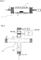
- brackets correspond to the numbers in Figures 1 and 2 , wherein (11) represents a processing chamber, (12) represents carbon nanotubes on the conductive metal substrate, (13) represents (means for supplying) sulphur-containing gas, (14) represents a heating element, such as an external heating coil, (15) represents a pressure gauge, (16) represents a vacuum pump, (21) represents another processing chamber, (22) represents a substrate holder, (23) represents a high-frequency plasma generator, such as a radio-frequency (RF) plasma generator, (24) represents a conductive metal coil, (25a) represents a conductive metal substrate, (25b) represents a conductive metal substrate with carbon nanotubes thereon, (26) represents means for supplying gas, (26a) represents carbon-containing gas, (26b) represents nitrogen-containing gas, (27) represents a pressure gauge and (28) represents a vacuum pump.
- (11) represents a processing chamber
- (12) represents carbon nanotubes on the conductive metal substrate
- (13) represents (means for supplying) sulphur-
- the invention concerns the first hybrid binder-free electrode for electrochemical energy storage devices, preferably for electrochemical supercapacitors, obtainable by or obtained by steps (a) - (g) of the methods as defined hereinbefore.
- the invention provides a first hybrid binder-free electrode for electrochemical energy storage devices, preferably for electrochemical supercapacitors, said first hybrid binder-free electrode comprising, preferably consisting of, a conductive metal substrate with carbon nanotubes having an average length of preferably 1 to 2 ⁇ m and an average diameter of preferably 50 to 100 nm attached thereto, wherein each carbon nanotube has only one single-crystal metal nanoparticle positioned at its tip with a metal nitride top layer, wherein the carbon nanotubes point in a direction perpendicular to the surface of the conductive metal substrate, wherein the metal of the single-crystal metal nanoparticles, the metal of the metal nitride layer and the metal of the conductive metal substrate are the same, and wherein the metal nitride layer on top of the single-crystal metal nanoparticle core is preferably in the form of layered thin-film structures, with a total layer thickness between 1 to 10 nm.
- the invention concerns the use of the first hybrid binder-free electrode as defined hereinbefore or the first hybrid binder-free electrode obtainable by or obtained by steps (a) - (g) of the methods as defined hereinbefore as or in an electrode for an electrochemical supercapacitor for high-frequency filtering applications, wherein said electrode preferably shows a phase angle above -75° and a capacitance above 400 ⁇ F at high-frequencies (above 100 Hz) with a cut-off frequency above 6000 Hz.
- the process as defined hereinbefore comprises additional steps that convert the first hybrid binder-free electrode obtained in step (g) to a second hybrid binder-free electrode for electrochemical energy storage devices, preferably for electrochemical supercapacitors, comprising, preferably consisting of, a conductive metal substrate (e.g., nickel) and carbon nanotubes attached to the conductive metal substrate, wherein each carbon nanotube has only one single-crystal metal nanoparticle positioned at its tip with a metal sulphide top layer, a single-crystal metal nanoparticle core and a metal nitride layer in between the metal sulphide top layer and the single-crystal metal nanoparticle core, the method comprising the following additional subsequent steps following step (g):
- the invention concerns the second hybrid binder-free electrode for electrochemical energy storage devices, preferably for electrochemical supercapacitors, obtainable by or obtained by steps (a) - (1) of the methods as defined hereinbefore.
- the invention provides a second hybrid binder-free electrode for electrochemical energy storage devices, preferably for electrochemical supercapacitors, said second hybrid binder-free electrode comprising, preferably consisting of, a conductive metal substrate with carbon nanotubes having an average length of preferably 1 to 2 ⁇ m and an average diameter of preferably 50 to 100 nm attached thereto, wherein each carbon nanotube has only one single-crystal metal nanoparticle positioned at its tip with a metal sulphide top layer, a single-crystal metal nanoparticle core and a metal nitride layer in between the metal sulphide top layer and the single-crystal metal nanoparticle core, wherein the carbon nanotubes point in a direction perpendicular to the surface of the conductive metal substrate, wherein the metal of the single-crystal metal nanoparticles, the metal of the metal nitride layer, the metal of the metal sulphide layer and the metal of the conductive metal substrate are the same, wherein the metal of the single-cry
- the invention concerns the use of the second hybrid binder-free electrode as defined hereinbefore or the second hybrid binder-free electrode obtainable by or obtained by steps (a) - (1) of the methods as defined hereinbefore as or in an electrode for a supercapacitor for electrochemical energy storage devices, wherein during charge-discharge cycling at a current density above 2 A ⁇ g -1 said electrode after many cycles (more than 4000) preferably delivers a specific capacity of above 800 C ⁇ g -1 , and wherein the specific capacity retains above 80 % of the initial specific capacity (more than 600 C ⁇ g -1 ) at higher current densities (more than 10 A ⁇ g -1 ).
- steps (b) - (g) are performed in the same processing chamber (21) as used in step (a). Accordingly, in a preferred embodiment, the invention concerns the method for manufacturing the first or second hybrid binder-free electrode for electrochemical energy storage devices, as defined hereinbefore, comprising the following subsequent steps:
- the carbon nanotubes grown in step (a) are preferably multi-walled carbon nanotubes. These carbon nanotubes have a length (largest dimension) and a diameter (smallest dimension).
- the carbon nanotubes are grown in a direction perpendicular to the surface of the conductive metal substrate. This means that the central axis of the carbon nanotubes, along the length or the largest dimension, points in a direction perpendicular to the surface of the conductive metal substrate.
- the average length of the carbon nanotubes grown in step (a) is preferably larger than 1 ⁇ m. More preferably, the average length of the carbon nanotubes grown in step (a) is between 1 and 2 ⁇ m.
- the average diameter of the carbon nanotubes grown in step (a) is preferably 100 nm or smaller. More preferably, the average diameter of the carbon nanotubes grown in step (a) is between 50 and 100 nm.
- the carbon nanotubes grown in step (a) have only one single-crystal metal nanoparticle positioned at their tips. This means a single-crystal metal nanoparticle positioned at the outer end of the carbon nanotube that is not attached to the conductive metal substrate.
- the metal nitride top layer formed in step (e) on the single-crystal metal nanoparticle preferably is in the form of thin layer nanostructures with a total layer thickness of between 1 to 10 nm, preferably between 3 and 7 nm, such as about 5 nm.
- the metal sulphide top layer formed in step (k) on the single-crystal metal nanoparticle preferably is in the form of single-crystalline nanostructures with individual crystallite sizes of between 50 and 100 nm.
- the inventors believe that the metal nitride layer serves as a diffusion layer for the metal from the single-crystal metal nanoparticle during the formation of the metal sulphide top layer. Accordingly, the metal sulphide is formed on top of the metal nitride instead of from conversion of the metal nitride to metal sulphide. Moreover, again without wishing to be bound by any theory, the inventors believe that the metal nitride layer serves as a single-crystal template, enabling the subsequent epitaxial growth of a single-crystal metal sulphide structure.
- the metal of the conductive metal substrate is preferably catalytic towards carbon nanotube synthesis.
- the metal of the conductive metal substrate has (substantial) carbon solubility.
- the metal of the conductive metal substrate is chosen from the group consisting of nickel, cobalt and copper.
- the metal of the conductive metal substrate is nickel and the metal nitride is nickel nitride (Ni 3 N). In another very preferred embodiment, the metal of the conductive metal substrate is nickel, the metal nitride is nickel nitride (Ni 3 N) and the metal sulphide is trinickel disulphide (Ni 3 S 2 ).
- the thickness of the conductive metal substrate is preferably 1 ⁇ m or more, more preferably about 25 ⁇ m.
- the conductive metal substrate can be a solid substrate, a porous substrate or a foam.
- processing chamber (11) is a long cylindrical quartz tube attached to a heating system, preferably an external heating coil.
- the metal of the single-crystal metal nanoparticles and the metal of the conductive metal substrate are the same.
- the metal nitride is formed in step (e) by contacting the metal of the single crystal metal nanoparticle with a nitrogen-containing plasma.
- the metal sulphide is formed in step (k) by contacting the metal of the single-crystal metal nanoparticles with a sulphur-containing gas.
- the metal in the metal sulphide and in the metal nitride is therefore also identical to the metal of the single-crystal metal nanoparticles and the metal of the conductive metal substrate.
- the nitrogen-containing gas applied in step (c) is selected from the group consisting of nitrogen, ammonia, and nitrogen dioxide. More preferably, the nitrogen-containing gas applied in step (c) is molecular nitrogen (N 2 ). Most preferably, the nitrogen-containing gas applied in step (c) is molecular nitrogen with a purity greater than 99 %, wherein the partial pressure of the molecular nitrogen inside the processing chamber is between 10 and 100 Pa, preferably between 10 and 30 Pa. Best results in terms of uniformity are obtained when only one gas is used.
- the interaction time in step (e) is between 5 and 105 s, preferably between 20 and 40 s, such as about 30 s, preferably applied in increments of 10 s with intermediate cooling.
- the plasma inside the processing chamber e.g. processing chamber (21) is created in step (d) at low power, preferably at a power of between 50 and 400 W, such as about 150 W.
- the high-frequency plasma generator (23), preferably a radio-frequency (RF) plasma generator (such as at 13.56 MHz), applied in step (d) is coupled, preferably using inductive coupling, to a conductive metal coil or antenna (24), preferably a copper coil or copper antenna, wrapped around the processing chamber (21).
- RF radio-frequency
- the processing chamber (21) preferably takes the form of a cross-type glass tube.
- the processing chamber (21) is a dielectric chamber with tubes made of borosilicate glass.
- the sulphur-containing gas (13) applied in step (i) is hydrogen sulphide (H 2 S) and the partial pressure of the sulphur-containing gas is between 8 ⁇ 10 4 and 9 ⁇ 10 4 Pa. Best results in terms of uniformity are obtained when only one gas is used.
- the interaction time in step (k) is between 30 and 240 minutes, preferably between 150 and 200 minutes.
- the carbon nanotubes are grown in step (a) using a vapour deposition tip-growth method.
- the carbon nanotubes are grown in step (a) using a plasma vapour deposition tip-growth method comprising the following steps:
- the growth of the carbon nanotubes in step (V) is performed continuously for a duration of between 1 and 60 minutes, preferably about 4 minutes.
- the carbon-containing gas (26a) applied in step (III) is preferably selected from the group consisting of methane, carbon dioxide, ethylene, and acetylene. More preferably, the carbon-containing gas (26a) in step (III) is methane. Most preferably, the carbon-containing gas (26a) in step (III) is methane with a purity greater than 99 % wherein the partial pressure of the methane inside the processing chamber (21) is between 20 and 60 Pa after the methane supply.
- the plasma inside the processing chamber (21) is created in step (IV) at high power, preferably between 500-1000 W.
- the high-frequency plasma generator (23), preferably a radio-frequency (RF) plasma generator (such as at 13.56 MHz), applied in step (IV) is coupled, preferably using inductive coupling, to a conductive metal coil or antenna (24), preferably a copper coil or copper antenna, wrapped around the processing chamber (21).
- RF radio-frequency
- the plasma vapour deposition tip-growth method is performed as follows.
- the conductive metal substrate (25a) is placed on a conductive substrate holder (22), which is electrically grounded during the process.
- the processing chamber (21) is evacuated to a pressure of below 10 Pa using a rotary vacuum pump (28).
- the pressure inside the processing chamber (21) is measured using a pressure gauge (27).
- Carbon-containing gas (26a) is supplied to the processing chamber (21) for the growth process and is fed through a mass flow controller (26) at a flow rate not less than 1 sccm.
- the plasma is created at a power typically not higher than 1000 W for the growth of the carbon nanotubes.
- the plasma vapour deposition tip-growth process typically lasts not less than 1 min.
- the processing chamber (21) and the conductive substrate holder (22) are not subjected to any external heating step during the growth process.
- the conductive substrate holder is heated due to the plasma heating effects during the growth itself.
- the conductive substrate holder (22) is taken out after the plasma vapour deposition tip-growth process and after the temperature of the substrate holder has dropped below a threshold temperature of below 35 °C.
- the method of the invention was applied to prepare a first hybrid binder-free electrode according to the invention.
- This example relates to the preparation of a binder-free electrode for electrochemical supercapacitors for high-frequency applications.
- metallic nickel foil with a thickness of 25 ⁇ m and a diameter of 14 mm was used as the conductive metal substrate.
- multi-walled carbon nanotubes wherein each carbon nanotube has only one single-crystal nickel nanoparticle positioned at its tip, were grown on the nickel foil using a plasma-assisted deposition system via a tip-growth mechanism.
- a setup as depicted in Figure 2 was used.
- the nickel foil as the conductive metal substrate (25a) was placed on a conductive substrate holder (22) inside a plasma processing chamber (21) made of borosilicate glass in the middle of a conductive metal coil (24) wrapped around the processing chamber (21).
- the conductive substrate holder (22) was electrically grounded during the growth.
- the processing chamber (21) was evacuated with a rotary vacuum pump (28) and a pressure gauge (27) to a pressure below 10 Pa.
- methane gas (26a) was leaked into the processing chamber (21) as the carbon precursor at a flow rate of 20 sccm through a mass flow controller (26). After supply of the methane gas (26a), the pressure inside the processing chamber was 30 Pa.
- an RF (13.56 MHz) plasma generator (23) was turned on at power 800 W.
- the RF plasma generator (23) was inductively coupled to the conductive metal coil (24).
- the RF plasma generator and the methane supply were turned off.
- the temperature of the sample holder reached 700-800 °C during the growth process due to the plasma heating effects.
- the temperature of the sample holder (22) was cooled to below a threshold temperature of 35 °C.
- the nickel foil with the grown carbon nanotubes thereon (25b) was exposed to nitrogen plasma-treatment in the same plasma processing chamber (21) in the middle of the conductive metal coil (24) wrapped around the processing chamber (21).
- the conductive substrate holder (22) was not electrically grounded.
- the processing chamber (21) was evacuated with a rotary vacuum pump (28) using a pressure gauge (27) to a pressure below 10 Pa.
- molecular nitrogen (N 2 ) gas (26b) was leaked into the processing chamber (21) as the treatment gas. After the supply of the nitrogen gas (26b), the pressure inside the processing chamber was 20 Pa.
- the RF (13.56 MHz) plasma generator (23) was turned on at a power 150 W and turned off after 10 s. After a cooling period of 10 s, the plasma generator (23) was turned on again at a power 150 W and turned off after 10 s. This process was repeated once again, and the nitrogen supply was turned off. Accordingly, the total effective plasma treating time was 30 s. After an additional 10 minutes, the processing chamber was vented and opened to take out the sample. Thus, a first hybrid binder-free electrode according to the invention was obtained.
- Figure 3(a) presents a TEM micrograph of an individual carbon nanotube obtained after the nitrogen plasma-treatment in the second step.
- the structure of the product is similar to the structure obtained after the first step, however, a layer of single-crystalline nickel nitride (Ni 3 N) was observed on top of the nickel nanoparticle.
- the resulting first hybrid binder-free electrode was used in an electrochemical setup for a supercapacitor and tested as an electrode for high-frequency filtering applications, and exhibited a phase angle above -75° and a capacitance above 400 ⁇ F at high-frequencies (above 100 Hz) with a cut-off frequency above 6000 Hz.
- the method of the invention was applied to prepare a second hybrid binder-free electrode according to the invention.
- This second example relates the preparation of a hybrid-binder-free electrode for electrochemical energy storage devices.
- the first hybrid binder-free electrode obtained in the second step of Example 1 was subjected to a third step.
- the nickel foil with the nitrogen plasma-treated carbon nanotubes (12) wherein each carbon nanotube has only one single-crystal metal nanoparticle covered with a single-crystalline nickel nitride layer positioned at its tip, was placed in a thermal treatment processing chamber (11), as depicted in Figure 1 , for the growth of nickel sulphide.
- the processing chamber (11) was evacuated to a pressure of below 1 Pa using a vacuum pump (16) and a pressure gauge (15).
- H 2 S hydrogen sulphide
- the temperature of the chamber was elevated to 125 °C at a rate of 6 °C/minutes using an external heating coil (14), and annealed for 180 minutes.
- the processing chamber (11) was let to cool down to room temperature, and the H 2 S gas was pumped out using the vacuum pump (16).
- the nickel sulphide successfully formed on top of the nickel nitride layer from the single-crystal nickel nanoparticle. The process resulted in a top layer of nickel sulphide on a single-crystal nickel nanoparticle core with a nickel nitride layer in between, without destroying the underlying carbon nanotubes.
- Figure 3(b) shows a TEM micrograph of the material obtained after the three steps.
- the nickel sulphide is only attached to the single-crystal nickel nanoparticle core covered with nickel nitride.
- the composite material consists of nickel sulphide, a nickel core and nickel nitride in between, carbon nanotubes and a nickel foil. There were no other sulphur-containing nanoparticles observed on the backbone of the carbon nanotube. As the nickel substrate was completely covered with carbon structures, it was not affected by the H 2 S gas.
- the nickel sulphide was formed from the single-crystal nickel nanoparticle on top of the nickel nitride layer in the form of single-crystalline nanostructures of Ni 3 S 2 .
- the obtained hybrid binder-free electrode is therefore confirmed as having a Ni 3 S 2 /Ni 3 N/Ni/carbon nanotube hybrid hierarchical structure.
- the second hybrid binder-free electrode was used as a supercapacitor and tested in an electrochemical test setup.
- the second hybrid binder-free electrode delivered during charge-discharge cycling at a current density above 2 A ⁇ g -1 after many cycles (more than 4000) a specific capacity of above 800 C ⁇ g -1 , and the specific capacity retained above 80 % of the initial specific capacity (more than 600 C ⁇ g -1 ) at higher current densities (more than 10 A ⁇ g -1 ).
Landscapes
- Engineering & Computer Science (AREA)
- Chemical & Material Sciences (AREA)
- Power Engineering (AREA)
- Nanotechnology (AREA)
- Materials Engineering (AREA)
- Organic Chemistry (AREA)
- Microelectronics & Electronic Packaging (AREA)
- Inorganic Chemistry (AREA)
- Crystallography & Structural Chemistry (AREA)
- Manufacturing & Machinery (AREA)
- Electric Double-Layer Capacitors Or The Like (AREA)
Priority Applications (1)
| Application Number | Priority Date | Filing Date | Title |
|---|---|---|---|
| EP20198712.0A EP3975213A1 (de) | 2020-09-28 | 2020-09-28 | Verfahren zur herstellung von hybriden bindemittelfreien elektroden für elektrochemische superkondensatoren |
Applications Claiming Priority (1)
| Application Number | Priority Date | Filing Date | Title |
|---|---|---|---|
| EP20198712.0A EP3975213A1 (de) | 2020-09-28 | 2020-09-28 | Verfahren zur herstellung von hybriden bindemittelfreien elektroden für elektrochemische superkondensatoren |
Publications (1)
| Publication Number | Publication Date |
|---|---|
| EP3975213A1 true EP3975213A1 (de) | 2022-03-30 |
Family
ID=72665128
Family Applications (1)
| Application Number | Title | Priority Date | Filing Date |
|---|---|---|---|
| EP20198712.0A Pending EP3975213A1 (de) | 2020-09-28 | 2020-09-28 | Verfahren zur herstellung von hybriden bindemittelfreien elektroden für elektrochemische superkondensatoren |
Country Status (1)
| Country | Link |
|---|---|
| EP (1) | EP3975213A1 (de) |
Citations (22)
| Publication number | Priority date | Publication date | Assignee | Title |
|---|---|---|---|---|
| WO1998014970A1 (en) | 1996-09-30 | 1998-04-09 | Pinnacle Research Institute, Inc. | High surface area metal nitrides or metal oxynitrides for electrical energy storage |
| US6168694B1 (en) | 1999-02-04 | 2001-01-02 | Chemat Technology, Inc. | Methods for and products of processing nanostructure nitride, carbonitride and oxycarbonitride electrode power materials by utilizing sol gel technology for supercapacitor applications |
| JP2003171108A (ja) * | 2001-12-03 | 2003-06-17 | Ricoh Co Ltd | カーボンナノチューブの作製方法 |
| US20030203139A1 (en) * | 1998-06-19 | 2003-10-30 | Zhifeng Ren | Free-standing and aligned carbon nanotubes and synthesis thereof |
| EP1547973A1 (de) | 2002-09-05 | 2005-06-29 | National Institute of Advanced Industrial Science and Technology | FEINES KOHLENSTOFFPULVER MIT METALLOXID-, METALLNITRID- ODER METALLCARBIDBESCHICHTUNG, HERSTELLUNGSVERFAHREN DAF R UND SUPERKONDENSATOR UND SEKUNDûRBATTERIE UNTER VERWENDUNG DES FEINEN KOHLENSTOFFPULVERS |
| WO2007053155A2 (en) | 2004-11-24 | 2007-05-10 | The Regents Of The University Of California | High power density supercapacitors with carbon nanotube electrodes |
| US20080232028A1 (en) | 2006-10-30 | 2008-09-25 | College Of William & Mary | Supercapacitor using carbon nanosheets as electrode |
| US20120154983A1 (en) | 2010-10-08 | 2012-06-21 | The Regents Of The University Of California | Method of Fabrication of Carbon Nanofibers on Nickel Foam |
| US20130074771A1 (en) * | 2009-09-18 | 2013-03-28 | Victor L. Pushparaj | Apparatus for forming energy storage and photovoltaic devices in a linear system |
| CN103208373A (zh) | 2012-01-16 | 2013-07-17 | 清华大学 | 石墨烯电极及其制备方法与应用 |
| US20140034906A1 (en) | 2011-12-27 | 2014-02-06 | Kabushiki Kaisha Toshiba | Carbon nanotube semiconductor devices and deterministic nanofabrication methods |
| US8971018B2 (en) | 2011-06-27 | 2015-03-03 | Sixpoint Materials, Inc. | Ultracapacitors using transition metal nitride-containing electrode and transition metal nitride |
| CN104867703A (zh) | 2015-06-04 | 2015-08-26 | 华东理工大学 | 一种制备金属硫化物/石墨烯/硫化镍复合薄膜材料的方法 |
| WO2015138038A2 (en) | 2013-12-20 | 2015-09-17 | Fastcap Systems Corporation | Ultracapacitors with high frequency response |
| US20150332868A1 (en) | 2012-04-14 | 2015-11-19 | Northeastern University | Flexible and Transparent Supercapacitors and Fabrication Using Thin Film Carbon Electrodes with Controlled Morphologies |
| US20150380174A1 (en) | 2008-10-21 | 2015-12-31 | Brookhaven Science Associates, Llc | Supercapacitors with Carbon Nanostructure Electrodes |
| CN105789624A (zh) | 2016-04-20 | 2016-07-20 | 浙江大学 | 阵列型二硫化三镍基复合电极及其制备方法和应用 |
| CN105895861A (zh) | 2016-04-20 | 2016-08-24 | 浙江大学 | 阵列型二硫化三镍-碳纳米管复合电极及其制备方法和应用 |
| CN105895882A (zh) | 2016-06-02 | 2016-08-24 | 广西大学 | 一种氮掺杂石墨烯包覆硫化镍复合电极材料的制备方法 |
| US9455094B2 (en) | 2011-11-18 | 2016-09-27 | William Marsh Rice University | Graphene-carbon nanotube hybrid materials and use as electrodes |
| RU2660819C1 (ru) * | 2017-08-17 | 2018-07-10 | Федеральное государственное бюджетное учреждение науки Институт нанотехнологий микроэлектроники Российской академии наук | Способ изготовления электрода суперконденсатора |
| CN110033959A (zh) * | 2019-03-29 | 2019-07-19 | 信阳师范学院 | 一种制备二硫化三镍杂化三维碳纳米管泡沫复合材料的方法 |
-
2020
- 2020-09-28 EP EP20198712.0A patent/EP3975213A1/de active Pending
Patent Citations (22)
| Publication number | Priority date | Publication date | Assignee | Title |
|---|---|---|---|---|
| WO1998014970A1 (en) | 1996-09-30 | 1998-04-09 | Pinnacle Research Institute, Inc. | High surface area metal nitrides or metal oxynitrides for electrical energy storage |
| US20030203139A1 (en) * | 1998-06-19 | 2003-10-30 | Zhifeng Ren | Free-standing and aligned carbon nanotubes and synthesis thereof |
| US6168694B1 (en) | 1999-02-04 | 2001-01-02 | Chemat Technology, Inc. | Methods for and products of processing nanostructure nitride, carbonitride and oxycarbonitride electrode power materials by utilizing sol gel technology for supercapacitor applications |
| JP2003171108A (ja) * | 2001-12-03 | 2003-06-17 | Ricoh Co Ltd | カーボンナノチューブの作製方法 |
| EP1547973A1 (de) | 2002-09-05 | 2005-06-29 | National Institute of Advanced Industrial Science and Technology | FEINES KOHLENSTOFFPULVER MIT METALLOXID-, METALLNITRID- ODER METALLCARBIDBESCHICHTUNG, HERSTELLUNGSVERFAHREN DAF R UND SUPERKONDENSATOR UND SEKUNDûRBATTERIE UNTER VERWENDUNG DES FEINEN KOHLENSTOFFPULVERS |
| WO2007053155A2 (en) | 2004-11-24 | 2007-05-10 | The Regents Of The University Of California | High power density supercapacitors with carbon nanotube electrodes |
| US20080232028A1 (en) | 2006-10-30 | 2008-09-25 | College Of William & Mary | Supercapacitor using carbon nanosheets as electrode |
| US20150380174A1 (en) | 2008-10-21 | 2015-12-31 | Brookhaven Science Associates, Llc | Supercapacitors with Carbon Nanostructure Electrodes |
| US20130074771A1 (en) * | 2009-09-18 | 2013-03-28 | Victor L. Pushparaj | Apparatus for forming energy storage and photovoltaic devices in a linear system |
| US20120154983A1 (en) | 2010-10-08 | 2012-06-21 | The Regents Of The University Of California | Method of Fabrication of Carbon Nanofibers on Nickel Foam |
| US8971018B2 (en) | 2011-06-27 | 2015-03-03 | Sixpoint Materials, Inc. | Ultracapacitors using transition metal nitride-containing electrode and transition metal nitride |
| US9455094B2 (en) | 2011-11-18 | 2016-09-27 | William Marsh Rice University | Graphene-carbon nanotube hybrid materials and use as electrodes |
| US20140034906A1 (en) | 2011-12-27 | 2014-02-06 | Kabushiki Kaisha Toshiba | Carbon nanotube semiconductor devices and deterministic nanofabrication methods |
| CN103208373A (zh) | 2012-01-16 | 2013-07-17 | 清华大学 | 石墨烯电极及其制备方法与应用 |
| US20150332868A1 (en) | 2012-04-14 | 2015-11-19 | Northeastern University | Flexible and Transparent Supercapacitors and Fabrication Using Thin Film Carbon Electrodes with Controlled Morphologies |
| WO2015138038A2 (en) | 2013-12-20 | 2015-09-17 | Fastcap Systems Corporation | Ultracapacitors with high frequency response |
| CN104867703A (zh) | 2015-06-04 | 2015-08-26 | 华东理工大学 | 一种制备金属硫化物/石墨烯/硫化镍复合薄膜材料的方法 |
| CN105789624A (zh) | 2016-04-20 | 2016-07-20 | 浙江大学 | 阵列型二硫化三镍基复合电极及其制备方法和应用 |
| CN105895861A (zh) | 2016-04-20 | 2016-08-24 | 浙江大学 | 阵列型二硫化三镍-碳纳米管复合电极及其制备方法和应用 |
| CN105895882A (zh) | 2016-06-02 | 2016-08-24 | 广西大学 | 一种氮掺杂石墨烯包覆硫化镍复合电极材料的制备方法 |
| RU2660819C1 (ru) * | 2017-08-17 | 2018-07-10 | Федеральное государственное бюджетное учреждение науки Институт нанотехнологий микроэлектроники Российской академии наук | Способ изготовления электрода суперконденсатора |
| CN110033959A (zh) * | 2019-03-29 | 2019-07-19 | 信阳师范学院 | 一种制备二硫化三镍杂化三维碳纳米管泡沫复合材料的方法 |
Non-Patent Citations (9)
| Title |
|---|
| ANIL KUMAR, Y.DASHA KUMAR, K.KIM, H. J.: "A novel electrode for supercapacitors: Efficient PVP-assisted synthesis of Ni3 S2 nanostructures grown on Ni foam for energy storage", DALT. TRANS., 2020 |
| CHEN, F.WANG, H.JI, S.LINKOV, V.WANG, R.: "High-performance all-solid-state asymmetric supercapacitors based on sponge-like NiS/Ni3S2 hybrid nanosheets", MATER. TODAY ENERGY, vol. 77, 2019, pages 211 - 217 |
| DAI CHAO-SHUAN ET AL: "Hierarchically Structured Ni 3 S 2 /Carbon Nanotube Composites as High Performance Cathode Materials for Asymmetric Supercapacitors", APPLIED MATERIALS & INTERFACES, vol. 5, no. 22, 18 November 2013 (2013-11-18), US, pages 12168 - 12174, XP055777358, ISSN: 1944-8244, Retrieved from the Internet <URL:https://pubs.acs.org/doi/pdf/10.1021/am404196s> DOI: 10.1021/am404196s * |
| MILLER, J. R.OUTLAW, R. A.HOLLOWAY, B. C.: "Graphene double-layer capacitor with ac line-filtering performance", SCIENCE, vol. 80, 2010 |
| NAMDARIAN, A.TABRIZI, A. G.MASELENO, A.MOHAMMADI, A.MOOSAVIFARD, S. E.: "One-step synthesis of rGO-Ni3S2 nano-cubes composite for high-performance supercapacitor electrodes", INT. J. HYDROGEN ENERGY, 2018 |
| RANGOM, Y.TANG, X. (SHIRLEYNAZAR, L. F.: "Carbon Nanotube-Based Supercapacitors with Excellent ac Line Filtering and Rate Capability via Improved Interfacial Impedance", ACS NANO, vol. 9, 2015, pages 7248 - 7255 |
| TIAN, Z.YIN, J.WANG, X.WANG, Y.: "Construction of Ni3S2 wrapped by rGO on carbon cloth for flexible supercapacitor application", J. ALLOYS COMPD., vol. 777, 2019, pages 806 - 811 |
| YOO, Y.KIM, M. S.KIM, J. K.KIM, Y. S.KIM, W.: "Fast-response supercapacitors with graphitic ordered mesoporous carbons and carbon nanotubes for AC line filtering", J. MATER. CHEM. A, 2016 |
| ZHANG, Z.ZHAO, C.MIN, S.QIAN, X.: "A facile one-step route to RGO/Ni3S2 for high-performance supercapacitors", ELECTROCHIM. ACTA, vol. 144, 2014, pages 100 - 110, XP029049726, DOI: 10.1016/j.electacta.2014.08.038 |
Similar Documents
| Publication | Publication Date | Title |
|---|---|---|
| Ge et al. | Multidimensional evolution of carbon structures underpinned by temperature‐induced intermediate of chloride for sodium‐ion batteries | |
| Zhang et al. | Vertically aligned graphene nanosheet arrays: synthesis, properties and applications in electrochemical energy conversion and storage | |
| Li et al. | From Commercial Sponge Toward 3D Graphene-Silicon Networks for Superior Lithium Storage. | |
| Saroja et al. | Facile synthesis of heteroatom doped and undoped graphene quantum dots as active materials for reversible lithium and sodium ions storage | |
| Sahoo et al. | A review on supercapacitors based on plasma enhanced chemical vapor deposited vertical graphene arrays | |
| Zhao et al. | High-performance Li-ion batteries based on graphene quantum dot wrapped carbon nanotube hybrid anodes | |
| Shah et al. | Electrochemical double layer capacitor electrodes using aligned carbon nanotubes grown directly on metals | |
| He et al. | Growth of carbon nanosheets on carbon nanotube arrays for the fabrication of three-dimensional micro-patterned supercapacitors | |
| CN102583339B (zh) | 三维多孔炭材料石墨烯化的方法及三维多孔石墨烯 | |
| Liu et al. | Leaf-inspired interwoven carbon nanosheet/nanotube homostructures for supercapacitors with high energy and power densities | |
| Cheng et al. | Synthesis and loading-dependent characteristics of nitrogen-doped graphene foam/carbon nanotube/manganese oxide ternary composite electrodes for high performance supercapacitors | |
| CN102263265A (zh) | 锂离子电池导电添加剂及其制备方法 | |
| Ren et al. | Self-supported graphene nanosheet-based composites as binder-free electrodes for advanced electrochemical energy conversion and storage | |
| CN102560415A (zh) | 三维石墨烯/金属线或金属丝复合结构及其制备方法 | |
| KR20120069704A (ko) | 배터리 애플리케이션용의 다공성 비정질 규소-탄소 나노튜브 복합물 기반 전극 | |
| Güneş | A direct synthesis of Si-nanowires on 3D porous graphene as a high performance anode material for Li-ion batteries | |
| CN102586869A (zh) | 三维石墨烯管及其制备方法 | |
| Zheng et al. | Large-scale synthesis of nitrogen-rich hierarchically porous carbon as anode for lithium-ion batteries with high capacity and rate capability | |
| JP2009078956A (ja) | カーボンナノチューブ複合体、これを用いたエネルギーデバイス及びカーボンナノチューブ複合体の製造方法 | |
| Oyedotun et al. | Graphene foam–based electrochemical capacitors | |
| Hong et al. | Microstructuring of carbon/tin quantum dots via a novel photolithography and pyrolysis-reduction process | |
| Mo et al. | N-doped mesoporous carbon nanosheets for supercapacitors with high performance | |
| Yun et al. | Holey graphene interpenetrating networks for boosting high-capacitive Co3O4 electrodes via an electrophoretic deposition process | |
| Wang et al. | One-pot spray pyrolysis for core–shell structured Sn@ SiOC anode nanocomposites that yield stable cycling in lithium-ion batteries | |
| Zeng et al. | Hierarchically porous graphene/wood-derived carbon activated using ZnCl 2 and decorated with in situ grown NiCo 2 O 4 for high–performance asymmetric supercapacitors |
Legal Events
| Date | Code | Title | Description |
|---|---|---|---|
| PUAI | Public reference made under article 153(3) epc to a published international application that has entered the european phase |
Free format text: ORIGINAL CODE: 0009012 |
|
| STAA | Information on the status of an ep patent application or granted ep patent |
Free format text: STATUS: THE APPLICATION HAS BEEN PUBLISHED |
|
| AK | Designated contracting states |
Kind code of ref document: A1 Designated state(s): AL AT BE BG CH CY CZ DE DK EE ES FI FR GB GR HR HU IE IS IT LI LT LU LV MC MK MT NL NO PL PT RO RS SE SI SK SM TR |
|
| STAA | Information on the status of an ep patent application or granted ep patent |
Free format text: STATUS: REQUEST FOR EXAMINATION WAS MADE |
|
| 17P | Request for examination filed |
Effective date: 20220921 |
|
| RBV | Designated contracting states (corrected) |
Designated state(s): AL AT BE BG CH CY CZ DE DK EE ES FI FR GB GR HR HU IE IS IT LI LT LU LV MC MK MT NL NO PL PT RO RS SE SI SK SM TR |
|
| STAA | Information on the status of an ep patent application or granted ep patent |
Free format text: STATUS: EXAMINATION IS IN PROGRESS |
|
| 17Q | First examination report despatched |
Effective date: 20240524 |
|
| GRAP | Despatch of communication of intention to grant a patent |
Free format text: ORIGINAL CODE: EPIDOSNIGR1 |
|
| STAA | Information on the status of an ep patent application or granted ep patent |
Free format text: STATUS: GRANT OF PATENT IS INTENDED |
|
| RIC1 | Information provided on ipc code assigned before grant |
Ipc: C01B 32/168 20170101ALI20240812BHEP Ipc: H01G 11/36 20130101ALI20240812BHEP Ipc: H01G 11/86 20130101ALI20240812BHEP Ipc: C01B 25/00 20060101ALI20240812BHEP Ipc: C01B 32/158 20170101ALI20240812BHEP Ipc: C01B 32/16 20170101ALI20240812BHEP Ipc: H01G 11/28 20130101AFI20240812BHEP |