EP3974265B1 - Motor transmission unit for electronic parking brake device - Google Patents
Motor transmission unit for electronic parking brake device Download PDFInfo
- Publication number
- EP3974265B1 EP3974265B1 EP20198946.4A EP20198946A EP3974265B1 EP 3974265 B1 EP3974265 B1 EP 3974265B1 EP 20198946 A EP20198946 A EP 20198946A EP 3974265 B1 EP3974265 B1 EP 3974265B1
- Authority
- EP
- European Patent Office
- Prior art keywords
- board
- transmission unit
- motor transmission
- brake device
- parking brake
- Prior art date
- Legal status (The legal status is an assumption and is not a legal conclusion. Google has not performed a legal analysis and makes no representation as to the accuracy of the status listed.)
- Active
Links
Images






Classifications
-
- B—PERFORMING OPERATIONS; TRANSPORTING
- B60—VEHICLES IN GENERAL
- B60T—VEHICLE BRAKE CONTROL SYSTEMS OR PARTS THEREOF; BRAKE CONTROL SYSTEMS OR PARTS THEREOF, IN GENERAL; ARRANGEMENT OF BRAKING ELEMENTS ON VEHICLES IN GENERAL; PORTABLE DEVICES FOR PREVENTING UNWANTED MOVEMENT OF VEHICLES; VEHICLE MODIFICATIONS TO FACILITATE COOLING OF BRAKES
- B60T7/00—Brake-action initiating means
- B60T7/02—Brake-action initiating means for personal initiation
- B60T7/04—Brake-action initiating means for personal initiation foot actuated
- B60T7/045—Brake-action initiating means for personal initiation foot actuated with locking and release means, e.g. providing parking brake application
-
- B—PERFORMING OPERATIONS; TRANSPORTING
- B60—VEHICLES IN GENERAL
- B60T—VEHICLE BRAKE CONTROL SYSTEMS OR PARTS THEREOF; BRAKE CONTROL SYSTEMS OR PARTS THEREOF, IN GENERAL; ARRANGEMENT OF BRAKING ELEMENTS ON VEHICLES IN GENERAL; PORTABLE DEVICES FOR PREVENTING UNWANTED MOVEMENT OF VEHICLES; VEHICLE MODIFICATIONS TO FACILITATE COOLING OF BRAKES
- B60T13/00—Transmitting braking action from initiating means to ultimate brake actuator with power assistance or drive; Brake systems incorporating such transmitting means, e.g. air-pressure brake systems
- B60T13/74—Transmitting braking action from initiating means to ultimate brake actuator with power assistance or drive; Brake systems incorporating such transmitting means, e.g. air-pressure brake systems with electrical assistance or drive
-
- B—PERFORMING OPERATIONS; TRANSPORTING
- B60—VEHICLES IN GENERAL
- B60T—VEHICLE BRAKE CONTROL SYSTEMS OR PARTS THEREOF; BRAKE CONTROL SYSTEMS OR PARTS THEREOF, IN GENERAL; ARRANGEMENT OF BRAKING ELEMENTS ON VEHICLES IN GENERAL; PORTABLE DEVICES FOR PREVENTING UNWANTED MOVEMENT OF VEHICLES; VEHICLE MODIFICATIONS TO FACILITATE COOLING OF BRAKES
- B60T13/00—Transmitting braking action from initiating means to ultimate brake actuator with power assistance or drive; Brake systems incorporating such transmitting means, e.g. air-pressure brake systems
- B60T13/74—Transmitting braking action from initiating means to ultimate brake actuator with power assistance or drive; Brake systems incorporating such transmitting means, e.g. air-pressure brake systems with electrical assistance or drive
- B60T13/741—Transmitting braking action from initiating means to ultimate brake actuator with power assistance or drive; Brake systems incorporating such transmitting means, e.g. air-pressure brake systems with electrical assistance or drive acting on an ultimate actuator
-
- B—PERFORMING OPERATIONS; TRANSPORTING
- B60—VEHICLES IN GENERAL
- B60T—VEHICLE BRAKE CONTROL SYSTEMS OR PARTS THEREOF; BRAKE CONTROL SYSTEMS OR PARTS THEREOF, IN GENERAL; ARRANGEMENT OF BRAKING ELEMENTS ON VEHICLES IN GENERAL; PORTABLE DEVICES FOR PREVENTING UNWANTED MOVEMENT OF VEHICLES; VEHICLE MODIFICATIONS TO FACILITATE COOLING OF BRAKES
- B60T13/00—Transmitting braking action from initiating means to ultimate brake actuator with power assistance or drive; Brake systems incorporating such transmitting means, e.g. air-pressure brake systems
- B60T13/74—Transmitting braking action from initiating means to ultimate brake actuator with power assistance or drive; Brake systems incorporating such transmitting means, e.g. air-pressure brake systems with electrical assistance or drive
- B60T13/746—Transmitting braking action from initiating means to ultimate brake actuator with power assistance or drive; Brake systems incorporating such transmitting means, e.g. air-pressure brake systems with electrical assistance or drive and mechanical transmission of the braking action
-
- B—PERFORMING OPERATIONS; TRANSPORTING
- B60—VEHICLES IN GENERAL
- B60T—VEHICLE BRAKE CONTROL SYSTEMS OR PARTS THEREOF; BRAKE CONTROL SYSTEMS OR PARTS THEREOF, IN GENERAL; ARRANGEMENT OF BRAKING ELEMENTS ON VEHICLES IN GENERAL; PORTABLE DEVICES FOR PREVENTING UNWANTED MOVEMENT OF VEHICLES; VEHICLE MODIFICATIONS TO FACILITATE COOLING OF BRAKES
- B60T7/00—Brake-action initiating means
- B60T7/02—Brake-action initiating means for personal initiation
- B60T7/08—Brake-action initiating means for personal initiation hand actuated
- B60T7/10—Disposition of hand control
- B60T7/107—Disposition of hand control with electrical power assistance
-
- F—MECHANICAL ENGINEERING; LIGHTING; HEATING; WEAPONS; BLASTING
- F16—ENGINEERING ELEMENTS AND UNITS; GENERAL MEASURES FOR PRODUCING AND MAINTAINING EFFECTIVE FUNCTIONING OF MACHINES OR INSTALLATIONS; THERMAL INSULATION IN GENERAL
- F16D—COUPLINGS FOR TRANSMITTING ROTATION; CLUTCHES; BRAKES
- F16D55/00—Brakes with substantially-radial braking surfaces pressed together in axial direction, e.g. disc brakes
- F16D55/02—Brakes with substantially-radial braking surfaces pressed together in axial direction, e.g. disc brakes with axially-movable discs or pads pressed against axially-located rotating members
- F16D55/22—Brakes with substantially-radial braking surfaces pressed together in axial direction, e.g. disc brakes with axially-movable discs or pads pressed against axially-located rotating members by clamping an axially-located rotating disc between movable braking members, e.g. movable brake discs or brake pads
- F16D55/224—Brakes with substantially-radial braking surfaces pressed together in axial direction, e.g. disc brakes with axially-movable discs or pads pressed against axially-located rotating members by clamping an axially-located rotating disc between movable braking members, e.g. movable brake discs or brake pads with a common actuating member for the braking members
- F16D55/225—Brakes with substantially-radial braking surfaces pressed together in axial direction, e.g. disc brakes with axially-movable discs or pads pressed against axially-located rotating members by clamping an axially-located rotating disc between movable braking members, e.g. movable brake discs or brake pads with a common actuating member for the braking members the braking members being brake pads
- F16D55/226—Brakes with substantially-radial braking surfaces pressed together in axial direction, e.g. disc brakes with axially-movable discs or pads pressed against axially-located rotating members by clamping an axially-located rotating disc between movable braking members, e.g. movable brake discs or brake pads with a common actuating member for the braking members the braking members being brake pads in which the common actuating member is moved axially, e.g. floating caliper disc brakes
- F16D55/2265—Brakes with substantially-radial braking surfaces pressed together in axial direction, e.g. disc brakes with axially-movable discs or pads pressed against axially-located rotating members by clamping an axially-located rotating disc between movable braking members, e.g. movable brake discs or brake pads with a common actuating member for the braking members the braking members being brake pads in which the common actuating member is moved axially, e.g. floating caliper disc brakes the axial movement being guided by one or more pins engaging bores in the brake support or the brake housing
-
- F—MECHANICAL ENGINEERING; LIGHTING; HEATING; WEAPONS; BLASTING
- F16—ENGINEERING ELEMENTS AND UNITS; GENERAL MEASURES FOR PRODUCING AND MAINTAINING EFFECTIVE FUNCTIONING OF MACHINES OR INSTALLATIONS; THERMAL INSULATION IN GENERAL
- F16D—COUPLINGS FOR TRANSMITTING ROTATION; CLUTCHES; BRAKES
- F16D55/00—Brakes with substantially-radial braking surfaces pressed together in axial direction, e.g. disc brakes
- F16D55/02—Brakes with substantially-radial braking surfaces pressed together in axial direction, e.g. disc brakes with axially-movable discs or pads pressed against axially-located rotating members
- F16D55/22—Brakes with substantially-radial braking surfaces pressed together in axial direction, e.g. disc brakes with axially-movable discs or pads pressed against axially-located rotating members by clamping an axially-located rotating disc between movable braking members, e.g. movable brake discs or brake pads
- F16D55/228—Brakes with substantially-radial braking surfaces pressed together in axial direction, e.g. disc brakes with axially-movable discs or pads pressed against axially-located rotating members by clamping an axially-located rotating disc between movable braking members, e.g. movable brake discs or brake pads with a separate actuating member for each side
-
- F—MECHANICAL ENGINEERING; LIGHTING; HEATING; WEAPONS; BLASTING
- F16—ENGINEERING ELEMENTS AND UNITS; GENERAL MEASURES FOR PRODUCING AND MAINTAINING EFFECTIVE FUNCTIONING OF MACHINES OR INSTALLATIONS; THERMAL INSULATION IN GENERAL
- F16D—COUPLINGS FOR TRANSMITTING ROTATION; CLUTCHES; BRAKES
- F16D65/00—Parts or details
- F16D65/005—Components of axially engaging brakes not otherwise provided for
- F16D65/0068—Brake calipers
- F16D65/0075—Brake calipers assembled from a plurality of parts
-
- F—MECHANICAL ENGINEERING; LIGHTING; HEATING; WEAPONS; BLASTING
- F16—ENGINEERING ELEMENTS AND UNITS; GENERAL MEASURES FOR PRODUCING AND MAINTAINING EFFECTIVE FUNCTIONING OF MACHINES OR INSTALLATIONS; THERMAL INSULATION IN GENERAL
- F16D—COUPLINGS FOR TRANSMITTING ROTATION; CLUTCHES; BRAKES
- F16D65/00—Parts or details
- F16D65/14—Actuating mechanisms for brakes; Means for initiating operation at a predetermined position
- F16D65/16—Actuating mechanisms for brakes; Means for initiating operation at a predetermined position arranged in or on the brake
- F16D65/18—Actuating mechanisms for brakes; Means for initiating operation at a predetermined position arranged in or on the brake adapted for drawing members together, e.g. for disc brakes
- F16D65/183—Actuating mechanisms for brakes; Means for initiating operation at a predetermined position arranged in or on the brake adapted for drawing members together, e.g. for disc brakes with force-transmitting members arranged side by side acting on a spot type force-applying member
-
- F—MECHANICAL ENGINEERING; LIGHTING; HEATING; WEAPONS; BLASTING
- F16—ENGINEERING ELEMENTS AND UNITS; GENERAL MEASURES FOR PRODUCING AND MAINTAINING EFFECTIVE FUNCTIONING OF MACHINES OR INSTALLATIONS; THERMAL INSULATION IN GENERAL
- F16D—COUPLINGS FOR TRANSMITTING ROTATION; CLUTCHES; BRAKES
- F16D55/00—Brakes with substantially-radial braking surfaces pressed together in axial direction, e.g. disc brakes
- F16D2055/0004—Parts or details of disc brakes
- F16D2055/0016—Brake calipers
- F16D2055/002—Brake calipers assembled from a plurality of parts
-
- F—MECHANICAL ENGINEERING; LIGHTING; HEATING; WEAPONS; BLASTING
- F16—ENGINEERING ELEMENTS AND UNITS; GENERAL MEASURES FOR PRODUCING AND MAINTAINING EFFECTIVE FUNCTIONING OF MACHINES OR INSTALLATIONS; THERMAL INSULATION IN GENERAL
- F16D—COUPLINGS FOR TRANSMITTING ROTATION; CLUTCHES; BRAKES
- F16D55/00—Brakes with substantially-radial braking surfaces pressed together in axial direction, e.g. disc brakes
- F16D2055/0004—Parts or details of disc brakes
- F16D2055/0066—Brakes having more than one actuator on the same side of the disc
-
- F—MECHANICAL ENGINEERING; LIGHTING; HEATING; WEAPONS; BLASTING
- F16—ENGINEERING ELEMENTS AND UNITS; GENERAL MEASURES FOR PRODUCING AND MAINTAINING EFFECTIVE FUNCTIONING OF MACHINES OR INSTALLATIONS; THERMAL INSULATION IN GENERAL
- F16D—COUPLINGS FOR TRANSMITTING ROTATION; CLUTCHES; BRAKES
- F16D2121/00—Type of actuator operation force
- F16D2121/02—Fluid pressure
- F16D2121/04—Fluid pressure acting on a piston-type actuator, e.g. for liquid pressure
-
- F—MECHANICAL ENGINEERING; LIGHTING; HEATING; WEAPONS; BLASTING
- F16—ENGINEERING ELEMENTS AND UNITS; GENERAL MEASURES FOR PRODUCING AND MAINTAINING EFFECTIVE FUNCTIONING OF MACHINES OR INSTALLATIONS; THERMAL INSULATION IN GENERAL
- F16D—COUPLINGS FOR TRANSMITTING ROTATION; CLUTCHES; BRAKES
- F16D2121/00—Type of actuator operation force
- F16D2121/18—Electric or magnetic
- F16D2121/24—Electric or magnetic using motors
-
- F—MECHANICAL ENGINEERING; LIGHTING; HEATING; WEAPONS; BLASTING
- F16—ENGINEERING ELEMENTS AND UNITS; GENERAL MEASURES FOR PRODUCING AND MAINTAINING EFFECTIVE FUNCTIONING OF MACHINES OR INSTALLATIONS; THERMAL INSULATION IN GENERAL
- F16D—COUPLINGS FOR TRANSMITTING ROTATION; CLUTCHES; BRAKES
- F16D2125/00—Components of actuators
- F16D2125/18—Mechanical mechanisms
- F16D2125/20—Mechanical mechanisms converting rotation to linear movement or vice versa
- F16D2125/34—Mechanical mechanisms converting rotation to linear movement or vice versa acting in the direction of the axis of rotation
- F16D2125/40—Screw-and-nut
Definitions
- the present invention relates to a motor transmission unit for an electronic parking brake device for vehicles.
- the conventional motor transmission unit for vehicle electronic parking brake device is disclosed in TW 104214409 and includes a motor whose output shaft is co-rotatably connected with a pivotal transmission shaft to drive an eccentric shaft.
- the eccentric end of the eccentric shaft is located in and restricted by a recess of a push rod, so that when the transmission shaft drives the eccentric shaft, the eccentric shaft can only move toward a direction away from the transmission shaft such that the eccentric shaft is not co-rotated with the transmission shaft.
- the push rod pushes the first lining plate and contacts one side of the brake disk.
- the transmission shaft drives the cap toward a direction away from the first lateral part, such that the guide board of the cap moves and push the second lining plate to contact the other side of the brake disk to complete electronic parking action by the motor.
- the eccentric end has to continuously contact against the inside of the recess of the push rod so as to ensure that the eccentric rod does not rotate and to move linearly relative to the transmission shaft.
- the eccentric rod cannot avoid from slightly shaking and swinging.
- the eccentric rod also applies a force to the seal ring during the shanking and swinging action, and this reduces the life of the seal ring which tends to be deformed quickly.
- the brake oil may leak from the deformed seal ring.
- the present invention intends to provide a motor transmission unit for an electronic parking brake device for vehicles to eliminate shortcomings mentioned above.
- the present invention is defined in claim 1 and relates to a motor transmission unit for an electronic parking brake device, and comprises a case, a driving member, a board, a rod and a push unit.
- the case is slidably mounted, through a cap, on a clamp.
- the case includes a passage which is open toward the cap.
- the driving member is inserted into the case and partially located in the passage of the case.
- the board is threadedly mounted to the driving member and located in the passage.
- the board includes a first end face and a second end face, wherein the first end face faces the passage.
- the rod is located between an inner periphery of the passage and the board.
- the push unit includes a first end thereof contacting the first end face, and a second end that is inserted in the clamp.
- a seal ring is mounted to the push unit.
- a portion of the second end of the push unit is located in a chamber of the clamp and contacts a piston.
- the board moves axially along the driving member and toward the clamp.
- the board is restricted by the rod and does not rotate.
- the first end face of the board pushes the push unit which moves axially, and moves the piston to push a lining plate of the clamp to contact a brake disk.
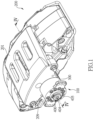
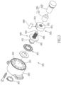
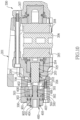
- the show the motor transmission unit 100 for an electronic parking brake device of the present invention comprises a case 300, a driving member 400, a board 500, a rod 600 and a push unit 700.
- the case 300 is slidably mounted, through the left side 209 of a cap 201, on a clamp 200.
- the case 300 includes a passage 301 which opens toward the cap 201.
- the driving member 400 is inserted into the case 300 and partially located in the passage 301 of the case 300.
- the board 500 is threadedly mounted to the driving member 400 and located in the passage 301.
- the board 500 includes a first end face 501 and a second end face 504 which is located opposite to the first end face 501.
- the first end face 501 faces the passage 301.
- the rod 600 is located between the inner periphery of the passage 301 and the board 500.
- the push unit 700 includes a first end thereof contacting the first end face 501, and a second end of the push unit 700 is inserted in the clamp 200.
- a seal ring 202 is mounted to the push unit 700.
- a portion of the second end of the push unit 700 is located in a chamber 203 of the clamp 200 and contacts a piston 204.
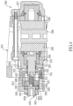
- the board 500 moves axially along the driving member 400 and toward the clamp 200.
- the board 500 is restricted by the rod 600 and does not rotate.
- the first end face 501 of the board 500 pushes the push unit 700 which moves axially and moves the piston 204 to push a lining plate 205 of the clamp 200 to contact a brake disk 206.
- the board 500 is restricted by the rod 600 so that the board 500 can only move along the driving member 400 and does not rotate. Therefore, the board 500 directly pushes the push unit 700 to move axially, and the push unit 700 pushes the lining plate 205 of the clamp 200 to contact the brake disk 206 to stop the vehicle. Because the push unit 700 does not rotate and swing, so that the seal ring 202 is not deformed and twisted to achieve the purpose of the present invention.
- the push unit 700 is moved by the driving member 400 so that the driving member 400 drives the cap 201 to move toward the left side in the drawing, and the right side 207 of the cap 201 pushes the lining plate 208 to contact the brake disk 206 to park the vehicle. When the motor is operated to rotate in opposite direction, the brake action is released.
- the driving member 400 includes a fist section 401 and a second section 402, and a flange 403 is located between the first and second sections 401, 402.
- the first section 401 extends through the case 300.
- the flange 403 is located in the passage 301.
- the board 500 is threadedly connected to the second section 402.
- the diameter of the flange 403 is larger than that of each of the first and second sections 401, 402.
- the flange 403 prevents the driving member 400 from dropping from the passage 301.
- the first section 401 includes a recess 404 to which an output shaft of a motor (both not shown) is connected.
- a clip 405 is mounted to outside of the first section 401 to restrict the driving member 400 from dropping from the passage 301.
- the second section 402 of the driving member 400 includes outer threads 406 defined in the outer periphery thereof.
- the board 500 includes inner threads 502 which are threadedly connected to the outer threads 406. It is noted that the outer threads 406 and the inner threads 502 both have double threads so that the board 500 can move fast.
- a needle roller thrush bearing 801 is mounted to the first section 401 of the driving member 40.
- the needle roller thrush bearing 801 is located between the inner periphery of the passage 301 and the flange 403.
- the needle roller thrush bearing 801 avoids the flange 403 from contacting the inner periphery of the passage 301 so that the flange 403 rotates smoothly.
- a first slot 302 is defined in the inner periphery of the passage 301.
- a second slot 503 is defined in the outer periphery of the board 500, so that the rod 600 is accommodated between the first and second slots 302, 503.
- the rod 600 is a round cylindrical rod, and the first and second slots 302, 503 form a space which is shaped to accommodate the rod 600. Therefore, the rod 600 keeps the board 500 to move axially and does not rotate.
- the push unit 700 includes a first part 701 and a second part 702 which is connected to the first part 701.
- the first part 701 contacts the first end face 501, and the second part 702 contacts the piston 204.
- the seal ring 202 of the clamp 200 is mounted to the second part 702.
- the first part 701 and the second part 702 are connected in a protrusion-and-recess pattern.
- the first part 701 includes a room 703 defined in an end thereof which contacts the first end face 501 of the board 500.
- the second section 402 does not contact the inside of the room 703.
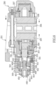
- the push unit 700 includes a shank 704 and a head 705 which is formed to the shank 704.
- the seal ring 202 of the clamp 200 is mounted to the shank 704, and the head 705 contacts the piston 204.
- the shank 704 and the head 705 are two individual parts and are connected each other by any known method such as welding.
- the head 705 is eccentrically located relative to the shank 704.
- the shank 704 includes a room 706 defined in the distal end opposite to the head 705.
- the distal end of the shank 704 contacts the first end face 501 of the board 500.
- the second section 402 of the driving member 400 is located in the room 706 of the shank 704 and is not in contact with an inside of the room 706.
- the third embodiment is disclosed, the difference between the second and the third embodiments is that the head 705 is co-axially located relative to the shank 704.
- Another needle roller thrush bearing 802 is mounted to the second section 402 of the driving member 40.
- the another needle roller thrush bearing 802 is located between the second end face 504 of the board 500 and the flange 403.
- the board 500 and the driving member 400 are threadedly connected to each other, and the threads of the board 500 and the driving member 400 are single thread.
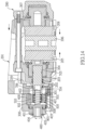
- the fourth embodiment is disclosed, the difference between the third and the fourth embodiments is that the second section 402 of the driving member 400 includes a groove 407 spirally defined in the outer periphery thereof.
- the board 500 includes balls 505 which are movably received in the groove 407.
Landscapes
- Engineering & Computer Science (AREA)
- Mechanical Engineering (AREA)
- General Engineering & Computer Science (AREA)
- Transportation (AREA)
- Braking Arrangements (AREA)
Priority Applications (4)
| Application Number | Priority Date | Filing Date | Title |
|---|---|---|---|
| ES20198946T ES2958184T3 (es) | 2020-09-29 | 2020-09-29 | Unidad de transmisión de motor para dispositivo electrónico de freno de estacionamiento |
| HUE20198946A HUE064009T2 (hu) | 2020-09-29 | 2020-09-29 | Motoros erõátviteli egység elektronikus rögzítõfékhez |
| EP20198946.4A EP3974265B1 (en) | 2020-09-29 | 2020-09-29 | Motor transmission unit for electronic parking brake device |
| PL20198946.4T PL3974265T3 (pl) | 2020-09-29 | 2020-09-29 | Zespół przeniesienia napędu dla elektronicznego hamulca postojowego |
Applications Claiming Priority (1)
| Application Number | Priority Date | Filing Date | Title |
|---|---|---|---|
| EP20198946.4A EP3974265B1 (en) | 2020-09-29 | 2020-09-29 | Motor transmission unit for electronic parking brake device |
Publications (3)
| Publication Number | Publication Date |
|---|---|
| EP3974265A1 EP3974265A1 (en) | 2022-03-30 |
| EP3974265B1 true EP3974265B1 (en) | 2023-08-30 |
| EP3974265C0 EP3974265C0 (en) | 2023-08-30 |
Family
ID=72670562
Family Applications (1)
| Application Number | Title | Priority Date | Filing Date |
|---|---|---|---|
| EP20198946.4A Active EP3974265B1 (en) | 2020-09-29 | 2020-09-29 | Motor transmission unit for electronic parking brake device |
Country Status (4)
| Country | Link |
|---|---|
| EP (1) | EP3974265B1 (pl) |
| ES (1) | ES2958184T3 (pl) |
| HU (1) | HUE064009T2 (pl) |
| PL (1) | PL3974265T3 (pl) |
Families Citing this family (1)
| Publication number | Priority date | Publication date | Assignee | Title |
|---|---|---|---|---|
| CN112298126B (zh) * | 2019-08-01 | 2024-04-16 | 汉拿万都株式会社 | 一种车辆卡钳、车辆的制动方法及车辆 |
Family Cites Families (7)
| Publication number | Priority date | Publication date | Assignee | Title |
|---|---|---|---|---|
| DE102008018749A1 (de) * | 2007-09-12 | 2009-03-26 | Continental Teves Ag & Co. Ohg | Verfahren zum gesicherten Lösen einer elektromechanisch betätigbaren Feststellbremse |
| JP5407996B2 (ja) * | 2010-03-31 | 2014-02-05 | 株式会社アドヴィックス | 車両用ブレーキ制御装置 |
| KR101407468B1 (ko) * | 2010-05-12 | 2014-06-16 | 주식회사 만도 | 전자식 주차 브레이크 시스템 |
| CN201872738U (zh) * | 2010-10-27 | 2011-06-22 | 浙江中昌汽车零部件有限公司 | 电子驻车制动器 |
| KR20120060069A (ko) * | 2010-12-01 | 2012-06-11 | 현대자동차주식회사 | 차량용 전기식 주차 브레이크 장치 |
| JP2013189027A (ja) * | 2012-03-12 | 2013-09-26 | Advics Co Ltd | 車両用ブレーキ制御装置 |
| US9850971B1 (en) * | 2016-08-03 | 2017-12-26 | Mando Corporation | Disk brake piston |
-
2020
- 2020-09-29 PL PL20198946.4T patent/PL3974265T3/pl unknown
- 2020-09-29 ES ES20198946T patent/ES2958184T3/es active Active
- 2020-09-29 HU HUE20198946A patent/HUE064009T2/hu unknown
- 2020-09-29 EP EP20198946.4A patent/EP3974265B1/en active Active
Also Published As
| Publication number | Publication date |
|---|---|
| HUE064009T2 (hu) | 2024-02-28 |
| EP3974265C0 (en) | 2023-08-30 |
| PL3974265T3 (pl) | 2023-10-30 |
| EP3974265A1 (en) | 2022-03-30 |
| ES2958184T3 (es) | 2024-02-05 |
Similar Documents
| Publication | Publication Date | Title |
|---|---|---|
| JP6928721B2 (ja) | 電気液圧式のサーボブレーキの一体型の液圧モジュール | |
| US6076382A (en) | Steering lock drive | |
| EP3974265B1 (en) | Motor transmission unit for electronic parking brake device | |
| JP7816262B2 (ja) | ボールねじ装置 | |
| CN113883113B (zh) | 电磁阀 | |
| JP2004106181A5 (pl) | ||
| JP7439648B2 (ja) | ボールねじ装置 | |
| EP1925836B1 (en) | Torque transmission and limiting device | |
| US8156846B2 (en) | Release device of extension rod assembly | |
| JP2008512297A (ja) | 自動車用ステアリングスピンドルロック装置 | |
| US11313425B2 (en) | Motor transmission unit for electronic parking brake device | |
| JP2553818B2 (ja) | クラッチハブ | |
| CN117182555B (zh) | 一种制动器安装方法及装置 | |
| JP7403702B1 (ja) | クラッチ装置 | |
| CN1108164A (zh) | 设置在手持式工作机械上并且可使工具转动联动的装置 | |
| US20160059401A1 (en) | Power tool | |
| WO2024009760A1 (ja) | クラッチ装置および自動二輪車 | |
| JP2009024722A (ja) | フライホイール装置 | |
| CN118958813A (zh) | 驱动组件 | |
| JP2007092932A (ja) | 等速自在継手のシャフト抜け止め構造 | |
| US6817259B2 (en) | Steering gear for motor vehicles | |
| JP2024006005A (ja) | クラッチ装置および自動二輪車 | |
| JP5726840B2 (ja) | チェックバルブ機構におけるスプリングの支持構造 | |
| KR20170110756A (ko) | 전자식 주차 브레이크용 액추에이터 | |
| WO2026040843A1 (zh) | 用于盘式制动器的致动装置和盘式制动器 |
Legal Events
| Date | Code | Title | Description |
|---|---|---|---|
| PUAI | Public reference made under article 153(3) epc to a published international application that has entered the european phase |
Free format text: ORIGINAL CODE: 0009012 |
|
| STAA | Information on the status of an ep patent application or granted ep patent |
Free format text: STATUS: REQUEST FOR EXAMINATION WAS MADE |
|
| 17P | Request for examination filed |
Effective date: 20201027 |
|
| AK | Designated contracting states |
Kind code of ref document: A1 Designated state(s): AL AT BE BG CH CY CZ DE DK EE ES FI FR GB GR HR HU IE IS IT LI LT LU LV MC MK MT NL NO PL PT RO RS SE SI SK SM TR |
|
| GRAP | Despatch of communication of intention to grant a patent |
Free format text: ORIGINAL CODE: EPIDOSNIGR1 |
|
| STAA | Information on the status of an ep patent application or granted ep patent |
Free format text: STATUS: GRANT OF PATENT IS INTENDED |
|
| INTG | Intention to grant announced |
Effective date: 20230515 |
|
| GRAS | Grant fee paid |
Free format text: ORIGINAL CODE: EPIDOSNIGR3 |
|
| GRAA | (expected) grant |
Free format text: ORIGINAL CODE: 0009210 |
|
| STAA | Information on the status of an ep patent application or granted ep patent |
Free format text: STATUS: THE PATENT HAS BEEN GRANTED |
|
| AK | Designated contracting states |
Kind code of ref document: B1 Designated state(s): AL AT BE BG CH CY CZ DE DK EE ES FI FR GB GR HR HU IE IS IT LI LT LU LV MC MK MT NL NO PL PT RO RS SE SI SK SM TR |
|
| REG | Reference to a national code |
Ref country code: GB Ref legal event code: FG4D |
|
| REG | Reference to a national code |
Ref country code: CH Ref legal event code: EP |
|
| REG | Reference to a national code |
Ref country code: DE Ref legal event code: R096 Ref document number: 602020016587 Country of ref document: DE |
|
| REG | Reference to a national code |
Ref country code: IE Ref legal event code: FG4D |
|
| REG | Reference to a national code |
Ref country code: NO Ref legal event code: T2 Effective date: 20230830 |
|
| U01 | Request for unitary effect filed |
Effective date: 20230908 |
|
| U07 | Unitary effect registered |
Designated state(s): AT BE BG DE DK EE FI FR IT LT LU LV MT NL PT SE SI Effective date: 20230913 |
|
| U20 | Renewal fee for the european patent with unitary effect paid |
Year of fee payment: 4 Effective date: 20230908 |
|
| REG | Reference to a national code |
Ref country code: GR Ref legal event code: EP Ref document number: 20230401946 Country of ref document: GR Effective date: 20231211 |
|
| PG25 | Lapsed in a contracting state [announced via postgrant information from national office to epo] |
Ref country code: IS Free format text: LAPSE BECAUSE OF FAILURE TO SUBMIT A TRANSLATION OF THE DESCRIPTION OR TO PAY THE FEE WITHIN THE PRESCRIBED TIME-LIMIT Effective date: 20231230 |
|
| PG25 | Lapsed in a contracting state [announced via postgrant information from national office to epo] |
Ref country code: RS Free format text: LAPSE BECAUSE OF FAILURE TO SUBMIT A TRANSLATION OF THE DESCRIPTION OR TO PAY THE FEE WITHIN THE PRESCRIBED TIME-LIMIT Effective date: 20230830 Ref country code: IS Free format text: LAPSE BECAUSE OF FAILURE TO SUBMIT A TRANSLATION OF THE DESCRIPTION OR TO PAY THE FEE WITHIN THE PRESCRIBED TIME-LIMIT Effective date: 20231230 Ref country code: HR Free format text: LAPSE BECAUSE OF FAILURE TO SUBMIT A TRANSLATION OF THE DESCRIPTION OR TO PAY THE FEE WITHIN THE PRESCRIBED TIME-LIMIT Effective date: 20230830 |
|
| REG | Reference to a national code |
Ref country code: HU Ref legal event code: AG4A Ref document number: E064009 Country of ref document: HU |
|
| PG25 | Lapsed in a contracting state [announced via postgrant information from national office to epo] |
Ref country code: SM Free format text: LAPSE BECAUSE OF FAILURE TO SUBMIT A TRANSLATION OF THE DESCRIPTION OR TO PAY THE FEE WITHIN THE PRESCRIBED TIME-LIMIT Effective date: 20230830 Ref country code: RO Free format text: LAPSE BECAUSE OF FAILURE TO SUBMIT A TRANSLATION OF THE DESCRIPTION OR TO PAY THE FEE WITHIN THE PRESCRIBED TIME-LIMIT Effective date: 20230830 Ref country code: SK Free format text: LAPSE BECAUSE OF FAILURE TO SUBMIT A TRANSLATION OF THE DESCRIPTION OR TO PAY THE FEE WITHIN THE PRESCRIBED TIME-LIMIT Effective date: 20230830 |
|
| PG25 | Lapsed in a contracting state [announced via postgrant information from national office to epo] |
Ref country code: MC Free format text: LAPSE BECAUSE OF FAILURE TO SUBMIT A TRANSLATION OF THE DESCRIPTION OR TO PAY THE FEE WITHIN THE PRESCRIBED TIME-LIMIT Effective date: 20230830 |
|
| REG | Reference to a national code |
Ref country code: DE Ref legal event code: R097 Ref document number: 602020016587 Country of ref document: DE |
|
| PLBE | No opposition filed within time limit |
Free format text: ORIGINAL CODE: 0009261 |
|
| STAA | Information on the status of an ep patent application or granted ep patent |
Free format text: STATUS: NO OPPOSITION FILED WITHIN TIME LIMIT |
|
| 26N | No opposition filed |
Effective date: 20240603 |
|
| U20 | Renewal fee for the european patent with unitary effect paid |
Year of fee payment: 5 Effective date: 20240808 |
|
| PG25 | Lapsed in a contracting state [announced via postgrant information from national office to epo] |
Ref country code: CY Free format text: LAPSE BECAUSE OF FAILURE TO SUBMIT A TRANSLATION OF THE DESCRIPTION OR TO PAY THE FEE WITHIN THE PRESCRIBED TIME-LIMIT; INVALID AB INITIO Effective date: 20200929 |
|
| U20 | Renewal fee for the european patent with unitary effect paid |
Year of fee payment: 6 Effective date: 20250728 |
|
| REG | Reference to a national code |
Ref country code: CH Ref legal event code: U11 Free format text: ST27 STATUS EVENT CODE: U-0-0-U10-U11 (AS PROVIDED BY THE NATIONAL OFFICE) Effective date: 20251001 |
|
| PGFP | Annual fee paid to national office [announced via postgrant information from national office to epo] |
Ref country code: NO Payment date: 20250807 Year of fee payment: 6 Ref country code: GR Payment date: 20250807 Year of fee payment: 6 |
|
| PGFP | Annual fee paid to national office [announced via postgrant information from national office to epo] |
Ref country code: TR Payment date: 20250922 Year of fee payment: 6 Ref country code: PL Payment date: 20250801 Year of fee payment: 6 |
|
| PGFP | Annual fee paid to national office [announced via postgrant information from national office to epo] |
Ref country code: HU Payment date: 20250827 Year of fee payment: 6 Ref country code: GB Payment date: 20250801 Year of fee payment: 6 |
|
| PGFP | Annual fee paid to national office [announced via postgrant information from national office to epo] |
Ref country code: IE Payment date: 20250728 Year of fee payment: 6 Ref country code: CZ Payment date: 20250729 Year of fee payment: 6 |
|
| PGFP | Annual fee paid to national office [announced via postgrant information from national office to epo] |
Ref country code: CH Payment date: 20251001 Year of fee payment: 6 |
|
| PGFP | Annual fee paid to national office [announced via postgrant information from national office to epo] |
Ref country code: ES Payment date: 20251001 Year of fee payment: 6 |