EP3973613B1 - Stator einer elektrischen maschine - Google Patents
Stator einer elektrischen maschine Download PDFInfo
- Publication number
- EP3973613B1 EP3973613B1 EP20723098.8A EP20723098A EP3973613B1 EP 3973613 B1 EP3973613 B1 EP 3973613B1 EP 20723098 A EP20723098 A EP 20723098A EP 3973613 B1 EP3973613 B1 EP 3973613B1
- Authority
- EP
- European Patent Office
- Prior art keywords
- tooth
- stator
- head
- base
- limb
- Prior art date
- Legal status (The legal status is an assumption and is not a legal conclusion. Google has not performed a legal analysis and makes no representation as to the accuracy of the status listed.)
- Active
Links
Images

Classifications
-
- H—ELECTRICITY
- H02—GENERATION; CONVERSION OR DISTRIBUTION OF ELECTRIC POWER
- H02K—DYNAMO-ELECTRIC MACHINES
- H02K1/00—Details of the magnetic circuit
- H02K1/06—Details of the magnetic circuit characterised by the shape, form or construction
- H02K1/12—Stationary parts of the magnetic circuit
- H02K1/14—Stator cores with salient poles
- H02K1/146—Stator cores with salient poles consisting of a generally annular yoke with salient poles
-
- H—ELECTRICITY
- H02—GENERATION; CONVERSION OR DISTRIBUTION OF ELECTRIC POWER
- H02K—DYNAMO-ELECTRIC MACHINES
- H02K2213/00—Specific aspects, not otherwise provided for and not covered by codes H02K2201/00 - H02K2211/00
- H02K2213/03—Machines characterised by numerical values, ranges, mathematical expressions or similar information
Definitions
- the present invention relates to a stator of an electrical machine.
- the invention also relates to an electrical machine comprising such a stator.
- the stator usually has a large number of stator teeth, with tooth heads being arranged at the ends of the stator teeth.
- the tooth heads can have different characteristics. For example, the in DE 10 2008 026 756 B4 , the US 6,288,471 A , the US 6,984,909 A , as well as those in US 2006/038458 A1 each with different designs of tooth heads.
- the stator of an electrical machine has trapezoidal tooth heads which are arranged asymmetrically.
- the trapezoidal shape reduces current heat losses in that electrical conductor of a winding of the stator that rests on the tooth head.
- losses caused by magnetic flux leakage between the tooth heads are reduced.
- the asymmetry of the tooth head also ensures that favorable properties are created with regard to slot insulation with overlapping insulation paper, whereby an effective tooth head width decreases and thus the leakage flux is reduced, while the performance of the electrical machine with the stator is increased.
- an acoustically effective small tangential tooth tip width can be achieved. This makes it acoustic Behavior, especially with regard to tonality and sound power level, is optimized and torque ripple is reduced.
- the stator of an electrical machine has a stator yoke which extends in a ring around a stator axis.
- the stator has stator teeth extending radially from the stator yoke and along a respective tooth axis, each stator tooth being arranged with a first end on the stator yoke.
- a tooth head is formed at a second end opposite the first end.
- the first end corresponds to a proximal end of the stator tooth, with the second end corresponding to a distal end of the stator tooth.
- Stator tooth, stator yoke and tooth head are advantageously all made of the same material, in particular in one piece.
- the stator yoke, stator teeth and tooth heads are made of a magnetically conductive material.
- the tooth head has in particular two tooth head projections, each of which projects transversely to the tooth axis relative to the remaining stator tooth, forming a tooth head step.
- the tooth head of the stator teeth is trapezoidal, in particular with a trapezoidal cross section. This cross section lies in particular in a plane perpendicular to the stator axis.
- each tooth tip is designed asymmetrically with respect to the respective tooth axis. In this way, the advantages described above can be achieved. An asymmetrical arrangement occurs in particular when tooth tip projections in the tangential direction or in the circumferential direction with respect to the stator axis are different with respect to the outer surfaces of the stator tooth.
- the two tooth head projections of the same tooth head are preferably designed to be of different lengths.
- the different lengths of the two tooth head projections are measured in particular in the same plane perpendicular to the tooth axis, in particular at the step of the tooth head.
- the trapezoidal shape of the respective tooth heads has a base facing the tooth head step, a base side facing away from the tooth head step and a first leg and a second leg.
- the first leg and the second leg each extend between the base and the base side.
- the two legs particularly advantageously assume different angles to the base in terms of magnitude. It is also intended that the base is longer than the base side.
- the base and the base side are oriented parallel to one another, with the first leg and the second leg preferably not running parallel to one another.
- a trapezoidal shape is therefore present. It is further provided that the base rests on the second end of the stator tooth. Due to such an orientation of the trapezoidal shape, the properties and advantages described above can be achieved in a particularly advantageous manner.
- a first tooth tip projection which corresponds to the portion of the base between the first leg and the stator tooth, is larger than a second tooth tip projection, which corresponds to the portion of the base between the stator tooth and the second leg.
- the trapezoidal shape is arranged asymmetrically relative to the stator tooth.
- the first tooth tip projection and/or the second tooth tip projection preferably correspond to 0.05 times to 0.4 times a stator tooth width at the second end of the stator tooth.
- the stator tooth width therefore corresponds to the area of the base that lies between the first tooth tip projection and the second tooth tip projection.
- the second tooth tip projection is 0.4 times to 0.85 times the first tooth tip projection. This achieves optimal asymmetry of the trapezoidal shape relative to the stator tooth.
- a tooth tip width of the stator tooth preferably corresponds to 0.6 times to 0.95 times a dimension of the base.
- the dimension of the base is particularly advantageous: the sum of the first tooth tip projection, the second Tooth tip projection and stator tooth width at the second end of the stator tooth. In this way the size of the tooth head is optimized.
- a root width of the stator tooth at the first end preferably corresponds to 1.15 times to 1.5 times a tooth height.
- the tooth height corresponds to the distance between the first end and the base of the trapezoid shape. This is therefore the entire height of the stator tooth and tooth head, that is, the entire height of the element that extends radially from the stator yoke.
- a tooth head height of the tooth head advantageously corresponds to 0.06 times to 0.18 times a tooth height.
- the tooth height is the same tooth height as described previously. Through such a ratio, the size of the tooth head can be optimally achieved.
- the stator has a plurality of stacked sheet metal lamellas.
- the stator yoke, the stator teeth and the tooth heads are formed in one piece on each sheet metal lamella.
- the stator is therefore simple and inexpensive to manufacture. Assembly is carried out analogously to known stators, which are made from a large number of sheet metal lamellas.
- the sheet metal slats are advantageously made from electrical sheet metal.
- the invention ultimately relates to an electrical machine.
- the electric machine has a stator, which was previously described.
- the electrical machine has a rotor, wherein the stator has a stator winding which is designed to drive the rotor.
- the stator winding is particularly advantageously formed from at least one electrical conductor with a rectangular cross section.
- the special shape and design of the stator teeth, as described above, has a particularly advantageous effect when the electrical conductors of the winding have a rectangular cross section.
- FIG. 1 shows schematically an electrical machine 10 according to an exemplary embodiment of the invention.
- the electrical machine 10 has a stator 1 and a rotor 9.
- the stator 1 extends around a stator axis 400.
- the stator 1 is preferably formed from a large number of sheet metal lamellas 8, which are stacked to form the stator 1.
- the stator 1 is accommodated on a housing 11 of the electrical machine 10.
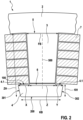
- FIG. 2 shows schematically a section of the stator 1 of the electrical machine 10 according to the exemplary embodiment of the invention. It can be seen in particular that the stator 2 is provided for a stator winding 7, the electrical conductors of which have a rectangular cross section.
- the stator 1 includes a stator yoke 2, which is formed in a ring shape around the stator axis 400.
- a plurality of stator teeth 3 extend from the radial inside of the stator yoke, the stator teeth 3 each resting on the stator yoke 2 at a first end 5 and each extending along a tooth axis 500, for example in the radial direction with respect to the stator axis 400.
- At one of the A tooth head 4 is arranged at the second end 6 of the stator teeth 3 opposite the first end 5. It is provided that the stator yoke 2, the individual stator teeth 3 and the associated tooth heads 4 are formed in one piece on each sheet metal lamella 8.
- the winding 7 is attached to the stator tooth 3.
- the stator tooth 3 terminates at its distal end, that is to say at the second end 6, with the respective tooth head 4.
- the tooth head 4 of the stator teeth 3 each has two tooth head projections
- the tooth head 4 of the stator teeth is each trapezoidal and asymmetrical with respect to the respective tooth axis 500.
- the trapezoidal shape of the tooth head includes a base 100, a base side 200 and a first leg 301 and a second leg 302.
- the base 100 and the base side 200 are oriented parallel, with the base 100 being longer than the base side 200.
- the first leg 301 and the second leg 302 each extend between the base 100 and the base side 200, with the first leg 301 and the second leg 302 assuming different angles to the base 100 in terms of magnitude. In this way, an asymmetry of the tooth head 4 is already achieved.
- the base 100 is arranged at the second end 6 of the stator tooth 3.
- asymmetry is further achieved in that a first tooth tip projection X is different from a second tooth tip projection Y.
- the first tooth tip projection Tooth tip projection Y, wherein the second tooth tip projection Y preferably corresponds to 0.4 times to 0.85 times the first tooth tip projection X.
- the trapezoidal shape of the tooth head 4 ensures that current heat losses of the electrical conductor that rests on the tooth head 4 are reduced due to current displacement in the groove transverse field. At the same time, losses due to magnetic leakage flux between the tooth heads 3 are reduced. Finally, the different first tooth tip projection At the same time Performance is increased with respect to geometries with identical tooth tip projection.
- a tooth tip width KB of the tooth head 4 is advantageously 0.6 times to 0.95 times the dimension of the base 100.
- the dimension of the base 100 is preferably the sum of the first tooth tip projection X, the second tooth tip projection Y and a stator tooth width Z at the second end 6 of the stator tooth 3. In this way, the acoustically effective tangential tooth tip width in particular is minimized. This can improve the acoustic behavior in terms of tonality, sound power level and torque ripple.
- a root width FB of the stator tooth 3 at the first end 5 is 1.15 times to 1.5 times a tooth height ZH.
- the tooth height ZH corresponds to the distance between the first end 5 and the base side 200.
- a tooth head height KH of the tooth head 4 is 0.06 times to 0.18 times the tooth height ZH.
- the stator 1 is optimally designed for a permanently excited synchronous machine.
- the electrical machine 10 as described above is therefore particularly advantageously a synchronous machine. This is particularly designed for use in hybrid vehicles and/or electric vehicles. Due to the design of the tooth head 4, high torque and high power can be achieved for the electric machine 10. In addition, good acoustic properties are achieved, which is reflected in a low noise level of the electrical machine 10. Likewise, the electric machine 10 has a low torque ripple. Losses of the electrical machine 10 are reduced, which is reflected in particular by reduced copper losses due to the current displacement effect. The manufacturing costs and material costs of the electrical machine 10, in particular the stator 1, are low. A leakage flux loss caused by the tooth heads 4 is minimized. In addition, the tooth tip geometry of the tooth heads 4 is favored with regard to slot insulation.
Landscapes
- Engineering & Computer Science (AREA)
- Power Engineering (AREA)
- Iron Core Of Rotating Electric Machines (AREA)
Description
- Die vorliegende Erfindung betrifft einen Stator einer elektrischen Maschine. Außerdem betrifft die Erfindung eine elektrische Maschine umfassend einen derartigen Stator.
- Aus dem Stand der Technik sind unterschiedliche Statoren für elektrische Maschinen bekannt. Dabei weist der Stator üblicherweise eine Vielzahl von Statorzähnen auf, wobei an Enden der Statorzähne Zahnköpfe angeordnet sind.
- Die Zahnköpfe können unterschiedliche Ausprägungen aufweisen. Bspw. offenbaren die in
DE 10 2008 026 756 B4 , dieUS 6,288,471 A , dieUS 6,984,909 A , sowie die inUS 2006/038458 A1 jeweils unterschiedliche Ausgestaltungen von Zahnköpfen. - Aus den Dokumenten
JP2016034192 A WO2018/020631 A1 ,US6864611 B1 ,JP2013223281 A JP2005304166 A JP2016129450 A US2017373550 A1 sind Statoren mit trapezförmigen und/oder asymmetrischen Zahnköpfen bekannt. - Erfindungsgemäß ist vorgesehen, dass der Stator einer elektrischen Maschine trapezförmige Zahnköpfe, die asymmetrisch angeordnet sind, aufweist. Durch die Trapezform werden Stromwärmeverluste in demjenigen elektrischen Leiter einer Wicklung des Stators, der an dem Zahnkopf anliegt, reduziert. Gleichzeitig werden Verluste durch magnetischen Streufluss zwischen den Zahnköpfen reduziert. Durch die Asymmetrie des Zahnkopfs ist außerdem erreicht, dass begünstigte Eigenschaften bezüglich einer Nutisolation mit überlappendem Isolationspapier geschaffen ist, wodurch eine effektive Zahnkopfbreite sinkt und somit der Streufluss verringert wird, während eine Leistung der elektrischen Maschine mit dem Stator vergrößert ist. Außerdem kann eine akustisch wirksame geringe tangentiale Zahnkopfbreite erreicht werden. Dadurch ist das akustische Verhalten, insbesondere bezüglich Tonalität und Schallleistungspegel, optimiert sowie eine Drehmomentwelligkeit verringert.
- Der Stator einer elektrischen Maschine weist ein Statorjoch auf, der sich ringförmig um eine Statorachse erstreckt. Außerdem weist der Stator sich radial vom Statorjoch und entlang einer jeweiligen Zahnachse erstreckende Statorzähne auf, wobei jeder Statorzahn mit einem ersten Ende an dem Statorjoch angeordnet ist. Außerdem ist an einem dem ersten Ende gegenüberliegenden zweiten Ende ein Zahnkopf ausgebildet. Insbesondere entspricht das erste Ende einem proximalen Ende des Statorzahns, wobei das zweite Ende einem distalen Ende des Statorzahns entspricht. Statorzahn, Statorjoch und Zahnkopf sind vorteilhafterweise allesamt aus demselben Material gefertigt, insbesondere einstückig. Weiterhin ist bevorzugt vorgesehen, dass Statorjoch, Statorzähne und Zahnköpfe aus einem magnetisch leitfähigen Material gefertigt sind. Der Zahnkopf weist insbesondere zwei Zahnkopfüberstände auf, die jeweils quer zur Zahnachse gegenüber dem übrigen Statorzahn unter Bildung einer Zahnkopfstufe auskragen. Es ist vorgesehen, dass der Zahnkopf der Statorzähne trapezförmig, insbesondere mit einem trapezförmigen Querschnitt, ausgebildet ist. Dieser Querschnitt liegt insbesondere in einer Ebene senkrecht zur Statorachse. Außerdem ist vorgesehen, dass jeder Zahnkopf bezüglich der jeweiligen Zahnachse asymmetrisch ausgebildet ist. Auf diese Weise lassen sich die zuvor beschriebenen Vorteile erreichen. Eine asymmetrische Anordnung liegt insbesondere dann vor, wenn Zahnkopfüberstände in Tangentialrichtung oder bezüglich der Statorachse in Umfangsrichtung bezüglich der Außenflächen des Statorzahns unterschiedlich sind.
- Die Unteransprüche haben bevorzugte Weiterbildungen der Erfindung zum Inhalt.
- Die beiden Zahnkopfüberstände desselben Zahnkopfes sind bevorzugt unterschiedlich lang ausgebildet. Dabei sind die unterschiedlichen Längen der beiden Zahnkopfüberstände insbesondere in derselben Ebene senkrecht zur Zahnachse, insbesondere an der Stufe des Zahnkopfes, gemessen.
- Es ist vorgesehen, dass die in Trapezform der jeweiligen Zahnköpfe eine der Zahnkopfstufe zugewandte Basis, eine der Zahnkopfstufe abgewandte Grundseite sowie einen ersten Schenkel und einen zweiten Schenkel aufweist.
- Der erste Schenkel und der zweite Schenkel erstrecken sich jeweils zwischen Basis und Grundseite. Die beiden Schenkel nehmen besonders vorteilhaft betragsmäßig unterschiedliche Winkel zu der Basis ein. Außerdem ist vorgesehen, dass die Basis länger ist als die Grundseite. Die Basis und die Grundseite sind parallel zueinander orientiert, wobei der erste Schenkel und der zweite Schenkel bevorzugt nicht parallel zueinander verlaufen. Somit ist eine Trapezform vorhanden. Es ist weiterhin vorgesehen, dass die Basis an dem zweiten Ende des Statorzahns anliegt. Aufgrund einer derartigen Orientierung der Trapezform lassen sich die zuvor beschriebenen Eigenschaften und Vorteile in besonders vorteilhafter Weise erreichen.
- Ein erster Zahnkopfüberstand, der dem Teilbereich der Basis zwischen erstem Schenkel und Statorzahn entspricht, ist größer als ein zweiter Zahnkopfüberstand, der dem Teilbereich der Basis zwischen Statorzahn und zweitem Schenkel entspricht. Auf diese Weise ist die Trapezform asymmetrisch gegenüber dem Statorzahn angeordnet. Eine solche Asymmetrie und unterschiedliche Zahnkopfüberstände haben einen Vorteil hinsichtlich der effektiven Zahnbreite, der aufgrund der unterschiedlichen Zahnkopfüberstände und der daraus resultierenden Asymmetrie verringert ist.
- Der erste Zahnkopfüberstand und/oder der zweite Zahnkopfüberstand entsprechen bevorzugt dem 0,05-Fachen bis 0,4-Fachen einer Statorzahnbreite am zweiten Ende des Statorzahns. Die Statorzahnbreite entspricht somit dem Bereich der Basis, der zwischen dem ersten Zahnkopfüberstand und dem zweiten Zahnkopfüberstand liegt. Durch das beschriebene Verhältnis von erstem Zahnkopfüberstand und/oder zweitem Zahnkopfüberstand zu der Statorzahnbreite lässt sich die zuvor beschriebene Asymmetrie in besonders vorteilhafter Weise erreichen.
- Der zweite Zahnkopfüberstand beträgt dem 0,4-Fachen bis 0,85-Fachen des ersten Zahnkopfüberstands. Dadurch ist eine optimale Asymmetrie der Trapezform relativ zu dem Statorzahn erreicht.
- Eine Zahnkopfbreite des Statorzahns entspricht bevorzugt dem 0,6-Fachen bis 0,95-Fachen einer Abmessung der Basis. Die Abmessung der Basis ist besonders vorteilhaft die Summe aus erstem Zahnkopfüberstand, zweitem Zahnkopfüberstand und Statorzahnbreite am zweiten Ende des Statorzahns. Auf diese Weise ist die Größe des Zahnkopfs optimiert.
- Eine Fußbreite des Statorzahns am ersten Ende entspricht bevorzugt dem 1,15-Fachen bis 1,5-Fachen einer Zahnhöhe. Die Zahnhöhe entspricht dem Abstand zwischen erstem Ende und Grundseite der Trapezform. Somit handelt es sich um die gesamte Höhe von Statorzahn und Zahnkopf, das heißt, die gesamte Höhe desjenigen Elements, das sich von dem Statorjoch ausgehend radial erstreckt.
- Eine Zahnkopfhöhe des Zahnkopfs entspricht vorteilhafterweise dem 0,06-Fachen bis 0,18-Fachen einer Zahnhöhe. Die Zahnhöhe ist dabei dieselbe Zahnhöhe wie zuvor beschrieben. Durch ein derartiges Verhältnis kann wiederum die Größe des Zahnkopfs optimal erreicht werden.
- In einer besonders vorteilhaften Ausgestaltung ist vorgesehen, dass der Stator eine Vielzahl von gestapelten Blechlamellen aufweist. An jeder Blechlamelle sind das Statorjoch, die Statorzähne und die Zahnköpfe einstückig ausgebildet. Somit ist der Stator einfach und kostengünstig herzustellen. Eine Montage erfolgt analog zu bekannten Statoren, die aus einer Vielzahl von Blechlamellen hergestellt sind. Die Blechlamellen sind vorteilhafterweise aus Elektroblech gefertigt.
- Die Erfindung betrifft schließlich eine elektrische Maschine. Die elektrische Maschine weist einen Stator auf, der zuvor beschrieben wurde. Außerdem weist die elektrische Maschine einen Rotor auf, wobei der Stator eine Statorwicklung aufweist, die zu Antreiben des Rotors ausgebildet ist. Die Statorwicklung ist besonders vorteilhaft aus zumindest einem elektrischen Leiter mit rechteckförmigem Querschnitt gebildet. Die spezielle Form und Ausgestaltung der Statorzähne wie zuvor beschrieben, wirkt sich besonders vorteilhaft dann aus, wenn die elektrischen Leiter der Wicklung einen rechteckförmigen Querschnitt aufweisen.
- Nachfolgend werden Ausführungsbeispiele der Erfindung unter Bezugnahme auf die begleitende Zeichnung im Detail beschrieben. In der Zeichnung ist:
- Figur 1
- eine schematische Abbildung einer elektrischen Maschine gemäß einem Ausführungsbeispiel der Erfindung, und
- Figur 2
- eine schematische Abbildung eines Teilbereichs eines Stators der elektrischen Maschine gemäß dem Ausführungsbeispiel der Erfindung.
-
Figur 1 zeigt schematisch eine elektrische Maschine 10 gemäß einem Ausführungsbeispiel der Erfindung. Die elektrische Maschine 10 weist einen Stator 1 sowie eine Rotor 9 auf. Dabei erstreckt sich der Stator 1 um eine Statorachse 400. Der Stator 1 ist dabei bevorzugt aus einer Vielzahl von Blechlamellen 8 gebildet, die zu dem Stator 1 gestapelt sind. Außerdem ist der Stator 1 an einem Gehäuse 11 der elektrischen Maschine 10 aufgenommen. -
Figur 2 zeigt schematisch einen Ausschnitt des Stators 1 der elektrischen Maschine 10 gemäß dem Ausführungsbeispiel der Erfindung. Dabei ist insbesondere ersichtlich, dass der Stator 2 für eine Statorwicklung 7 vorgesehen ist, deren elektrische Leiter einen rechteckigen Querschnitt aufweisen. - Der Stator 1 umfasst ein Statorjoch 2, das ringförmig um die Statorachse 400 ausgebildet ist. Von der radialen Innenseite des Statorjochs erstrecken sich eine Vielzahl von Statorzähnen 3, wobei die Statorzähne 3 jeweils an einem ersten Ende 5 an dem Statorjoch 2 anliegen und sich jeweils entlang einer Zahnachse 500 erstrecken, beispielsweise in radialer Richtung bezüglich der Statorachse 400. An einem dem ersten Ende 5 gegenüberliegendem zweiten Ende 6 der Statorzähne 3 ist jeweils ein Zahnkopf 4 angeordnet. Dabei ist vorgesehen, dass an jeder Blechlamelle 8 das Statorjoch 2, die einzelnen Statorzähne 3 und die zugehörigen Zahnköpfe 4 einstückig ausgebildet sind. An dem Statorzahn 3 ist die Wicklung 7 angebracht. Der Statorzahn 3 schließt an seinem distalen Ende, das heißt an dem zweiten Ende 6, mit dem jeweiligen Zahnkopf 4 ab.
- Der Zahnkopf 4 der Statorzähne 3 weist jeweils zwei Zahnkopfüberstände X, Y auf, die jeweils quer zur Zahnachse 500 gegenüber dem übrigen Statorzahn 3 unter Bildung einer Zahnkopfstufe 4.1 auskragen.
- Erfindungsgemäß ist vorgesehen, dass der Zahnkopf 4 der Statorzähne jeweils trapezförmig und bezüglich der jeweiligen Zahnachse 500 asymmetrisch ausgebildet ist.
- Die Trapezform des Zahnkopfs umfasst eine Basis 100, eine Grundseite 200 sowie einen ersten Schenkel 301 und einen zweiten Schenkel 302. Die Basis 100 und die Grundseite 200 sind parallel orientiert, wobei die Basis 100 länger ist als die Grundseite 200. Der erste Schenkel 301 und der zweite Schenkel 302 erstrecken sich jeweils zwischen Basis 100 und Grundseite 200, wobei der erste Schenkel 301 und der zweite Schenkel 302 zur Basis 100 betragsmäßig unterschiedliche Winkel einnehmen. Auf diese Weise ist bereits eine Asymmetrie des Zahnkopfs 4 erreicht.
- Die Basis 100 ist an dem zweiten Ende 6 des Statorzahns 3 angeordnet. Außerdem wird eine Asymmetrie weiterhin dadurch erreicht, dass ein erster Zahnkopfüberstand X unterschiedlich von einem zweiten Zahnkopfüberstand Y ist. Der erste Zahnkopfüberstand X entspricht dem Teilbereich der Basis 100 zwischen erstem Schenkel 301 und Statorzahn 3. Der zweite Zahnkopfüberstand Y entspricht dem Teilbereich der Basis 100 zwischen Statorzahn 3 und zweitem Schenkel 302. Es ist vorgesehen, dass der erste Zahnkopfüberstand X größer ist als der zweite Zahnkopfüberstand Y, wobei der zweite Zahnkopfüberstand Y bevorzugt dem 0,4-Fachen bis 0,85-Fachen des ersten Zahnkopfüberstands X entspricht.
- Durch die Trapezform des Zahnkopfs 4 ist erreicht, dass Stromwärmeverluste desjenigen elektrischen Leiters, der an dem Zahnkopf 4 anliegt, bedingt durch Stromverdrängung im Nutquerfeld reduziert ist. Gleichzeitig werden Verluste durch magnetischen Streufluss zwischen den Zahnköpfen 3 reduziert. Schließlich ist durch den unterschiedlichen ersten Zahnkopfüberstand X und zweiten Zahnkopfüberstand Y erreicht, dass begünstigende Eigenschaften bezüglich der Nutisolation mit überlappendem Isolationspapier geschaffen werden, wodurch die effektive Zahnkopfbreite sinkt und somit der Streufluss reduziert ist. Gleichzeitig ist eine Leistung bezüglich Geometrien mit identischem Zahnkopfüberstand erhöht.
- Eine Zahnkopfbreite KB des Zahnkopfs 4 beträgt vorteilhafterweise das 0,6-Fache bis 0,95-Fache der Abmessung der Basis 100. Die Abmessung der Basis 100 ist bevorzugt die Summe aus erstem Zahnkopfüberstand X, zweitem Zahnkopfüberstand Y und einer Statorzahnbreite Z am zweiten Ende 6 des Statorzahns 3. Auf diese Weise ist insbesondere die akustisch wirksame tangentiale Zahnkopfbreite minimiert. Dadurch lässt sich das akustische Verhalten bezüglich Tonalität, Schallleistungspegel sowie Drehmomentwelligkeit begünstigen.
- Besonders vorteilhaft ist außerdem vorgesehen, dass eine Fußbreite FB des Statorzahns 3 am ersten Ende 5 das 1,15-Fache bis 1,5-Fache einer Zahnhöhe ZH beträgt. Die Zahnhöhe ZH entspricht dem Abstand zwischen erstem Ende 5 und Grundseite 200. Außerdem ist vorgesehen, dass eine Zahnkopfhöhe KH des Zahnkopfs 4 das 0,06-Fache bis 0,18-Fache der Zahnhöhe ZH beträgt.
- Durch die Ausgestaltung des Zahnkopfs 4 mit dem trapezförmigen Querschnitt sowie insbesondere in der Asymmetrie, ist der Stator 1 optimal für eine permanent erregte Synchronmaschine ausgelegt. Die elektrische Maschine 10 wie zuvor beschrieben ist somit besonders vorteilhaft eine Synchronmaschine. Diese ist insbesondere ausgebildet für den Einsatz in Hybridfahrzeugen und/oder Elektrofahrzeugen. Aufgrund der Ausgestaltung des Zahnkopfs 4 lässt sich für die elektrische Maschine 10 ein hohes Drehmoment sowie eine hohe Leistung erreichen. Außerdem werden gute akustische Eigenschaften erreicht, was sich in einem niedrigen Geräuschpegel der elektrischen Maschine 10 wiederspiegelt. Ebenso weist die elektrische Maschine 10 eine geringe Drehmomentwelligkeit auf. Verluste der elektrischen Maschine 10 sind dabei reduziert, was sich insbesondere durch reduzierte Kupferverluste durch Stromverdrängungseffekt wiederspiegelt. Die Herstellungskosten sowie Materialkosten der elektrischen Maschine 10, insbesondere des Stators 1, sind gering. Ein durch die Zahnköpfe 4 bedingter Streuflussverlust ist minimiert. Außerdem ist die Zahnkopfgeometrie der Zahnköpfe 4 bezüglich Nutisolation begünstigt.
Claims (8)
- Stator (1) einer elektrischen Maschine (10), der ein sich ringförmig um eine Statorachse (400) erstreckendes Statorjoch (2) und in radialer Richtung bezüglich der Statorachse (400) vom Statorjoch (2) abstehende, jeweils sich entlang einer Zahnachse (500) erstreckende Statorzähne (3) aufweist, wobei jeder Statorzahn (3) mit einem ersten Ende (5) an dem Statorjoch (2) angeordnet ist und an einem dem ersten Ende (5) gegenüberliegenden zweiten Ende (6) ein Zahnkopf (4) ausgebildet ist, der jeweils zwei Zahnkopfüberstände (X, Y) aufweist, die jeweils quer zur Zahnachse (500) gegenüber dem übrigen Statorzahn (3) unter Bildung einer Zahnkopfstufe (4.1) auskragen, wobei der Zahnkopf (4) der Statorzähne (3) jeweils trapezförmig und bezüglich der jeweiligen Zahnachse (500) asymmetrisch ausgebildet ist, wobei die Trapezform des Zahnkopfs (4) eine der Zahnkopfstufe (4.1) zugewandte Basis (100), eine der Zahnkopfstufe (4.1) abgewandte Grundseite (200), sowie einen ersten Schenkel (301) und einen zweiten Schenkel (302) aufweist, wobei sich der erste Schenkel (301) und der zweite Schenkel (302) jeweils zwischen Basis (100) und Grundseite (200) erstrecken, und insbesondere betragsmäßig unterschiedliche Winkel zu der Basis (100) einnehmen, wobei die Basis (100) länger ist als die Grundseite (200), wobei die Basis (100) und die Grundseite (200) parallel zueinander verlaufen, wobei der erste Schenkel (301) und der zweite Schenkel (302) bevorzugt nichtparallel verlaufen, und wobei die Basis (100) an dem zweiten Ende (6) des Statorzahns (3) anliegt, wobei ein erster Zahnkopfüberstand (X), der dem Teilbereich der Basis (100) zwischen erstem Schenkel (301) und Statorzahn (3) entspricht, größer ist als ein zweiter Zahnkopfüberstand (Y), der dem Teilbereich der Basis (100) zwischen Statorzahn (3) und zweitem Schenkel (302) entspricht, und dass der zweite Zahnkopfüberstand (Y) das 0,4-Fache bis 0,85-Fache des ersten Zahnkopfüberstands (X) beträgt.
- Stator (1) nach Anspruch 1, dadurch gekennzeichnet, dass die beiden Zahnkopfüberstände (X, Y) desselben Zahnkopfes (4) unterschiedlich lang ausgebildet sind, wobei die unterschiedlichen Längen der beiden Zahnkopfüberstände (X,Y) in derselben Ebene senkrecht zur Zahnachse (500), insbesondere an der Zahnkopfstufe (4.1), gemessen sind.
- Stator (1) nach Anspruch 1, dadurch gekennzeichnet, dass der erste Zahnkopfüberstand (X) und/oder der zweite Zahnkopfüberstand (Y) dem 0,05-Fachen bis 0,4-Fachen einer Statorzahnbreite (Z) am zweiten Ende (6) des Statorzahns (3) entspricht.
- Stator (1) nach einem der Ansprüche 1 bis 3, dadurch gekennzeichnet, dass eine Zahnkopfbreite (KB) des Zahnkopfs (4) das 0,6-Fache bis 0,95-Fache der Abmessung der Basis (100) beträgt, wobei die Abmessung der Basis (100) bevorzugt der Summe aus erstem Zahnkopfüberstand (X), zweitem Zahnkopfüberstand (Y) und Statorzahnbreite (Z) am zweiten Ende (6) des Statorzahns (3) entspricht.
- Stator (1) nach einem der Ansprüche 1 bis 4, dadurch gekennzeichnet, dass eine Fußbreite (FB) des Statorzahns (3) am ersten Ende (5) das 1,15-Fache bis 1,5-Fache einer Zahnhöhe (ZH) beträgt, wobei die Zahnhöhe (ZH) dem Abstand zwischen erstem Ende (5) und Grundseite (200) entspricht.
- Stator (1) nach einem der Ansprüche 1 bis 5, dadurch gekennzeichnet, dass eine Zahnkopfhöhe (KH) des Zahnkopfs (4) das 0,06-Fache bis 0,18-Fache einer Zahnhöhe (ZH) beträgt, wobei die Zahnhöhe (ZH) dem Abstand zwischen erstem Ende (5) und Grundseite (200) entspricht.
- Stator (1) nach einem der vorhergehenden Ansprüche, gekennzeichnet durch eine Vielzahl von gestapelten Blechlamellen (8), wobei an jeder Blechlamelle (8) das Statorjoch (2), die Statorzähne (3) und die Zahnköpfe (4) einstückig ausgebildet sind.
- Elektrische Maschine (10) aufweisend einen Stator (1) nach einem der vorhergehenden Ansprüche und einen Rotor (9), wobei der Stator (1) eine Statorwicklung (7) aufweist, die zum Antreiben des Rotors (9) ausgebildet ist, und wobei die Statorwicklung (7) bevorzugt aus zumindest einem elektrischen Leiter mit rechteckförmigen Querschnitt gebildet ist.
Applications Claiming Priority (2)
| Application Number | Priority Date | Filing Date | Title |
|---|---|---|---|
| DE102019207471.5A DE102019207471A1 (de) | 2019-05-22 | 2019-05-22 | Stator einer elektrischen Maschine |
| PCT/EP2020/061890 WO2020233959A1 (de) | 2019-05-22 | 2020-04-29 | Stator einer elektrischen maschine |
Publications (2)
| Publication Number | Publication Date |
|---|---|
| EP3973613A1 EP3973613A1 (de) | 2022-03-30 |
| EP3973613B1 true EP3973613B1 (de) | 2024-01-24 |
Family
ID=70480282
Family Applications (1)
| Application Number | Title | Priority Date | Filing Date |
|---|---|---|---|
| EP20723098.8A Active EP3973613B1 (de) | 2019-05-22 | 2020-04-29 | Stator einer elektrischen maschine |
Country Status (3)
| Country | Link |
|---|---|
| EP (1) | EP3973613B1 (de) |
| DE (1) | DE102019207471A1 (de) |
| WO (1) | WO2020233959A1 (de) |
Family Cites Families (11)
| Publication number | Priority date | Publication date | Assignee | Title |
|---|---|---|---|---|
| DE19729034A1 (de) * | 1997-07-08 | 1999-01-21 | Aloys Wobben | Synchrongenerator zum Einsatz bei Windenergieanlagen sowie Windenergieanlage |
| JP3242635B2 (ja) | 1999-01-28 | 2001-12-25 | 三菱電機株式会社 | 交流発電機 |
| AU2003236179A1 (en) | 2002-03-29 | 2003-10-13 | Matsushita Electric Industrial Co., Ltd. | Motor |
| JP2005304166A (ja) * | 2004-04-09 | 2005-10-27 | Toyota Industries Corp | 回転電機のステータコア |
| JP3672919B1 (ja) | 2004-08-17 | 2005-07-20 | 山洋電気株式会社 | 永久磁石型回転モータ |
| US7969058B2 (en) | 2007-06-07 | 2011-06-28 | GM Global Technology Operations LLC | Permanent magnet motor with stator having asymmetric slots for reducing torque ripple |
| JP2013223281A (ja) * | 2012-04-13 | 2013-10-28 | Jtekt Corp | 電動モータ |
| JP2016034192A (ja) * | 2014-07-31 | 2016-03-10 | 株式会社東芝 | 固定子および回転電機 |
| JP2016129450A (ja) * | 2015-01-09 | 2016-07-14 | 株式会社東芝 | 回転電機 |
| JP6638135B2 (ja) * | 2016-06-22 | 2020-01-29 | 本田技研工業株式会社 | 電動機 |
| WO2018020631A1 (ja) * | 2016-07-28 | 2018-02-01 | 三菱電機株式会社 | 電動機、送風機、及び空気調和機 |
-
2019
- 2019-05-22 DE DE102019207471.5A patent/DE102019207471A1/de active Pending
-
2020
- 2020-04-29 WO PCT/EP2020/061890 patent/WO2020233959A1/de not_active Ceased
- 2020-04-29 EP EP20723098.8A patent/EP3973613B1/de active Active
Also Published As
| Publication number | Publication date |
|---|---|
| WO2020233959A1 (de) | 2020-11-26 |
| EP3973613A1 (de) | 2022-03-30 |
| DE102019207471A1 (de) | 2020-11-26 |
Similar Documents
| Publication | Publication Date | Title |
|---|---|---|
| DE112013006383B4 (de) | Drehende elektrische Maschine und Verfahren zum Herstellen eines Ankers, der in der drehenden elektrischen Maschine verwendet wird | |
| EP1000458A1 (de) | Elektrische maschine mit weichmagnetischen zähnen und verfahren zu ihrer herstellung | |
| DE112004001908T5 (de) | Anker einer sich drehenden elektrischen Maschine und deren Herstellverfahren | |
| DE10297146T5 (de) | Stator für eine rotierende elektrische Maschine | |
| WO2011026795A1 (de) | Stator mit separat gefertigten zahnköpfen | |
| DE102012100158A1 (de) | Stator für drehende elektrische Maschinen und Verfahren zum Herstellen desselben | |
| DE112017002986T5 (de) | Permanentmagnet-synchronmaschine und verfahren zum herstellen eines permanentmagnet-synchronmaschinenstators | |
| DE102012100332A1 (de) | Stator für eine rotierende elektrische Maschine und Verfahren zu seiner Herstellung | |
| DE112019003786T5 (de) | Stator und sich drehende Elektromaschine | |
| WO2012016746A2 (de) | Wicklungszahn und komponente für eine elektrische maschine zur reduzierung von wirbelströmen | |
| EP3216113B1 (de) | Rotor oder stator mit gestecktem flachem wickelkopf | |
| DE112016004389T5 (de) | Rotierende elektrische maschine und herstellungsverfahren für eine rotierende elektrische maschine | |
| DE102018221570A1 (de) | Halteelement eines Rotors eines Elektromotors zum Halten von Wicklungen | |
| DE102016211833A1 (de) | Wicklungsträger | |
| DE60320165T2 (de) | Drehende elektrische Maschine | |
| DE3320805C2 (de) | ||
| EP3460957A1 (de) | Stabwicklung für einen stator einer elektrischen rotierenden maschine | |
| WO2018115074A1 (de) | Elektromotor mit niedrigem nutrastmoment | |
| EP3973613A1 (de) | Stator einer elektrischen maschine | |
| DE2117049B2 (de) | Gleichstrommotor mit mindestens vier Erregerpolen und mit einer geraden Anzahl von konzentrierten Ankerspulen | |
| DE102013226149A1 (de) | Maschinenkomponente für eine elektrische Maschine und Verfahren zur Herstellung einer Maschinenkomponente | |
| DE102019122239A1 (de) | Stator | |
| DE102020117464A1 (de) | Stator für eine elektrische Maschine, elektrische Maschine, Kraftfahrzeug, Verfahren zur Herstellung eines Stators | |
| WO2012079892A2 (de) | Maschinenkomponente für eine elektrische maschine | |
| DE102020113725A1 (de) | Elektrische axialflussmaschine und verfahren des zusammenbaus derselben |
Legal Events
| Date | Code | Title | Description |
|---|---|---|---|
| STAA | Information on the status of an ep patent application or granted ep patent |
Free format text: STATUS: UNKNOWN |
|
| STAA | Information on the status of an ep patent application or granted ep patent |
Free format text: STATUS: THE INTERNATIONAL PUBLICATION HAS BEEN MADE |
|
| PUAI | Public reference made under article 153(3) epc to a published international application that has entered the european phase |
Free format text: ORIGINAL CODE: 0009012 |
|
| STAA | Information on the status of an ep patent application or granted ep patent |
Free format text: STATUS: REQUEST FOR EXAMINATION WAS MADE |
|
| 17P | Request for examination filed |
Effective date: 20211222 |
|
| AK | Designated contracting states |
Kind code of ref document: A1 Designated state(s): AL AT BE BG CH CY CZ DE DK EE ES FI FR GB GR HR HU IE IS IT LI LT LU LV MC MK MT NL NO PL PT RO RS SE SI SK SM TR |
|
| DAV | Request for validation of the european patent (deleted) | ||
| DAX | Request for extension of the european patent (deleted) | ||
| REG | Reference to a national code |
Ref country code: DE Ref legal event code: R079 Free format text: PREVIOUS MAIN CLASS: H02K0001120000 Ref country code: DE Ref legal event code: R079 Ref document number: 502020006838 Country of ref document: DE Free format text: PREVIOUS MAIN CLASS: H02K0001120000 Ipc: H02K0001140000 |
|
| GRAP | Despatch of communication of intention to grant a patent |
Free format text: ORIGINAL CODE: EPIDOSNIGR1 |
|
| STAA | Information on the status of an ep patent application or granted ep patent |
Free format text: STATUS: GRANT OF PATENT IS INTENDED |
|
| RIC1 | Information provided on ipc code assigned before grant |
Ipc: H02K 1/14 20060101AFI20231002BHEP |
|
| INTG | Intention to grant announced |
Effective date: 20231106 |
|
| GRAS | Grant fee paid |
Free format text: ORIGINAL CODE: EPIDOSNIGR3 |
|
| GRAA | (expected) grant |
Free format text: ORIGINAL CODE: 0009210 |
|
| STAA | Information on the status of an ep patent application or granted ep patent |
Free format text: STATUS: THE PATENT HAS BEEN GRANTED |
|
| AK | Designated contracting states |
Kind code of ref document: B1 Designated state(s): AL AT BE BG CH CY CZ DE DK EE ES FI FR GB GR HR HU IE IS IT LI LT LU LV MC MK MT NL NO PL PT RO RS SE SI SK SM TR |
|
| REG | Reference to a national code |
Ref country code: GB Ref legal event code: FG4D Free format text: NOT ENGLISH |
|
| REG | Reference to a national code |
Ref country code: CH Ref legal event code: EP |
|
| REG | Reference to a national code |
Ref country code: IE Ref legal event code: FG4D Free format text: LANGUAGE OF EP DOCUMENT: GERMAN |
|
| REG | Reference to a national code |
Ref country code: DE Ref legal event code: R096 Ref document number: 502020006838 Country of ref document: DE |
|
| REG | Reference to a national code |
Ref country code: LT Ref legal event code: MG9D |
|
| REG | Reference to a national code |
Ref country code: NL Ref legal event code: MP Effective date: 20240124 |
|
| PG25 | Lapsed in a contracting state [announced via postgrant information from national office to epo] |
Ref country code: NL Free format text: LAPSE BECAUSE OF FAILURE TO SUBMIT A TRANSLATION OF THE DESCRIPTION OR TO PAY THE FEE WITHIN THE PRESCRIBED TIME-LIMIT Effective date: 20240124 |
|
| PG25 | Lapsed in a contracting state [announced via postgrant information from national office to epo] |
Ref country code: NL Free format text: LAPSE BECAUSE OF FAILURE TO SUBMIT A TRANSLATION OF THE DESCRIPTION OR TO PAY THE FEE WITHIN THE PRESCRIBED TIME-LIMIT Effective date: 20240124 |
|
| PG25 | Lapsed in a contracting state [announced via postgrant information from national office to epo] |
Ref country code: IS Free format text: LAPSE BECAUSE OF FAILURE TO SUBMIT A TRANSLATION OF THE DESCRIPTION OR TO PAY THE FEE WITHIN THE PRESCRIBED TIME-LIMIT Effective date: 20240524 |
|
| PG25 | Lapsed in a contracting state [announced via postgrant information from national office to epo] |
Ref country code: LT Free format text: LAPSE BECAUSE OF FAILURE TO SUBMIT A TRANSLATION OF THE DESCRIPTION OR TO PAY THE FEE WITHIN THE PRESCRIBED TIME-LIMIT Effective date: 20240124 |
|
| PG25 | Lapsed in a contracting state [announced via postgrant information from national office to epo] |
Ref country code: GR Free format text: LAPSE BECAUSE OF FAILURE TO SUBMIT A TRANSLATION OF THE DESCRIPTION OR TO PAY THE FEE WITHIN THE PRESCRIBED TIME-LIMIT Effective date: 20240425 |
|
| PG25 | Lapsed in a contracting state [announced via postgrant information from national office to epo] |
Ref country code: RS Free format text: LAPSE BECAUSE OF FAILURE TO SUBMIT A TRANSLATION OF THE DESCRIPTION OR TO PAY THE FEE WITHIN THE PRESCRIBED TIME-LIMIT Effective date: 20240424 Ref country code: HR Free format text: LAPSE BECAUSE OF FAILURE TO SUBMIT A TRANSLATION OF THE DESCRIPTION OR TO PAY THE FEE WITHIN THE PRESCRIBED TIME-LIMIT Effective date: 20240124 |
|
| PG25 | Lapsed in a contracting state [announced via postgrant information from national office to epo] |
Ref country code: ES Free format text: LAPSE BECAUSE OF FAILURE TO SUBMIT A TRANSLATION OF THE DESCRIPTION OR TO PAY THE FEE WITHIN THE PRESCRIBED TIME-LIMIT Effective date: 20240124 |
|
| PG25 | Lapsed in a contracting state [announced via postgrant information from national office to epo] |
Ref country code: RS Free format text: LAPSE BECAUSE OF FAILURE TO SUBMIT A TRANSLATION OF THE DESCRIPTION OR TO PAY THE FEE WITHIN THE PRESCRIBED TIME-LIMIT Effective date: 20240424 Ref country code: NO Free format text: LAPSE BECAUSE OF FAILURE TO SUBMIT A TRANSLATION OF THE DESCRIPTION OR TO PAY THE FEE WITHIN THE PRESCRIBED TIME-LIMIT Effective date: 20240424 Ref country code: LT Free format text: LAPSE BECAUSE OF FAILURE TO SUBMIT A TRANSLATION OF THE DESCRIPTION OR TO PAY THE FEE WITHIN THE PRESCRIBED TIME-LIMIT Effective date: 20240124 Ref country code: IS Free format text: LAPSE BECAUSE OF FAILURE TO SUBMIT A TRANSLATION OF THE DESCRIPTION OR TO PAY THE FEE WITHIN THE PRESCRIBED TIME-LIMIT Effective date: 20240524 Ref country code: HR Free format text: LAPSE BECAUSE OF FAILURE TO SUBMIT A TRANSLATION OF THE DESCRIPTION OR TO PAY THE FEE WITHIN THE PRESCRIBED TIME-LIMIT Effective date: 20240124 Ref country code: GR Free format text: LAPSE BECAUSE OF FAILURE TO SUBMIT A TRANSLATION OF THE DESCRIPTION OR TO PAY THE FEE WITHIN THE PRESCRIBED TIME-LIMIT Effective date: 20240425 Ref country code: FI Free format text: LAPSE BECAUSE OF FAILURE TO SUBMIT A TRANSLATION OF THE DESCRIPTION OR TO PAY THE FEE WITHIN THE PRESCRIBED TIME-LIMIT Effective date: 20240124 Ref country code: ES Free format text: LAPSE BECAUSE OF FAILURE TO SUBMIT A TRANSLATION OF THE DESCRIPTION OR TO PAY THE FEE WITHIN THE PRESCRIBED TIME-LIMIT Effective date: 20240124 Ref country code: BG Free format text: LAPSE BECAUSE OF FAILURE TO SUBMIT A TRANSLATION OF THE DESCRIPTION OR TO PAY THE FEE WITHIN THE PRESCRIBED TIME-LIMIT Effective date: 20240124 |
|
| PG25 | Lapsed in a contracting state [announced via postgrant information from national office to epo] |
Ref country code: PL Free format text: LAPSE BECAUSE OF FAILURE TO SUBMIT A TRANSLATION OF THE DESCRIPTION OR TO PAY THE FEE WITHIN THE PRESCRIBED TIME-LIMIT Effective date: 20240124 Ref country code: PT Free format text: LAPSE BECAUSE OF FAILURE TO SUBMIT A TRANSLATION OF THE DESCRIPTION OR TO PAY THE FEE WITHIN THE PRESCRIBED TIME-LIMIT Effective date: 20240524 |
|
| PG25 | Lapsed in a contracting state [announced via postgrant information from national office to epo] |
Ref country code: SE Free format text: LAPSE BECAUSE OF FAILURE TO SUBMIT A TRANSLATION OF THE DESCRIPTION OR TO PAY THE FEE WITHIN THE PRESCRIBED TIME-LIMIT Effective date: 20240124 Ref country code: PT Free format text: LAPSE BECAUSE OF FAILURE TO SUBMIT A TRANSLATION OF THE DESCRIPTION OR TO PAY THE FEE WITHIN THE PRESCRIBED TIME-LIMIT Effective date: 20240524 Ref country code: PL Free format text: LAPSE BECAUSE OF FAILURE TO SUBMIT A TRANSLATION OF THE DESCRIPTION OR TO PAY THE FEE WITHIN THE PRESCRIBED TIME-LIMIT Effective date: 20240124 Ref country code: LV Free format text: LAPSE BECAUSE OF FAILURE TO SUBMIT A TRANSLATION OF THE DESCRIPTION OR TO PAY THE FEE WITHIN THE PRESCRIBED TIME-LIMIT Effective date: 20240124 |
|
| PG25 | Lapsed in a contracting state [announced via postgrant information from national office to epo] |
Ref country code: DK Free format text: LAPSE BECAUSE OF FAILURE TO SUBMIT A TRANSLATION OF THE DESCRIPTION OR TO PAY THE FEE WITHIN THE PRESCRIBED TIME-LIMIT Effective date: 20240124 |
|
| PG25 | Lapsed in a contracting state [announced via postgrant information from national office to epo] |
Ref country code: SM Free format text: LAPSE BECAUSE OF FAILURE TO SUBMIT A TRANSLATION OF THE DESCRIPTION OR TO PAY THE FEE WITHIN THE PRESCRIBED TIME-LIMIT Effective date: 20240124 |
|
| PG25 | Lapsed in a contracting state [announced via postgrant information from national office to epo] |
Ref country code: CZ Free format text: LAPSE BECAUSE OF FAILURE TO SUBMIT A TRANSLATION OF THE DESCRIPTION OR TO PAY THE FEE WITHIN THE PRESCRIBED TIME-LIMIT Effective date: 20240124 Ref country code: EE Free format text: LAPSE BECAUSE OF FAILURE TO SUBMIT A TRANSLATION OF THE DESCRIPTION OR TO PAY THE FEE WITHIN THE PRESCRIBED TIME-LIMIT Effective date: 20240124 |
|
| REG | Reference to a national code |
Ref country code: DE Ref legal event code: R097 Ref document number: 502020006838 Country of ref document: DE |
|
| PG25 | Lapsed in a contracting state [announced via postgrant information from national office to epo] |
Ref country code: SK Free format text: LAPSE BECAUSE OF FAILURE TO SUBMIT A TRANSLATION OF THE DESCRIPTION OR TO PAY THE FEE WITHIN THE PRESCRIBED TIME-LIMIT Effective date: 20240124 |
|
| PG25 | Lapsed in a contracting state [announced via postgrant information from national office to epo] |
Ref country code: SM Free format text: LAPSE BECAUSE OF FAILURE TO SUBMIT A TRANSLATION OF THE DESCRIPTION OR TO PAY THE FEE WITHIN THE PRESCRIBED TIME-LIMIT Effective date: 20240124 Ref country code: SK Free format text: LAPSE BECAUSE OF FAILURE TO SUBMIT A TRANSLATION OF THE DESCRIPTION OR TO PAY THE FEE WITHIN THE PRESCRIBED TIME-LIMIT Effective date: 20240124 Ref country code: EE Free format text: LAPSE BECAUSE OF FAILURE TO SUBMIT A TRANSLATION OF THE DESCRIPTION OR TO PAY THE FEE WITHIN THE PRESCRIBED TIME-LIMIT Effective date: 20240124 Ref country code: DK Free format text: LAPSE BECAUSE OF FAILURE TO SUBMIT A TRANSLATION OF THE DESCRIPTION OR TO PAY THE FEE WITHIN THE PRESCRIBED TIME-LIMIT Effective date: 20240124 Ref country code: CZ Free format text: LAPSE BECAUSE OF FAILURE TO SUBMIT A TRANSLATION OF THE DESCRIPTION OR TO PAY THE FEE WITHIN THE PRESCRIBED TIME-LIMIT Effective date: 20240124 |
|
| PG25 | Lapsed in a contracting state [announced via postgrant information from national office to epo] |
Ref country code: MC Free format text: LAPSE BECAUSE OF FAILURE TO SUBMIT A TRANSLATION OF THE DESCRIPTION OR TO PAY THE FEE WITHIN THE PRESCRIBED TIME-LIMIT Effective date: 20240124 |
|
| PG25 | Lapsed in a contracting state [announced via postgrant information from national office to epo] |
Ref country code: MC Free format text: LAPSE BECAUSE OF FAILURE TO SUBMIT A TRANSLATION OF THE DESCRIPTION OR TO PAY THE FEE WITHIN THE PRESCRIBED TIME-LIMIT Effective date: 20240124 |
|
| PLBE | No opposition filed within time limit |
Free format text: ORIGINAL CODE: 0009261 |
|
| REG | Reference to a national code |
Ref country code: CH Ref legal event code: PL |
|
| STAA | Information on the status of an ep patent application or granted ep patent |
Free format text: STATUS: NO OPPOSITION FILED WITHIN TIME LIMIT |
|
| PG25 | Lapsed in a contracting state [announced via postgrant information from national office to epo] |
Ref country code: LU Free format text: LAPSE BECAUSE OF NON-PAYMENT OF DUE FEES Effective date: 20240429 |
|
| REG | Reference to a national code |
Ref country code: BE Ref legal event code: MM Effective date: 20240430 |
|
| PG25 | Lapsed in a contracting state [announced via postgrant information from national office to epo] |
Ref country code: LU Free format text: LAPSE BECAUSE OF NON-PAYMENT OF DUE FEES Effective date: 20240429 |
|
| 26N | No opposition filed |
Effective date: 20241025 |
|
| PG25 | Lapsed in a contracting state [announced via postgrant information from national office to epo] |
Ref country code: BE Free format text: LAPSE BECAUSE OF NON-PAYMENT OF DUE FEES Effective date: 20240430 |
|
| PG25 | Lapsed in a contracting state [announced via postgrant information from national office to epo] |
Ref country code: BE Free format text: LAPSE BECAUSE OF NON-PAYMENT OF DUE FEES Effective date: 20240430 Ref country code: CH Free format text: LAPSE BECAUSE OF NON-PAYMENT OF DUE FEES Effective date: 20240430 |
|
| PG25 | Lapsed in a contracting state [announced via postgrant information from national office to epo] |
Ref country code: IE Free format text: LAPSE BECAUSE OF NON-PAYMENT OF DUE FEES Effective date: 20240429 |
|
| PG25 | Lapsed in a contracting state [announced via postgrant information from national office to epo] |
Ref country code: SI Free format text: LAPSE BECAUSE OF FAILURE TO SUBMIT A TRANSLATION OF THE DESCRIPTION OR TO PAY THE FEE WITHIN THE PRESCRIBED TIME-LIMIT Effective date: 20240124 |
|
| PGFP | Annual fee paid to national office [announced via postgrant information from national office to epo] |
Ref country code: DE Payment date: 20250624 Year of fee payment: 6 |
|
| PGFP | Annual fee paid to national office [announced via postgrant information from national office to epo] |
Ref country code: IT Payment date: 20250430 Year of fee payment: 6 |
|
| PGFP | Annual fee paid to national office [announced via postgrant information from national office to epo] |
Ref country code: FR Payment date: 20250422 Year of fee payment: 6 |
|
| PGFP | Annual fee paid to national office [announced via postgrant information from national office to epo] |
Ref country code: AT Payment date: 20250721 Year of fee payment: 5 |
|
| PG25 | Lapsed in a contracting state [announced via postgrant information from national office to epo] |
Ref country code: CY Free format text: LAPSE BECAUSE OF FAILURE TO SUBMIT A TRANSLATION OF THE DESCRIPTION OR TO PAY THE FEE WITHIN THE PRESCRIBED TIME-LIMIT; INVALID AB INITIO Effective date: 20200429 |
|
| PG25 | Lapsed in a contracting state [announced via postgrant information from national office to epo] |
Ref country code: RO Free format text: LAPSE BECAUSE OF FAILURE TO SUBMIT A TRANSLATION OF THE DESCRIPTION OR TO PAY THE FEE WITHIN THE PRESCRIBED TIME-LIMIT Effective date: 20240124 |
|
| PG25 | Lapsed in a contracting state [announced via postgrant information from national office to epo] |
Ref country code: HU Free format text: LAPSE BECAUSE OF FAILURE TO SUBMIT A TRANSLATION OF THE DESCRIPTION OR TO PAY THE FEE WITHIN THE PRESCRIBED TIME-LIMIT; INVALID AB INITIO Effective date: 20200429 |
|
| PGFP | Annual fee paid to national office [announced via postgrant information from national office to epo] |
Ref country code: GB Payment date: 20260324 Year of fee payment: 7 |