EP3973034B1 - Verfahren zur erhöhung der leuchtstoffrobustheit und -dispergierbarkeit und resultierende leuchtstoffe - Google Patents
Verfahren zur erhöhung der leuchtstoffrobustheit und -dispergierbarkeit und resultierende leuchtstoffe Download PDFInfo
- Publication number
- EP3973034B1 EP3973034B1 EP20809356.7A EP20809356A EP3973034B1 EP 3973034 B1 EP3973034 B1 EP 3973034B1 EP 20809356 A EP20809356 A EP 20809356A EP 3973034 B1 EP3973034 B1 EP 3973034B1
- Authority
- EP
- European Patent Office
- Prior art keywords
- phosphor
- fluoride
- composition
- combination
- formula
- Prior art date
- Legal status (The legal status is an assumption and is not a legal conclusion. Google has not performed a legal analysis and makes no representation as to the accuracy of the status listed.)
- Active
Links
Images


Classifications
-
- C—CHEMISTRY; METALLURGY
- C09—DYES; PAINTS; POLISHES; NATURAL RESINS; ADHESIVES; COMPOSITIONS NOT OTHERWISE PROVIDED FOR; APPLICATIONS OF MATERIALS NOT OTHERWISE PROVIDED FOR
- C09K—MATERIALS FOR MISCELLANEOUS APPLICATIONS, NOT PROVIDED FOR ELSEWHERE
- C09K11/00—Luminescent, e.g. electroluminescent, chemiluminescent materials
- C09K11/08—Luminescent, e.g. electroluminescent, chemiluminescent materials containing inorganic luminescent materials
- C09K11/67—Luminescent, e.g. electroluminescent, chemiluminescent materials containing inorganic luminescent materials containing refractory metals
- C09K11/674—Halogenides
- C09K11/675—Halogenides with alkali or alkaline earth metals
-
- C—CHEMISTRY; METALLURGY
- C09—DYES; PAINTS; POLISHES; NATURAL RESINS; ADHESIVES; COMPOSITIONS NOT OTHERWISE PROVIDED FOR; APPLICATIONS OF MATERIALS NOT OTHERWISE PROVIDED FOR
- C09K—MATERIALS FOR MISCELLANEOUS APPLICATIONS, NOT PROVIDED FOR ELSEWHERE
- C09K11/00—Luminescent, e.g. electroluminescent, chemiluminescent materials
- C09K11/02—Use of particular materials as binders, particle coatings or suspension media therefor
- C09K11/025—Use of particular materials as binders, particle coatings or suspension media therefor non-luminescent particle coatings or suspension media
-
- C—CHEMISTRY; METALLURGY
- C09—DYES; PAINTS; POLISHES; NATURAL RESINS; ADHESIVES; COMPOSITIONS NOT OTHERWISE PROVIDED FOR; APPLICATIONS OF MATERIALS NOT OTHERWISE PROVIDED FOR
- C09K—MATERIALS FOR MISCELLANEOUS APPLICATIONS, NOT PROVIDED FOR ELSEWHERE
- C09K11/00—Luminescent, e.g. electroluminescent, chemiluminescent materials
- C09K11/08—Luminescent, e.g. electroluminescent, chemiluminescent materials containing inorganic luminescent materials
- C09K11/61—Luminescent, e.g. electroluminescent, chemiluminescent materials containing inorganic luminescent materials containing fluorine, chlorine, bromine, iodine or unspecified halogen elements
- C09K11/615—Halogenides
- C09K11/616—Halogenides with alkali or alkaline earth metals
-
- C—CHEMISTRY; METALLURGY
- C09—DYES; PAINTS; POLISHES; NATURAL RESINS; ADHESIVES; COMPOSITIONS NOT OTHERWISE PROVIDED FOR; APPLICATIONS OF MATERIALS NOT OTHERWISE PROVIDED FOR
- C09K—MATERIALS FOR MISCELLANEOUS APPLICATIONS, NOT PROVIDED FOR ELSEWHERE
- C09K11/00—Luminescent, e.g. electroluminescent, chemiluminescent materials
- C09K11/08—Luminescent, e.g. electroluminescent, chemiluminescent materials containing inorganic luminescent materials
- C09K11/61—Luminescent, e.g. electroluminescent, chemiluminescent materials containing inorganic luminescent materials containing fluorine, chlorine, bromine, iodine or unspecified halogen elements
- C09K11/617—Silicates
-
- F—MECHANICAL ENGINEERING; LIGHTING; HEATING; WEAPONS; BLASTING
- F21—LIGHTING
- F21V—FUNCTIONAL FEATURES OR DETAILS OF LIGHTING DEVICES OR SYSTEMS THEREOF; STRUCTURAL COMBINATIONS OF LIGHTING DEVICES WITH OTHER ARTICLES, NOT OTHERWISE PROVIDED FOR
- F21V9/00—Elements for modifying spectral properties, polarisation or intensity of the light emitted, e.g. filters
- F21V9/30—Elements containing photoluminescent material distinct from or spaced from the light source
-
- G—PHYSICS
- G02—OPTICS
- G02B—OPTICAL ELEMENTS, SYSTEMS OR APPARATUS
- G02B6/00—Light guides; Structural details of arrangements comprising light guides and other optical elements, e.g. couplings
- G02B6/0001—Light guides; Structural details of arrangements comprising light guides and other optical elements, e.g. couplings specially adapted for lighting devices or systems
- G02B6/0011—Light guides; Structural details of arrangements comprising light guides and other optical elements, e.g. couplings specially adapted for lighting devices or systems the light guides being planar or of plate-like form
- G02B6/0013—Means for improving the coupling-in of light from the light source into the light guide
- G02B6/0023—Means for improving the coupling-in of light from the light source into the light guide provided by one optical element, or plurality thereof, placed between the light guide and the light source, or around the light source
- G02B6/0026—Wavelength selective element, sheet or layer, e.g. filter or grating
-
- G—PHYSICS
- G02—OPTICS
- G02B—OPTICAL ELEMENTS, SYSTEMS OR APPARATUS
- G02B6/00—Light guides; Structural details of arrangements comprising light guides and other optical elements, e.g. couplings
- G02B6/0001—Light guides; Structural details of arrangements comprising light guides and other optical elements, e.g. couplings specially adapted for lighting devices or systems
- G02B6/0011—Light guides; Structural details of arrangements comprising light guides and other optical elements, e.g. couplings specially adapted for lighting devices or systems the light guides being planar or of plate-like form
- G02B6/0033—Means for improving the coupling-out of light from the light guide
- G02B6/005—Means for improving the coupling-out of light from the light guide provided by one optical element, or plurality thereof, placed on the light output side of the light guide
-
- H—ELECTRICITY
- H10—SEMICONDUCTOR DEVICES; ELECTRIC SOLID-STATE DEVICES NOT OTHERWISE PROVIDED FOR
- H10H—INORGANIC LIGHT-EMITTING SEMICONDUCTOR DEVICES HAVING POTENTIAL BARRIERS
- H10H20/00—Individual inorganic light-emitting semiconductor devices having potential barriers, e.g. light-emitting diodes [LED]
- H10H20/80—Constructional details
- H10H20/85—Packages
- H10H20/851—Wavelength conversion means
- H10H20/8511—Wavelength conversion means characterised by their material, e.g. binder
- H10H20/8512—Wavelength conversion materials
-
- H—ELECTRICITY
- H10—SEMICONDUCTOR DEVICES; ELECTRIC SOLID-STATE DEVICES NOT OTHERWISE PROVIDED FOR
- H10H—INORGANIC LIGHT-EMITTING SEMICONDUCTOR DEVICES HAVING POTENTIAL BARRIERS
- H10H20/00—Individual inorganic light-emitting semiconductor devices having potential barriers, e.g. light-emitting diodes [LED]
- H10H20/80—Constructional details
- H10H20/85—Packages
- H10H20/851—Wavelength conversion means
- H10H20/8515—Wavelength conversion means not being in contact with the bodies
-
- G—PHYSICS
- G02—OPTICS
- G02B—OPTICAL ELEMENTS, SYSTEMS OR APPARATUS
- G02B6/00—Light guides; Structural details of arrangements comprising light guides and other optical elements, e.g. couplings
- G02B6/0001—Light guides; Structural details of arrangements comprising light guides and other optical elements, e.g. couplings specially adapted for lighting devices or systems
- G02B6/0011—Light guides; Structural details of arrangements comprising light guides and other optical elements, e.g. couplings specially adapted for lighting devices or systems the light guides being planar or of plate-like form
- G02B6/0013—Means for improving the coupling-in of light from the light source into the light guide
- G02B6/0023—Means for improving the coupling-in of light from the light source into the light guide provided by one optical element, or plurality thereof, placed between the light guide and the light source, or around the light source
-
- H—ELECTRICITY
- H01—ELECTRIC ELEMENTS
- H01L—SEMICONDUCTOR DEVICES NOT COVERED BY CLASS H10
- H01L2224/00—Indexing scheme for arrangements for connecting or disconnecting semiconductor or solid-state bodies and methods related thereto as covered by H01L24/00
- H01L2224/01—Means for bonding being attached to, or being formed on, the surface to be connected, e.g. chip-to-package, die-attach, "first-level" interconnects; Manufacturing methods related thereto
- H01L2224/42—Wire connectors; Manufacturing methods related thereto
- H01L2224/47—Structure, shape, material or disposition of the wire connectors after the connecting process
- H01L2224/48—Structure, shape, material or disposition of the wire connectors after the connecting process of an individual wire connector
- H01L2224/4805—Shape
- H01L2224/4809—Loop shape
- H01L2224/48091—Arched
-
- H—ELECTRICITY
- H01—ELECTRIC ELEMENTS
- H01L—SEMICONDUCTOR DEVICES NOT COVERED BY CLASS H10
- H01L2224/00—Indexing scheme for arrangements for connecting or disconnecting semiconductor or solid-state bodies and methods related thereto as covered by H01L24/00
- H01L2224/01—Means for bonding being attached to, or being formed on, the surface to be connected, e.g. chip-to-package, die-attach, "first-level" interconnects; Manufacturing methods related thereto
- H01L2224/42—Wire connectors; Manufacturing methods related thereto
- H01L2224/47—Structure, shape, material or disposition of the wire connectors after the connecting process
- H01L2224/48—Structure, shape, material or disposition of the wire connectors after the connecting process of an individual wire connector
- H01L2224/481—Disposition
- H01L2224/48151—Connecting between a semiconductor or solid-state body and an item not being a semiconductor or solid-state body, e.g. chip-to-substrate, chip-to-passive
- H01L2224/48221—Connecting between a semiconductor or solid-state body and an item not being a semiconductor or solid-state body, e.g. chip-to-substrate, chip-to-passive the body and the item being stacked
- H01L2224/48245—Connecting between a semiconductor or solid-state body and an item not being a semiconductor or solid-state body, e.g. chip-to-substrate, chip-to-passive the body and the item being stacked the item being metallic
- H01L2224/48247—Connecting between a semiconductor or solid-state body and an item not being a semiconductor or solid-state body, e.g. chip-to-substrate, chip-to-passive the body and the item being stacked the item being metallic connecting the wire to a bond pad of the item
-
- H—ELECTRICITY
- H01—ELECTRIC ELEMENTS
- H01L—SEMICONDUCTOR DEVICES NOT COVERED BY CLASS H10
- H01L2924/00—Indexing scheme for arrangements or methods for connecting or disconnecting semiconductor or solid-state bodies as covered by H01L24/00
- H01L2924/15—Details of package parts other than the semiconductor or other solid state devices to be connected
- H01L2924/181—Encapsulation
-
- H—ELECTRICITY
- H10—SEMICONDUCTOR DEVICES; ELECTRIC SOLID-STATE DEVICES NOT OTHERWISE PROVIDED FOR
- H10H—INORGANIC LIGHT-EMITTING SEMICONDUCTOR DEVICES HAVING POTENTIAL BARRIERS
- H10H20/00—Individual inorganic light-emitting semiconductor devices having potential barriers, e.g. light-emitting diodes [LED]
- H10H20/01—Manufacture or treatment
- H10H20/036—Manufacture or treatment of packages
- H10H20/0361—Manufacture or treatment of packages of wavelength conversion means
Definitions
- Red-emitting phosphors based on complex fluoride materials activated by Mn 4+ can be utilized in combination with yellow/green emitting phosphors such as YAG:Ce to achieve warm white light (CCTs ⁇ 5000 K on the blackbody locus, color rendering index (CRI) >80) from a blue light emiting diode (LED), equivalent to that produced by current fluorescent, incandescent and halogen lamps.
- YAG:Ce yellow/green emitting phosphors
- CCTs warm white light
- CRI color rendering index
- LED blue light emiting diode
- These materials absorb blue light strongly and efficiently emit in a range between about 610 nm and 658 nm with litle deep red/NIR emission.
- luminous efficacy is maximized compared to red phosphors that have significant emission in the deeper red where eye sensitivity is poor. Quantum efficiency can exceed 85% under blue (440-460 nm) excitation. In addition, use of the red phosphors for displays can yield high gamut and efficiency.
- the present invention relates to a process for producing a stabilized Mn +4 doped phosphor in solid form according to the annexed claims.
- Such process may include combining a) a solution comprising at least one substance selected from the group consisting of: K2HPO4, an aluminum phosphate, oxalic acid, or a combination thereof, with b) a Mn +4 doped phosphor of formula I in solid form, where formula I may be: A x [MF y ]:Mn +4 .
- the process can further include isolating the stabilized Mn 4+ doped phosphor in solid form.
- A may be Li, Na, K, Rb, Cs, or a combination thereof.
- M may be Si, Ge, Sn, Ti, Zr, Al, Ga, In, Sc, Y, La, Nb, Ta, Bi, Gd, or a combination thereof.
- x is the absolute value of the charge of the [MF y ] ion and y is 5, 6 or 7.
- compositions which includes a) at least one substance selected from the group consisting of: K 2 HPO 4 , an aluminum phosphate, oxalic acid, or a combination thereof, and b) a Mn 4+ doped phosphor of formula I, where formula I is: A x [MF y ]:Mn 4+ .
- A may be Li, Na, K, Rb, Cs, or a combination thereof.
- M may be Si, Ge, Sn, Ti, Zr, Al, Ga, In, Sc, Y, La, Nb, Ta, Bi, Gd, or a combination thereof.
- x is the absolute value of the charge of the [MF y ] ion and y is 5, 6 or 7.
- Yet another aspect of the present invention is directed to a phosphor composition including phosphor particles and, on their surfaces, at least one surface composition selected from the group consisting of: 1) a composition including a phosphorus-containing moiety and a carbon-containing moiety; 2) a composition including a phosphorus-containing moiety and a metal fluoride; 3) a composition including a phosphorus-containing moiety and a carbon-containing moiety and a metal fluoride; and 4) a composition comprising the phosphorus-containing moiety free of an alkyl phosphate compound, where the phosphor particles comprise a Mn 4+ doped phosphor of formula I; A x [MF y ]:Mn 4+
- the present invention relates to processes for producing a stabilized Mn 4+ doped phosphor in solid form.
- Such processes may include combining a) a solution including at least one substance selected from the group consisting of: K 2 HPO4, an aluminum phosphate, oxalic acid, or a combination thereof, with b) a Mn 4+ doped phosphor of formula I in solid form.
- the amount of the substance mentioned above is 0.01-20% by weight relative to the amount of the Mn 4+ doped phosphor of formula I, such as 1% to 15%, and 2% to 10%.
- the present invention relates to a composition which includes a) at least one substance selected from the group consisting of: K 2 HPO4, an aluminum phosphate, oxalic acid, or a combination thereof, and b) a Mn 4+ doped phosphor of formula I.
- the Mn 4+ doped phosphors of formula I are complex fluoride materials, or coordination compounds, containing at least one coordination center surrounded by fluoride ions acting as ligands, and charge-compensated by counter ions as necessary.
- the coordination center is Si and the counterion is K.
- Complex fluorides are occasionally written as a combination of simple, binary fluorides but such a representation does not indicate the coordination number for the ligands around the coordination center.
- the square brackets (occasionally omitted for simplicity) indicate that the complex ion they encompass is a new chemical species, different from the simple fluoride ion.
- the activator ion (Mn 4+ ) also acts as a coordination center, substituting part of the centers of the host lattice, for example, Si.
- the host lattice (including the counter ions) may further modify the excitation and emission properties of the activator ion.
- the coordination center of the phosphor that is, M in formula I, is Si, Ge, Sn, Ti, Zr, or a combination thereof. More particularly, the coordination center may be Si, Ge, Ti, or a combination thereof.
- the counterion, or A in formula I may be Na, K, Rb, Cs, or a combination thereof, more particularly K.
- Examples of phosphors of formula I include K 2 [SiF 6 ]:Mn 4+ , K 2 [TiF 6 ]:Mn 4+ , K 2 [SnF 6 ]:Mn 4+ , Cs 2 [TiF 6 ]:Mn 4+ , Rb 2 [TiF 6 ]:Mn 4+ , Cs 2 [SiF 6 ]:Mn 4+ , Rb 2 [SiF 6 ]:Mn 4+ , Na 2 [TiF 6 ]:Mn 4+ , Na 2 [ZrF 6 ]:Mn 4+ , K a [ZrF 7 ]:Mn 4+ , K 3 [BiF 6 ]:Mn 4+ K 3 [YF 6 ]:Mn 4+ , K 3 [LaF 6 ]:Mn 4+ , K 3 [GdF 6 ]:Mn 4+ , K 3 [NbF 7 ]:Mn 4+ , K 3 [
- the amount of manganese in the Mn 4+ doped phosphors of formula I may range from about 1.2 mol% based on the total number of moles of Mn and M (such as Si) (about 0.3 wt% based on total phosphor weight) to about 21 mol% (about 5.1 wt%), particularly from about 1.2 mol% (about 0.3 wt%) to about 16.5 mol% (about 4 wt%).
- the amount of manganese may range from about 2 mol% (about 0.5 wt%) to 13.4 mol% (about 3.3 wt%), or from about 2 mol% to 12.2 mol% (about 3 wt%), or from about 2 mol% to 11.2 mol% (about 2.76 wt%), or from about 2 mol% to about 10 mol% (about 2.5 wt%), or from about 2 mol% to 5.5 mol% (about 1.4 wt%), or from about 2 mol% to about 3.0 mol% (about 0.75 wt%).
- the Mn 4+ doped phosphor of formula I may be annealed to improve stability as described in US 8,906,724 prior to combination with K 2 HP04, an aluminum phosphate, oxalic acid, phosphoric acid, a surfactant, a chelating agent, or a combination thereof.
- the product phosphor is held at an elevated temperature, while in contact with an atmosphere containing a fluorine-containing oxidizing agent.
- the fluorine-containing oxidizing agent may be F 2 , HF, SF 6 , BrF 5 , N 4 HF 2 , NH 4 F, KF, AlF 3 , SbF 5 , CIF3, BrF 3 , KrF 2 , XeF 2 , XeF 4 , XeF 6 , NF 3 , SiF 4 , PbF 2 , ZnF 2 , SnF 2 , CdF 2 , a C r C 4 fluorocarbon, or a combination thereof.
- suitable fluorocarbons include CF 4 , C 2 F 6 , C 3 Fg, CHF 3 , CF 3 CH 2 F, and CF 2 CHF.
- the fluorine-containing oxidizing agent is F 2 .
- the amount of oxidizing agent in the atmosphere may be varied to obtain a color stable phosphor, particularly in conjunction with variation of time and temperature.
- the atmosphere may include at least 0.5% F 2 , although a lower concentration may be effective in some embodiments.
- the atmosphere may include at least 5% F 2 and more particularly at least 20% F 2 .
- the atmosphere may additionally include nitrogen, helium, neon, argon, krypton, xenon, in any combination with the fluorine-containing oxidizing agent.
- the atmosphere is composed of about 20% F 2 and about 80% nitrogen.
- the temperature at which the phosphor is contacted with the fluorine-containing oxidizing agent at an elevated temperature may be a temperature in the range from about 200°C to about 700°C, particularly from about 350°C to about 600°C during contact, and in some embodiments from about 500°C to about 600°C.
- the phosphor is contacted with the oxidizing agent for a period of time sufficient to convert it to a color stable phosphor.
- Time and temperature are interrelated, and may be adjusted together, for example, increasing time while reducing temperature, or increasing temperature while reducing time. In particular embodiments, the time is at least one hour, particularly at least four hours, more particularly at least six hours, and most particularly at least eight hours.
- the temperature in the furnace may be reduced at a controlled rate while maintaining the oxidizing atmosphere for an initial cooling period. The temperature may be reduced to about 200°C with controlled cooling, then control may be discontinued if desired.
- the manner of contacting the phosphor with the fluorine-containing oxidizing agent is not critical and may be accomplished in any way sufficient to convert the phosphor to a color stable phosphor having the desired properties.
- the chamber containing the phosphor may be dosed and then sealed such that an overpressure develops as the chamber is heated, and in others, the fluorine and nitrogen mixture is flowed throughout the anneal process ensuring a more uniform pressure.
- an additional dose of the fluorine-containing oxidizing agent may be introduced after a period of time.
- the annealed phosphor may be treated with a saturated or nearly saturated solution of a composition of formula II in aqueous hydrofluoric acid A x [MF y ] (II) wherein
- a nearly saturated solution contains about 1-5% excess aqueous HF added to a saturated solution.
- concentration of HF in the solution ranges from about 25% (wt/vol) to about 70% (wt/vol), in particular from about 40% (wt/vol) to about 50% (wt/vol). Less concentrated solutions may result in reduced performance of the phosphor.
- the amount of treatment solution used ranges from about 2-30 ml/g product, particularly about 5-20 ml/g product, more particularly about 5-15 ml/g product.
- the treated annealed phosphor may be isolated by filtration, washed with solvents such as acetic acid and acetone to remove contaminants and traces of water, and stored under nitrogen.
- the phosphor may optionally be contacted with a fluorine-containing oxidizing agent in gaseous form at a second, lower temperature.
- the second temperature may be the same as the first temperature, or may be less than the first, ranging up to and including 225°C, particularly up to and including 100°C, and more particularly, up to and including 90°C.
- the time for contacting with the oxidizing agent may be at least one hour, particularly at least four hours, more particularly at least six hours, and most particularly at least eight hours.
- the phosphor is contacted with the oxidizing agent for a period of at least eight hours at a temperature of about 90°C.
- the oxidizing agent may be the same as or different from that used in the first annealing step.
- the fluorine-containing oxidizing agent is F 2 . More particularly, the atmosphere may include at least 20% F 2 .
- the phosphor may be contained in a vessel having a non-metallic surface in order to reduce contamination of the phosphor with metals.
- the Mn 4+ doped phosphors of formula I may have a core-shell structure composed of a core which includes the phosphor of formula I and a manganese-free shell or composite coating disposed on the core.
- the manganese-free composite coating includes a compound of formula III and a metal fluoride A 1 x [M 1 F y ] (III)
- the metal fluoride may be one or more of the following: calcium fluoride, strontium fluoride, magnesium fluoride, yttrium fluoride, scandium fluoride, and lanthanum fluoride.
- the phosphor of formula I is K 2 [SiF 6 ]:Mn 4+ .
- the metal fluoride can be, in an embodiment, MgF 2 .
- the core-shell Mn 4+ doped phosphors of formula I and methods for preparing them are described in WO 2018/093832 .
- the Mn 4+ doped phosphors of formula I may be combined with (or form part of a composition which is) a solution or suspension that includes one or more of the following substances: K 2 HPO 4 , an aluminum phosphate, oxalic acid, phosphoric acid, a surfactant, a chelating agent, or a combination thereof.
- K 2 HPO 4 , an aluminum phosphate, oxalic acid, or a combination thereof shall be referred to herein as Substance.
- the weight ratio of the phosphor to the Substance may be from 200: 1 to 1 : 1 and, more preferably, is from 50: 1 to 4: 1.
- chelating agent examples include, but are not limited to, ammonium citrate, potassium citrate, iminodiacetic acid (IDA), and ethylenediaminetetraacetic acid (EDTA).
- the surfactant may be nonionic, anionic, or cationic, or a mixture thereof.
- suitable surfactants include, but are not limited to, aliphatic amines, fluorocarbon surfactants, stearic acid and stearate salts, and oleic acid and oleate salts.
- Suitable nonionic surfactants include polyoxyethylene sorbitan fatty acid esters, commercially available under the TWEEN 8, brand, fluorocarbon polyoxyethylene nonylphenol ethers.
- the surfactants can be one or more of polyoxyethylene octyl phenyl ether, potassium oleate, polyoxyethylene-polyoxypropylene block copolymer (such as that sold as Pluronic F-127); polyoxyethylene (20) sorbitan monolaurate (such as that sold as Tween 20), poly(acrylic acid sodium salt), potassium sorbate, sorbitan monooleate (such as that sold as Span 80), and sodium hexametaphosphate.
- suitable surfactants are described in US 2015/0329770 , US 7,985,723 and Kikuyama, et al, IEEE Transactions on Semiconductor Manufacturing, vol. 3, No. 3, Aug. 1990, pp. 99-108 .
- the substance may include K2HPO4.
- the substance can also include a surfactant.
- the substance can include both the surfactant and K2HPO4.
- the solution that the surfactant forms part of may include one or more of the following solvents: 1-octadecene, isonorbomyl acrylate, water, and propylene glycol monomethyl ether acetate. It is noted that the organic solutions of the present invention may include a minor amount of water. For example, there may be water present in the propylene glycol monomethyl ether acetate (less than 0.05% by Karl Fischer), and also a minor amount of water in the potassium oleate. If the surfactant is part of an aqueous solution, such aqueous solution can also include H2O2. If H2O2 is used, this can be in a range by weight of phosphor to H2O2 of 200: 1 to 1 : 1 and, more preferably, from 50: 1 to 3: 1.
- LED package 10 that may be used as part of a display or lighting device or apparatus is shown in FIG. 1 .
- LED package 10 includes a semiconductor radiation source, shown as LED chip 12, and leads 14 electrically attached to the LED chip.
- the leads 14 may be thin wires supported by a thicker lead frame(s) 16 or the leads may be self-supported electrodes and the lead frame may be omitted.
- the leads 14 provide current to LED chip 12 and thus cause it to emit radiation.
- the lamp may include any semiconductor blue or UV light source that is capable of producing white light when its emitted radiation is directed onto the phosphor.
- the semiconductor light source is a blue emitting LED doped with various impurities.
- the LED may comprise a semiconductor diode based on any suitable III-V, II-VI or IV -IV semiconductor layers and have an emission wavelength of about 250 to 550 nm.
- the LED may contain at least one semiconductor layer comprising GaN, ZnSe or SiC.
- the chip is a near-uv or blue emitting LED having a peak emission wavelength from about 400 to about 500 nm.
- LED semiconductors are known in the art.
- the radiation source is described herein as an LED for convenience. However, as used herein, the term is meant to encompass all semiconductor radiation sources including, e.g., semiconductor laser diodes.
- LED chip may be replaced by another radiation source unless otherwise noted and that any reference to semiconductor, semiconductor LED, or LED chip is merely representative of any appropriate radiation source, including, but not limited to, organic light emitting diodes.
- phosphor composition 22 is radiationally coupled to the LED chip 12. Radiationally coupled means that the elements are associated with each other so radiation from one is transmitted to the other. Phosphor composition 22 is deposited on the LED 12 by any appropriate method. For example, a suspension of the phosphor(s) can be formed and applied as a phosphor layer to the LED surface. In one such method, a silicone slurry in which the phosphor particles are randomly suspended is placed around the LED. This method is merely exemplary of possible positions of phosphor composition 22 and LED 12. Thus, phosphor composition 22 may be coated over or directly on the light emitting surface of the LED chip 12 by coating and drying the phosphor suspension over the LED chip 12. In the case of a silicone-based suspension, the suspension is cured at an appropriate temperature. Both the shell 18 and the encapsulant 20 should be transparent to allow white light 24 to be transmitted through those elements.
- phosphor composition 22 is interspersed within the encapsulant material 20, instead of being formed directly on the LED chip 12.
- the phosphor (in the form of a powder) may be interspersed within a single region of the encapsulant material 20 or throughout the entire volume of the encapsulant material. Blue light emitted by the LED chip 12 mixes with the light emitted by phosphor composition 22, and the mixed light appears as white light. If the phosphor is to be interspersed within the material of encapsulant 20, then a phosphor powder may be added to a polymer or silicone precursor, loaded around the LED chip 12, and then the polymer precursor may be cured to solidify the polymer or silicone material. Other known phosphor interspersion methods may also be used, such as transfer loading.
- phosphor composition 22 is coated onto a surface of the shell 18, instead of being formed over the LED chip 12.
- the phosphor composition is preferably coated on the inside surface of the shell 18, although the phosphor may be coated on the outside surface of the shell, if desired.
- Phosphor composition 22 may be coated on the entire surface of the shell or only a top portion of the surface of the shell.
- the UV/blue light emitted by the LED chip 12 mixes with the light emitted by phosphor composition 22, and the mixed light appears as white light.
- the phosphor may be located in any two or all three locations or in any other suitable location, such as separately from the shell or integrated into the LED.
- FIG. 2 illustrates a second structure of the system according to the present invention.
- Corresponding numbers from FIGS. 1-4 relate to corresponding structures in each of the figures, unless otherwise stated.
- the structure of the embodiment of FIG. 2 is similar to that of FIG. 1 , except that the phosphor composition 122 is interspersed within the encapsulant material 120, instead of being formed directly on the LED chip 112.
- the phosphor in the form of a powder
- Radiation (indicated by arrow 124) emitted by the LED chip 112 mixes with the light emitted by the phosphor 122, and the mixed light appears as white light 124. If the phosphor is to be interspersed within the encapsulant material 120, then a phosphor powder may be added to a polymer precursor and loaded around the LED chip 112. The polymer or silicone precursor may then be cured to solidify the polymer or silicone. Other known phosphor interspersion methods may also be used, such as transfer molding.
- FIG. 3 illustrates a third possible structure of the system according to the present invention.
- the structure of the embodiment shown in FIG. 3 is similar to that of FIG. 1 , except that the phosphor composition 222 is coated onto a surface of the envelope 218, instead of being formed over the LED chip 212.
- the phosphor composition 222 is preferably coated on the inside surface of the envelope 218, although the phosphor may be coated on the outside surface of the envelope, if desired.
- the phosphor composition 222 may be coated on the entire surface of the envelope, or only a top portion of the surface of the envelope.
- the radiation 226 emitted by the LED chip 212 mixes with the light emitted by the phosphor composition 222, and the mixed light appears as white light 224.
- the structures of FIGS. 1-3 may be combined, and the phosphor may be located in any two or all three locations, or in any other suitable location, such as separately from the envelope, or integrated into the LED.
- the lamp 10 may also include a plurality of scattering particles (not shown), which are embedded in the encapsulant material.
- the scattering particles may comprise, for example, silica, alumina, zirconia, titania, zinc oxide, or a combination thereof.
- the scattering particles effectively scatter the directional light emitted from the LED chip, preferably with a negligible amount of absorption.
- the LED chip 412 may be mounted in a reflective cup 430.
- the cup 430 may be made from or coated with a dielectric material, such as silica, alumina, zirconia, titania, or other dielectric powders known in the art, or be coated by a reflective metal, such as aluminum or silver.
- the remainder of the structure of the embodiment of FIG. 4 is the same as those of any of the previous figures, and can include two leads 416, a conducting wire 432, and an encapsulant material 420.
- the reflective cup 430 is supported by the first lead 416 and the conducting wire 432 is used to electrically connect the LED chip 412 with the second lead 416.
- SMD surface mounted device
- This SMD is a "side-emitting type" and has a light-emitting window 552 on a protruding portion of a light guiding member 554 and is particularly useful for backlight applications.
- An SMD package may comprise an LED chip as defined above, and a phosphor material that is excited by the light emitted from the LED chip.
- the resulting lighting system When used with an LED emitting light from 350 to 550 nm and one or more other appropriate phosphors, the resulting lighting system will produce a light having a white color.
- FIG. 6 illustrates a backlight unit or module 600 according to the present invention that includes light source 602, light guide panel 604, remote phosphor part in the form of a sheet or film 606, filter 660, and LCD panel 616.
- Backlight unit 600 may also optionally include a prism 612 and a brightness enhancing film 614.
- the light source 602 is a blue emitting LED. To produce even lighting, blue light from the light source 602 first passes through light guide panel 604 which diffuses the blue light.
- the LCD panel 616 also includes color filters arranged in subpixels, a front polarizer, a rear polarizer, and liquid crystal as well as electrodes. Generally, there is an air space between the LCD panel 616 and the brightness enhancing film 614.
- the brightness enhancing film 614 is a reflective polarizer film which increases efficiency by repeatedly reflecting any unpolarized light back, which would otherwise be absorbed by the LCD's rear polarizer.
- the brightness enhancing film 614 is placed behind the liquid crystal display panel 616 without any other film in-between.
- the brightness enhancing film 614 may be mounted with its transmission axis substantially parallel to the transmission axis of the rear polarizer.
- the brightness enhancing film 614 helps recycle the white light 622 that would normally be absorbed by the rear polarizer (not shown) of the liquid crystal panel 616, and thus increases the brightness of the liquid crystal display panel 616.
- Remote phosphor part 606 includes particles 608A of a complex fluoride phosphor of formula I and particles 608B of a second light-emitting material dispersed in a polymer resin. It is "remote" in the sense that the primary light source and the phosphor material are separate elements, and the phosphor material is not integrated with the primary light source as a single element. Primary light is emitted from the primary light source and is travels through one or more external media to radiationally couple the LED light source to the phosphor material. It will be appreciated by those skilled in the art that a backlight unit according to the present invention may vary in configuration. For example, a direct lit configuration may be used.
- the prism 612 may also be removed or substituted by other brightness enhancement component in an alternative embodiment.
- the brightness enhancing film 614 may be removed if desired.
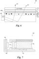
- FIG. 7 shows a backlight unit 700 that includes backplane 702, light guide panel 704, LED light source 706, mounting bracket 708, and a remote phosphor package in the form of a strip 710, mounted in the backplane 702.
- the remote phosphor part 710 is mounted via mounting bracket 708 between light guide panel 704 and LED light source 706, whereby light emitting from the backlight source 706 is transmitted through part 710 and then enters the light guide plate 704.
- the backlight unit may further include a bottom reflector plate arranged between light guide panel 704 and the backplane 702 and an optical film assembly arranged above the light guide plate 704.
- the LED radiationally coupled with the stabilized Mn 4+ doped phosphor may form part of a display device.
- the display device may include the Mn 4+ doped phosphor radiationally coupled to a light emitting diode, including a mini light emitting diode or a micro light emitting diode which emits light in the blue spectrum.
- a micro light emitting diode also known as a micro LED, micro LED, micro-LED, mLED, and pLED
- Such a display device may include a backlighting unit and a) the stabilized Mn 4+ doped phosphor being part of the back lighting unit of the display device and being in direct or indirect contact with the LED or micro LED, or b) the stabilized Mn 4+ doped phosphor being part of the back lighting unit and being remotely coupled to the LED or micro LED, and optionally being in the form of a film.
- the stabilized Mn 4+ doped phosphor may be operably connected to the back lighting unit through at least one filter, and the back lighting unit contains the light emitting diode or the micro light emitting diode.
- the Mn 4+ doped phosphor may be operably connected to or part of a back lighting unit of the display device in any way that is known in the art.
- the Mn 4+ doped phosphors according to the present invention are used in direct emission display devices that include arrays of microLEDs having dimensions on the scale of 1 to 300 mhi or, more specifically, i to 100 mhi, and even the scale of 1 to 50 p , 1 to 20 pm, or 1 to 10 pm.
- Exemplary methods for fabricating direct emission display devices that include phosphor particles in a wavelength conversion layer coupled to the microLEDs are described in US 9,111,464 , and US 9,627,437 .
- Devices that include a backlight unit or direct emission display according to the present invention include, but are not limited to, TVs, computers, smartphones, tablet computers and other handheld devices that have a display including a semiconductor light source; and a Mn 4+ doped phosphor according to the present invention.
- the phosphor particles of the present invention are a part of a device which comprises an LED, quantum dots, a mini LED, or a micro LED.
- a mini LED is an LED of a size between 50 pm and 300 pm.
- the display device may be a television, a computer monitor, a cellular or conventional phone, a digital photo frame, a tablet, an automotive display, an e-book reader, an electronic dictionary, a digital camera, an electronic keyboard, or a gaming device, or any other electronic device with a screen.
- Devices according to the present invention may include one or more other light emitting materials in addition to a Mn 4+ doped phosphor.
- the resultant light emitted by the assembly may be a white light.
- Other phosphors or quantum dot (QD) materials such as green, blue, yellow, red, orange, or other color phosphors or QD materials may be used in a blend to customize the color of the resulting light and produce specific spectral power distributions.
- the materials may be physically separated in a multilayered structure or may be present in one or more blends in a multilayered structure. In FIGS.
- phosphor composition 22 may be a single layer blend or a multilayered structure containing one or more phosphors or QD materials in each layer.
- individual microLEDs may be separately coupled to a Mn 4+ doped phosphor and other phosphors or quantum dot (QD) materials to yield light having desired specifications.
- QD quantum dot
- Suitable phosphors for use in devices according to the present invention, along with a Mn 4+ doped phosphor include, but are not limited to:
- Quantum dot (QD) materials for use in devices according to the present invention may be a group II -VI compound, a group III-V compound, a group IV-IV compound, a group IV compound, a group I-III-VI 2 compound or a combination thereof.
- group II-VI compounds include CdSe, CdTe, CdS, ZnSe, ZnTe, ZnS, HgTe, HgS, HgSe, CdSeTe, CdSTe, ZnSeS, ZnSeTe, ZnSTe, HgSeS, HgSeTe, HgSTe, CdZnS, CdZnSe, CdZnTe, CdHgS, CdHgSe, CdHgTe, HgZnS, HgZnSe, HgZnTe, CdZnSeS, CdZnSeTe, CdZnSTe, CdHgSeS, CdHgSeTe, CdHgSTe, HgZnSeS, HgZnSeTe, HgZnSTe, or combinations thereof.
- group ⁇ P-V compounds include GaN, GaP, GaAs, AIN, A1P, AlAs, InN, InP, InAs, GaNP, GaNAs, GaP As, A1NP, AlNAs, AlPAs, IriNP, InNAs, InP As, GaAlNP, GaAlNAs, GaAlPAs, GalnNP, GalnNAs, GalnPAs, InAlNP, InAlNAs, InAlPAs, and combinations thereof
- group IV compounds include Si, Ge, SiC, and SiGe.
- group I-III-VI 2 chalcopyrite-type compounds include CuInS ? ., CuInSe 2 , CuGaS 2 , CuGaSe ? , AgInS 2 , AglnSe ? ., AgGaS 2 , AgGaSe ? . And combinations thereof.
- the QD materials may be a core/shell QD, including a core, at least one shell coated on the core, and an outer coating including one or more ligands, preferably organic polymeric ligands.
- Exemplary materials for preparing core-shell QDs include, but are not limited to, Si, Ge, Sn, Se, Te, B, C (including diamond), P, Co, Au, BN, BP, BAs, AIN, A1P, AlAs, AlSb, GaN, GaP, GaAs, GaSb, InN, InP, InAs, InSb, AIN, A1P, AlAs, AlSb, GaN, GaP, GaAs, GaSb, ZnO, ZnS, ZnSe, ZnTe, CdS, CdSe, CdSeZn, CdTe, HgS, HgSe, HgTe, BeS, BeSe, BeTe, MgS, MgSe, MnS
- Exemplary core-shell QDs include, but are not limited to, CdSe/ZnS, CdSe/CdS, CdSe/CdS/ZnS, CdSeZn/CdS/ZnS, CdSeZn/ZnS, InP/ZnS, PbSe/PbS, PbSe/PbS, CdTe/CdS and CdTe/ZnS.
- the QD materials typically include ligands conjugated to, coordinated with, associated with, or attached to their surface.
- the QDs may include a coating layer comprising ligands to protect the QDs from environmental conditions including elevated temperatures, high intensity light, external gasses, and moisture.
- Such coating layer can also help to control aggregation, and allow for dispersion of the QDs in the matrix material.
- Phosphor composition for use in display or lighting devices may include one or more phosphors that result in a green spectral power distribution under ultraviolet, violet, or blue excitation. In the context of the present invention, this is referred to as a green phosphor or green phosphor material.
- the green phosphor may be a single composition or a blend that emits light in a green to yellow-green to yellow range, such as cerium-doped yttrium aluminum garnets, more particularly (Y,Gd,Lu,Tb) 3 (Al,Ga) 5 O 12 :Ce 3+ (YAG).
- an LED package 10 has a color temperature less than or equal to 4200°K, and the only red phosphor present in phosphor composition 22 is the Mn 4+ doped phosphor; in particular, K2SiF6:Mn 4+ .
- the composition may additionally include a green phosphor.
- the green phosphor may be a Ce 3+ -doped garnet or blend of garnets, particularly a Ce 3+ -doped yttrium aluminum garnet, and more particularly, YAG.
- the mass ratio of the red phosphor to the green phosphor material may be less than 3.3, which may be significantly lower than for red phosphors of similar composition, but having lower levels of the Mn dopant.
- Other green-emitting that may be used with the Mn 4+ doped phosphors include green-emitting QD materials and b-SiAlON.
- the ratio of each of the individual phosphors in a phosphor blend may vary depending on the characteristics of the desired light output.
- the relative proportions of the individual phosphors in the various embodiment phosphor blends may be adjusted such that when their emissions are blended and employed in an LED lighting device, there is produced visible light of predetermined x and y values on the CIE chromaticity diagram, and a white light is preferably produced.
- This white light may, for instance, possess an x value in the range of about 0.20 to about 0.55, and a y value in the range of about 0.20 to about 0.55.
- the exact identity and amounts of each phosphor in the phosphor composition can be varied according to the needs of the end user.
- the material can be used for LEDs intended for liquid crystal display (LCD) backlighting.
- the LED color point would be appropriately tuned based upon the desired white, red, green, and blue colors after passing through an LCD/color filter combination.
- the list of potential phosphors for blending given here is not meant to be exhaustive and these Mn 4+ -doped phosphors can be blended with various phosphors with different emission to achieve desired spectral power distributions.
- electroluminescent polymers such as polyfluorenes, preferably poly(9, 9-dioctyl fluorene) and copolymers thereof, such as poly(9,9'-dioctylfluorene-co-bis-N,N'-(4-butylphenyl)diphenylamine) (F8-TFB); poly(vinylcarbazole) and polyphenylenevinylene and their derivatives.
- the light emitting layer may include a blue, yellow, orange, green or red phosphorescent dye or metal complex, or a combination thereof.
- phosphorescent dye Materials suitable for use as the phosphorescent dye include, but are not limited to, tris(l-phenylisoquinoline) iridium (III) (red dye), tris(2-phenylpyridine) iridium (green dye) and Iridium (III) bis(2-(4,6-difluorephenyl)pyridinato-N,C2) (blue dye).
- fluorescent and phosphorescent metal complexes from ADS (American Dyes Source, Inc.) may also be used.
- ADS green dyes include ADS060GE, ADS061 GE, ADS063GE, and ADS066GE, ADS078GE, and ADS090GE.
- ADS blue dyes include ADS064BE, ADS065BE, and ADS070BE.
- ADS red dyes include ADS067RE, ADS068RE, ADS069RE, ADS075RE, ADS076RE, ADS067RE, and ADS077RE.
- the Mn 4+ doped phosphors of the present invention may be used in applications other than those described above.
- the material may be used as a phosphor in a fluorescent lamp, in a cathode ray tube, in a plasma display device or in an LCD, as explained above.
- the material may also be used as a scintillator in an electromagnetic calorimeter, in a gamma ray camera, in a computed tomography scanner or in a laser. These uses are merely exemplary and not limiting.
- the present invention is also directed to certain inventive phosphor compositions.
- the present invention may be directed to a phosphor composition comprising phosphor particles and comprising, on surfaces of the phosphor particles, at least one surface composition selected from the group consisting of: 1) a composition containing a phosphorus-containing moiety and a carbon-containing moiety; 2) a composition containing a phosphorus-containing moiety and a metal fluoride; 3) a composition containing a phosphorus-containing moiety and a carbon-containing moiety and a metal fluoride; and 4) a composition comprising the phosphorus-containing moiety free of an alkyl phosphate compound, wherein the phosphor particles comprise a Mn 4+ doped phosphor of formula I which is A x [MF y ]:Mn 4+ , where A is Li, Na, K, Rb, Cs, or a combination thereof; M is Si, Ge, Sn, Ti, Zr, Al, Ga, In, Sc, Y
- the surface composition containing a phosphorus-containing moiety may be formed by exposing the phosphor particles to K2HPO4.
- the surface composition containing a carbon-containing moiety may be formed by exposing the phosphor particles to one or more of polyoxyethylene octyl phenyl ether, potassium oleate, polyoxyethylene-polyoxypropylene block copolymer, polyoxyethylene (20) sorbitan monolaurate, poly(acrylic acid sodium salt), and potassium sorbate.
- the surface composition containing a phosphorus-containing moiety free of an alkylphosphate may be formed by exposing the phosphor particles to K2HPO4.
- the metal fluoride comprises magnesium fluoride.
- the compound containing phosphorus comprises a phosphate moiety; in the context of the present invention, 'phosphate' means an ion that contains PO4, and includes the phosphate ion, PO4 hydrogen phosphate ion, HPO4 2 , and dihydrogen phosphate ion, H 2 P(V.
- the compound containing carbon comprises at least one selected from the group consisting of: ethylenediaminetetraacetic acid, polyoxyethylene octyl phenyl ether, potassium oleate, polyoxyethylene-polyoxypropylene block copolymer, polyoxyethylene (20) sorbitan monolaurate, poly(acrylic acid sodium salt), potassium sorbate, and derivatives or salts thereof.
- the surface composition improves the quantum efficiency of the phosphor particles upon exposure to liquid water or water vapor.
- the phosphor particles exhibit A) a quantum efficiency after exposure to liquid water for one hour at room temperature that is 50% to 100% of the quantum efficiency exhibited before water exposure or B) a quantum efficiency loss upon exposure to 85% relative humidity at 85 deg C for 100 hours that is less than 40%.
- An advantage of the present invention is that the phosphor particles are less agglomerated than would otherwise be the case.
- a D 50 particle size of the phosphor particles before sonication of a solution containing the particles is no greater than 30 pm and the D 50 particle size of the phosphor particles after sonication is no greater than 20 pm.
- the phosphor particles are sufficiently not agglomerated that the use of sonication will result in less of a decrease in agglomeration than would occur with particles which are not treated pursuant to the present invention.
- Phosphor powders containing substantially unagglomerated particles may show improved flowability and dispersibility during LED package fabrication.
- a light emitting diode device is a structure which contains a light emitting diode.
- a light emitting diode device is radiationally coupled to and/or comprises the phosphor composition according to the present invention.
- the light emitting diode device is a mini LED or a micro LED.
- a light emitting diode device can comprise an LED chip on which the phosphor composition is deposited.
- the phosphor composition is optionally dispersed in a polymeric resin in a form of a film.
- the primary particle size was measured using a scanning electron microscope with procedures that are known in the art, and the secondary particle size was measured using a Horiba LA-950V2 Laser Scattering Particle Size Distribution Analyzer, also with procedures which are known in the art.
- Primary particle size according to the present application is the particle size of each phosphor particle, whether in agglomerated state or not.
- the secondary particle size according to the present application is the particle size of each discreet particle or unit of particles. For example, if two 10 pm phosphor particles are agglomerated with one another, the primary particle size would be 10 pm since that is the size of each of the basic phosphor particles. In this scenario, the secondary particle size would be more than 10 pm. For example, it may be 20 pm due to the agglomeration.
- QE Quantum efficiency
- This example is directed to a phosphor having chemical formula K 2 SiF 6 :Mn 4+ .
- This phosphor powder had an average primary particle size of 10.5 pm as determined by scanning electron microscopy. This phosphor was not stabilized as described in the present application nor exposed to a water test.
- Example 1 1.2g of the phosphor of Example 1 was mixed with 3.6g of a 39 mM solution of phosphoric acid in a 15 mL plastic bottle. The mixture was shaken by hand for 15 seconds and then rolled at 40 rpm for 1 hour. The mixture was filtered on Whatman #4 filter paper and washed 4 times with a total of 100 mL acetone. The powder was dried under vacuum for at least 18 hours. The powder was added to a fresh bottle and mixed with deionized water in a lg:3g ratio of powder to water. The mixture was shaken by hand for 15 seconds and then rolled at 40 rpm for 1 hour. The mixture was filtered on Whatman #4 filter paper and washed 4 times with a total of 100 mL acetone. The powder was dried under vacuum for at least 24 hours.
- Example 3 The experiment of Example 3 was repeated, replacing 39 mM phosphoric acid with 390 mM phosphoric acid.
- Example 3 The experiment of Example 3 was repeated, replacing 39 mM phosphoric acid with 39 mM oxalic acid.
- Example 3 The experiment of Example 3 was repeated, replacing 39 mM phosphoric acid with 390 mM oxalic acid.
- Example 3 The experiment of Example 3 was repeated, replacing 39 mM phosphoric acid with 39 mM potassium hydrogen phosphate, dibasic.
- Example 3 The experiment of Example 3 was repeated, replacing 39 mM phosphoric acid with 390 mM potassium hydrogen phosphate, dibasic (pH 9).
- Cured films of a 2-part thermally cured polydimethylsiloxane elastomer (such as is sold as Sylgard 184, from Dow Coming) comprising dispersed phosphor particles were prepared at a concentration of 0.5g of phosphor per 1.5g of silicone.
- the phosphors used were the ones prepared in Examples 1-8.
- the quantum efficiencies (QE) of the phosphor particles were measured in these films.
- the data in Table 1 shows that the robustness of K 2 SiF 6 :Mn 4+ phosphor is enhanced by a process comprising mixing K 2 SiF 6 :Mn 4+ with an aqueous solution of several substances, such as K 2 HPO 4 , followed by powder isolation and drying.
- Enhanced robustness is shown as a preservation of QE after mixing the treated phosphor powder with water for 1 hour, vs the QE of the untreated powder as produced mixed with water for 1 hour, relative to the QE of the starting phosphor powder without mixing with water.
- the QE of Example 1 is 105.6%, which is not treated with water.
- the QE of Example 2 is 74.6%, which shows that water can have a large detrimental effect on the QE of phosphors.
- Example 2 is not treated in accordance with the present invention.
- Example 3 is treated in accordance with the present invention and exhibits a QE of 86.2%, which is much higher than a QE of 74.6%.
- QE QE
- Even a small percentage change in QE is significant and phosphor manufacturers are routinely looking for ways to add even a few percentage points of QE to their phosphors.
- a jump from 74.6% to 86.2% is significant and surprising.
- the effect of treating the phosphor powder with an aqueous solution of K 2 HPO 4 was most pronounced in maintaining QE, since Examples 7 and 8 show a QE of 100.7% and 104.2%, respectively.
- This Example is directed to a phosphor having chemical formula K 2 SiF 6 :Mn 4+ .
- This phosphor was not stabilized as described in the present application nor exposed to a water test.
- the K 2 SiF 6 :Mn 4+ phosphor of Example 9 had an average primary particle size of 10.0 pm as determined by scanning electron microscopy. Furthermore, the phosphor of Example 9 was not treated with an HF solution of K 2 SiF 6 after annealing.
- Example 10 The phosphor used in Example 10 is the same as in Example 1, and both are treated with an HF solution saturated with K 2 SiF 6 after annealing.
- the Examples are duplicates of one another. The fact that they get similar results for QE means that this experiment is repeatable.
- a K 2 SiF 6 :Mn 4+ phosphor was utilized which has a smaller average primary particle size as Examples 1 and 9.
- the phosphor powder of Example 11 had an average primary particle size of 3.9 pm as determined by scanning electron microscopy and did not receive stabilizing treatment according to the present invention.
- a K 2 SiF 6 :Mn 4+ phosphor was utilized which has a smaller average particle size than Examples 1 and 9.
- the phosphor of Example 12 had an average primary particle size of 3.9 pm as determined by scanning electron microscopy and did not receive stabilizing treatment according to the present invention.
- Example 9 lg of each of the phosphor samples from Example 9, Example 1, Example 11, and Example 12, respectively, was mixed with 3g deionized water in a 15 mL plastic bottle. The mixtures were shaken by hand for 15 seconds and then rolled at 40 rpm for 1 hour. The mixtures were filtered on Whatman #4 filter paper and each washed 4 times with a total of 100 mL acetone. The powders were dried under vacuum for at least 24 hours.
- Example 9 1.2g of each of the phosphor samples from Example 9, Example 1, Example 11, and Example 12, respectively, was mixed with 3.6g of a 390 mM solution of potassium hydrogen phosphate, dibasic (pH 9), in a 15 mL plastic bottle. The mixtures were shaken by hand for 15 seconds and then rolled at 40 rpm for 1 hour. The mixtures were filtered on Whatman #4 filter paper and each washed 4 times with a total of 100 mL acetone. The powders were dried under vacuum for at least 18 hours. The powders were then added to a fresh bottle and mixed with deionized water in a lg:3g ratio of powder to deionized water.
- the mixtures were shaken by hand for 15 seconds and then rolled at 40 rpm for 1 hour.
- the mixtures were filtered on Whatman #4 filter paper and each washed 4 times with a total of 100 mL acetone.
- the powders were dried under vacuum for at least 24 hours.
- Example 1 1.2g of the phosphor sample of Example 1 was mixed with 3.6g of a 390 mM solution of potassium hydrogen phosphate, dibasic (pH 9), in a 15 mL plastic bottle. The mixture was shaken by hand for 15 seconds and then rolled at 40 rpm for 15 minutes. The mixture was filtered on Whatman #4 filter paper and then washed 4 times with a total of 100 mL acetone. The powder was dried under vacuum for 4 hours. The powder was then added to a fresh bottle and mixed with deionized water in a lg:3g ratio of powder to deionized water. The mixture was shaken by hand for 15 seconds and then rolled at 40 rpm for 1 hour. The mixture was filtered on Whatman #4 filter paper and then washed 4 times with a total of 100 mL acetone. The powder was dried under vacuum for at least 24 hours.
- Example 21 The experiment of Example 21 was repeated except that the aqueous 390 mM K2HPO4 solution mixed with the phosphor of Example 1 was rolled for 90 minutes instead of 15 minutes.
- 1.2g of phosphor from Example 1 was mixed with 3.6g of a 390 mM solution of potassium hydroxide (pH 13.5) in a 15 mL plastic bottle. The mixture was shaken by hand for 15 seconds and then rolled at 40 rpm for 1 hour. The mixture was filtered on Whatman #4 filter paper and then washed 4 times with a total of 100 mL acetone. The powder was dried under vacuum for 4 hours. The powder was then added to a fresh bottle and mixed with deionized water in a lg:3g ratio of powder to ionized water. The mixture was shaken by hand for 15 seconds and then rolled at 40 rpm for 1 hour. The mixture was filtered on Whatman #4 filter paper and then washed 4 times with a total of 100 mL acetone. The powder was dried under vacuum for at least 24 hours.
- Example 23 The experiment of Example 23 was repeated except that the 390 mM solution of KOH was replaced with a more dilute aqueous KOH solution adjusted to pH 9. Table 2. Measured QE values for the phosphor containing films of Examples 9-24. Description Ex Details QE Starting material (SM) 9 Starting material K 3 SiF 6 :Mn 4+ of Example 9 104.9% 10 Starting material K 2 SiF 6 :Mn 4+ of Example 1 104.8% 11 Starting material K 2 SiF 6 :Mn 4+ of Example 11 97.6% 12 Starting material K 2 SiF 6 :Mn 4+ of Example 12 98.5% Control samples: SM's mixed with water 13 K 2 SiF 6 :Mn 4+ of Example 9 mixed with water 62.7% 14 K 2 SiF 6 :Mn 4+ of Example 1 mixed with water 73.7% 15 K 2 SiF 6 :Mn 4+ of Example 11 mixed with water 25.0% 16 K 2 SiF 6 :Mn 4+ of Example 12 mixed with water 25.1% Effect of mixing
- this measure of stability or robustness is durable in the sense that the benefit persists even after isolation of the powder from the aqueous K2HPO4 treatment solution, washing and drying.
- the data shows that the stabilization of the powder is surprisingly fast since the QE of powder mixed with aqueous K2HPO4 for just 15 minutes was essentially the same as when the mixing time was 1 hour or even 90 minutes.
- 15 minutes of exposure to aqueous K2HPO4 resulted in a QE that was just as high as the QE after 90 minutes exposure.
- the phosphor powder is substantially stable in the K2HPO4 treatment solution over extended time periods in spite of the fact that the aqueous K2HPO4 is mostly water which is known to degrade phosphors.
- Examples 11, 12, 15 and 16 are untreated with K2HPO4 and include samples of small particle sizes.
- Examples 19 and 20 are both treated with K2HPO4 and include samples with small particle sizes. The results for Examples 19 and 20 show that the stabilization resulting from treatment of the phosphor powder with aqueous K2HPO4 is surprisingly high even when the K 2 SiF 6 :Mn 4+ powder has a primary particle size of 3.9 pm.
- Example 24 The surprising stabilization afforded upon treatment of the phosphor with aqueous K2HPO4 is not just a pH effect.
- Example 24 mixing phosphor powder with an aqueous solution of KOH that was pH-adjusted to match the pH of 390 mM K2HPO4 (see Examples 17-20) did not result in phosphor stabilization.
- the QE of Example 24 was just 51%, which is even lower than Example 14 (which was acidic with a pH of 3.28) which had a QE of 73.7% and which was not mixed with a stabilization agent.
- adjusting the pH with KOH to be basic resulted in a much worse result than adding no stabilization agent (Example 14).
- Example 23 A significant QE drop was also observed in Example 23 (QE of 75.6%) when the phosphor powder was mixed with aqueous KOH (pH 13.48) that matched the concentration of the K 2 HPO 4 solutions (390 mM) in Examples 17-22 where the lowest QE was 91.9%.
- Typical solvents ranged from non-polar hydrocarbon solvents such as 1-octadecene (ODE) to moderately polar isonorbomyl acrylate to polar aprotic propylene glycol monomethyl ether acetate (PGMEA).
- ODE 1-octadecene
- PGMEA polar aprotic propylene glycol monomethyl ether acetate
- Surfactant/dispersant additives included those that are non-ionic (oleylamine, oleic acid, polyoxyethylene octyl phenyl ether (which may be sold as Triton X-100)), anionic (potassium oleate) and cationic (polyethylene oxide derivatized fatty ammonium ethosulphate (which may be marketed as Hypermer KD25-LQ-(MV)). Examples 25-71 had secondary particle size d50 measured using light scattering.
- Example 25 is a control and consisted of 3g of K 2 SiF 6 :Mn 4+ powder having a secondary particle size d50 of 15.0mm. No solvent or surfactant/dispersant was added. This control was used to determine the values of the second column of Table 3 (Ad50 - ODE + roller (mm)).
- Example 26 had organic solvent and no surfactant, and was made by taking 3g of
- the powder was dried on the filter for no more than five minutes before being collected and dried in a vacuum desiccator for at least 4 hours.
- the dry powders were then sieved through a 170 mesh screen to improve flowability and then stored in a nitrogen purged box/cabinet until they could be analyzed for particle size distribution (PSD) and quantum efficiency (QE).
- PSD particle size distribution
- QE quantum efficiency
- the secondary particle size d50 was then compared with that measured for Example 25 and the difference or"delta" was recorded in the second column of Table 3.
- the Ad50 was -1.4pm, so the d50 of Example 26 was 1.4pm less than the d50 of Example 25.
- Examples 27-31 were made bytaking20 mL of ODE and combining it with 0.3g of a respective surfactant as identified on the first column of Table 3, and then adding 3g of K 2 SiF 6 :Mn 4+ powder from the same lot as Example 25. Then, the resulting composition was shaken briefly to mix and rolled at 80 rpm for 20-30 minutes. The resulting mixture was then vacuum filtered to collect the powder and rinsed with 3 x 20 mL of acetone to remove traces of solvent. Following the acetone wash the powder was dried on the filter for no more than five minutes before being collected and dried in a vacuum desiccator for at least 4 hours.
- the dry powders were then sieved through a 170 mesh screen to improve flowability and then stored in a nitrogen purged box/cabinet until they could be analyzed for secondary particle size and QE.
- the secondary particle size d50s were then compared with Example 25 and the difference for each, or"delta" was recorded at the second column of Table 3.
- Example 32 is a control and consists of 3g of K 2 SiF 6 :Mn 4+ powder having a secondary particle size d50 of 33.4 pm. No solvent or surfactant/dispersant was added. The QE of Example 32 was 92.8%. This control was used to determine the values of the third column of Table 3 (Ad50 - PGMEA + roller (pm)).
- Example 33 has organic solvent and no surfactant, and was made by taking 3g of K 2 SiFg:Mn 4+ powder from the same lot as Example 32 and mixing it with 20 mL of propylene glycol monomethyl ether acetate (PGMEA) which is an organic solvent. Then, the resulting composition was shaken briefly to mix and rolled at 80 rpm for 20-30 minutes. The resulting mixture was then vacuum filtered to collect the powder and rinsed with 3 x 20 mL of acetone to remove traces of solvent. Following the acetone wash the powder was dried on the filter for no more than five minutes before being collected and dried in a vacuum desiccator for at least 4 hours.
- PMEA propylene glycol monomethyl ether acetate
- the dry powder was then sieved through a 170 mesh screen to improve flowability and then stored in a nitrogen purged box/cabinet until it could be analyzed for PSD and QE.
- the secondary particle size distribution d50 was then compared with Example 32 and the difference or"delta"was recorded in Table 3, so Ad50 was -18.6 pm so the d50 of Example 33 was 18.6 pm less than the d50 of Example 32.
- Examples 34-38 were made by taking 20 mL of PGMEA and combining it with 0.3g of a particular surfactant as identified at column 1 of Table 3 and then adding 3g of K 2 SiF 6 :Mn 4+ powder from the same lot as Example 32. Then, the resulting composition was shaken briefly to mix and rolled at 80 rpm for 20-30 minutes. The resulting mixture was then vacuum filtered to collect the powder and rinsed with 3 x 20 mL of acetone to remove traces of solvent. Following the acetone wash the powder was dried on the filter for no more than five minutes before being collected and dried in a vacuum desiccator for at least 4 hours.
- the dry powders were then sieved through a 170 mesh screen to improve flowability and then stored in a nitrogen purged box/cabinet until they could be analyzed for PSD and QE.
- the particle size d50 was then compared with Example 32 and the differences or"deltas" was recorded in Table 3 at column 3.
- Example 39 is a control and consists of 3g of K 2 SiF 6 :Mn 4+ powder having a secondary particle size d50 of 35.2 pm. No solvent or surfactant/dispersant was added. The QE for this sample was determined to be 94.1%.
- Example 39 is the control used in conjunction with columns 4-6 of Table 3 (Ad50 - PGMEA + ultrasound (pm); Ad50 - acrylate + roller (pm); Ad50 - acrylate + ultrasound (pm), respectively).
- Example 40 had organic solvent and no surfactant, and was made by taking 3g of K 2 SiF 6 :Mn 4+ powder from the same lot as Example 39 and mixing it with 20 mL of isonorbomyl acrylate which is an organic solvent. Then, the resulting composition was shaken briefly to mix and rolled at 80 rpm for 20-30 minutes. The resulting mixture was then vacuum filtered to collect the powder and rinsed with 3 x 20 mL of acetone to remove traces of solvent. Following the acetone wash the powder was dried on the filter for no more than five minutes before being collected and dried in a vacuum desiccator for at least 4 hours.
- Example 39 The dry powders were then sieved through a 170 mesh screen to improve flowability and then stored in a nitrogen purged box/cabinet until they could be analyzed for secondary PSD and QE.
- the secondary particle size d50 was then compared with Example 39 and the difference or"delta" was recorded at column 5 of Table 3, so Ad50 was -19.4 pm so the d50 of Example 40 was 19.4 um less than the d50 of Example 39.
- Examples 41-47 were made by taking 20 mL of PGMEA (for Examples 41-43) or 20 mL of isonorbomyl acrylate (Examples 44-47) and combining each with 0.3 g of a surfactant identified at the last three lines of column 1 of Table 3. Subsequently, 3g of K 2 SiF 6 :Mn 4+ powder from the same lot as Example 39 was added. Then, the resulting composition was shaken briefly to mix and subjected to either an ultrasonic bath treatment for 7 minutes (Examples 41-43 and 47) or rolled at 80 rpm for 20-30 minutes (Examples 44-46).
- the resulting mixtures were then vacuum filtered to collect the powder and rinsed with 3 x 20 mL of acetone to remove traces of solvent. Following the acetone wash the powder was dried on the filter for no more than five minutes before being collected and dried in a vacuum desiccator for at least 4 hours. The dry powders were then sieved through a 170 mesh screen to improve flowability and then stored in a nitrogen purged box/cabinet until they could be analyzed for secondary PSD and QE. The secondary particle size d50 was then compared with Example 39 and the difference or"delta" was recorded in Table 3.
- Examples 41-43 are recorded at column 4 (Ad50 - PGMEA + ultrasound (pm)), Examples 44-46 are recorded at column 5 (Ad50 - acrylate + roller (pm)), and Example 47 is recorded at column 6 (Ad50 - acrylate + ultrasound (pm)) of Table 3.
- the absolute secondary particle size d50 (i.e., not relative to Example 39) of sample 41 is 12.9 pm and the QE was 88.4%.
- the absolute secondary particle size d50 (i.e., not relative to Example 39) of sample 42 was 12.0 pm and the QE is 94.3%.
- the absolute secondary particle size d50 (i.e., not relative to Example 39) d50 of sample 43 was 12.5 pm and the QE was 94.2 %. Table 3.
- the use of certain solvents can help reduce agglomeration.
- the use of certain surfactants can also reduce agglomeration.
- Certain combinations of solvents and surfactants exhibit advantages as well.
- the potassium oleate, polyoxyethylene octyl phenyl ether, and polyethylene oxide derivatized fatty ammonium ethosulphate (PODFAE) such as may be obtained as Hypermer KD25-LQ-(MV), as the leading anionic, non-ionic, and cationic additive candidates, respectively, resulted in a secondary particle size with absolute secondary d50 of 12 - 14 pm (i.e., not relative to another sample).
- the comparison to the controls is shown in Table 3.
- KEDTA ethylenediaminetetraacetic acid dipotassium salt dihydrate
- the material was then allowed to settle, the supernatant decanted and the slurry was vacuum filtered, rinsed once with 100 mL of H 2 O + 2 mL 30% H 2 0 2 , and then 5 times with 100 mL of acetone before drying under vacuum.
- MgSiF 6 6H 2 0 (17.6992g, 64.48 mmol) was weighed into a 60 mL plastic jar to which was then added 40g of high purity deionized water. After mixing, the slightly cloudy mixture was filtered through a 0.45 pm membrane. The filtered solution was diluted with 40 mL of 35% aq H 2 SiF 6 (52.8g, density 1.32). This made solution A. Separately, 125g of K 2 SiF 6 :Mn 4+ was added to a 2L mL plastic beaker containing a large stir bar.
- Each of two syringe pumps were set up to deliver 37.5 mL of solution A over 30 minutes (75 mL of solution A total) directly into the reaction mixture.
- To the beaker containing the phosphor powder was added 1.425L of aq 49% HF saturated with K 2 SiF 6 .
- the mixture was stirred vigorously for 30 sec (300 rpm) after which the stirring was turned down to 120 rpm.
- the addition of the solution A into the stirring reaction mixture via syringe pump was initiated. After the addition was complete, the stirring was stopped, the stir bar was removed and the reaction mixture was allowed to settle for 10 minutes. The supernatant was decanted and discarded.
- the wet slurry was mixed with 400 mL of 49% aq HF saturated with K 2 SiF 6 and MgF 2 .
- the wash mixture was allowed to settle for 10 minutes and then the supernatant was decanted and discarded.
- the slurry was transferred to a plastic Buchner funnel fitted with a 0.65 pm fluoropolymer membrane.
- the residual HF solution was filtered off and the phosphor cake was washed with acetone 4 times, using a total of 800 mL acetone, churning the solid before each wash.
- the product was dried under vacuum for 3 days and then sifted through a 170 mesh membrane to afford the final product.
- Table 4 The results of the testing of Examples 48-51 are shown at Table 4.
- the D50 secondary particle size of samples 48-51 were measured as follows:
- the Horiba measurement gives an agglomerated size, which is the size of the agglomerated masses of basic particles.
- the US measurement gives a minimally agglomerated size, which means that it is the agglomerated masses of basic particles decreased somewhat by the ultrasonication.
- the examples 48-51 show that the surface treatments and MgF 2 coating surprisingly produce a less agglomerated particle size with little to no drop in quantum efficiency.
- Examples 52-76 also show the concomitant maintenance of a good quantum efficiency with a reduction of agglomeration of particles, as explained below.
- Example 53 does not contain the surface agents of the present invention and is being compared to samples with surface agents.
- Examples 54-76 were made as follows: 4g K 2 SiF 6 :Mn 4+ from Example 52 was put in 20 mL H 2 0 or 20 mL 0.78M K 2 HPO 4 (aq) + 0.3 g or 0.6 g (or 0.3 mL) of surface agent in a 30 mL Nalgene bottle. The bottle was rolled for 30 minutes at 80 RPM. The sample was then settled for 20 minutes, subjected to a centrifuge pulse to 2500 RPM ( ⁇ 30 sec), then decanted, vacuum filtered, washed with acetone 3 times, vacuum dried, and sifted through 170 mesh. The information on the particulars of each Example is found in Table 5 below.
- the ammonium polyacrylate polymer in Examples 73 and 74 may be sold as Dispex AA 4040.
- Table 5 below shows at column 1, the "Example” number, at column 2, the surfactant or other "Surface Agent” that was used.
- K 2 HPO 4 this column is labeled as"0.78M K 2 HPO 4 ". If that column says Y, then 20 mL of 0.78M of K 2 HPO 4 was used, if it says N, then just 20mL of water was used. Column 3 may also indicate other additives which are added along with the K 2 HPO 4 or water, such as adding 1 mL of 30% aqueous solution of H2O2.
- At column 4, which is labeled as "Amount” lists whether the amount of "Surface Agent” used is 0.3 grams or 0.3 mL.
- the QE is shown.
- AQE which is the difference in QE between samples that included K 2 HPO 4 and those that did not.
- Example 77-84 3.5g of K 2 SiF 6 :Mn 4+ was added to a solution containing the surface agent listed at Table 6 in 15 mL of 0.39M K ⁇ FlPO ⁇ aq). The surface agent was provided in the amount listed in Table 6 as well.
- the samples were roll milled for 30 minutes. The material was then allowed to settle, the supernatant decanted and the slurry was vacuum filtered, rinsed once with 30 mL of H 2 O + 2 mL 30% H 2 O 2 , and then 5 times with 40 mL of acetone before drying under vacuum. The dried samples were then sieved through a 120 mesh nylon screen.
- Example 86 is the mother batch used for examples 77-85 and was not subject to water treatment.
- Example 85 was subject to water treatment but not to a surface agent.
- the results of the testing are shown at Table 6 with the first column giving the number of the Example, the second column identifying the surface agent used, the third column quantifying the amount of surface agent ("SA") used, and the fourth column providing the QE of such sample.
- SA surface agent
- SA surface agent
- the first column is the Example number.
- the second column shows the secondary particle sizes as measured without sonication.
- the third column shows the span with no sonication. Span measures the width of the particle size distribution.
- Examples 85 and 86 which were not treated with surface active agents, showed a relatively large span. Except for Example 80, the examples with surface active agents showed a decrease in span relative to Examples 85 and 86, which means that they showed better dispersion and less agglomeration since the spread of particle sizes was narrower.
- the fourth column is information on secondary particle size with sonication.
- In the fifth column is information on the span for the samples with sonication.
- Example 87 contained K 2 SiF 6 :Mn 4+ without any stabilizing treatment and which was also not exposed to a water test. This is the control used in conjunction with examples 88-95.
- Examples 88-95 were carried out to determine the effect of liquid water exposure of K 2 SiF 6 :Mn 4+ in the presence of AIPO 4 .
- 1.2 g samples of K 2 SiF 6 :Mn 4+ was combined with, respectively, 3.6 mL of high purity deionized water, 0.39 M K 2 HPO 4 , 0.39 M AIPO 4 , 0.39 M AIPO 4 plus 0.3 mL 30% H 2 0 2 , 0.1 M A1PO 4 , 0.1 M AlPO 4 plus 0.3 mL 30% H 2 0 2 , 0.6 M AIPO 4 , and 0.6 M AIPO 4 plus 0.3 mL of 30% H 2 0 2 .
- Examples 96-100 are directed towards the improvement of phosphor robustness towards liquid water and water vapor upon treatment with MgF 2 with and without potassium hydrogen phosphate treatment.
- the starting K 2 SiF 6 :Mn 4+ phosphor powder had an average secondary d50 particle size of 12.3 pm as determined by light scattering.
- Example 96 5g of the starting phosphor of Example 96 was coated with MgF 2 using the amount of MgSiF 6 6H 2 0 precursor that produces MgF 2 in the amount of 1% by weight with respect to the starting phosphor, according to the procedure defined in Example 51.
- lg of the coated phosphor was mixed with 3g deionized water in a 15 mL plastic bottle. The mixture was shaken by hand for 15 seconds and then rolled at 40 rpm for 1 hour. The mixture was filtered on Whatman #4 filter paper and washed 4 times with a total of 100 mL acetone. The powder was dried under vacuum for 3 days.
- Example 96 5g of the starting phosphor of Example 96 was coated with MgF 2 using the amount of MgSiF 6 6H 2 0 precursor that produces MgF 2 in the amount of 1% by weight with respect to the starting phosphor, according to the procedure defined in Example 51.
- the semi-dry cake was transferred back into the reaction beaker.
- To this solid was added 30 mL of 0.39M aqueous K2HPO4. The mixture was mixed at 140 rpm for 2 minutes. The slurry was transferred to a fresh plastic Buchner funnel fitted with a 0.7 pm paper membrane (Whatman GF/F). The aqueous solution was filtered off.
- Example 96 5g of the starting phosphor of Example 96 was coated with MgF 2 using the amount of MgSiF 6 6H 2 0 precursor that produces MgF 2 in the amount of 5% by weight with respect to the starting phosphor, according to the procedure defined in Example 51.
- lg of the starting phosphor was mixed with 3g deionized water in a 15 mL plastic bottle. The mixture was shaken by hand for 15 seconds and then rolled at 40 rpm for 1 hour. The mixture was filtered on Whatman #4 filter paper and washed 4 times with a total of 100 mL acetone.
- the powder was dried under vacuum for 3 days.
- Example 96 5g of the starting phosphor of Example 96 was coated with MgF 2 using the amount of MgSiF 6 6F1 2 0 precursor that produces MgF 2 in the amount of 5% by weight with respect to the starting phosphor, according to the procedure defined in Example 51.
- the semi-dry cake was transferred back into the reaction beaker.
- To this solid was added 30 mL of 0.39M aqueous K 2 HPO 4 .
- the mixture was mixed at 140 rpm for 2 minutes.
- the slurry was transferred to a fresh plastic Buchner funnel fitted with a 0.7 pm paper membrane (Whatman GF/F). The aqueous solution was filtered off.
- Example 96 After mixing the starting phosphor in water for 1 hour, the QE dropped from 99.9% to 16.8% as shown in Table 9 (Example 96). By comparison, the phosphor coated at the 1% MgF 2 level dropped down only to 77.6% (Example 97), and the phosphor coated at the 5% MgF 2 level only dropped down to 93.3% (Example 99). Incorporating treatment of the MgF 2 -coated phosphor with aqueous K 2 HPO 4 , by simply mixing the MgF 2 -coated product with 0.39M aqueous K 2 HPO 4 for 2 minutes, resulted in an even more significant preservation of QE upon exposure to liquid water.
- coating the phosphor with MgF 2 with and without subsequent treatment with aqueous K2HPO4 has three benefits: it enhances dispersibility, it enhances robustness against liquid water, and it enhances robustness against humidity at elevated temperature. These effects are enhanced further still in compositions of the present invention wherein the phosphor coated with MgF 2 is subsequently treated with aqueous K 2 HP04.
Landscapes
- Chemical & Material Sciences (AREA)
- Physics & Mathematics (AREA)
- Engineering & Computer Science (AREA)
- Materials Engineering (AREA)
- Organic Chemistry (AREA)
- Optics & Photonics (AREA)
- General Physics & Mathematics (AREA)
- Inorganic Chemistry (AREA)
- Spectroscopy & Molecular Physics (AREA)
- General Engineering & Computer Science (AREA)
- Luminescent Compositions (AREA)
- Optical Filters (AREA)
- Planar Illumination Modules (AREA)
- Led Device Packages (AREA)
Claims (10)
- Verfahren, umfassend Kombinieren a) einer Lösung, umfassend mindestens eine Substanz, die ausgewählt ist aus der Gruppe bestehend aus K2HPO4, einem Aluminiumphosphat, Oxalsäure oder einer Kombination davon, mit b) einem Mn4+-dotierten Phosphor nach Formel I in fester Form;
Ax [MFy]:Mn4+ I
und Isolieren eines stabilisierten Mn4+-dotierten Phosphors in fester Form; wobei A Li, Na, K, Rb, Cs oder eine Kombination davon ist;M Si, Ge, Sn, Ti, Zr, Al, Ga, In, Sc, Y, La, Nb, Ta, Bi, Gd, oder eine Kombination davon ist;x der absolute Wert der Ladung des [MFy]-Ions ist;y 5, 6 oder 7 ist, ferner umfassend, vor dem Kombinieren mit der mindestens einen Substanz, Inkontaktbringen des Mn4+-dotierten Phosphors nach Formel I mit einem fluorhaltigen Oxidationsmittel in gasförmiger Form bei einer erhöhten Temperatur, um ein Produktphosphor auszubilden. - Verfahren gemäß Anspruch 1, wobeiM Si, Ge, Ti oder eine Kombination davon ist;A Na, K oder eine Kombination davon ist;oder wobei das Phosphor nach Formel I Folgendes ist:
K2SiF6:Mn4+
oder wobei die mindestens eine Substanz K2HPO4 umfasst,oder wobei die Lösung wässrig ist und zusätzlich H2O2 umfasst,oder wobei die mindestens eine Substanz mindestens eines ausgewählt aus der Gruppe bestehend aus Polyoxyethylen-Octylphenylether, Kaliumoleat, Polyoxyethylen-Polyoxypropylen-Block-Copolymer; Polyoxyethylen (20)-Sorbitan-Monolaurat, Poly(acrylsäure-Natriumsalz) und Kaliumsorbat umfasst,oder wobei das Mn4+-dotierte Phosphor nach Formel I einen Kern umfasst, der ein Phosphor nach Formel I und eine auf den Kern aufgebrachte Kompositbeschichtung umfasst, wobei die Kompositbeschichtung ein Metallfluorid umfasst, das ausgewählt ist aus der Gruppe bestehend aus Calciumfluorid, Strontiumfluorid, Magnesiumfluorid, Yttriumfluorid, Scandiumfluorid, Lanthanfluorid und Kombinationen davon. - Verfahren gemäß Anspruch 1, wobei die Lösung zusätzlich mindestens ein Lösungsmittel umfasst, das ausgewählt ist aus der Gruppe bestehend aus 1-Octadecan, Isonorbonylacrylat, Wasser und Propylenglycolmonomethyletheracetat.
- Zusammensetzung, umfassend a) mindestens eine Substanz umfassend K2HPO4 und Magnesiumfluorid, wobei die Zusammensetzung ein Mn4+-dotiertes Phosphor nach Formel I umfasst;
Ax[MFy]:Mn4+ I
wobeiA Li, Na, K, Rb, Cs oder eine Kombination davon ist;M Si, Ge, Sn, Ti, Zr, Al, Ga, In, Sc, Y, La, Nb, Ta, Bi, Gd, oder eine Kombination davon ist;x der absolute Wert der Ladung des [MFy]-Ions ist; y 5, 6 oder 7 ist. - Zusammensetzung nach Anspruch 4, wobeiM Si, Ge, Ti oder eine Kombination davon ist;A Na, K oder eine Kombination davon ist;oder wobei das Phosphor nach Formel I K2SiF6:Mn4+ ist,oder wobei das Mn4+-dotierte Phosphor nach Formel I einen Kern umfasst, der ein Phosphor nach Formel I und eine auf den Kern aufgebrachte manganfreie Kompositbeschichtung umfasst, wobei die manganfreie Kompositbeschichtung eine Verbindung nach Formel III und ein Metallfluorid umfasst, das ausgewählt ist aus der Gruppe bestehend aus Calciumfluorid, Strontiumfluorid, Magnesiumfluorid, Yttriumfluorid, Scandiumfluorid, Lanthanfluorid und Kombinationen davon.
A1 x[M1Fy] (III)
wobei A1 H, Li, Na, K, Rb, Cs oder eine Kombination davon ist; M1 Si, Ge, Sn, Ti, Zr, Al, Ga, In, Sc, Y, La, Nb, Ta, Bi, Gd oder eine Kombination davon ist; x der absolute Wert der Ladung des [M1Fy]-Ions ist; und y 5, 6 oder 7 ist. - Phosphorzusammensetzung, umfassend Phosphorpartikel und umfassend mindestens eine Oberflächenzusammensetzung auf Oberflächen der Phosphorpartikel, die ausgewählt ist aus der Gruppe bestehend aus: 1) einer Zusammensetzung, die einen phosphorhaltigen Anteil und einen kohlenstoffhaltigen Anteil umfasst; 2) eine Zusammensetzung, die den phosphorhaltigen Anteil und ein Metallfluorid umfasst; 3) eine Zusammensetzung, die den phosphorhaltigen Anteil und den kohlenstoffhaltigen Anteil und das Metallfluorid umfasst; und 4) eine Zusammensetzung, die einen phosphorhaltigen Anteil umfasst, der frei von einer Alkylphosphatverbindung ist, wobei die Phosphorpartikel ein Mn4+-dotiertes Phosphor nach Formel I umfassen;
Ax[MFy]:Mn4+ I
wobeiA Li, Na, K, Rb, Cs oder eine Kombination davon ist;M Si, Ge, Sn, Ti, Zr, Al, Ga, In, Sc, Y, La, Nb, Ta, Bi, Gd, oder eine Kombination davon ist;x der absolute Wert der Ladung des [MFy]-Ions ist;y 5, 6 oder 7 ist, undwobei eine D 50 Partikelgröße der Phosphorpartikel vor einer Beschallung einer die Partikel enthaltenden Suspension nicht größer als 30 µm ist und die D 50 Partikelgröße der Phosphorpartikel nach einer Beschallung nicht größer als 20 µm ist. - Phosphorzusammensetzung nach Anspruch 6, wobei das Metallfluorid Magnesiumfluorid umfasst,
oder wobei der phosphorhaltige Anteil einen Phosphatanteil umfasst, oder wobei der kohlenstoffhaltige Anteil mindestens eines ausgewählt aus der Gruppe bestehend aus Ethylendiamintetraessigsäure, Polyoxyethylen-Octylphenolether, Kaliumoleat, Polyoxyethylen-Polyoxypropylen-Block-Copolymer; Polyoxyethylen (20)-SorbitanMonolaurat, Poly(acrylsäure-Natriumsalz) und Kaliumsorbat und Derivaten oder Salzen davon umfasst, oder wobei die Phosphorpartikel A) eine Quantenausbeute nach Exposition gegenüber flüssigem Wasser für eine Stunde bei Raumtemperatur aufweisen, die 50 % bis 100 % der vor der Wasserexposition aufgewiesenen Quantenausbeute beträgt, oder B) einen Quantenausbeuteverlust bei Exposition gegenüber 85 % relativer Feuchte bei 85 Grad C für 100 Stunden aufweisen, der weniger als 40 % beträgt. - Anzeigevorrichtung, umfassend die Phosphorzusammensetzung nach Anspruch 7.
- Lichtemittierende Diodenvorrichtung, die strahlungsmäßig mit der Phosphorzusammensetzung nach Anspruch 7 gekoppelt ist und/oder diese umfasst.
- Lichtemittierende Diodenvorrichtung nach Anspruch 9, wobei die lichtemittierende Diodenvorrichtung eine Mini-LED oder eine Mikro-LED ist,
oder wobei a) die lichtemittierende Diodenvorrichtung einen LED-Chip umfasst, auf dem die Phosphorzusammensetzung aufgetragen ist, und/oder b) die Zusammensetzung in einem Polymerharz in Form eines Films dispergiert ist.
Applications Claiming Priority (2)
| Application Number | Priority Date | Filing Date | Title |
|---|---|---|---|
| US16/419,206 US11261375B2 (en) | 2019-05-22 | 2019-05-22 | Method to enhance phosphor robustness and dispersability and resulting phosphors |
| PCT/US2020/028946 WO2020236374A1 (en) | 2019-05-22 | 2020-04-20 | Method to enhance phosphor robustness and dispersability and resulting phosphors |
Publications (4)
| Publication Number | Publication Date |
|---|---|
| EP3973034A1 EP3973034A1 (de) | 2022-03-30 |
| EP3973034A4 EP3973034A4 (de) | 2023-03-01 |
| EP3973034B1 true EP3973034B1 (de) | 2025-06-04 |
| EP3973034C0 EP3973034C0 (de) | 2025-06-04 |
Family
ID=73457438
Family Applications (1)
| Application Number | Title | Priority Date | Filing Date |
|---|---|---|---|
| EP20809356.7A Active EP3973034B1 (de) | 2019-05-22 | 2020-04-20 | Verfahren zur erhöhung der leuchtstoffrobustheit und -dispergierbarkeit und resultierende leuchtstoffe |
Country Status (6)
| Country | Link |
|---|---|
| US (2) | US11261375B2 (de) |
| EP (1) | EP3973034B1 (de) |
| JP (1) | JP2022533904A (de) |
| KR (1) | KR102827904B1 (de) |
| CN (2) | CN113646409B (de) |
| WO (1) | WO2020236374A1 (de) |
Families Citing this family (9)
| Publication number | Priority date | Publication date | Assignee | Title |
|---|---|---|---|---|
| US11193059B2 (en) * | 2016-12-13 | 2021-12-07 | Current Lighting Solutions, Llc | Processes for preparing color stable red-emitting phosphor particles having small particle size |
| US11261375B2 (en) * | 2019-05-22 | 2022-03-01 | General Electric Company | Method to enhance phosphor robustness and dispersability and resulting phosphors |
| US11312876B2 (en) | 2020-04-14 | 2022-04-26 | General Electric Company | Ink compositions with narrow band emission phosphor materials |
| WO2021211600A1 (en) | 2020-04-14 | 2021-10-21 | General Electric Company | Green-emitting phosphors and devices thereof |
| WO2022051302A1 (en) | 2020-09-01 | 2022-03-10 | General Electric Company | Devices compatible with night vision equipment |
| EP4324034A4 (de) * | 2021-04-13 | 2025-04-09 | General Electric Company | Phosphore auf uranbasis und zusammensetzungen für anzeigen und beleuchtungsanwendungen |
| JP7445155B2 (ja) * | 2021-06-21 | 2024-03-07 | 日亜化学工業株式会社 | フッ化物蛍光体及びその製造方法、波長変換部材並びに発光装置 |
| CN115975625A (zh) * | 2022-12-09 | 2023-04-18 | 盐城工学院 | 一种Mn(IV)掺杂的氟硅酸钾红色荧光粉的改性方法 |
| WO2025178920A1 (en) | 2024-02-19 | 2025-08-28 | Edison Innovations, Llc | Devices including reflective geometries for displays and lighting applications |
Family Cites Families (49)
| Publication number | Priority date | Publication date | Assignee | Title |
|---|---|---|---|---|
| US3576756A (en) | 1968-06-12 | 1971-04-27 | Mallinckrodt Chemical Works | Fluocomplexes of titanium, silicon, tin and germanium, activated by tetravalent manganese |
| KR20010004094A (ko) | 1999-06-28 | 2001-01-15 | 김영환 | 형광체 페이스트 제조 장치 및 그를 이용한 형광체 제조 방법 |
| DE10126958A1 (de) | 2001-06-01 | 2002-12-05 | Philips Corp Intellectual Pty | Flüssigkristallbildschirm mit verbesserter Hintergrundbeleuchtung |
| JP2003336045A (ja) | 2002-05-20 | 2003-11-28 | Konica Minolta Holdings Inc | 蛍光体及び蛍光体の製造方法 |
| US7294610B2 (en) | 2004-03-03 | 2007-11-13 | 3M Innovative Properties Company | Fluorinated sulfonamide surfactants for aqueous cleaning solutions |
| US7358542B2 (en) | 2005-02-02 | 2008-04-15 | Lumination Llc | Red emitting phosphor materials for use in LED and LCD applications |
| US7648649B2 (en) | 2005-02-02 | 2010-01-19 | Lumination Llc | Red line emitting phosphors for use in led applications |
| US7497973B2 (en) | 2005-02-02 | 2009-03-03 | Lumination Llc | Red line emitting phosphor materials for use in LED applications |
| US8274215B2 (en) | 2008-12-15 | 2012-09-25 | Intematix Corporation | Nitride-based, red-emitting phosphors |
| JP5375733B2 (ja) | 2010-04-30 | 2013-12-25 | 住友金属鉱山株式会社 | 耐湿性に優れた被覆膜付き酸化物蛍光体粒子の製造方法 |
| EP2601042B1 (de) | 2010-08-06 | 2022-03-23 | Immunolight, Llc. | Farbverstärkung mithilfe von aufwärtswandlern und abwärtswandlern |
| US20120138874A1 (en) | 2010-12-02 | 2012-06-07 | Intematix Corporation | Solid-state light emitting devices and signage with photoluminescence wavelength conversion and photoluminescent compositions therefor |
| CN102220131A (zh) | 2011-04-02 | 2011-10-19 | 重庆文理学院 | 一种白光led用球形、增红荧光粉及其制备方法 |
| MY161542A (en) | 2011-04-08 | 2017-04-28 | Shinetsu Chemical Co | Preparation of complex fluoride and complex fluoride phosphor |
| WO2013078251A1 (en) | 2011-11-22 | 2013-05-30 | Qd Vision, Inc. | Stress-resistant component for use with quantum dots |
| BR112014020044B1 (pt) * | 2012-02-16 | 2021-03-02 | Lumileds Holding B.V. | unidade de iluminação; método de preparação de um material luminescente particulado; e material luminescente particulado |
| JP5884717B2 (ja) | 2012-12-19 | 2016-03-15 | 住友金属鉱山株式会社 | 被覆膜付き硫化物蛍光体粒子含有シリコーン樹脂硬化体及びその製造方法 |
| TWI498791B (zh) | 2012-12-27 | 2015-09-01 | Toppan Printing Co Ltd | 液晶顯示裝置、彩色濾光片基板及彩色濾光片基板之製造方法 |
| KR101878318B1 (ko) * | 2012-12-28 | 2018-07-16 | 신에쓰 가가꾸 고교 가부시끼가이샤 | 형광체의 표면 처리 방법 |
| US9698314B2 (en) | 2013-03-15 | 2017-07-04 | General Electric Company | Color stable red-emitting phosphors |
| US9484504B2 (en) | 2013-05-14 | 2016-11-01 | Apple Inc. | Micro LED with wavelength conversion layer |
| US9111464B2 (en) | 2013-06-18 | 2015-08-18 | LuxVue Technology Corporation | LED display with wavelength conversion layer |
| JP5783302B2 (ja) * | 2013-07-03 | 2015-09-24 | 日亜化学工業株式会社 | フッ化物蛍光体及びそれを用いた発光装置並びに蛍光体の製造方法 |
| US9388336B2 (en) | 2013-12-13 | 2016-07-12 | General Electric Company | Processes for preparing color stable manganese-doped complex fluoride phosphors |
| US10927267B2 (en) | 2014-03-31 | 2021-02-23 | Ppg Industries Ohio, Inc. | Infrared fluorescent coatings |
| US10563121B2 (en) | 2014-06-12 | 2020-02-18 | Current Lighting Solutions, Llc | Red-emitting phosphors and associated devices |
| JP2016027077A (ja) * | 2014-06-30 | 2016-02-18 | パナソニックIpマネジメント株式会社 | 表面処理蛍光体の製造方法、この方法で得られた表面処理蛍光体、並びにこれを用いた波長変換部材及び発光装置 |
| CN106717120A (zh) | 2014-10-01 | 2017-05-24 | 索尼公司 | 显示装置和电子设备 |
| US9982190B2 (en) | 2015-02-20 | 2018-05-29 | General Electric Company | Color stable red-emitting phosphors |
| CN106244143B (zh) | 2015-06-04 | 2019-08-27 | 隆达电子股份有限公司 | 具有优选方向的荧光粉、其制备方法及包含其的发光元件封装结构 |
| US9911861B2 (en) | 2015-08-03 | 2018-03-06 | Semiconductor Energy Laboratory Co., Ltd. | Semiconductor device, manufacturing method of the same, and electronic device |
| TWI564367B (zh) | 2015-11-16 | 2017-01-01 | 隆達電子股份有限公司 | 氟化物螢光粉、其製備方法及包含其之發光裝置與背光模組 |
| US10754081B2 (en) | 2016-03-07 | 2020-08-25 | Current Lighting Solutions, Llc | Devices containing a remote phosphor package with red line emitting phosphors and green emitting quantum dots |
| JP6485467B2 (ja) * | 2016-03-30 | 2019-03-20 | 日亜化学工業株式会社 | 蛍光体、発光装置及び蛍光体の製造方法 |
| US20170329770A1 (en) * | 2016-05-10 | 2017-11-16 | QUADROtech Solutions AG | System and method for facilitating data migration |
| US9627437B1 (en) | 2016-06-30 | 2017-04-18 | Sharp Laboratories Of America, Inc. | Patterned phosphors in through hole via (THV) glass |
| WO2018093832A2 (en) | 2016-11-17 | 2018-05-24 | General Electric Company | Coated red line emitting phosphors |
| US11193059B2 (en) * | 2016-12-13 | 2021-12-07 | Current Lighting Solutions, Llc | Processes for preparing color stable red-emitting phosphor particles having small particle size |
| US10793773B2 (en) * | 2017-03-16 | 2020-10-06 | Current Lighting Solutions, Llc | Color stable red-emitting phosphors |
| KR20190007130A (ko) | 2017-07-11 | 2019-01-22 | 삼성디스플레이 주식회사 | 표시 장치 |
| TW201915144A (zh) * | 2017-09-13 | 2019-04-16 | 美商奇異電器公司 | 用於製備顏色穩定之紅色發光磷光體之方法 |
| TWI732041B (zh) * | 2017-09-14 | 2021-07-01 | 美商現代照明解決方案公司 | 具有發射紅光磷光體之複合材料 |
| US10720554B2 (en) | 2017-09-20 | 2020-07-21 | General Electric Company | Green-emitting phosphors and devices thereof |
| US20190280165A1 (en) | 2018-03-08 | 2019-09-12 | General Electric Company | Devices including green-emitting phosphors |
| US20200028033A1 (en) | 2018-03-08 | 2020-01-23 | General Electric Company | Devices including green-emitting phosphors |
| JP6922939B2 (ja) | 2019-03-18 | 2021-08-18 | セイコーエプソン株式会社 | 波長変換素子、光源装置、プロジェクター、及び波長変換素子の製造方法 |
| JP7238506B2 (ja) | 2019-03-18 | 2023-03-14 | セイコーエプソン株式会社 | 波長変換素子、光源装置及びプロジェクター |
| JP7279436B2 (ja) | 2019-03-18 | 2023-05-23 | セイコーエプソン株式会社 | 波長変換素子、光源装置、プロジェクター、及び波長変換素子の製造方法 |
| US11261375B2 (en) * | 2019-05-22 | 2022-03-01 | General Electric Company | Method to enhance phosphor robustness and dispersability and resulting phosphors |
-
2019
- 2019-05-22 US US16/419,206 patent/US11261375B2/en active Active
-
2020
- 2020-04-20 JP JP2021560923A patent/JP2022533904A/ja active Pending
- 2020-04-20 KR KR1020217041809A patent/KR102827904B1/ko active Active
- 2020-04-20 CN CN202080025845.XA patent/CN113646409B/zh active Active
- 2020-04-20 EP EP20809356.7A patent/EP3973034B1/de active Active
- 2020-04-20 WO PCT/US2020/028946 patent/WO2020236374A1/en not_active Ceased
- 2020-04-20 CN CN202310994966.0A patent/CN117025197A/zh active Pending
-
2022
- 2022-01-18 US US17/578,335 patent/US11746288B2/en active Active
Also Published As
| Publication number | Publication date |
|---|---|
| US20200369956A1 (en) | 2020-11-26 |
| KR20210158413A (ko) | 2021-12-30 |
| US11261375B2 (en) | 2022-03-01 |
| WO2020236374A1 (en) | 2020-11-26 |
| CN113646409A (zh) | 2021-11-12 |
| CN117025197A (zh) | 2023-11-10 |
| JP2022533904A (ja) | 2022-07-27 |
| US20220135876A1 (en) | 2022-05-05 |
| EP3973034A1 (de) | 2022-03-30 |
| KR102827904B1 (ko) | 2025-06-30 |
| EP3973034A4 (de) | 2023-03-01 |
| EP3973034C0 (de) | 2025-06-04 |
| CN113646409B (zh) | 2024-03-29 |
| US11746288B2 (en) | 2023-09-05 |
Similar Documents
| Publication | Publication Date | Title |
|---|---|---|
| EP3973034B1 (de) | Verfahren zur erhöhung der leuchtstoffrobustheit und -dispergierbarkeit und resultierende leuchtstoffe | |
| US20240228874A1 (en) | Processes for preparing color stable red-emitting phosphor particles having small particle size | |
| US9868898B2 (en) | Processes for preparing color stable red-emitting phosphors | |
| EP3541891B1 (de) | Beschichtete rotlinienemittierende phosphore | |
| US11060023B2 (en) | Coated manganese doped phosphors | |
| US10072206B2 (en) | Processes for preparing color stable red-emitting phosphors | |
| TW201915144A (zh) | 用於製備顏色穩定之紅色發光磷光體之方法 | |
| US9938457B1 (en) | Methods for fabricating devices containing red line emitting phosphors | |
| WO2019054979A1 (en) | METHODS FOR PREPARING COLOR-STABLE RED EMITTING LUMINOPHORES | |
| TW201915145A (zh) | 色彩安定之發紅光磷光體之製法 | |
| WO2019054986A1 (en) | METHODS FOR PREPARING PHOSPHORES EMITTING IN STABLE COLOR RED |
Legal Events
| Date | Code | Title | Description |
|---|---|---|---|
| STAA | Information on the status of an ep patent application or granted ep patent |
Free format text: STATUS: THE INTERNATIONAL PUBLICATION HAS BEEN MADE |
|
| PUAI | Public reference made under article 153(3) epc to a published international application that has entered the european phase |
Free format text: ORIGINAL CODE: 0009012 |
|
| STAA | Information on the status of an ep patent application or granted ep patent |
Free format text: STATUS: REQUEST FOR EXAMINATION WAS MADE |
|
| 17P | Request for examination filed |
Effective date: 20211115 |
|
| AK | Designated contracting states |
Kind code of ref document: A1 Designated state(s): AL AT BE BG CH CY CZ DE DK EE ES FI FR GB GR HR HU IE IS IT LI LT LU LV MC MK MT NL NO PL PT RO RS SE SI SK SM TR |
|
| DAV | Request for validation of the european patent (deleted) | ||
| DAX | Request for extension of the european patent (deleted) | ||
| REG | Reference to a national code |
Ref country code: DE Free format text: PREVIOUS MAIN CLASS: C09K0011670000 Ipc: C09K0011610000 Ref country code: DE Ref legal event code: R079 Ref document number: 602020052381 Country of ref document: DE Free format text: PREVIOUS MAIN CLASS: C09K0011670000 Ipc: C09K0011610000 |
|
| A4 | Supplementary search report drawn up and despatched |
Effective date: 20230127 |
|
| RIC1 | Information provided on ipc code assigned before grant |
Ipc: C09K 11/02 20060101ALI20230123BHEP Ipc: H01L 33/50 20100101ALI20230123BHEP Ipc: C09K 11/61 20060101AFI20230123BHEP |
|
| STAA | Information on the status of an ep patent application or granted ep patent |
Free format text: STATUS: EXAMINATION IS IN PROGRESS |
|
| 17Q | First examination report despatched |
Effective date: 20231106 |
|
| RAP1 | Party data changed (applicant data changed or rights of an application transferred) |
Owner name: GE INTELLECTUAL PROPERTY LICENSING, LLC |
|
| GRAP | Despatch of communication of intention to grant a patent |
Free format text: ORIGINAL CODE: EPIDOSNIGR1 |
|
| STAA | Information on the status of an ep patent application or granted ep patent |
Free format text: STATUS: GRANT OF PATENT IS INTENDED |
|
| RIC1 | Information provided on ipc code assigned before grant |
Ipc: F21V 8/00 20060101ALN20241209BHEP Ipc: H01L 33/50 20100101ALI20241209BHEP Ipc: C09K 11/02 20060101ALI20241209BHEP Ipc: C09K 11/61 20060101AFI20241209BHEP |
|
| INTG | Intention to grant announced |
Effective date: 20241218 |
|
| GRAS | Grant fee paid |
Free format text: ORIGINAL CODE: EPIDOSNIGR3 |
|
| GRAA | (expected) grant |
Free format text: ORIGINAL CODE: 0009210 |
|
| STAA | Information on the status of an ep patent application or granted ep patent |
Free format text: STATUS: THE PATENT HAS BEEN GRANTED |
|
| AK | Designated contracting states |
Kind code of ref document: B1 Designated state(s): AL AT BE BG CH CY CZ DE DK EE ES FI FR GB GR HR HU IE IS IT LI LT LU LV MC MK MT NL NO PL PT RO RS SE SI SK SM TR |
|
| REG | Reference to a national code |
Ref country code: GB Ref legal event code: FG4D |
|
| REG | Reference to a national code |
Ref country code: CH Ref legal event code: EP |
|
| REG | Reference to a national code |
Ref country code: DE Ref legal event code: R096 Ref document number: 602020052381 Country of ref document: DE |
|
| REG | Reference to a national code |
Ref country code: IE Ref legal event code: FG4D |
|
| U01 | Request for unitary effect filed |
Effective date: 20250704 |
|
| U07 | Unitary effect registered |
Designated state(s): AT BE BG DE DK EE FI FR IT LT LU LV MT NL PT RO SE SI Effective date: 20250710 |
|
| PG25 | Lapsed in a contracting state [announced via postgrant information from national office to epo] |
Ref country code: ES Free format text: LAPSE BECAUSE OF FAILURE TO SUBMIT A TRANSLATION OF THE DESCRIPTION OR TO PAY THE FEE WITHIN THE PRESCRIBED TIME-LIMIT Effective date: 20250604 |
|
| PG25 | Lapsed in a contracting state [announced via postgrant information from national office to epo] |
Ref country code: GR Free format text: LAPSE BECAUSE OF FAILURE TO SUBMIT A TRANSLATION OF THE DESCRIPTION OR TO PAY THE FEE WITHIN THE PRESCRIBED TIME-LIMIT Effective date: 20250905 Ref country code: NO Free format text: LAPSE BECAUSE OF FAILURE TO SUBMIT A TRANSLATION OF THE DESCRIPTION OR TO PAY THE FEE WITHIN THE PRESCRIBED TIME-LIMIT Effective date: 20250904 |
|
| PG25 | Lapsed in a contracting state [announced via postgrant information from national office to epo] |
Ref country code: PL Free format text: LAPSE BECAUSE OF FAILURE TO SUBMIT A TRANSLATION OF THE DESCRIPTION OR TO PAY THE FEE WITHIN THE PRESCRIBED TIME-LIMIT Effective date: 20250604 |
|
| PG25 | Lapsed in a contracting state [announced via postgrant information from national office to epo] |
Ref country code: HR Free format text: LAPSE BECAUSE OF FAILURE TO SUBMIT A TRANSLATION OF THE DESCRIPTION OR TO PAY THE FEE WITHIN THE PRESCRIBED TIME-LIMIT Effective date: 20250604 |
|
| PG25 | Lapsed in a contracting state [announced via postgrant information from national office to epo] |
Ref country code: RS Free format text: LAPSE BECAUSE OF FAILURE TO SUBMIT A TRANSLATION OF THE DESCRIPTION OR TO PAY THE FEE WITHIN THE PRESCRIBED TIME-LIMIT Effective date: 20250904 |