EP3972861B1 - Mikrobiologisches hygienisierungs- und luftreinigungssystem für hlk-system eines schienenfahrzeuges - Google Patents
Mikrobiologisches hygienisierungs- und luftreinigungssystem für hlk-system eines schienenfahrzeuges Download PDFInfo
- Publication number
- EP3972861B1 EP3972861B1 EP21727937.1A EP21727937A EP3972861B1 EP 3972861 B1 EP3972861 B1 EP 3972861B1 EP 21727937 A EP21727937 A EP 21727937A EP 3972861 B1 EP3972861 B1 EP 3972861B1
- Authority
- EP
- European Patent Office
- Prior art keywords
- microbiological
- purification
- sanitization
- air
- chamber
- Prior art date
- Legal status (The legal status is an assumption and is not a legal conclusion. Google has not performed a legal analysis and makes no representation as to the accuracy of the status listed.)
- Active
Links
Images

Classifications
-
- B—PERFORMING OPERATIONS; TRANSPORTING
- B61—RAILWAYS
- B61D—BODY DETAILS OR KINDS OF RAILWAY VEHICLES
- B61D27/00—Heating, cooling, ventilating, or air-conditioning
-
- F—MECHANICAL ENGINEERING; LIGHTING; HEATING; WEAPONS; BLASTING
- F24—HEATING; RANGES; VENTILATING
- F24F—AIR-CONDITIONING; AIR-HUMIDIFICATION; VENTILATION; USE OF AIR CURRENTS FOR SCREENING
- F24F3/00—Air-conditioning systems in which conditioned primary air is supplied from one or more central stations to distributing units in the rooms or spaces where it may receive secondary treatment; Apparatus specially designed for such systems
- F24F3/12—Air-conditioning systems in which conditioned primary air is supplied from one or more central stations to distributing units in the rooms or spaces where it may receive secondary treatment; Apparatus specially designed for such systems characterised by the treatment of the air otherwise than by heating and cooling
- F24F3/16—Air-conditioning systems in which conditioned primary air is supplied from one or more central stations to distributing units in the rooms or spaces where it may receive secondary treatment; Apparatus specially designed for such systems characterised by the treatment of the air otherwise than by heating and cooling by purification, e.g. by filtering; by sterilisation; by ozonisation
-
- A—HUMAN NECESSITIES
- A61—MEDICAL OR VETERINARY SCIENCE; HYGIENE
- A61L—METHODS OR APPARATUS FOR STERILISING MATERIALS OR OBJECTS IN GENERAL; DISINFECTION, STERILISATION OR DEODORISATION OF AIR; CHEMICAL ASPECTS OF BANDAGES, DRESSINGS, ABSORBENT PADS OR SURGICAL ARTICLES; MATERIALS FOR BANDAGES, DRESSINGS, ABSORBENT PADS OR SURGICAL ARTICLES
- A61L2/00—Disinfection or sterilisation of materials or objects, in general; Accessories therefor
- A61L2/02—Disinfection or sterilisation of materials or objects, in general; Accessories therefor using physical processes
- A61L2/08—Radiation
- A61L2/10—Ultraviolet [UV] radiation
-
- A—HUMAN NECESSITIES
- A61—MEDICAL OR VETERINARY SCIENCE; HYGIENE
- A61L—METHODS OR APPARATUS FOR STERILISING MATERIALS OR OBJECTS IN GENERAL; DISINFECTION, STERILISATION OR DEODORISATION OF AIR; CHEMICAL ASPECTS OF BANDAGES, DRESSINGS, ABSORBENT PADS OR SURGICAL ARTICLES; MATERIALS FOR BANDAGES, DRESSINGS, ABSORBENT PADS OR SURGICAL ARTICLES
- A61L9/00—Disinfection, sterilisation or deodorisation of air
- A61L9/16—Disinfection, sterilisation or deodorisation of air using physical phenomena
- A61L9/18—Radiation
- A61L9/20—Ultraviolet radiation
-
- B—PERFORMING OPERATIONS; TRANSPORTING
- B60—VEHICLES IN GENERAL
- B60H—ARRANGEMENTS OF HEATING, COOLING, VENTILATING OR OTHER AIR-TREATING DEVICES SPECIALLY ADAPTED FOR PASSENGER OR GOODS SPACES OF VEHICLES
- B60H1/00—Heating, cooling or ventilating devices
- B60H1/00357—Air-conditioning arrangements specially adapted for particular vehicles
- B60H1/00371—Air-conditioning arrangements specially adapted for particular vehicles for vehicles carrying large numbers of passengers, e.g. buses
-
- B—PERFORMING OPERATIONS; TRANSPORTING
- B60—VEHICLES IN GENERAL
- B60H—ARRANGEMENTS OF HEATING, COOLING, VENTILATING OR OTHER AIR-TREATING DEVICES SPECIALLY ADAPTED FOR PASSENGER OR GOODS SPACES OF VEHICLES
- B60H1/00—Heating, cooling or ventilating devices
- B60H1/00642—Control systems or circuits; Control members or indication devices for heating, cooling or ventilating devices
- B60H1/00735—Control systems or circuits characterised by their input, i.e. by the detection, measurement or calculation of particular conditions, e.g. signal treatment, dynamic models
- B60H1/008—Control systems or circuits characterised by their input, i.e. by the detection, measurement or calculation of particular conditions, e.g. signal treatment, dynamic models the input being air quality
-
- B—PERFORMING OPERATIONS; TRANSPORTING
- B60—VEHICLES IN GENERAL
- B60H—ARRANGEMENTS OF HEATING, COOLING, VENTILATING OR OTHER AIR-TREATING DEVICES SPECIALLY ADAPTED FOR PASSENGER OR GOODS SPACES OF VEHICLES
- B60H3/00—Other air-treating devices
- B60H3/0071—Electrically conditioning the air, e.g. by ionizing
- B60H3/0078—Electrically conditioning the air, e.g. by ionizing comprising electric purifying means
-
- F—MECHANICAL ENGINEERING; LIGHTING; HEATING; WEAPONS; BLASTING
- F24—HEATING; RANGES; VENTILATING
- F24F—AIR-CONDITIONING; AIR-HUMIDIFICATION; VENTILATION; USE OF AIR CURRENTS FOR SCREENING
- F24F8/00—Treatment, e.g. purification, of air supplied to human living or working spaces otherwise than by heating, cooling, humidifying or drying
- F24F8/20—Treatment, e.g. purification, of air supplied to human living or working spaces otherwise than by heating, cooling, humidifying or drying by sterilisation
- F24F8/22—Treatment, e.g. purification, of air supplied to human living or working spaces otherwise than by heating, cooling, humidifying or drying by sterilisation using UV light
-
- A—HUMAN NECESSITIES
- A61—MEDICAL OR VETERINARY SCIENCE; HYGIENE
- A61L—METHODS OR APPARATUS FOR STERILISING MATERIALS OR OBJECTS IN GENERAL; DISINFECTION, STERILISATION OR DEODORISATION OF AIR; CHEMICAL ASPECTS OF BANDAGES, DRESSINGS, ABSORBENT PADS OR SURGICAL ARTICLES; MATERIALS FOR BANDAGES, DRESSINGS, ABSORBENT PADS OR SURGICAL ARTICLES
- A61L2209/00—Aspects relating to disinfection, sterilisation or deodorisation of air
- A61L2209/10—Apparatus features
- A61L2209/11—Apparatus for controlling air treatment
- A61L2209/111—Sensor means, e.g. motion, brightness, scent, contaminant sensors
-
- A—HUMAN NECESSITIES
- A61—MEDICAL OR VETERINARY SCIENCE; HYGIENE
- A61L—METHODS OR APPARATUS FOR STERILISING MATERIALS OR OBJECTS IN GENERAL; DISINFECTION, STERILISATION OR DEODORISATION OF AIR; CHEMICAL ASPECTS OF BANDAGES, DRESSINGS, ABSORBENT PADS OR SURGICAL ARTICLES; MATERIALS FOR BANDAGES, DRESSINGS, ABSORBENT PADS OR SURGICAL ARTICLES
- A61L2209/00—Aspects relating to disinfection, sterilisation or deodorisation of air
- A61L2209/10—Apparatus features
- A61L2209/12—Lighting means
-
- A—HUMAN NECESSITIES
- A61—MEDICAL OR VETERINARY SCIENCE; HYGIENE
- A61L—METHODS OR APPARATUS FOR STERILISING MATERIALS OR OBJECTS IN GENERAL; DISINFECTION, STERILISATION OR DEODORISATION OF AIR; CHEMICAL ASPECTS OF BANDAGES, DRESSINGS, ABSORBENT PADS OR SURGICAL ARTICLES; MATERIALS FOR BANDAGES, DRESSINGS, ABSORBENT PADS OR SURGICAL ARTICLES
- A61L2209/00—Aspects relating to disinfection, sterilisation or deodorisation of air
- A61L2209/10—Apparatus features
- A61L2209/16—Connections to a HVAC unit
-
- Y—GENERAL TAGGING OF NEW TECHNOLOGICAL DEVELOPMENTS; GENERAL TAGGING OF CROSS-SECTIONAL TECHNOLOGIES SPANNING OVER SEVERAL SECTIONS OF THE IPC; TECHNICAL SUBJECTS COVERED BY FORMER USPC CROSS-REFERENCE ART COLLECTIONS [XRACs] AND DIGESTS
- Y02—TECHNOLOGIES OR APPLICATIONS FOR MITIGATION OR ADAPTATION AGAINST CLIMATE CHANGE
- Y02T—CLIMATE CHANGE MITIGATION TECHNOLOGIES RELATED TO TRANSPORTATION
- Y02T30/00—Transportation of goods or passengers via railways, e.g. energy recovery or reducing air resistance
Definitions
- This invention relates to a purification and microbiological sanitization system for application to an HVAC system of a railway vehicle, for the removal or reduction of polluting volatile components and pathogens.
- a pathogen is understood to mean any biological or microbiological agent, such as a bacterium, a virus, a parasite, a prion, a fungus or the like or equivalent, whether proteinaceous or single-cell or multicellular.
- Purification and microbiological sanitization of the air flow in this description and in the appended claims refers to the operation of subjecting a volume of air to a treatment process in order to damage, kill, sterilize, inactivate or otherwise render harmless a significant majority of the pathogens possibly contained therein, as well as removing as much as possible as many volatile or polluting components contained, suspended or transported by the air, substantially by carrying out decontamination operations, or so-called partial sterilization, or disinfection, microbiological sanitization, and purification.
- HVAC system refers to a heating, ventilation, or air conditioning system or a system adapted to perform at least one of the functions listed above.
- the object of this invention is to provide such a purification and microbiological sanitization system, and in particular an improved purification and microbiological sanitization system with respect to the prior art.
- the invention is based on the idea of providing a purification and microbiological sanitization system for a heating, ventilation, or air conditioning system of a railway vehicle or the like, the purification and microbiological sanitization system comprising:
- the purification and microbiological sanitization system further comprises environmental sensors (humidity, temperature, possibly other volatile organic components) adapted to measure respective parameters and to transmit the result of this measurement to the electronic control unit to optimize control.
- environmental sensors humidity, temperature, possibly other volatile organic components
- control parameters for example, the radiant power emitted by at least one light-emitting diode with germicidal ultraviolet emission, or the power supply to the ionizer device
- the control parameters for example, the radiant power emitted by at least one light-emitting diode with germicidal ultraviolet emission, or the power supply to the ionizer device
- the purification and microbiological sanitization system further comprises environmental sensors (humidity, temperature, possibly other volatile organic components) adapted to measure respective parameters and to transmit the result of this measurement to the electronic control unit to optimize control.
- environmental sensors humidity, temperature, possibly other volatile organic components
- the control parameters for example, the radiant power emitted by at least one light-emitting diode with germicidal ultraviolet emission, or the power supply to the ionizer device
- the control parameters for example, the radiant power emitted by at least one light-emitting diode with germicidal ultraviolet emission, or the power supply to the ionizer device
- the purification and microbiological sanitization system is generally indicated with 10.
- the purification and microbiological sanitization system 10 is adapted to be applied to a heating, ventilation, or air conditioning system 12 of a railway vehicle V, or to a single coach C of said railway vehicle V.
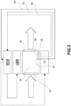
- the purification and microbiological sanitization system 10 essentially comprises a casing 14, a plurality of light-emitting diodes LED, an ionizer device 16, an electronic control unit ECU, and an air quality sensor 18.
- the casing 14 is made as a hollow body, preferably with a tubular structure or a duct, substantially in the form of a frame, or a housing.
- the casing 14 is made of a non-magnetic metallic material, even more preferably of aluminum.
- the casing 14 is made in the form of a rectilinear duct with a quadrangular cross section, but it is not excluded that it may take on different shapes, with a lattice of parallel inner ducts, or in particular that it may comprise a duct of the heating, ventilation, or air conditioning system 12 of the railway vehicle V.
- the casing 14 is adapted to define therein a purification and microbiological sanitization chamber 20 and has an inlet opening 22 adapted to allow the inflow of air into said purification and microbiological sanitization chamber 20 to be sanitized and purified, i.e., decontaminated, and an outlet opening 24 adapted to allow the outflow of sanitized and purified, i.e., decontaminated, air from said purification and microbiological sanitization chamber 20.
- An air flow to be sanitized and purified, i.e., decontaminated, is made to flow inside the casing 14, in a manner known per se, according to the flow direction indicated by the blank arrows in Fig. 3 .
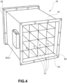
- the purification and microbiological sanitization chamber 20 is internally coated at least partially with a material reflecting UV-C ultraviolet radiation, such as, for example, Teflon.
- the purification and microbiological sanitization chamber 20 is internally divided into a plurality of ducts 21, as shown in Fig. 4 .
- the ducts 21 are arranged side by side and are preferably also made with a quadrangular cross section.
- each of these ducts 21 is coated with a material reflecting UV-C ultraviolet radiation, such as, for example, aluminum and/or polytetrafluoroethylene.
- a material reflecting UV-C ultraviolet radiation such as, for example, aluminum and/or polytetrafluoroethylene.
- At least one filter 26 may be arranged at the inlet opening 22 so as to carry out a first mechanical filtering of the air entering the purification and microbiological sanitization chamber 20.
- this filter 26 may be classified as category G4 according to regulatory standard EN 779:2012.
- the light-emitting diodes LED are adapted to generate a germicidal ultraviolet radiation and to emit it within the purification and microbiological sanitization chamber 20 of the casing 14.
- This germicidal ultraviolet radiation has a wavelength between 100 and 300 nanometers, preferably between about 255 nanometers and about 300 nanometers.
- the ultraviolet radiation of the UV-C type has a particular germicidal efficacy, that is, it is suitable for killing or inactivating any microbiological pathogens present in the air, since these wavelengths have the greatest absorption by nucleic acids: the absorption by nucleic acids of this radiation may cause genetic defects, including the formation of pyrimidine dimers, which may prevent the replication of the nucleic acid and the expression of the proteins necessary for the life cycle of the microorganism, resulting in direct death or inactivation of the microorganism.
- the purification and microbiological sanitization system 10 may comprise a certain number of light-emitting diodes LED; in the example shown, there are four panels each comprising a plurality of light-emitting diodes LED (up to 144 light-emitting diodes LED in total) emitting germicidal ultraviolet radiation, the four panels being respectively arranged on four internal walls of the casing 14, inside the purification and microbiological sanitization chamber 20.
- the presence of a plurality of light-emitting diodes LED allows the appropriate germicidal efficacy to be maintained even in the event of failure of one thereof, ensuring the necessary redundancy.
- the arrangement of the same light-emitting diodes LED, possibly grouped into modules, is obtained in such a way as to maximize the reflective effect of the germicidal ultraviolet radiation UV-C emitted thereby and thus to maximize the radiant power that reaches the inner volume of the purification and microbiological sanitization chamber 20.
- the arrangement of light-emitting diodes LED is such as to ensure that the emitted radiation reaches for the most part the purification and microbiological sanitization chamber 20 and is not dispersed inside the coach C of the railway vehicle V, where it could be a source of danger for the crew or passengers.
- At least one respective light-emitting diode LED of said plurality of light-emitting diodes LED is arranged inside each duct 21.
- more than one light-emitting diode LED is disposed within each duct 21.
- at least one light-emitting diode LED is arranged at a mid-section of the respective duct 21, that is, it is arranged at approximately half the length of the duct 21.
- the light-emitting diodes LED of said plurality of light-emitting diodes LED are connected in series with each other.
- the ionizer device 16 is adapted to at least partially ionize the air contained inside the purification and microbiological sanitization chamber 20 of the casing 14 and is arranged accordingly.
- the ionizer device 16 produces negative ions, which aid in the removal of gases, aerosols, allergens, and polluting particles. In effect, these negative ions bind to the particles present in the air and dispersed therein, such as dust, particulate matter, pathogens (or fragments thereof following exposure to germicidal ultraviolet radiation), and pollen, causing them to deposit on inner surfaces of the casing 14.
- the ionizer device 16 is adapted to ionize, through at least partial reduction, the ionizable compounds (dust, pollen, etc.) present in the air contained within said purification and microbiological sanitization chamber 20 of the casing 14.
- the ionizer device 16 is adapted to ensure the generation of about 2000-4000 ions/cm 3 , so as to obtain an optimal balance between air purification and energy demand.
- the ionizer device 16 further generates a small fraction of ozone (about 0.1 ppm).
- the ionizer device 16 is arranged within the purification and microbiological sanitization chamber 20, but nothing prevents its arrangement from being different, as long as it is possible to ensure partial but sufficient ionization of the air contained in the purification and microbiological sanitization chamber 20.
- the arrangement of the ionizer device 16 is such as to ensure that the ionized air is for the most part contained in the purification and microbiological sanitization chamber 20 and not present inside the coach C of the railway vehicle V, where it could be a source of danger for the crew or passengers.
- the purification and microbiological sanitization system 10 may also comprise a greater number of ionizer devices 16, without thereby departing from the scope of the invention.
- the ionizer device 16, the filter 26, and the plurality of ducts 21 are arranged in such a way that, during operation, the air introduced into the purification and microbiological sanitization chamber 20 passes in sequence through the ionizer device 16, the filter 26, and then the plurality of ducts 21.
- the filter 26 is made as a plate element, i.e., it comprises a partially permeable wall through which the air flow is made to pass, and which carries out the filtering and is irradiated by at least one respective light-emitting diode LED of said plurality of light-emitting diodes LED on each surface of said wall.
- All components of the purification and microbiological sanitization system 10 that require electrical power to operate including the light-emitting diodes LED, the ionizer device 16, and the electronic control unit ECU, are preferably powered by connection to the electrical power supplied to said railway vehicle V by an auxiliary voltage supply line, in turn supplied by a voltage line L through a conventional pantograph P.
- auxiliary voltage supply line in turn supplied by a voltage line L through a conventional pantograph P.
- the air quality sensor 18 is adapted to measure a concentration of particulate matter, an ozone concentration, and a concentration of carbon dioxide in the air at said outlet opening 24, to generate a respective measurement signal Sp representative of said measurements, and to transmit it by means of data transmission (known per se, not shown) to the electronic control unit ECU.
- data transmission means may alternatively be wired or wireless.
- the air quality sensor 18 comprises a multichannel optical sensor, which allows the continuous and simultaneous determination of the total particulate matter, the PM10 particulate fraction, the PM4 particulate fraction, the 2.5 particulate fraction, and the PM1 particulate fraction, or at least two of the above, in addition to measuring the concentration of carbon dioxide and of ozone.
- the purification and microbiological sanitization system 10 further comprises at least one environmental sensor 28 adapted to measure at least one of either the temperature or humidity of the air within said purification and microbiological sanitization chamber 20, to generate a respective measurement signal Se representative of such measurement and to transmit it to said electronic control unit ECU.
- at least one environmental sensor 28 adapted to measure at least one of either the temperature or humidity of the air within said purification and microbiological sanitization chamber 20, to generate a respective measurement signal Se representative of such measurement and to transmit it to said electronic control unit ECU.
- the environmental sensor 28 may also be adapted to detect further parameters, such as the air pressure, or the concentration of other components, such as for example volatile organic components, or any other polluting components.
- the purification and microbiological sanitization system 10 further comprises at least one anemometer 30 adapted to measure the air velocity within said purification and microbiological sanitization chamber 20, preferably at or near said outlet opening 24 of the casing 14, to generate a respective measurement signal Sv representative of said measurement, and to transmit it to said electronic control unit ECU.
- at least one anemometer 30 adapted to measure the air velocity within said purification and microbiological sanitization chamber 20, preferably at or near said outlet opening 24 of the casing 14, to generate a respective measurement signal Sv representative of said measurement, and to transmit it to said electronic control unit ECU.
- the air quality sensor 18, the environmental sensor 28, and the anemometer 30 are made (all or at least two thereof) integrally in a single measurement component.
- a wire mesh filtering device 32 which is heated by means of a dedicated heater, preferably electrically powered, and even more preferably with recovery of the waste heat energy of the light-emitting diodes LED, and which is adapted to heat the air contained or passing through the purification and microbiological sanitization chamber 20, preferably up to a maximum temperature of about 55-65°C, only near the grid of the wire mesh.
- this wire mesh filtering device is provided in the form of a resistance wire mesh and is arranged in such a way as to be in contact with metal heat sinks associated with the light-emitting diodes LED to recover the heat thereby dissipated.
- the purification and microbiological sanitization system 10 further comprises the electronic control unit ECU.
- Said electronic control unit ECU is configured, or programmed, to control the purification and microbiological sanitization system 10, or at least one of the components that comprise it.
- the electronic control unit ECU is configured to control the radiant power of at least one light-emitting diode LED as a function of the measurement signal Sp received from the air quality sensor 18.
- the electronic control unit ECU carries out the aforesaid control of the purification and microbiological sanitization system 10, or of at least one of the components that comprise it, by controlling the frequency of the supply current (PWM signal).
- the electronic control unit ECU is configured to control the radiant power of at least one light-emitting diode LED as a function of the result of a comparison between the measurement signal Sp transmitted by the air quality sensor 18 and a control value stored in the electronic control unit ECU.
- the control value may thus be a programmed target value, whereby, for example, the radiant power of at least one light-emitting diode LED is increased if the target value has not been reached, and therefore the measurement signal Sp sent by the air quality sensor 18 is indicative that a concentration of particulate matter or a concentration of carbon dioxide is still higher than the target value.
- the electronic control unit ECU determines that the measurement signal Sp sent by the air quality sensor 18 is indicative of a concentration of particulate matter or a concentration of carbon dioxide sufficiently below the target value, then, preferably, the electronic control unit ECU may be configured to command a reduction in the radiant power emitted by at least one light-emitting diode LED in order to always ensure the minimum use of electrical power, and therefore improve the energy efficiency of the purification and microbiological sanitization system 10 as a whole.
- the electronic control unit ECU may also be configured to control an electrical power supply to the ionizer device 16 as a function of the measurement signal Sp transmitted by the air quality sensor 18.
- the electronic control unit ECU may also be configured to control the radiant power of at least one light-emitting diode LED and/or the electric power supply to the ionizer device 16 also as a function of the measurement signal Se transmitted from the environmental sensor 28, when present.
- the electronic control unit ECU may also be configured to control the radiant power of at least one light-emitting diode LED and/or to control the electrical power supply to the ionizer device 16 also as a function of the measurement signal Sv transmitted by said anemometer 30, when present.
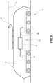
- the purification and microbiological sanitization system 10 is adapted to be applied to the heating, ventilation, or air conditioning system 12 of a railway vehicle V, or of a single coach C of said railway vehicle V, as shown in Fig. 2 .
- the system 12 comprises, in addition to the purification and microbiological sanitization system 10 according to the invention, an inflow duct 34 and an outflow duct 36.
- the inflow duct 34 and the outflow duct 36 are made as conventional ducts of a ventilation, heating, or air conditioning system and therefore are not described in further detail.
- the inflow duct 34 in any case, is adapted to take in air to be sanitized and purified, or decontaminated, from the coach C of the railway vehicle V and conduct it to said purification and microbiological sanitization system 10, to introduce it into the purification and microbiological sanitization chamber 20 of the purification and microbiological sanitization system 10 through the inlet opening 22.
- the outflow duct 36 is adapted to reintroduce the sanitized and purified, or decontaminated, air coming from the purification and microbiological sanitization system 10 into the coach C of the railway vehicle V.
- the heating, ventilation, or air conditioning system 10 may comprise additional ventilation, heating, or air conditioning elements, which may be arranged both upstream and downstream of the purification and microbiological sanitization system 10.
- the arrangement or position of the component elements of the purification and microbiological sanitization system 10 may be modified without thereby departing from the scope of the invention as defined in the appended claims. It is possible, for example, to arrange, alternatively, the ionizer device 16 downstream or upstream of the filter 26, and, similarly, to arrange the light-emitting diodes LED downstream from, coinciding with, or upstream of the ionizer device 16, it being understood that that which is shown in the figures and described in this description constitutes one or some of the embodiments of the invention falling under the scope of the appended claims.
Landscapes
- Engineering & Computer Science (AREA)
- Mechanical Engineering (AREA)
- Health & Medical Sciences (AREA)
- Epidemiology (AREA)
- Animal Behavior & Ethology (AREA)
- Physics & Mathematics (AREA)
- Thermal Sciences (AREA)
- Combustion & Propulsion (AREA)
- Chemical & Material Sciences (AREA)
- Life Sciences & Earth Sciences (AREA)
- General Engineering & Computer Science (AREA)
- General Health & Medical Sciences (AREA)
- Public Health (AREA)
- Veterinary Medicine (AREA)
- Disinfection, Sterilisation Or Deodorisation Of Air (AREA)
- Air-Conditioning For Vehicles (AREA)
- Treating Waste Gases (AREA)
- Vehicle Waterproofing, Decoration, And Sanitation Devices (AREA)
Claims (13)
- Luftreinigungs- und mikrobiologisches Desinfektionssystem (10) für ein Heizungs-, Belüftungs- oder Klimatisierungssystem (12) eines Schienenfahrzeugs (V) oder dergleichen, wobei das Reinigungs- und mikrobiologische Desinfektionssystem (10) aufweist:ein Gehäuse (14), das dazu ausgelegt ist, eine Reinigungs- und mikrobiologische Desinfektionskammer (20) darin zu definieren, und das eine Einlassöffnung (22) aufweist, die dazu ausgestaltet ist, das Einströmen von Luft in die Reinigungs- und mikrobiologische Desinfektionskammer (20) zu ermöglichen, sowie eine Auslassöffnung (24), die dazu ausgestaltet ist, das Ausströmen von Luft aus der Reinigungs- und mikrobiologischen Desinfektionskammer (20) zu ermöglichen;eine Ionisierungsvorrichtung (16), die dazu ausgestaltet ist, die innerhalb der Reinigungs- und mikrobiologischen Desinfektionskammer (20) des Gehäuses (14) enthaltene Luft zumindest teilweise zu ionisieren;eine elektronische Steuereinheit (ECU), die dazu ausgelegt ist, das Luftreinigungs- und mikrobiologische Desinfektionssystem (10) zu steuern; undeinen Luftqualitätssensor (18), der dazu ausgestaltet ist, eine Partikelkonzentration und eine Kohlendioxidkonzentration in der Luft bei der Auslassöffnung (24) zu messen, ein entsprechendes Messsignal (Sp), das für die Messungen repräsentativ ist, zu erzeugen und es an die elektronische Steuereinheit (ECU) zu übermitteln,dadurch gekennzeichnet, dass es weiterhineine Mehrzahl von lichtemittierenden Dioden (LED) aufweist, die jeweils dazu ausgestaltet sind, eine keimtötende ultraviolette Strahlung mit einer Wellenlänge zwischen 100 und 300 nm zu erzeugen und diese Strahlung ins Innere der Reinigungs- und mikrobiologischen Desinfektionskammer (20) des Gehäuses (14) zu emittieren;wobei die elektronische Steuereinheit (ECU) dazu ausgelegt ist, die Strahlungsleistung zumindest einer lichtemittierenden Diode (LED) in Abhängigkeit von dem von dem Luftqualitätssensor (18) übermittelten Messsignal (Sp) zu steuern,wobei die Reinigungs- und mikrobiologische Desinfektionskammer (20) in eine Mehrzahl von Seite an Seite angeordneten Kanälen (21) unterteilt ist, undwobei mindestens eine der jeweiligen lichtemittierenden Dioden (LED) der Mehrzahl von lichtemittierenden Dioden (LED) innerhalb jedes der Kanäle (21) angeordnet ist.
- Reinigungs- und mikrobiologisches Desinfektionssystem nach Anspruch 1, wobei die lichtemittierenden Dioden (LEDs) der Mehrzahl von lichtemittierenden Dioden (LEDs) miteinander in Reihe geschaltet sind.
- Reinigungs- und mikrobiologisches Desinfektionssystem nach Anspruch 1 oder Anspruch 2, wobei die mindestens eine der jeweiligen innerhalb jedes der Kanäle (21) angeordneten lichtemittierenden Dioden (LED) in einem Mittelbereich des jeweiligen Kanals (21) angeordnet ist.
- Reinigungs- und mikrobiologisches Desinfektionssystem nach einem der vorangehenden Ansprüche, wobei die elektronische Steuereinheit (ECU) dazu ausgelegt ist, die Strahlungsleistung mindestens einer lichtemittierenden Diode (LED) in Abhängigkeit von dem Ergebnis eines Vergleichs zwischen dem von dem Luftqualitätssensor (18) übermittelten Messsignal (Sp) und einem in der elektronischen Steuereinheit (ECU) gespeicherten Kontrollwert zu steuern.
- Reinigungs- und mikrobiologisches Desinfektionssystem nach Anspruch [Angabe fehlt; Anmerkung des Übersetzers] oder Anspruch 4, wobei der Luftqualitätssensor (18) dazu ausgestaltet ist, gleichzeitig oder kontinuierlich die Kohlendioxidkonzentration, die Ozonkonzentration und die Konzentration zumindest zweier Partikel aus den Gesamtpartikeln, der Partikelfraktion PM10, der Partikelfraktion PM4, der Partikelfraktion PM2,5 und der Partikelfraktion PM1 zu messen.
- Reinigungs- und mikrobiologisches Desinfektionssystem nach einem der vorangehenden Ansprüche, wobei die Innenfläche jedes Kanals (21) der Mehrzahl von Kanälen (21) der Reinigungs- und mikrobiologischen Desinfektionskammer (20) mit einem ultraviolette Strahlung reflektierenden Material UV-C, bevorzugt Aluminium und/oder Polytetrafluorethylen, beschichtet ist.
- Reinigungs- und mikrobiologisches Desinfektionssystem nach einem der vorangehenden Ansprüche, wobei die elektronische Steuereinheit (ECU) weiter dazu ausgelegt ist, eine elektrische Energieversorgung an die Ionisierungsvorrichtung (16) in Abhängigkeit von dem von dem Luftqualitätssensor (18) übermittelten Messsignal (Sp) zu steuern.
- Reinigungs- und mikrobiologisches Desinfektionssystem nach einem der vorangehenden Ansprüche, weiter aufweisend einen Umgebungssensor (28), der dazu ausgestaltet ist, mindestens eines von entweder der Temperatur oder der Feuchtigkeit der Luft innerhalb der Reinigungs- und mikrobiologischen Desinfektionskammer (20) zu messen, ein entsprechendes Messsignal (Sp), das für die Messungen repräsentativ ist, zu erzeugen und es an die elektronische Steuereinheit (ECU) zu übermitteln, wobei die elektronische Steuereinheit (ECU) weiter dazu ausgelegt ist, die Strahlungsleistung der mindestens einen lichtemittierenden Diode (LED) zu steuern und/oder eine elektrische Energieversorgung an die Ionisierungsvorrichtung (16) auch in Abhängigkeit von dem von dem Umgebungssensor (28) übermittelten Messsignal (Sp) zu steuern.
- Reinigungs- und mikrobiologisches Desinfektionssystem nach einem der vorangehenden Ansprüche, weiter aufweisend ein Anemometer (30), das dazu ausgestaltet ist, die Luftgeschwindigkeit innerhalb der Reinigungs- und mikrobiologischen Desinfektionskammer (20) zu messen, ein entsprechendes Messsignal (Sp), das für die Messungen repräsentativ ist, zu erzeugen und es an die elektronische Steuereinheit (ECU) zu übermitteln, wobei die elektronische Steuereinheit (ECU) weiter dazu ausgelegt ist, die Strahlungsleistung der mindestens einen lichtemittierenden Diode (LED) zu steuern und/oder eine elektrische Energieversorgung an die Ionisierungsvorrichtung (16) auch in Abhängigkeit von dem von dem Anemometer (30) übermittelten Messsignal (Sp) zu steuern.
- Reinigungs- und mikrobiologisches Desinfektionssystem nach einem der vorangehenden Ansprüche, weiter aufweisend eine Filtervorrichtung (32) mit einem Drahtgeflecht, die innerhalb der Reinigungs- und mikrobiologischen Desinfektionskammer (20) angeordnet ist und dazu ausgestaltet ist, die darin enthaltene Luft zu erwärmen.
- Reinigungs- und mikrobiologisches Desinfektionssystem nach einem der vorangehenden Ansprüche, weiter aufweisend einen Filter der Klasse G4 (26) gemäß dem europäischen Standard EN 779:201, der vorzugsweise an der Einlassöffnung (22) des Gehäuses (14) angeordnet und dazu ausgestaltet ist, in die Reinigungs- und mikrobiologischen Desinfektionskammer (20) einströmende Luft zu filtern.
- Reinigungs- und mikrobiologisches Desinfektionssystem nach Anspruch 11, wobei die Ionisierungsvorrichtung (16), der Filter (26) und die Mehrzahl von Kanälen (21) derart angeordnet sind, dass im Betrieb die in die Reinigungs- und mikrobiologische Desinfektionskammer (20) eingeführte Luft nacheinander die Ionisierungsvorrichtung (16), den Filter (26) und die Mehrzahl von Kanälen (21) passiert.
- Heizungs-, Belüftungs- oder Klimatisierungssystem (12) eines Schienenfahrzeugs (V), aufweisend:ein Reinigungs- und mikrobiologisches Desinfektionssystem (10) nach einem der vorangehenden Ansprüche;einen Luftzuführkanal (34), der dazu ausgestaltet ist, zu desinfizierende und zu reinigende Luft von einem Wagen (C) des Schienenfahrzeugs (V) einzuziehen und sie dem Reinigungs- und mikrobiologisches Desinfektionssystem (10) zuzuleiten, um sie mittels der Einlassöffnung (22) in die Reinigungs- und mikrobiologische Desinfektionskammer (20) des Reinigungs- und mikrobiologischen Desinfektionssystem (10) einzuleiten; undeinen Luftableitkanal (36), der dazu ausgestaltet ist, desinfizierte und gereinigte aus dem Reinigungs- und mikrobiologischen Desinfektionssystem (10) kommende Luft wieder in das Innere des Wagens (C) des Schienenfahrzeugs (V) einzuleiten.
Applications Claiming Priority (2)
| Application Number | Priority Date | Filing Date | Title |
|---|---|---|---|
| IT102020000011512A IT202000011512A1 (it) | 2020-05-19 | 2020-05-19 | Sistema di sanificazione microbiologica e purificazione dell'aria per impianto hvac di veicolo ferroviario |
| PCT/IB2021/054194 WO2021234529A1 (en) | 2020-05-19 | 2021-05-17 | Microbiological sanitization and air purification system for hvac system of a railway vehicle |
Publications (2)
| Publication Number | Publication Date |
|---|---|
| EP3972861A1 EP3972861A1 (de) | 2022-03-30 |
| EP3972861B1 true EP3972861B1 (de) | 2023-05-03 |
Family
ID=72266614
Family Applications (1)
| Application Number | Title | Priority Date | Filing Date |
|---|---|---|---|
| EP21727937.1A Active EP3972861B1 (de) | 2020-05-19 | 2021-05-17 | Mikrobiologisches hygienisierungs- und luftreinigungssystem für hlk-system eines schienenfahrzeuges |
Country Status (6)
| Country | Link |
|---|---|
| US (1) | US20220268458A1 (de) |
| EP (1) | EP3972861B1 (de) |
| ES (1) | ES2945870T3 (de) |
| IT (1) | IT202000011512A1 (de) |
| WO (2) | WO2021234439A1 (de) |
| ZA (1) | ZA202300819B (de) |
Families Citing this family (3)
| Publication number | Priority date | Publication date | Assignee | Title |
|---|---|---|---|---|
| EP3912649B1 (de) * | 2020-05-19 | 2023-10-25 | SEIWO Technik GmbH | Modularer schutzraum sowie durchreiche für einen schutzraum |
| US11931472B1 (en) * | 2020-12-18 | 2024-03-19 | Zoox, Inc. | Vehicle with UVC light emitters |
| US20220378973A1 (en) * | 2021-05-25 | 2022-12-01 | Bor-Jen Wu | UVC LED Disinfecting Device |
Family Cites Families (14)
| Publication number | Priority date | Publication date | Assignee | Title |
|---|---|---|---|---|
| CH679278A5 (en) * | 1990-04-30 | 1992-01-31 | Nu Aire Ag | Removing odours from enclosed spaces e.g. cars - by circulating air through ozone-prodn. unit for specified time then ventilating space with fresh air |
| JP2000071758A (ja) * | 1998-08-28 | 2000-03-07 | Zexel Corp | 陰イオン発生機能を備えた車両用空調装置 |
| US6116095A (en) * | 1998-11-09 | 2000-09-12 | White Consolidated Industries, Inc. | Apparatus and method for measuring air flow from a duct system |
| US6716406B2 (en) * | 2001-07-30 | 2004-04-06 | Carrier Corporation | Control system for a photocatalytic air purifier |
| US6787782B1 (en) * | 2003-04-23 | 2004-09-07 | B/E Aerospace, Inc. | Ultraviolet-light vehicle air cleaning system |
| US20050031503A1 (en) * | 2003-08-05 | 2005-02-10 | Fox Michael T. | Air ionization control |
| FI20065227A7 (fi) * | 2006-04-10 | 2007-10-11 | Raimo Vartiainen | Menetelmä ja laitteisto ilman puhdistamiseksi |
| JP2011105257A (ja) * | 2009-11-20 | 2011-06-02 | Sanden Corp | 車両用空調装置 |
| CN202086832U (zh) * | 2011-05-24 | 2011-12-28 | 深圳市百欧森环保科技开发有限公司 | 轨道车厢专用的光等离子空气净化装置 |
| JP5461736B1 (ja) * | 2013-05-13 | 2014-04-02 | 株式会社 片野工業 | イオン・オゾン風発生装置及び方法 |
| KR101588833B1 (ko) * | 2014-08-28 | 2016-01-26 | 엘지전자 주식회사 | 차량용 공기청정기 |
| CN104986014B (zh) * | 2015-07-06 | 2017-01-04 | 江苏埃萨云派环境科技有限公司 | 车载高能离子空气净化装置 |
| KR101867066B1 (ko) * | 2016-07-20 | 2018-06-12 | (주)엠큐더블유 | 차량용 공기청정기 |
| CN107351651A (zh) * | 2017-07-18 | 2017-11-17 | 合肥康居人智能科技有限公司 | 基于avr的多功能车载制氧机净化系统 |
-
2020
- 2020-05-19 IT IT102020000011512A patent/IT202000011512A1/it unknown
- 2020-08-21 WO PCT/IB2020/057850 patent/WO2021234439A1/en not_active Ceased
-
2021
- 2021-05-17 US US17/623,015 patent/US20220268458A1/en active Pending
- 2021-05-17 WO PCT/IB2021/054194 patent/WO2021234529A1/en not_active Ceased
- 2021-05-17 ES ES21727937T patent/ES2945870T3/es active Active
- 2021-05-17 EP EP21727937.1A patent/EP3972861B1/de active Active
-
2023
- 2023-01-18 ZA ZA2023/00819A patent/ZA202300819B/en unknown
Also Published As
| Publication number | Publication date |
|---|---|
| WO2021234439A1 (en) | 2021-11-25 |
| EP3972861A1 (de) | 2022-03-30 |
| IT202000011512A1 (it) | 2021-11-19 |
| US20220268458A1 (en) | 2022-08-25 |
| ZA202300819B (en) | 2023-09-27 |
| WO2021234529A1 (en) | 2021-11-25 |
| ES2945870T3 (es) | 2023-07-10 |
Similar Documents
| Publication | Publication Date | Title |
|---|---|---|
| EP3972861B1 (de) | Mikrobiologisches hygienisierungs- und luftreinigungssystem für hlk-system eines schienenfahrzeuges | |
| US7473304B2 (en) | Air filtration device for closed environments | |
| CN102933281B (zh) | 空气过滤装置 | |
| EP1556093A2 (de) | Luftreinigung | |
| US12268799B2 (en) | Device containing air detection, filtering, disinfecting and conditioning elements with display | |
| KR102455712B1 (ko) | 에어컨의 필터 살균 장치 | |
| KR102385525B1 (ko) | 철도 차량용 객실 공기 살균 시스템 | |
| US11760171B2 (en) | Three stage air purification for rail vehicles | |
| KR20200035618A (ko) | 공조필터시스템 | |
| KR101353581B1 (ko) | 자외선 발광 다이오드를 이용한 유체 정화 장치 | |
| US20220144038A1 (en) | Systems and methods useful for air treatment in a vehicle | |
| JP7188704B2 (ja) | 空調ダクト用空気清浄機 | |
| Mathur | Energy Consumption of Titanium Dioxide & Ultraviolet Germicidal (UV-C) Photocatalytic Air Purification System for Automotive Cabins | |
| CN214647478U (zh) | 空气过滤组件和车辆的车舱空气通风系统 | |
| US20060005705A1 (en) | Electro-optical air sterilizer with ionizer | |
| US20220001071A1 (en) | Sanitizing systems and methods for commercial passenger vehicles | |
| FI119679B (fi) | Menetelmä ja laitteisto kaasun steriloimiseksi | |
| JP4113345B2 (ja) | 殺菌フィルタユニットおよび空気清浄システム | |
| CN111359330A (zh) | 对汽车空调排放至车内的空气杀菌净化的方法及滤芯组件 | |
| EP3904211B1 (de) | Integration von uv-licht in flugzeugluftmanagementsysteme | |
| CN214564504U (zh) | 空气过滤组件和车辆的车舱空气通风系统 | |
| Mathur | UV-LEDs Based Photocatalytic Cabin IAQ System to Eliminate Viruses Encountered in a Conditioned Space | |
| KR102726860B1 (ko) | 휴대용 플라즈마 발생장치 | |
| KR20210116076A (ko) | 실내용 식생부를 구비한 공기정화장치 | |
| CN219056244U (zh) | 一种净化组件及净化设备 |
Legal Events
| Date | Code | Title | Description |
|---|---|---|---|
| STAA | Information on the status of an ep patent application or granted ep patent |
Free format text: STATUS: UNKNOWN |
|
| STAA | Information on the status of an ep patent application or granted ep patent |
Free format text: STATUS: THE INTERNATIONAL PUBLICATION HAS BEEN MADE |
|
| PUAI | Public reference made under article 153(3) epc to a published international application that has entered the european phase |
Free format text: ORIGINAL CODE: 0009012 |
|
| STAA | Information on the status of an ep patent application or granted ep patent |
Free format text: STATUS: REQUEST FOR EXAMINATION WAS MADE |
|
| 17P | Request for examination filed |
Effective date: 20211224 |
|
| AK | Designated contracting states |
Kind code of ref document: A1 Designated state(s): AL AT BE BG CH CY CZ DE DK EE ES FI FR GB GR HR HU IE IS IT LI LT LU LV MC MK MT NL NO PL PT RO RS SE SI SK SM TR |
|
| GRAP | Despatch of communication of intention to grant a patent |
Free format text: ORIGINAL CODE: EPIDOSNIGR1 |
|
| STAA | Information on the status of an ep patent application or granted ep patent |
Free format text: STATUS: GRANT OF PATENT IS INTENDED |
|
| RAP1 | Party data changed (applicant data changed or rights of an application transferred) |
Owner name: STE-SANITIZING TECHNOLOGIES AND EQUIPMENTS S.R.L. |
|
| DAX | Request for extension of the european patent (deleted) | ||
| RAV | Requested validation state of the european patent: fee paid |
Extension state: TN Effective date: 20211224 Extension state: MA Effective date: 20211224 |
|
| INTG | Intention to grant announced |
Effective date: 20221123 |
|
| GRAS | Grant fee paid |
Free format text: ORIGINAL CODE: EPIDOSNIGR3 |
|
| GRAA | (expected) grant |
Free format text: ORIGINAL CODE: 0009210 |
|
| STAA | Information on the status of an ep patent application or granted ep patent |
Free format text: STATUS: THE PATENT HAS BEEN GRANTED |
|
| AK | Designated contracting states |
Kind code of ref document: B1 Designated state(s): AL AT BE BG CH CY CZ DE DK EE ES FI FR GB GR HR HU IE IS IT LI LT LU LV MC MK MT NL NO PL PT RO RS SE SI SK SM TR |
|
| REG | Reference to a national code |
Ref country code: GB Ref legal event code: FG4D |
|
| REG | Reference to a national code |
Ref country code: DE Ref legal event code: R096 Ref document number: 602021002196 Country of ref document: DE |
|
| REG | Reference to a national code |
Ref country code: AT Ref legal event code: REF Ref document number: 1564296 Country of ref document: AT Kind code of ref document: T Effective date: 20230515 Ref country code: CH Ref legal event code: EP |
|
| REG | Reference to a national code |
Ref country code: IE Ref legal event code: FG4D |
|
| REG | Reference to a national code |
Ref country code: ES Ref legal event code: FG2A Ref document number: 2945870 Country of ref document: ES Kind code of ref document: T3 Effective date: 20230710 |
|
| REG | Reference to a national code |
Ref country code: LT Ref legal event code: MG9D |
|
| REG | Reference to a national code |
Ref country code: NL Ref legal event code: MP Effective date: 20230503 |
|
| REG | Reference to a national code |
Ref country code: AT Ref legal event code: MK05 Ref document number: 1564296 Country of ref document: AT Kind code of ref document: T Effective date: 20230503 |
|
| PG25 | Lapsed in a contracting state [announced via postgrant information from national office to epo] |
Ref country code: SE Free format text: LAPSE BECAUSE OF FAILURE TO SUBMIT A TRANSLATION OF THE DESCRIPTION OR TO PAY THE FEE WITHIN THE PRESCRIBED TIME-LIMIT Effective date: 20230503 Ref country code: PT Free format text: LAPSE BECAUSE OF FAILURE TO SUBMIT A TRANSLATION OF THE DESCRIPTION OR TO PAY THE FEE WITHIN THE PRESCRIBED TIME-LIMIT Effective date: 20230904 Ref country code: NO Free format text: LAPSE BECAUSE OF FAILURE TO SUBMIT A TRANSLATION OF THE DESCRIPTION OR TO PAY THE FEE WITHIN THE PRESCRIBED TIME-LIMIT Effective date: 20230803 Ref country code: NL Free format text: LAPSE BECAUSE OF FAILURE TO SUBMIT A TRANSLATION OF THE DESCRIPTION OR TO PAY THE FEE WITHIN THE PRESCRIBED TIME-LIMIT Effective date: 20230503 Ref country code: AT Free format text: LAPSE BECAUSE OF FAILURE TO SUBMIT A TRANSLATION OF THE DESCRIPTION OR TO PAY THE FEE WITHIN THE PRESCRIBED TIME-LIMIT Effective date: 20230503 |
|
| PG25 | Lapsed in a contracting state [announced via postgrant information from national office to epo] |
Ref country code: RS Free format text: LAPSE BECAUSE OF FAILURE TO SUBMIT A TRANSLATION OF THE DESCRIPTION OR TO PAY THE FEE WITHIN THE PRESCRIBED TIME-LIMIT Effective date: 20230503 Ref country code: PL Free format text: LAPSE BECAUSE OF FAILURE TO SUBMIT A TRANSLATION OF THE DESCRIPTION OR TO PAY THE FEE WITHIN THE PRESCRIBED TIME-LIMIT Effective date: 20230503 Ref country code: LV Free format text: LAPSE BECAUSE OF FAILURE TO SUBMIT A TRANSLATION OF THE DESCRIPTION OR TO PAY THE FEE WITHIN THE PRESCRIBED TIME-LIMIT Effective date: 20230503 Ref country code: LT Free format text: LAPSE BECAUSE OF FAILURE TO SUBMIT A TRANSLATION OF THE DESCRIPTION OR TO PAY THE FEE WITHIN THE PRESCRIBED TIME-LIMIT Effective date: 20230503 Ref country code: IS Free format text: LAPSE BECAUSE OF FAILURE TO SUBMIT A TRANSLATION OF THE DESCRIPTION OR TO PAY THE FEE WITHIN THE PRESCRIBED TIME-LIMIT Effective date: 20230903 Ref country code: HR Free format text: LAPSE BECAUSE OF FAILURE TO SUBMIT A TRANSLATION OF THE DESCRIPTION OR TO PAY THE FEE WITHIN THE PRESCRIBED TIME-LIMIT Effective date: 20230503 Ref country code: GR Free format text: LAPSE BECAUSE OF FAILURE TO SUBMIT A TRANSLATION OF THE DESCRIPTION OR TO PAY THE FEE WITHIN THE PRESCRIBED TIME-LIMIT Effective date: 20230804 |
|
| PG25 | Lapsed in a contracting state [announced via postgrant information from national office to epo] |
Ref country code: FI Free format text: LAPSE BECAUSE OF FAILURE TO SUBMIT A TRANSLATION OF THE DESCRIPTION OR TO PAY THE FEE WITHIN THE PRESCRIBED TIME-LIMIT Effective date: 20230503 |
|
| PG25 | Lapsed in a contracting state [announced via postgrant information from national office to epo] |
Ref country code: SK Free format text: LAPSE BECAUSE OF FAILURE TO SUBMIT A TRANSLATION OF THE DESCRIPTION OR TO PAY THE FEE WITHIN THE PRESCRIBED TIME-LIMIT Effective date: 20230503 |
|
| PG25 | Lapsed in a contracting state [announced via postgrant information from national office to epo] |
Ref country code: SM Free format text: LAPSE BECAUSE OF FAILURE TO SUBMIT A TRANSLATION OF THE DESCRIPTION OR TO PAY THE FEE WITHIN THE PRESCRIBED TIME-LIMIT Effective date: 20230503 Ref country code: SK Free format text: LAPSE BECAUSE OF FAILURE TO SUBMIT A TRANSLATION OF THE DESCRIPTION OR TO PAY THE FEE WITHIN THE PRESCRIBED TIME-LIMIT Effective date: 20230503 Ref country code: RO Free format text: LAPSE BECAUSE OF FAILURE TO SUBMIT A TRANSLATION OF THE DESCRIPTION OR TO PAY THE FEE WITHIN THE PRESCRIBED TIME-LIMIT Effective date: 20230503 Ref country code: LU Free format text: LAPSE BECAUSE OF NON-PAYMENT OF DUE FEES Effective date: 20230517 Ref country code: EE Free format text: LAPSE BECAUSE OF FAILURE TO SUBMIT A TRANSLATION OF THE DESCRIPTION OR TO PAY THE FEE WITHIN THE PRESCRIBED TIME-LIMIT Effective date: 20230503 Ref country code: DK Free format text: LAPSE BECAUSE OF FAILURE TO SUBMIT A TRANSLATION OF THE DESCRIPTION OR TO PAY THE FEE WITHIN THE PRESCRIBED TIME-LIMIT Effective date: 20230503 Ref country code: CZ Free format text: LAPSE BECAUSE OF FAILURE TO SUBMIT A TRANSLATION OF THE DESCRIPTION OR TO PAY THE FEE WITHIN THE PRESCRIBED TIME-LIMIT Effective date: 20230503 |
|
| REG | Reference to a national code |
Ref country code: DE Ref legal event code: R097 Ref document number: 602021002196 Country of ref document: DE |
|
| PG25 | Lapsed in a contracting state [announced via postgrant information from national office to epo] |
Ref country code: MC Free format text: LAPSE BECAUSE OF FAILURE TO SUBMIT A TRANSLATION OF THE DESCRIPTION OR TO PAY THE FEE WITHIN THE PRESCRIBED TIME-LIMIT Effective date: 20230503 |
|
| REG | Reference to a national code |
Ref country code: IE Ref legal event code: MM4A |
|
| PG25 | Lapsed in a contracting state [announced via postgrant information from national office to epo] |
Ref country code: MC Free format text: LAPSE BECAUSE OF FAILURE TO SUBMIT A TRANSLATION OF THE DESCRIPTION OR TO PAY THE FEE WITHIN THE PRESCRIBED TIME-LIMIT Effective date: 20230503 |
|
| PLBE | No opposition filed within time limit |
Free format text: ORIGINAL CODE: 0009261 |
|
| STAA | Information on the status of an ep patent application or granted ep patent |
Free format text: STATUS: NO OPPOSITION FILED WITHIN TIME LIMIT |
|
| 26N | No opposition filed |
Effective date: 20240206 |
|
| PG25 | Lapsed in a contracting state [announced via postgrant information from national office to epo] |
Ref country code: IE Free format text: LAPSE BECAUSE OF NON-PAYMENT OF DUE FEES Effective date: 20230517 |
|
| PG25 | Lapsed in a contracting state [announced via postgrant information from national office to epo] |
Ref country code: IE Free format text: LAPSE BECAUSE OF NON-PAYMENT OF DUE FEES Effective date: 20230517 |
|
| PG25 | Lapsed in a contracting state [announced via postgrant information from national office to epo] |
Ref country code: SI Free format text: LAPSE BECAUSE OF FAILURE TO SUBMIT A TRANSLATION OF THE DESCRIPTION OR TO PAY THE FEE WITHIN THE PRESCRIBED TIME-LIMIT Effective date: 20230503 |
|
| PG25 | Lapsed in a contracting state [announced via postgrant information from national office to epo] |
Ref country code: SI Free format text: LAPSE BECAUSE OF FAILURE TO SUBMIT A TRANSLATION OF THE DESCRIPTION OR TO PAY THE FEE WITHIN THE PRESCRIBED TIME-LIMIT Effective date: 20230503 |
|
| PG25 | Lapsed in a contracting state [announced via postgrant information from national office to epo] |
Ref country code: BG Free format text: LAPSE BECAUSE OF FAILURE TO SUBMIT A TRANSLATION OF THE DESCRIPTION OR TO PAY THE FEE WITHIN THE PRESCRIBED TIME-LIMIT Effective date: 20230503 |
|
| PG25 | Lapsed in a contracting state [announced via postgrant information from national office to epo] |
Ref country code: BG Free format text: LAPSE BECAUSE OF FAILURE TO SUBMIT A TRANSLATION OF THE DESCRIPTION OR TO PAY THE FEE WITHIN THE PRESCRIBED TIME-LIMIT Effective date: 20230503 |
|
| PGFP | Annual fee paid to national office [announced via postgrant information from national office to epo] |
Ref country code: DE Payment date: 20250523 Year of fee payment: 5 |
|
| PGFP | Annual fee paid to national office [announced via postgrant information from national office to epo] |
Ref country code: GB Payment date: 20250527 Year of fee payment: 5 Ref country code: ES Payment date: 20250602 Year of fee payment: 5 |
|
| PGFP | Annual fee paid to national office [announced via postgrant information from national office to epo] |
Ref country code: BE Payment date: 20250521 Year of fee payment: 5 Ref country code: IT Payment date: 20250424 Year of fee payment: 5 |
|
| PGFP | Annual fee paid to national office [announced via postgrant information from national office to epo] |
Ref country code: FR Payment date: 20250430 Year of fee payment: 5 |
|
| PGFP | Annual fee paid to national office [announced via postgrant information from national office to epo] |
Ref country code: CH Payment date: 20250601 Year of fee payment: 5 |
|
| PG25 | Lapsed in a contracting state [announced via postgrant information from national office to epo] |
Ref country code: CY Free format text: LAPSE BECAUSE OF FAILURE TO SUBMIT A TRANSLATION OF THE DESCRIPTION OR TO PAY THE FEE WITHIN THE PRESCRIBED TIME-LIMIT; INVALID AB INITIO Effective date: 20210517 |
|
| PG25 | Lapsed in a contracting state [announced via postgrant information from national office to epo] |
Ref country code: HU Free format text: LAPSE BECAUSE OF FAILURE TO SUBMIT A TRANSLATION OF THE DESCRIPTION OR TO PAY THE FEE WITHIN THE PRESCRIBED TIME-LIMIT; INVALID AB INITIO Effective date: 20210517 |
|
| VS25 | Lapsed in a validation state [announced via postgrant information from nat. office to epo] |
Ref country code: MA Free format text: FAILURE TO ELECT DOMICILE IN THE NATIONAL COUNTRY Effective date: 20230804 |
|
| PG25 | Lapsed in a contracting state [announced via postgrant information from national office to epo] |
Ref country code: TR Free format text: LAPSE BECAUSE OF FAILURE TO SUBMIT A TRANSLATION OF THE DESCRIPTION OR TO PAY THE FEE WITHIN THE PRESCRIBED TIME-LIMIT Effective date: 20230503 |
|
| VS25 | Lapsed in a validation state [announced via postgrant information from nat. office to epo] |
Ref country code: MA Free format text: LAPSE BECAUSE OF FAILURE TO SUBMIT A TRANSLATION OF THE DESCRIPTION OR TO PAY THE FEE WITHIN THE PRESCRIBED TIME-LIMIT Effective date: 20230503 |