EP3904211B1 - Integration von uv-licht in flugzeugluftmanagementsysteme - Google Patents
Integration von uv-licht in flugzeugluftmanagementsysteme Download PDFInfo
- Publication number
- EP3904211B1 EP3904211B1 EP21170761.7A EP21170761A EP3904211B1 EP 3904211 B1 EP3904211 B1 EP 3904211B1 EP 21170761 A EP21170761 A EP 21170761A EP 3904211 B1 EP3904211 B1 EP 3904211B1
- Authority
- EP
- European Patent Office
- Prior art keywords
- air
- light source
- duct
- cabin
- management system
- Prior art date
- Legal status (The legal status is an assumption and is not a legal conclusion. Google has not performed a legal analysis and makes no representation as to the accuracy of the status listed.)
- Active
Links
Images


Classifications
-
- A—HUMAN NECESSITIES
- A61—MEDICAL OR VETERINARY SCIENCE; HYGIENE
- A61L—METHODS OR APPARATUS FOR STERILISING MATERIALS OR OBJECTS IN GENERAL; DISINFECTION, STERILISATION OR DEODORISATION OF AIR; CHEMICAL ASPECTS OF BANDAGES, DRESSINGS, ABSORBENT PADS OR SURGICAL ARTICLES; MATERIALS FOR BANDAGES, DRESSINGS, ABSORBENT PADS OR SURGICAL ARTICLES
- A61L9/00—Disinfection, sterilisation or deodorisation of air
- A61L9/16—Disinfection, sterilisation or deodorisation of air using physical phenomena
- A61L9/18—Radiation
- A61L9/20—Ultraviolet radiation
-
- B—PERFORMING OPERATIONS; TRANSPORTING
- B60—VEHICLES IN GENERAL
- B60H—ARRANGEMENTS OF HEATING, COOLING, VENTILATING OR OTHER AIR-TREATING DEVICES SPECIALLY ADAPTED FOR PASSENGER OR GOODS SPACES OF VEHICLES
- B60H3/00—Other air-treating devices
- B60H3/0071—Electrically conditioning the air, e.g. by ionizing
-
- B—PERFORMING OPERATIONS; TRANSPORTING
- B64—AIRCRAFT; AVIATION; COSMONAUTICS
- B64D—EQUIPMENT FOR FITTING IN OR TO AIRCRAFT; FLIGHT SUITS; PARACHUTES; ARRANGEMENT OR MOUNTING OF POWER PLANTS OR PROPULSION TRANSMISSIONS IN AIRCRAFT
- B64D13/00—Arrangements or adaptations of air-treatment apparatus for aircraft crew or passengers, or freight space
- B64D13/06—Arrangements or adaptations of air-treatment apparatus for aircraft crew or passengers, or freight space the air being conditioned
-
- A—HUMAN NECESSITIES
- A61—MEDICAL OR VETERINARY SCIENCE; HYGIENE
- A61L—METHODS OR APPARATUS FOR STERILISING MATERIALS OR OBJECTS IN GENERAL; DISINFECTION, STERILISATION OR DEODORISATION OF AIR; CHEMICAL ASPECTS OF BANDAGES, DRESSINGS, ABSORBENT PADS OR SURGICAL ARTICLES; MATERIALS FOR BANDAGES, DRESSINGS, ABSORBENT PADS OR SURGICAL ARTICLES
- A61L2209/00—Aspects relating to disinfection, sterilisation or deodorisation of air
- A61L2209/10—Apparatus features
- A61L2209/14—Filtering means
-
- A—HUMAN NECESSITIES
- A61—MEDICAL OR VETERINARY SCIENCE; HYGIENE
- A61L—METHODS OR APPARATUS FOR STERILISING MATERIALS OR OBJECTS IN GENERAL; DISINFECTION, STERILISATION OR DEODORISATION OF AIR; CHEMICAL ASPECTS OF BANDAGES, DRESSINGS, ABSORBENT PADS OR SURGICAL ARTICLES; MATERIALS FOR BANDAGES, DRESSINGS, ABSORBENT PADS OR SURGICAL ARTICLES
- A61L2209/00—Aspects relating to disinfection, sterilisation or deodorisation of air
- A61L2209/10—Apparatus features
- A61L2209/16—Connections to a HVAC unit
-
- B—PERFORMING OPERATIONS; TRANSPORTING
- B64—AIRCRAFT; AVIATION; COSMONAUTICS
- B64D—EQUIPMENT FOR FITTING IN OR TO AIRCRAFT; FLIGHT SUITS; PARACHUTES; ARRANGEMENT OR MOUNTING OF POWER PLANTS OR PROPULSION TRANSMISSIONS IN AIRCRAFT
- B64D13/00—Arrangements or adaptations of air-treatment apparatus for aircraft crew or passengers, or freight space
- B64D13/06—Arrangements or adaptations of air-treatment apparatus for aircraft crew or passengers, or freight space the air being conditioned
- B64D2013/0603—Environmental Control Systems
- B64D2013/0651—Environmental Control Systems comprising filters, e.g. dust filters
-
- B—PERFORMING OPERATIONS; TRANSPORTING
- B64—AIRCRAFT; AVIATION; COSMONAUTICS
- B64D—EQUIPMENT FOR FITTING IN OR TO AIRCRAFT; FLIGHT SUITS; PARACHUTES; ARRANGEMENT OR MOUNTING OF POWER PLANTS OR PROPULSION TRANSMISSIONS IN AIRCRAFT
- B64D13/00—Arrangements or adaptations of air-treatment apparatus for aircraft crew or passengers, or freight space
- B64D13/06—Arrangements or adaptations of air-treatment apparatus for aircraft crew or passengers, or freight space the air being conditioned
- B64D2013/0603—Environmental Control Systems
- B64D2013/0688—Environmental Control Systems with means for recirculating cabin air
Definitions
- Embodiments of the disclosure relate to an air management system used to provide air to one or more compartments within a vehicle, and more specifically, to a system for sterilizing a portion of the air management system and the air therein.
- Pressurized aircraft have integrated air management systems to provide a pressurized environment, fresh air transfer, recycling, heating, and air conditioning to maintain a comfortable safe environment for occupants for extended periods.
- Air recycling and replacing stale air requires continuous scrubbing for cleanliness to minimize airborne dust, dirt, odors, viruses, spores, and bacteria.
- This cleaning or scrubbing of the air is typically performed via physical, electrostatic or chemical filtration, such as via a HEPA filter.
- bacteria and dirt can accumulate on the filter, requiring cleaning or replacement of the filters themselves.
- US 2019/009912 A1 according to its abstract describes a method for air conditioning of an aircraft including the steps of obtaining a fresh air for ventilation; exhausting an air from a cabin; obtaining a purified air for recirculation from a part of the air exhausted; obtaining an air for ventilation; supplying the air for ventilation to the cabin; and irradiating an ultraviolet ray emitted from a UV-LED to the purified air for recirculation.
- US 2015/202107 A1 describes an air purification system for operating theaters.
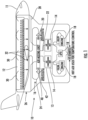
- FIG. 1 a schematic of an example of an air management system 10 to control the air of a vehicle, such as an aircraft 11 is illustrated.
- the aircraft 11 includes a pressurized area or cabin 12 that the air management system 10 controls.
- the cabin 12 may be configured to house people, cargo, and the like therein.
- the air management system 10 provides conditioned air to, and removes used or contaminated air from, the cabin 12.
- the air management system 10 includes an environmental control system 13 having at least one air conditioning unit or pack 14, and a cabin air recirculation sub-system 16. While the air management system 10 is illustrated and described herein with reference to an aircraft 11, it should be understood that, not according to the claims, the systems and techniques discussed herein may be used for a variety of air management systems 10.
- the cabin 12 may be replaced with any closed volume to be conditioned.
- systems described herein may be used with ship air management systems, such as submarines and cruise liners for example, personnel carrier air management systems, bus, trolley, train, or subway air management systems, or any other air management system that requires a continual supply of conditioned air.
- air is provided from one or more sources 18 to the air management system 10.
- suitable sources 18 include but are not limited to an engine of the aircraft 11 and an auxiliary power unit of the aircraft 11.
- the medium output from these sources 18 is provided to the one or more air conditioning units 14 of the environmental control system 13.
- the medium is conditioned. This conditioning includes altering one or more of a pressure, temperature, humidity, or flow rate of the medium based on an operating condition of the aircraft.
- the medium output or discharged from the one or more air conditioning units 14 of the environmental control system 13 may be used maintain a target range of pressures, temperatures, and/or humidity within the cabin 12.
- the medium discharged from the air conditioning units 14 is provided to an air mixing unit or mixing manifold 20 via one or more outlet ducts 22.
- at least one duct 24 of the cabin air recirculation sub-system 16 extends from the cabin 12 to the air mixing unit 20 to deliver air exhausted from the cabin 12 to the air mixing unit 20.
- the cabin recirculating air is mixed with the medium output from the one or more air conditioning units 14 to achieve a mixed medium having one or more desired parameters, such as temperature, pressure, and humidity for example.
- the mixed medium is delivered to the cabin 12 from the air mixing unit 20 via an air distribution system 26 including one or more conduits 28.
- the mixed medium may be delivered to the cabin 12 and cockpit via a ventilation system arranged near a ceiling of the cabin 12.
- the mixed medium typically circulates from the top of the cabin 12 toward the floor, and is distributed to a plurality of individual vents 30 of the ventilation system spaced laterally between the front and rear of the cabin 12.
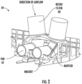
- FIG. 2 an example of a portion of the cabin air recirculation sub-system within the air management system 10 is shown in more detail.
- a portion of the duct 24 of the cabin air recirculation sub-system 16 and fluidly connects one or more outlets 32 (see FIG. 1 ) of the cabin 12 to the air mixing unit 20.
- Mounted within the duct is a filter 40 configured to remove bacteria, viruses and particulate matter from the cabin recirculation air provided from the outlets 32 in the cabin 12 as it flows through the filter 40.
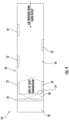
- the filter 40 is shown as being arranged adjacent a downstream end of the duct, such as directly upstream from an interface between the duct and the air mixing unit, a filter arranged at any location within the duct is contemplated herein. Further, although the filter 40 is illustrated as having a circular configuration in FIG. 2 , and a rectangular configuration in FIG. 3 , it should be understood that a filter 40 having any configuration is within the scope of the disclosure. In an embodiment, the filter 40 is a HEPA-type filter. However, any suitable filter, or combination of multiple filters is within the scope of the disclosure.
- the duct 24 includes a recirculation fan 42 to establish an overpressure that is used to drive the flow of the recirculating cabin air through the filter 40 and to the air mixing unit 20.
- a recirculation fan 42 to establish an overpressure that is used to drive the flow of the recirculating cabin air through the filter 40 and to the air mixing unit 20.
- embodiments of a portion of a cabin air recirculation sub-system 16 that do not include a fan such that air flow through the duct 24 is driven by another source or by pressure for example, are also contemplated herein.
- the air management system 10 additionally includes a sterilization system 50 for sterilizing at least a portion of the air therein.
- the sterilization described herein additionally includes killing or rendering harmless bacteria or airborne viruses within the air management system 10 and/or an air flow there through. Because dehumidified air is easier to sterilize, the air is dehumidified before passing through (upstream from) he sterilization system 50 and is then rehumidified downstream of the sterilization system 50, such as in the air mixing unit 20 for example.
- the sterilization system 50 is used to sterilize a portion of the air provided to the cabin 12, such as the cabin recirculation air discharged from outlets 32 of the cabin 12 and provided to the air mixing unit 20 and/or a portion of one or more ducts 24 extending between the cabin outlets 32 and the air mixing unit 20.
- any portion of the air management system 10 and specifically any portion or duct that is used to move cabin discharge air or cabin recirculation air through the air management system 10, including but not limited to the air mixing unit 20 and the conduits 28 of the air distribution system 26 for example, may be adapted for use with a sterilization system 50 as described herein.
- the sterilization system 50 includes at least one light source 52 capable of emitting a light having a wavelength suitable to perform germicidal irradiation.
- the light source 52 is operable to emit a germicidal ultraviolet light, such as having a wavelength between about 200 and about 280 nanometers, also known as "UV-C.”
- the wavelength of the light emitted by the light source 52 may further be between about 220 nm and about 260 nm, or about 240 nm and about 260 nm, about 250nm to about 260nm, or more specifically 253 nm to 254 nm.
- ultraviolet light having another wavelength such as between 280nm and 400nm, and more specifically between 280nm and 315nm, or other types of light may also be suitable for use in sterilization applications.
- a light source 52 having any configuration such as an individual bulb, a light strip having a plurality of bulbs or light emitting diodes, or another type of emitter, is within the scope of the disclosure.
- a configuration of the light sources may be substantially identical, or alternatively, may vary based on a position of the light source 52 relative to the air management system.
- the use of germicidal ultraviolet light, and specifically UV-C light typically requires exposure for only a matter of seconds to kill any virus or bacteria present.
- the length of exposure may vary in response to one or more parameters, such as the wavelength of the light, the intensity or strength of the light, the volume flow rate of air, and the humidity of the air, for example.
- the one or more light sources 52 and an intensity of each light source 52 is determined based on at least one of the volume flow rate and the humidity of the air. Because exposure for only a limited period of time is required for sterilization, the one or more light sources 52 may be disposed at one or more areas along the flow path defined by the duct 24.
- the one or more light sources 52 are located at an area of the flow path where the flow of air provided from the cabin outlets 32 is slowest. For example, the flow rate of the cabin recirculation air through the portion of the duct 24 including the filter 40 is reduced relative to the flow rate of the air at an upstream portion of the duct 24 to maximize the efficacy of the filter 40. Accordingly, in an embodiment, one or more light sources 52 are mounted such that the light emitted therefrom projects over substantially the entire surface 54 of the filter 40. As a result, any viruses or bacteria present on the filter 40, such as trapped in the filter material itself, are killed or neutralized. In such embodiments, the one or more light sources 52 may be integrated into the filter 40 ( FIG.
- the filter 40 may be mounted to a portion of the duct 24, such as directly adjacent the filter 40 ( FIG. 4 ), or alternatively, at a location axially offset from the filter 40 ( FIG. 5 ) such that the light emitted from the light sources 52 overlaps the surface the filter 40.
- the sterilization system 50 may additionally include one or more light sources 52 arranged at a location where the flow rate of the cabin circulation air is faster than at the filter 40. As shown, one or more light sources 52 may be arranged within the air management system 10 to emit germicidal ultraviolet light over a portion of the flow path defined by the duct 24, upstream from the filter 40, as shown in FIGS. 4 and 5 . Although the figures show a sterilization system 50 including a plurality of light sources 52 operable to illuminate substantially the entire length of the duct 24 extending between an upstream end thereof 56 and the filter 40, embodiments where only a portion of the duct 24 is illuminated are also contemplated herein.
- each of the plurality of light sources 52 may be positioned such that the light emitted therefrom overlaps with the light emitted from an adjacent light source 52.
- the light sources may be mounted within the same plane, such as adjacent the same side of the duct 24, or alternatively, at different sides of the duct 24, such as opposite sides ( FIG. 4 ) or adjacent sides ( FIG. 5 ) for example.
- the region of the duct 24 illuminated by the light sources 52 will be free from shadows or non-illuminated areas where bacteria or viruses may accumulate.
- one or more interior surfaces 56 of the duct 24 within the region illuminated by the one or more light sources 52 may have a reflective or mirrored coating to facilitate increased distribution of the germicidal light throughout the duct 24.
- a reflective or mirrored coating as described herein may include, but is not limited to, one or more of aluminum, gold, chrome, nickel, titanium, copper, silver, copper oxide, titanium dioxide, zinc oxide, or another suitable shiny material or polished surface.
- such a coating may be applied via any suitable method, such as via a spray, dip, wipe, vapor deposition, plating, or other known method.
- the coating material is applied via vapor deposition, such as via atomic layer deposition for example. Application of a coating material via atomic layer deposition permits non-line-of-sight coating because a molecular layer of various germicidal chemical compounds may be formed anywhere the vapor makes contact.
- the light sources 52 may be used to continuously disinfect the airflow and/or a portion of a duct 24, without exposing aircraft occupants to any harmful effects from exposure to a high intensity ultra-violet light. Further, the sterilization system could continuously operate when the vehicle is both airborne and grounded without the need for any chemical means of rendering airborne viruses and bacteria harmless. Additionally, the one or more ultra-violet light sources 52 are small, use minimal power, and do not require high power, heat, or chemicals to kill viruses and bacteria.
Landscapes
- Health & Medical Sciences (AREA)
- General Health & Medical Sciences (AREA)
- Engineering & Computer Science (AREA)
- Epidemiology (AREA)
- Life Sciences & Earth Sciences (AREA)
- Animal Behavior & Ethology (AREA)
- Public Health (AREA)
- Veterinary Medicine (AREA)
- Pulmonology (AREA)
- Aviation & Aerospace Engineering (AREA)
- Mechanical Engineering (AREA)
- Disinfection, Sterilisation Or Deodorisation Of Air (AREA)
Claims (9)
- Luftmanagementsystem (10) eines Fahrzeugs, wobei das Fahrzeug ein Luftfahrzeug, umfassend eine Kabine, ist, wobei das Luftmanagementsystem Folgendes umfasst:eine Luftquelle;ein Klimasteuersystem (13) in Fluidverbindung mit der Luftquelle;ein Kabinenluft-Umwälzsystem (16), das zum fluidischen Verbinden mit mindestens einem Auslass der Kabine konfiguriert ist;eine Luftmischeinheit (20), die fluidisch mit dem Klimasteuersystem und dem Kabinenumwälzsystem verbunden ist;ein Luftverteilungssystem (26), das sich von der Luftmischeinheit erstreckt und zum Erstrecken bis zu einer oder mehreren der Kabine zugeordneten Lüftungsöffnungen konfiguriert ist;mindestens einen Kanal (24), der einen Strömungsweg zum Abgeben von Luft an die Kabine definiert und sich zwischen dem mindestens einen Auslass der Kabine und der Luftmischeinheit (20) erstreckt; undein Sterilisationssystem (50), das dem mindestens einen Kanal zugeordnet ist, wobei das Sterilisationssystem mindestens eine Lichtquelle beinhaltet, die zum Abgeben von keimtötendem ultraviolettem Licht in den durch den mindestens einen Kanal definierten Strömungsweg betreibbar ist, um die der Kabine bereitzustellende Luft zu sterilisieren, wobei das Sterilisationssystem (50) ferner ein Filter beinhaltet, wobei die mindestens eine Lichtquelle zum Abgeben des keimtötenden ultravioletten Lichts betreibbar ist und dadurch gekennzeichnet, dass die mindestens eine Lichtquelle derart positioniert ist, dass das abgegebene Licht über im Wesentlichen die gesamte Oberfläche des Filters projiziert wird, und wobei das Filter innerhalb des mindestens einen Kanals montiert ist;und ferner dadurch gekennzeichnet, dass die Luft stromaufwärts des Sterilisationssystems entfeuchtet wird undwobei die Luft ferner stromabwärts des Sterilisationssystems wieder befeuchtet wird.
- Luftmanagementsystem nach Anspruch 1, wobei das keimtötende ultraviolette Licht eine Wellenlänge zwischen etwa 200 nm und etwa 280 nm aufweist.
- Luftmanagementsystem nach Anspruch 1 oder 2, wobei Luft innerhalb des mindestens einen Kanals (24) an einem ersten Abschnitt des mindestens einen Kanals (24) eine erste Strömungsgeschwindigkeit aufweist und an einem zweiten Abschnitt des mindestens einen Kanals eine zweite Strömungsgeschwindigkeit aufweist, wobei die zweite Strömungsgeschwindigkeit langsamer ist als die erste Strömungsgeschwindigkeit, wobei die mindestens eine Lichtquelle derart positioniert ist, dass sie das keimtötende ultraviolette Licht innerhalb des zweiten Abschnitts des mindestens einen Kanals abgibt, und wobei der Filter innerhalb des zweiten Abschnitts des mindestens einen Kanals montiert ist.
- Luftmanagementsystem nach einem der vorhergehenden Ansprüche, wobei eine Fläche des mindestens einen der mindestens einen Lichtquelle zugeordneten Kanals (24) reflektierend ist.
- Luftmanagementsystem nach einem der vorhergehenden Ansprüche, wobei die mindestens eine Lichtquelle, die zum Abgeben von keimtötendem ultraviolettem Licht in den durch den mindestens einen Kanal definierten Strömungsweg betreibbar ist, eine erste Lichtquelle und eine zweite von der ersten Lichtquelle beabstandete Lichtquelle beinhaltet, wobei das von der ersten Lichtquelle abgegebene keimtötende ultraviolette Licht das von der zweiten Lichtquelle abgegebene keimtötende ultraviolette Licht überlappt.
- Luftmanagementsystem nach Anspruch 5, wobei die erste Lichtquelle und die zweite Lichtquelle in vertikaler Ausrichtung montiert sind oder wobei die erste Lichtquelle und die zweite Lichtquelle neben gegenüberliegenden Seiten des mindestens einen Kanals montiert sind oder wobei die erste Lichtquelle und die zweite Lichtquelle an benachbarten Seiten des mindestens einen Kanals montiert sind.
- Luftmanagementsystem nach einem der vorhergehenden Ansprüche, wobei die Luft von einem Auslass in der Kabine bereitgestellte Kabinenumwälzluft ist.
- Luftmanagementsystem nach einem der vorhergehenden Ansprüche, wobei das Sterilisationssystem betreibbar ist, wenn sich das Luftfahrzeug im Flug befindet.
- Luftmanagementsystem nach einem der vorhergehenden Ansprüche, wobei die mindestens eine Lichtquelle eine Vielzahl von Lichtquellen beinhaltet, wobei die Vielzahl von Lichtquellen und eine Intensität jeder der Vielzahl von Lichtquellen basierend auf mindestens einem von einer Volumenströmungsgeschwindigkeit und einer Feuchtigkeit der Luft bestimmt wird.
Applications Claiming Priority (2)
| Application Number | Priority Date | Filing Date | Title |
|---|---|---|---|
| US202063018222P | 2020-04-30 | 2020-04-30 | |
| US202063028175P | 2020-05-21 | 2020-05-21 |
Publications (2)
| Publication Number | Publication Date |
|---|---|
| EP3904211A1 EP3904211A1 (de) | 2021-11-03 |
| EP3904211B1 true EP3904211B1 (de) | 2025-01-08 |
Family
ID=75728604
Family Applications (1)
| Application Number | Title | Priority Date | Filing Date |
|---|---|---|---|
| EP21170761.7A Active EP3904211B1 (de) | 2020-04-30 | 2021-04-27 | Integration von uv-licht in flugzeugluftmanagementsysteme |
Country Status (2)
| Country | Link |
|---|---|
| US (1) | US12083256B2 (de) |
| EP (1) | EP3904211B1 (de) |
Families Citing this family (1)
| Publication number | Priority date | Publication date | Assignee | Title |
|---|---|---|---|---|
| US20220032221A1 (en) * | 2020-07-31 | 2022-02-03 | Hamilton Sundstrand Corporation | Multifunctional composite microwave air purifier |
Family Cites Families (17)
| Publication number | Priority date | Publication date | Assignee | Title |
|---|---|---|---|---|
| US6619063B1 (en) * | 2002-03-19 | 2003-09-16 | Anthony Lee Brumett | Indoor air treatment system with HEPA filtration |
| CN1876417A (zh) * | 2005-06-09 | 2006-12-13 | 仁亿集团有限公司 | 一种消除汽车内有机挥发物的光触媒处理器 |
| US20070053188A1 (en) * | 2005-09-06 | 2007-03-08 | Luminator Holding, L.P. | LED ultraviolet air sanitizer light fixture |
| US7300499B1 (en) | 2006-05-19 | 2007-11-27 | Fleisher Aaron L | Airplane air purifier |
| US7789346B2 (en) | 2006-09-29 | 2010-09-07 | The Boeing Company | Cabin air supply apparatus with filtered air |
| US20080213129A1 (en) * | 2007-01-25 | 2008-09-04 | Koninklijke Philips Electronics, N.V. | Non-linear uv light sources for disinfection |
| EP2119974A1 (de) * | 2008-05-16 | 2009-11-18 | Kobenhavns Universitet | Verfahren und Vorrichtung zur Reinigung von Luft |
| US20120273340A1 (en) * | 2010-12-08 | 2012-11-01 | Perry Felix | Method & apparatus for sanitizing air in aircraft, commercial airliners, military vehicles, submarines, space craft, cruise ships , passenger vehicles, mass transit and motor vehicles by integration of high density high efficiency ultra violet illumination apparatus within air conditioning, ventilation and temperature control systems |
| US10265432B2 (en) * | 2012-01-17 | 2019-04-23 | Dbg Group Investments, Llc | Equipment for sanitizing the air conditioning system of vehicles by means of radiant catalytic ionization |
| US20150202107A1 (en) * | 2012-08-17 | 2015-07-23 | Mohsin Ali Khan | Air purification system for operating theatres |
| US20150064061A1 (en) | 2013-09-01 | 2015-03-05 | Fariborz Taghipour | Air Purifier for Transportation Vehicles |
| DE102014012870A1 (de) * | 2013-09-05 | 2015-03-05 | Seoul Viosys Co., Ltd. | Luftreiniger unter Verwendung von ultravioletten Strahlen |
| JP6124962B2 (ja) * | 2015-08-31 | 2017-05-10 | 株式会社トクヤマ | 航空機用空気調和方法及び該方法に用いる空気調和システム |
| US10322811B2 (en) | 2016-05-31 | 2019-06-18 | The Boeing Company | Air purification system and method of assembling |
| US10737791B2 (en) | 2017-10-04 | 2020-08-11 | The Boeing Company | Aerospace vehicle environmental control system |
| US20200108166A1 (en) * | 2018-10-05 | 2020-04-09 | Hamilton Sundstrand Corporation | Air purifier system with ultraviolet light assembly |
| US10981102B2 (en) | 2018-10-17 | 2021-04-20 | The Boeing Company | Aircraft air purification and volatile organic compounds reduction unit |
-
2021
- 2021-04-27 EP EP21170761.7A patent/EP3904211B1/de active Active
- 2021-04-29 US US17/244,221 patent/US12083256B2/en active Active
Also Published As
| Publication number | Publication date |
|---|---|
| US12083256B2 (en) | 2024-09-10 |
| US20210338877A1 (en) | 2021-11-04 |
| EP3904211A1 (de) | 2021-11-03 |
Similar Documents
| Publication | Publication Date | Title |
|---|---|---|
| JP2023525761A (ja) | 空気を浄化するためのシステム、装置、及び方法 | |
| KR102903059B1 (ko) | 덕트 모듈 및 덕트 모듈을 포함하는 차량용 시트 | |
| US20090098014A1 (en) | Structure and Method of Air Purification | |
| US12042764B2 (en) | Aircraft air management systems for deactivating contaminants | |
| US20230190980A1 (en) | Airborne infectious agent sterilizer and related method | |
| US11447256B2 (en) | Humidifier especially for aircrafts | |
| EP3904211B1 (de) | Integration von uv-licht in flugzeugluftmanagementsysteme | |
| US20040241005A1 (en) | Climate control system fan | |
| EP3972861B1 (de) | Mikrobiologisches hygienisierungs- und luftreinigungssystem für hlk-system eines schienenfahrzeuges | |
| US11964541B1 (en) | Multi-passenger vehicle ventilation system | |
| US20210338870A1 (en) | Gaseous decontamination of aircraft | |
| US20110146816A1 (en) | Device for disinfecting a motor vehicle air-conditioning system | |
| US20220203808A1 (en) | Transit vehicle hvac system with sanitization and methods for transit hvac sanitization | |
| EP3944869B1 (de) | Leitungsanordnungen für luftbehandlungssysteme und verfahren zur herstellung | |
| US20230088479A1 (en) | Vehicle with modular air treatment unit | |
| EP3945022A1 (de) | Multifunktionaler mikrowellen-verbundluftreiniger | |
| US20220088261A1 (en) | Sanitizing system for vehicle compartment | |
| CN113623809A (zh) | 一种具有复合式消毒结构的船用空调系统及消毒方法 | |
| JP7732847B2 (ja) | 座席アセンブリ用のヘッドレスト換気システム及び方法 | |
| KR102480852B1 (ko) | 운송장치의 바이러스 제거 장치 및 이를 포함하는 바이러스 제거 시스템 | |
| KR102842467B1 (ko) | 선박의 공조장치 |
Legal Events
| Date | Code | Title | Description |
|---|---|---|---|
| PUAI | Public reference made under article 153(3) epc to a published international application that has entered the european phase |
Free format text: ORIGINAL CODE: 0009012 |
|
| STAA | Information on the status of an ep patent application or granted ep patent |
Free format text: STATUS: THE APPLICATION HAS BEEN PUBLISHED |
|
| AK | Designated contracting states |
Kind code of ref document: A1 Designated state(s): AL AT BE BG CH CY CZ DE DK EE ES FI FR GB GR HR HU IE IS IT LI LT LU LV MC MK MT NL NO PL PT RO RS SE SI SK SM TR |
|
| B565 | Issuance of search results under rule 164(2) epc |
Effective date: 20210902 |
|
| STAA | Information on the status of an ep patent application or granted ep patent |
Free format text: STATUS: REQUEST FOR EXAMINATION WAS MADE |
|
| 17P | Request for examination filed |
Effective date: 20220503 |
|
| RBV | Designated contracting states (corrected) |
Designated state(s): AL AT BE BG CH CY CZ DE DK EE ES FI FR GB GR HR HU IE IS IT LI LT LU LV MC MK MT NL NO PL PT RO RS SE SI SK SM TR |
|
| STAA | Information on the status of an ep patent application or granted ep patent |
Free format text: STATUS: EXAMINATION IS IN PROGRESS |
|
| 17Q | First examination report despatched |
Effective date: 20230313 |
|
| GRAP | Despatch of communication of intention to grant a patent |
Free format text: ORIGINAL CODE: EPIDOSNIGR1 |
|
| STAA | Information on the status of an ep patent application or granted ep patent |
Free format text: STATUS: GRANT OF PATENT IS INTENDED |
|
| INTG | Intention to grant announced |
Effective date: 20240805 |
|
| RAP3 | Party data changed (applicant data changed or rights of an application transferred) |
Owner name: HAMILTON SUNDSTRAND CORPORATION |
|
| GRAS | Grant fee paid |
Free format text: ORIGINAL CODE: EPIDOSNIGR3 |
|
| GRAA | (expected) grant |
Free format text: ORIGINAL CODE: 0009210 |
|
| STAA | Information on the status of an ep patent application or granted ep patent |
Free format text: STATUS: THE PATENT HAS BEEN GRANTED |
|
| AK | Designated contracting states |
Kind code of ref document: B1 Designated state(s): AL AT BE BG CH CY CZ DE DK EE ES FI FR GB GR HR HU IE IS IT LI LT LU LV MC MK MT NL NO PL PT RO RS SE SI SK SM TR |
|
| REG | Reference to a national code |
Ref country code: GB Ref legal event code: FG4D |
|
| REG | Reference to a national code |
Ref country code: CH Ref legal event code: EP |
|
| REG | Reference to a national code |
Ref country code: DE Ref legal event code: R096 Ref document number: 602021024563 Country of ref document: DE |
|
| REG | Reference to a national code |
Ref country code: IE Ref legal event code: FG4D |
|
| PGFP | Annual fee paid to national office [announced via postgrant information from national office to epo] |
Ref country code: FR Payment date: 20250319 Year of fee payment: 5 |
|
| PGFP | Annual fee paid to national office [announced via postgrant information from national office to epo] |
Ref country code: GB Payment date: 20250319 Year of fee payment: 5 |
|
| REG | Reference to a national code |
Ref country code: LT Ref legal event code: MG9D |
|
| REG | Reference to a national code |
Ref country code: NL Ref legal event code: MP Effective date: 20250108 |
|
| REG | Reference to a national code |
Ref country code: AT Ref legal event code: MK05 Ref document number: 1758177 Country of ref document: AT Kind code of ref document: T Effective date: 20250108 |
|
| PG25 | Lapsed in a contracting state [announced via postgrant information from national office to epo] |
Ref country code: NL Free format text: LAPSE BECAUSE OF FAILURE TO SUBMIT A TRANSLATION OF THE DESCRIPTION OR TO PAY THE FEE WITHIN THE PRESCRIBED TIME-LIMIT Effective date: 20250108 |
|
| PG25 | Lapsed in a contracting state [announced via postgrant information from national office to epo] |
Ref country code: RS Free format text: LAPSE BECAUSE OF FAILURE TO SUBMIT A TRANSLATION OF THE DESCRIPTION OR TO PAY THE FEE WITHIN THE PRESCRIBED TIME-LIMIT Effective date: 20250408 |
|
| PG25 | Lapsed in a contracting state [announced via postgrant information from national office to epo] |
Ref country code: FI Free format text: LAPSE BECAUSE OF FAILURE TO SUBMIT A TRANSLATION OF THE DESCRIPTION OR TO PAY THE FEE WITHIN THE PRESCRIBED TIME-LIMIT Effective date: 20250108 |
|
| PG25 | Lapsed in a contracting state [announced via postgrant information from national office to epo] |
Ref country code: PL Free format text: LAPSE BECAUSE OF FAILURE TO SUBMIT A TRANSLATION OF THE DESCRIPTION OR TO PAY THE FEE WITHIN THE PRESCRIBED TIME-LIMIT Effective date: 20250108 |
|
| PGFP | Annual fee paid to national office [announced via postgrant information from national office to epo] |
Ref country code: DE Payment date: 20250319 Year of fee payment: 5 |
|
| PG25 | Lapsed in a contracting state [announced via postgrant information from national office to epo] |
Ref country code: ES Free format text: LAPSE BECAUSE OF FAILURE TO SUBMIT A TRANSLATION OF THE DESCRIPTION OR TO PAY THE FEE WITHIN THE PRESCRIBED TIME-LIMIT Effective date: 20250108 |
|
| PG25 | Lapsed in a contracting state [announced via postgrant information from national office to epo] |
Ref country code: NO Free format text: LAPSE BECAUSE OF FAILURE TO SUBMIT A TRANSLATION OF THE DESCRIPTION OR TO PAY THE FEE WITHIN THE PRESCRIBED TIME-LIMIT Effective date: 20250408 Ref country code: IS Free format text: LAPSE BECAUSE OF FAILURE TO SUBMIT A TRANSLATION OF THE DESCRIPTION OR TO PAY THE FEE WITHIN THE PRESCRIBED TIME-LIMIT Effective date: 20250508 |
|
| PG25 | Lapsed in a contracting state [announced via postgrant information from national office to epo] |
Ref country code: HR Free format text: LAPSE BECAUSE OF FAILURE TO SUBMIT A TRANSLATION OF THE DESCRIPTION OR TO PAY THE FEE WITHIN THE PRESCRIBED TIME-LIMIT Effective date: 20250108 |
|
| PG25 | Lapsed in a contracting state [announced via postgrant information from national office to epo] |
Ref country code: LV Free format text: LAPSE BECAUSE OF FAILURE TO SUBMIT A TRANSLATION OF THE DESCRIPTION OR TO PAY THE FEE WITHIN THE PRESCRIBED TIME-LIMIT Effective date: 20250108 Ref country code: PT Free format text: LAPSE BECAUSE OF FAILURE TO SUBMIT A TRANSLATION OF THE DESCRIPTION OR TO PAY THE FEE WITHIN THE PRESCRIBED TIME-LIMIT Effective date: 20250508 |
|
| PG25 | Lapsed in a contracting state [announced via postgrant information from national office to epo] |
Ref country code: BG Free format text: LAPSE BECAUSE OF FAILURE TO SUBMIT A TRANSLATION OF THE DESCRIPTION OR TO PAY THE FEE WITHIN THE PRESCRIBED TIME-LIMIT Effective date: 20250108 Ref country code: GR Free format text: LAPSE BECAUSE OF FAILURE TO SUBMIT A TRANSLATION OF THE DESCRIPTION OR TO PAY THE FEE WITHIN THE PRESCRIBED TIME-LIMIT Effective date: 20250409 |
|
| PG25 | Lapsed in a contracting state [announced via postgrant information from national office to epo] |
Ref country code: AT Free format text: LAPSE BECAUSE OF FAILURE TO SUBMIT A TRANSLATION OF THE DESCRIPTION OR TO PAY THE FEE WITHIN THE PRESCRIBED TIME-LIMIT Effective date: 20250108 |
|
| PG25 | Lapsed in a contracting state [announced via postgrant information from national office to epo] |
Ref country code: SE Free format text: LAPSE BECAUSE OF FAILURE TO SUBMIT A TRANSLATION OF THE DESCRIPTION OR TO PAY THE FEE WITHIN THE PRESCRIBED TIME-LIMIT Effective date: 20250108 |
|
| PG25 | Lapsed in a contracting state [announced via postgrant information from national office to epo] |
Ref country code: SM Free format text: LAPSE BECAUSE OF FAILURE TO SUBMIT A TRANSLATION OF THE DESCRIPTION OR TO PAY THE FEE WITHIN THE PRESCRIBED TIME-LIMIT Effective date: 20250108 |
|
| REG | Reference to a national code |
Ref country code: DE Ref legal event code: R097 Ref document number: 602021024563 Country of ref document: DE |
|
| PG25 | Lapsed in a contracting state [announced via postgrant information from national office to epo] |
Ref country code: DK Free format text: LAPSE BECAUSE OF FAILURE TO SUBMIT A TRANSLATION OF THE DESCRIPTION OR TO PAY THE FEE WITHIN THE PRESCRIBED TIME-LIMIT Effective date: 20250108 |
|
| PG25 | Lapsed in a contracting state [announced via postgrant information from national office to epo] |
Ref country code: CZ Free format text: LAPSE BECAUSE OF FAILURE TO SUBMIT A TRANSLATION OF THE DESCRIPTION OR TO PAY THE FEE WITHIN THE PRESCRIBED TIME-LIMIT Effective date: 20250108 Ref country code: EE Free format text: LAPSE BECAUSE OF FAILURE TO SUBMIT A TRANSLATION OF THE DESCRIPTION OR TO PAY THE FEE WITHIN THE PRESCRIBED TIME-LIMIT Effective date: 20250108 |
|
| PG25 | Lapsed in a contracting state [announced via postgrant information from national office to epo] |
Ref country code: RO Free format text: LAPSE BECAUSE OF FAILURE TO SUBMIT A TRANSLATION OF THE DESCRIPTION OR TO PAY THE FEE WITHIN THE PRESCRIBED TIME-LIMIT Effective date: 20250108 |
|
| PG25 | Lapsed in a contracting state [announced via postgrant information from national office to epo] |
Ref country code: SK Free format text: LAPSE BECAUSE OF FAILURE TO SUBMIT A TRANSLATION OF THE DESCRIPTION OR TO PAY THE FEE WITHIN THE PRESCRIBED TIME-LIMIT Effective date: 20250108 |
|
| PLBE | No opposition filed within time limit |
Free format text: ORIGINAL CODE: 0009261 |
|
| STAA | Information on the status of an ep patent application or granted ep patent |
Free format text: STATUS: NO OPPOSITION FILED WITHIN TIME LIMIT |
|
| REG | Reference to a national code |
Ref country code: CH Ref legal event code: L10 Free format text: ST27 STATUS EVENT CODE: U-0-0-L10-L00 (AS PROVIDED BY THE NATIONAL OFFICE) Effective date: 20251119 |
|
| REG | Reference to a national code |
Ref country code: CH Ref legal event code: H13 Free format text: ST27 STATUS EVENT CODE: U-0-0-H10-H13 (AS PROVIDED BY THE NATIONAL OFFICE) Effective date: 20251125 |
|
| PG25 | Lapsed in a contracting state [announced via postgrant information from national office to epo] |
Ref country code: LU Free format text: LAPSE BECAUSE OF NON-PAYMENT OF DUE FEES Effective date: 20250427 |
|
| 26N | No opposition filed |
Effective date: 20251009 |
|
| PG25 | Lapsed in a contracting state [announced via postgrant information from national office to epo] |
Ref country code: MC Free format text: LAPSE BECAUSE OF FAILURE TO SUBMIT A TRANSLATION OF THE DESCRIPTION OR TO PAY THE FEE WITHIN THE PRESCRIBED TIME-LIMIT Effective date: 20250108 |
|
| REG | Reference to a national code |
Ref country code: BE Ref legal event code: MM Effective date: 20250430 |
|
| PG25 | Lapsed in a contracting state [announced via postgrant information from national office to epo] |
Ref country code: BE Free format text: LAPSE BECAUSE OF NON-PAYMENT OF DUE FEES Effective date: 20250430 |
|
| PG25 | Lapsed in a contracting state [announced via postgrant information from national office to epo] |
Ref country code: CH Free format text: LAPSE BECAUSE OF NON-PAYMENT OF DUE FEES Effective date: 20250430 |
|
| PG25 | Lapsed in a contracting state [announced via postgrant information from national office to epo] |
Ref country code: IT Free format text: LAPSE BECAUSE OF FAILURE TO SUBMIT A TRANSLATION OF THE DESCRIPTION OR TO PAY THE FEE WITHIN THE PRESCRIBED TIME-LIMIT Effective date: 20250108 |
|
| PG25 | Lapsed in a contracting state [announced via postgrant information from national office to epo] |
Ref country code: IE Free format text: LAPSE BECAUSE OF NON-PAYMENT OF DUE FEES Effective date: 20250427 |