EP3971934B1 - Vorrichtung zur steuerung eines mikrokontakts in einem elektrischen anschlussgerät - Google Patents
Vorrichtung zur steuerung eines mikrokontakts in einem elektrischen anschlussgerät Download PDFInfo
- Publication number
- EP3971934B1 EP3971934B1 EP21181668.1A EP21181668A EP3971934B1 EP 3971934 B1 EP3971934 B1 EP 3971934B1 EP 21181668 A EP21181668 A EP 21181668A EP 3971934 B1 EP3971934 B1 EP 3971934B1
- Authority
- EP
- European Patent Office
- Prior art keywords
- actuator
- mobile part
- elastic blade
- movable member
- curved portion
- Prior art date
- Legal status (The legal status is an assumption and is not a legal conclusion. Google has not performed a legal analysis and makes no representation as to the accuracy of the status listed.)
- Active
Links
Images





Classifications
-
- H—ELECTRICITY
- H01—ELECTRIC ELEMENTS
- H01H—ELECTRIC SWITCHES; RELAYS; SELECTORS; EMERGENCY PROTECTIVE DEVICES
- H01H71/00—Details of the protective switches or relays covered by groups H01H73/00 - H01H83/00
- H01H71/10—Operating or release mechanisms
- H01H71/12—Automatic release mechanisms with or without manual release
- H01H71/46—Automatic release mechanisms with or without manual release having means for operating auxiliary contacts additional to the main contacts
- H01H71/465—Self-contained, easily replaceable microswitches
-
- H—ELECTRICITY
- H01—ELECTRIC ELEMENTS
- H01H—ELECTRIC SWITCHES; RELAYS; SELECTORS; EMERGENCY PROTECTIVE DEVICES
- H01H3/00—Mechanisms for operating contacts
- H01H3/32—Driving mechanisms, i.e. for transmitting driving force to the contacts
-
- H—ELECTRICITY
- H01—ELECTRIC ELEMENTS
- H01H—ELECTRIC SWITCHES; RELAYS; SELECTORS; EMERGENCY PROTECTIVE DEVICES
- H01H3/00—Mechanisms for operating contacts
- H01H3/32—Driving mechanisms, i.e. for transmitting driving force to the contacts
- H01H3/42—Driving mechanisms, i.e. for transmitting driving force to the contacts using cam or eccentric
-
- H—ELECTRICITY
- H01—ELECTRIC ELEMENTS
- H01H—ELECTRIC SWITCHES; RELAYS; SELECTORS; EMERGENCY PROTECTIVE DEVICES
- H01H9/00—Details of switching devices, not covered by groups H01H1/00 - H01H7/00
- H01H9/0066—Auxiliary contact devices
Definitions
- the present disclosure relates to the field of electrical connection devices intended to be installed on a medium or high voltage power line. More specifically, the present invention relates to a device for interaction with a microcontact of an electrical connection device.
- Switches including switches, circuit breakers or disconnectors.
- Such devices include, among others, main electrical contacts actuated to break or make the current flowing through the line.
- Auxiliary electrical contacts may be added to provide information on the position of the main contacts.
- An auxiliary electrical contact is in particular a microcontact.
- the microcontact comprises a movable member for opening and closing a set of internal contacts. Actuation of the movable member generates the permutation of the set of internal contacts.
- an actuator connected to the main contacts by a kinematic chain, acts on the moving part of the microswitch.
- the permutation of the set of internal contacts is then representative of the movement of the main contacts.
- the microswitch can for example be connected to a management system to notify the position of the main contacts.
- Standards such as EDF HN 64-S-58 and IEC 62271-103, define limits in the synchronism between the change of state of the main contacts and that of the auxiliary contacts.
- inappropriate or untimely transient movements such as play catch-ups or elastic deformations, may occur in the kinematic chain. These movements can influence the permutation of the microswitch, leading, in certain cases of design of the kinematic chain, to not respecting the synchronism limits defined by these standards. It then appeared the need to artificially maintain the position of the moving part of the microswitch during the permutation.
- the present disclosure aims to control the permutation of the microswitch by acting in direct proximity to the microswitch, in order to improve the transmission of the information provided in an economical and simple to implement manner.
- the document EP 3 640 965 A1 describes a device for interacting with a microcontact according to the preamble of claim 1.
- the transition of the moving member to the rest position can be delayed by the separation of the moving member and the actuator.
- the transmission time of the information provided by the microcontact can be adapted.
- a set of auxiliary electrical contacts comprising a plurality of devices as described above, and a shaft rotationally securing the actuators of each device.
- the shaft is connected by gear to a main contact operating member on an electrical line.
- an electrical connection apparatus comprising an assembly as described above.
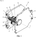
- FIG. 1 schematically illustrates a control mechanism 10 for an electrical connection apparatus located on a medium voltage or high voltage power line.
- the terms “medium voltage” and “high voltage” are used in their usual meaning, namely that the term “medium voltage” designates a voltage which is greater than 1,000 volts in alternating current and 1,500 volts in direct current but which does not exceed 52,000 volts in alternating current and 75,000 volts in direct current, while the term “high voltage” designates a voltage which is strictly greater than 52,000 volts in alternating current and 75,000 volts in direct current.
- such a control mechanism 10 comprises a main contact operating member 12 for controlling the opening or closing of an electrical line, as well as a system 14 for transmitting movement between the main contact operating member 12 and a set of auxiliary contacts 11.
- the auxiliary contact assembly 11 essentially comprises, as illustrated, a shaft 16, a plurality of microcontacts 18, and a support 25.
- the shaft 16 is connected to the transmission system 14 of the main contacts.
- the shaft 16 is rotatable about an axis A.
- the shaft 16 is intended to be driven in rotation about its axis A by the transmission system 14 during a movement of the operating member 12.
- the shaft 16 may in particular comprise a toothed wheel 19 to be driven by gears during the movement of the operating member 12.
- the shaft 16 is secured to a plurality of actuators 20, arranged regularly along the axis A.
- Each actuator 20 is arranged opposite one of the microcontacts 18, to mechanically actuate the microcontact 18 during rotation of the shaft 16 around the axis A.
- the support 25 makes it possible to mount the shaft 16 and the plurality of microcontacts 18 in the control mechanism 10.
- the support 25 here has a first plate 22 and a second plate 24, arranged facing the first plate 22.
- the shaft 16 is arranged between the plates 22, 24, in the transverse direction. Thus, the shaft 16 can be connected to the plates 22, 24, while being movable in rotation relative to the plates 22, 24.
- the support 25 also has a base 26 extending between the plates 22, 24.
- the base 26 comprises a plurality of cells 28, each cell 28 defining a housing 28 for one of the microcontacts 18.
- the device 30 comprises the microcontact 18, the actuator 20 and an elastic blade 32.
- the elastic blade 32 extends between the actuator 20 and the microcontact 18, to intervene in the actuation of the microcontact 18.
- the microswitch 18 essentially comprises a body 33 and a movable member 34 mounted on the body 33.
- the body 33 here has three blades 35, 36, 38, projecting from a housing 40 of the body 33.
- a first blade 35 defines a power supply terminal 35 of the microcontact 18, to be connected to a voltage or current source.
- a second blade 36 and a third blade 38 respectively define a normally open terminal 36 and a normally closed terminal 38 of the microcontact 18, to be connected to an electrical circuit.
- the housing 40 contains a set of internal contacts, to place the power supply terminal 35 in electrical contact with the normally open terminal 36 or the normally closed terminal 38 of the microcontact 18.
- a movement of the movable member 34 causes the set of internal contacts to be permuted.
- the movable member 34 here takes the form of a pallet 34.
- the pallet 34 interacts with a pusher 41, provided with a return spring, to define a rest position and an active position of the pallet 34. In the rest position, the pallet 34 does not exert any force on the pusher 41. Only the spring acts on the pusher 41.
- the power supply terminal 35 is in electrical contact with the normally closed terminal 38. In the active position, the pallet 34 is moved under the effect of a force exerted on the pallet 34, to press on the pusher 41, against the action of the return spring.
- the power supply terminal 35 is placed in electrical contact with the normally open terminal 36.
- the actuator 20 comprises a cam 42.
- the cam 42 takes the form of a projection extending radially outward relative to the axis A.
- the actuator 20 can adopt a first angular position, shown in figure 2 , in which the cam 42 presses on the movable member 34 of the microcontact 18, to maintain the movable member 34 in the active position.
- the first angular position may in particular correspond to the closing of the line and to a closed state of the electrical connection device.
- a second angular position of the actuator 20 shown in figure 5 obtained by rotation around the axis A, the cam 42 is separated from the movable member 34 of the microcontact 18.
- the microcontact 18 is released from the actuator 20.
- the second angular position can correspond to the opening of the line and to an open state of the electrical connection device.
- the cam 42 may comprise a ramp 44.
- the ramp 44 extends on the side of the actuator 20 coming into contact with the movable member 34 during rotation of the actuator 20 from the second angular position to the first angular position.
- the force exerted by the cam 42 on the movable member 34 is progressive.
- the permutation from the rest position to the active position of the movable member 34 may be controlled by the ramp 44.
- the elastic blade 32 has, from one end in the vicinity of the actuator 20 to one end in the vicinity of the microcontact 18, a portion curved 46, a tab 48 and a fixing lug 50.
- the elastic blade 32 intervenes in the actuation of the movable member 34 of the microswitch 18 during the rotation of the actuator 20 from the first angular position to the second angular position.
- the permutation of the active position to the rest position of the movable member 34 can be controlled by the elastic blade 32.
- the curved portion 46 extends around the axis A of the actuator 20.
- the curved portion 46 defines a concavity facing the axis A.
- the curved portion 46 can be elastically biased by the cam 42 of the actuator 20.
- the curved portion 46 extends over a portion of the arc of a circle traveled by the cam 42 during a rotation from one of the first and second angular positions to the other of the first and second angular positions of the actuator 20.
- the curved portion 46 is released from the cam 42 when the actuator 20 is in the first or second angular position.
- the free end of the curved portion 46 bears on the actuator 20.
- the curved portion 46 is bent between the free end and the tab 48. In this case, the bending makes it possible to gradually move the curved portion 46 away from the actuator 20 relative to the axis A, over the entire extent of the curved portion 46.
- the other end of the curved portion 46 is connected to the tab 48 by a joint 53.
- the joint 53 is arranged facing the movable member 34.
- the joint 53 is rounded.
- the joint 53 defines a convexity oriented towards the movable member 34.
- the joint 53 is intended to allow the passage of the movable member 34 during its movement towards the active position.
- straight lines D1 and D2 define the shape of the articulation 53.
- the straight line D1 is tangent to the arc of a circle traveled by the movable member 34 during the permutation between one of the active position and the rest position to the other of the rest position and the active position of the microswitch 18.
- the straight line D2 is tangent to the curved portion 46, in the vicinity of the tab 48.
- the two ends of the articulation 53 connect the straight lines D1 and D2 along a radius R. The shape of the articulation 53 thus makes it possible to prevent the movable member 34 from remaining blocked by the elastic blade 32.
- the tab 48 has a substantially “V” shape.
- a first branch 52 of the “V” extends from a vertex 56 of the “V” to the articulation 53.
- the first branch 52 extends in the extension of the articulation 53.
- the first branch 52 is intended to come into contact with the movable member 34.
- the first branch 52 blocks the passage of the movable member 34.
- the first branch 52 blocks the movable member 34 by exerting a force on the movable member 34.
- the force exerted generates a holding torque for the movable member 34, greater than a release torque for the movable member 34 generated by the action of the return spring on the pusher 41.
- the movable member 34 could be blocked by friction or attachment of the movable member 34 to the first branch 52.
- the first branch 52 here allows the movable member 34 to slide along the first branch 52.
- a second branch 54 of the “V” extends from the apex 56 to an end in the vicinity of the microcontact 18.
- the geometry of the tab 48 can allow the translation of the first branch 52 around the apex 56 connecting the two branches 52, 54.
- the translation allows the first branch 52 to be separated from the movable member 34.
- the “V” shape facilitates the manufacture of the elastic blade 32.
- the tab 48 can take any other shape to allow the first branch 52 to be moved for the passage of the movable member 34 between the active position and the rest position.
- the angle formed by the first and second branches 52, 54 can be more or less open.
- the apex 56 of the “V” can also be more or less rounded.
- the fixing lug 50 extends here along the body 33 of the microcontact 18.
- the fixing lug 50 is secured to the body 33 of the microcontact 18.
- the fixing lug 50 makes it possible to arrange the elastic blade 32 in the device 30. This prevents the elastic blade 32 from moving when the elastic blade 32 is stressed by the cam 42 of the actuator 20.
- the base 26 may be devoid of means for fixing the elastic blade 32, facilitating the manufacture of the base 26 and the assembly of the device 30.
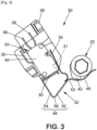
- the actuator 20 can adopt a first and a second intermediate position, illustrated respectively by the figures 3 And 4 , moving from the first angular position to the second angular position.
- the first and second intermediate positions correspond to a position of the actuator 20 during opening of the electrical connection device.
- the second intermediate position is subsequent to the first intermediate position during the movement of the actuator 20, and is associated with the release of the microcontact 18 from the elastic blade 32.
- the cam 42 of the actuator 20 comes into contact with the curved portion 46.
- the elastic blade 32 is not stressed by the cam 42 until the actuator 20 is in the first intermediate position.
- the end of the cam 42 is in the vicinity of the free end of the curved portion 46.
- the cam 42 presses on the curved portion 46.
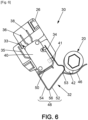
- the actuator 20 can also adopt a third intermediate position, illustrated by the figure 6 , moving from the second angular position to the first angular position.
- the third intermediate position corresponds to a position of the actuator 20 in the process of closing the electrical connection device.
- the actuator 20 is in the first angular position, illustrated in figure 2 .
- the cam 42 of the actuator 20 acts on the movable member 34 of the microcontact 18 to maintain the movable member 34 in the active position.
- the power supply terminal 35 of the microcontact 18 is connected to the normally open terminal 36 of the microcontact 18.
- the current flowing through the microcontact 18 can for example inform that the line is in the closed position.
- the actuator 20 is driven to the second angular position, illustrated in figure 5 .
- the cam 42 of the actuator 20 releases the movable member 34.
- the elastic blade 32 holds the movable member 34 of the microswitch 18 in active position.
- the movable member 34 is held in active position. under the effect of the tab 48, in particular of the first branch 52 of the tab 48.
- the first branch 52 blocks the passage of the movable member 34.
- the cam 42 of the actuator 20 comes into contact with the curved portion 46 of the elastic blade 32, then exerts an increasing force on the curved portion 46.
- the force exerted on the curved portion 46 by the cam 42 causes the translation of the first branch 52 of the elastic blade 32.
- the force exerted by the cam 42 of the actuator 20 on the curved portion 46 decreases.
- the ramp 44 of the cam 42 gradually returns the curved portion 46 of the elastic blade 32 to the initial position of the figure 2 .
- the cam 42 of the actuator 20 is separated from the movable member 34 and from the elastic blade 32.
- the elastic blade 32 is in the initial position of the figure 2 .
- the movable member 34 of the microcontact 18 is in the rest position.
- the power supply terminal 35 of the microcontact 18 is connected to the normally closed terminal 38 of the microcontact 18.
- the current flowing through the microcontact 18 can for example inform that the line is in an open position.
- the actuator 20 is driven to the first angular position of the figure 2 .
- the cam 42 of the actuator 20 comes into contact with the curved portion 46 of the elastic blade 32, then exerts a force on the curved portion 46.
- the ramp 44 comes into contact with the movable member 34, to gradually push the movable contact 34 towards the active position.
- the movement of the movable member 34 brings the movable member 34 closer to the articulation 53 of the elastic blade 32.
- the articulation 53 allows the passage of the movable member 34.
- the movable member 34 can then come into contact with the first branch 52, then slide along the first branch 52.
- the second angular position of the actuator 20 can correspond to the grounding of the line.
- the device 30 can then provide information about the grounding of the line.
Landscapes
- Rotary Switch, Piano Key Switch, And Lever Switch (AREA)
- Push-Button Switches (AREA)
- Mechanisms For Operating Contacts (AREA)
Claims (13)
- Vorrichtung (30) zur Interaktion mit einem Mikrokontakt (18), beinhaltend:- einen Betätiger (20), der zwischen mindestens einer ersten Winkelposition und einer zweiten Winkelposition drehbar um eine Achse (A) montiert ist;- einen Mikrokontakt (18), der einen Körper (33) und ein mobiles Organ (34), das an dem Körper (33) montiert und zwischen einer aktiven Position und einer Ruheposition bewegbar ist, beinhaltet;wobei das mobile Organ (34) in der aktiven Position gehalten wird, wenn der Betätiger (20) zwischen der ersten Winkelposition und einer ersten Zwischenposition bewegt wird, wobei sich die erste Zwischenposition zwischen der ersten Winkelposition und der zweiten Winkelposition befindet,dadurch gekennzeichnet, dass die Interaktionsvorrichtung ein elastisches Blatt (32) beinhaltet, das dazu angepasst ist, das mobile Organ (34) in der aktiven Position zu halten,wobei der Betätiger (20) dazu angepasst ist, das elastische Blatt (32) so zu bewegen, dass das mobile Organ (34) in die Ruheposition übergeht, wenn der Betätiger (20) zwischen der ersten Zwischenposition und einer zweiten Zwischenposition bewegt wird, wobei sich die zweite Zwischenposition zwischen der ersten Zwischenposition und der zweiten Winkelposition befindet.
- Vorrichtung nach Anspruch 1, wobei der Betätiger (20) eine Nocke (42) beinhaltet, die dazu angepasst ist, auf das mobile Organ (34) des Mikrokontakts (18) zu drücken und das elastische Blatt (32) zu verformen.
- Vorrichtung nach Anspruch 2, wobei die Nocke (42) eine Rampe (44) beinhaltet, die dazu angepasst ist, eine progressive Bewegung des mobilen Organs (34) zu gestatten.
- Vorrichtung nach einem der Ansprüche 1 bis 3, wobei das elastische Blatt (32) einen gekrümmten Abschnitt (46) beinhaltet, auf den der Betätiger (20) einwirkt, wobei der gekrümmte Abschnitt (46) eine zu der Achse (A) des Betätigers (20) gerichtete Konkavität aufweist.
- Vorrichtung nach Anspruch 4, wobei sich der gekrümmte Abschnitt (46) zu dem mobilen Organ (34) erstreckt und dabei einen zunehmenden Abstand zu der Achse (A) aufweist, sodass das elastische Blatt (32) durch den Druck des Betätigers (20) auf den gekrümmten Abschnitt (46) zwischen der ersten und der zweiten Zwischenposition progressiv verformt wird.
- Vorrichtung nach einem der Ansprüche 4 oder 5, wobei das elastische Blatt (32) eine Zunge (48) beinhaltet, die sich in Verlängerung des gekrümmten Abschnitts (46) erstreckt und dazu angepasst ist, das mobile Organ (34) zwischen der ersten Winkelposition und der ersten Zwischenposition in der aktiven Position zu halten.
- Vorrichtung nach Anspruch 6, wobei die Zunge (48) im Wesentlichen eine "V"-Form aufweist, die einen Scheitelpunkt (56), einen ersten Arm (52), der sich von dem Scheitelpunkt (56) bis zu einem ersten Ende erstreckt, einen zweiten Arm (54), der sich von dem Scheitelpunkt (56) bis zu einem zweiten Ende erstreckt, beinhaltet, wobei sich das zweite Ende in der Nähe des Körpers (33) des Mikrokontakts (18) befindet und sich das erste Ende in der Nähe des mobilen Organs (34) des Mikrokontakts (18) befindet.
- Vorrichtung nach Anspruch 7, wobei sich der erste Arm (52) gemäß einer zu der Bahn des mobilen Organs (34) tangentialen Richtung erstreckt, sodass das mobile Organ (34) bei der Bewegung des mobilen Organs (34) mit dem ersten Arm (52) in Kontakt kommt.
- Vorrichtung nach einem der Ansprüche 6 bis 8, wobei das elastische Blatt (32) eine Befestigungslasche (50) beinhaltet, die sich in Verlängerung des zweiten Endes der Zunge (48) erstreckt und mit dem Körper (33) des Mikrokontakts (18) fest verbunden ist.
- Vorrichtung nach einem beliebigen der vorhergehenden Ansprüche, wobei der Betätiger (20) bei einer Positionsänderung von elektrischen Hauptkontakten in einer elektrischen Leitung in Drehung versetzt wird.
- Anordnung (10) von elektrischen Hilfskontakten, die eine Vielzahl von Vorrichtungen (30) nach einem beliebigen der vorhergehenden Ansprüche und eine Welle (16), die die Betätiger (20) jeder Vorrichtung (30) drehfest miteinander verbindet, beinhaltet.
- Anordnung (10) von elektrischen Hilfskontakten nach Anspruch 11, wobei die Welle (16) durch Zahnräder mit einem Schaltorgan (12) für Hauptkontakte in einer elektrischen Leitung verbunden ist.
- Elektrisches Anschlussgerät, das eine Anordnung (10) nach einem der Ansprüche 11 oder 12 beinhaltet.
Applications Claiming Priority (1)
| Application Number | Priority Date | Filing Date | Title |
|---|---|---|---|
| FR2009453A FR3114435A1 (fr) | 2020-09-18 | 2020-09-18 | Dispositif pour le contrôle d’un microcontact dans un appareil de connexion électrique |
Publications (2)
| Publication Number | Publication Date |
|---|---|
| EP3971934A1 EP3971934A1 (de) | 2022-03-23 |
| EP3971934B1 true EP3971934B1 (de) | 2024-10-30 |
Family
ID=73643054
Family Applications (1)
| Application Number | Title | Priority Date | Filing Date |
|---|---|---|---|
| EP21181668.1A Active EP3971934B1 (de) | 2020-09-18 | 2021-06-25 | Vorrichtung zur steuerung eines mikrokontakts in einem elektrischen anschlussgerät |
Country Status (3)
| Country | Link |
|---|---|
| EP (1) | EP3971934B1 (de) |
| CN (1) | CN114203463A (de) |
| FR (1) | FR3114435A1 (de) |
Family Cites Families (11)
| Publication number | Priority date | Publication date | Assignee | Title |
|---|---|---|---|---|
| DE4110327C1 (en) * | 1991-03-28 | 1992-07-30 | S. Siedle & Soehne Telefon- Und Telegrafenwerke Stiftung & Co, 7743 Furtwangen, De | Actuator for pushbutton microswitch - has lever pivoted by rod to press operating button of cradle switch of telephone subscriber's appts. when handset is replaced |
| DE19860042A1 (de) * | 1998-12-23 | 2000-07-06 | Aeg Niederspannungstech Gmbh | Betätigungselement zur Herstellung einer Schaltverbindung zwischen einem Hauptschalter und einem Hilfsschalter |
| KR100876412B1 (ko) * | 2007-07-12 | 2008-12-31 | 엘에스산전 주식회사 | 차단기의 지연시간 출력장치 |
| CN101436493B (zh) * | 2008-12-05 | 2011-01-12 | 常熟开关制造有限公司(原常熟开关厂) | 断路器辅助开关 |
| CN102386002B (zh) * | 2010-08-31 | 2014-11-26 | 西门子公司 | 辅助开关及其切换装置 |
| CN202816820U (zh) * | 2012-08-17 | 2013-03-20 | 上海电科电器科技有限公司 | 断路器的辅助开关 |
| EP3166121B1 (de) * | 2015-11-03 | 2019-03-27 | C&K Components SAS | Elektrischer drucktastenschalter |
| FR3061987B1 (fr) * | 2017-01-16 | 2019-04-19 | Schneider Electric Industries Sas | Integration de contacts electriques a un appareil de connexion electrique |
| FR3087273B1 (fr) * | 2018-10-15 | 2020-11-06 | Schneider Electric Ind Sas | Dispositif de mesure et appareil de commutation electrique |
| CN209118946U (zh) * | 2018-12-04 | 2019-07-16 | 四川凌峰航空液压机械有限公司 | 微动开关缓冲促动机构 |
| CN210378863U (zh) * | 2019-10-28 | 2020-04-21 | 保定天威恒通电气有限公司 | 一种便于扩展安装的隔离开关辅助触点装置 |
-
2020
- 2020-09-18 FR FR2009453A patent/FR3114435A1/fr not_active Ceased
-
2021
- 2021-06-25 EP EP21181668.1A patent/EP3971934B1/de active Active
- 2021-08-17 CN CN202110941108.0A patent/CN114203463A/zh active Pending
Also Published As
| Publication number | Publication date |
|---|---|
| CN114203463A (zh) | 2022-03-18 |
| EP3971934A1 (de) | 2022-03-23 |
| FR3114435A1 (fr) | 2022-03-25 |
Similar Documents
| Publication | Publication Date | Title |
|---|---|---|
| EP0570647B1 (de) | Schaltschloss für Schutzschalter und Schutzschalter, mit diesem integriert | |
| EP2061059B1 (de) | Steuervorrichtung für ein elektrisches Unterbrechungsgerät und elektrisches Unterbrechungsgerät, das damit ausgestattet ist | |
| EP0161120B1 (de) | Anordnung zur Lastunterbrechung und sichtbaren Trennung eines elektrischen Stromkreises | |
| FR2789511A1 (fr) | Installation comportant un appareillage electrique de coupure et un interverrouillage a cable | |
| EP2061058B1 (de) | Steuervorrichtung für ein elektrisches Unterbrechungsgerät und elektrisches Unterbrechungsgerät, das damit ausgestattet ist | |
| EP3487006B1 (de) | Elektrisches system, das ein elektrogerät und ein auswechselbares verbindungsmodul umfasst | |
| FR2597658A1 (fr) | Commutateur miniature a rupture brusque | |
| FR3056330A1 (fr) | Dispositif de coupure comportant un organe de rearmement | |
| EP2365510B1 (de) | Leistungsschalter | |
| EP0564379B1 (de) | Schwenkhebelbetätigungsmechanismus für Schutzschalter mit Phasen- und Neutralleiter | |
| EP2717284B1 (de) | Bedienungsvorrichtung eines elektrischen Schutzschaltgeräts, und diese umfassendes elektrisches Schutzschaltgerät | |
| EP3971934A1 (de) | Vorrichtung zur steuerung eines mikrokontakts in einem elektrischen anschlussgerät | |
| EP1734552B1 (de) | Betätigungseinrichtung eines elektrischen Schaltgeräts mit Drehsperre | |
| EP0564380B1 (de) | Antriebsmechanismus mit Schieber für elektrischen Lastschalter mit Nulleiter-Schalter | |
| EP0209433B1 (de) | Kontaktträger, insbesondere für Schutzschalter | |
| EP0891627B1 (de) | Modulare elektrische schalteranordung | |
| EP2061060B1 (de) | Elektrisches Schaltgerät wie etwa ein Leistungsschalter oder Schalter | |
| EP3605581B1 (de) | Elektrisches schaltgerät mit trennbaren kontakten | |
| FR2735609A1 (fr) | Mecanisme d'interrupteur | |
| EP1296342B1 (de) | Trennschalter mit Sicherung mit einem Sicherungshalter und einem Bedienelement für eine Sicherungsschaltung | |
| EP3792949B1 (de) | Elektrische schaltvorrichtung mit trennbaren kontakten | |
| EP0517639B1 (de) | Steckverbinder mit geringem Platzbedarf für die Anschlussklemme einer Kraftfahrzeugbatterie | |
| EP1632970B1 (de) | Elektromagnetische Auslöser und elektronischer Schutzschalter, die es enthält. | |
| FR2626712A1 (fr) | Interrupteur electrique a coupure automatique, en particulier interrupteur differentiel | |
| FR2530072A1 (fr) | Dispositif commutateur, notamment disjoncteur du type a enclenchement par enfoncement puis relachement d'un bouton-poussoir et a declenchement par la deformation d'une lame bimetallique |
Legal Events
| Date | Code | Title | Description |
|---|---|---|---|
| PUAI | Public reference made under article 153(3) epc to a published international application that has entered the european phase |
Free format text: ORIGINAL CODE: 0009012 |
|
| STAA | Information on the status of an ep patent application or granted ep patent |
Free format text: STATUS: THE APPLICATION HAS BEEN PUBLISHED |
|
| AK | Designated contracting states |
Kind code of ref document: A1 Designated state(s): AL AT BE BG CH CY CZ DE DK EE ES FI FR GB GR HR HU IE IS IT LI LT LU LV MC MK MT NL NO PL PT RO RS SE SI SK SM TR |
|
| STAA | Information on the status of an ep patent application or granted ep patent |
Free format text: STATUS: REQUEST FOR EXAMINATION WAS MADE |
|
| 17P | Request for examination filed |
Effective date: 20220913 |
|
| RBV | Designated contracting states (corrected) |
Designated state(s): AL AT BE BG CH CY CZ DE DK EE ES FI FR GB GR HR HU IE IS IT LI LT LU LV MC MK MT NL NO PL PT RO RS SE SI SK SM TR |
|
| GRAP | Despatch of communication of intention to grant a patent |
Free format text: ORIGINAL CODE: EPIDOSNIGR1 |
|
| STAA | Information on the status of an ep patent application or granted ep patent |
Free format text: STATUS: GRANT OF PATENT IS INTENDED |
|
| INTG | Intention to grant announced |
Effective date: 20240321 |
|
| GRAJ | Information related to disapproval of communication of intention to grant by the applicant or resumption of examination proceedings by the epo deleted |
Free format text: ORIGINAL CODE: EPIDOSDIGR1 |
|
| STAA | Information on the status of an ep patent application or granted ep patent |
Free format text: STATUS: REQUEST FOR EXAMINATION WAS MADE |
|
| GRAP | Despatch of communication of intention to grant a patent |
Free format text: ORIGINAL CODE: EPIDOSNIGR1 |
|
| STAA | Information on the status of an ep patent application or granted ep patent |
Free format text: STATUS: GRANT OF PATENT IS INTENDED |
|
| INTC | Intention to grant announced (deleted) | ||
| INTG | Intention to grant announced |
Effective date: 20240619 |
|
| GRAJ | Information related to disapproval of communication of intention to grant by the applicant or resumption of examination proceedings by the epo deleted |
Free format text: ORIGINAL CODE: EPIDOSDIGR1 |
|
| STAA | Information on the status of an ep patent application or granted ep patent |
Free format text: STATUS: REQUEST FOR EXAMINATION WAS MADE |
|
| INTC | Intention to grant announced (deleted) | ||
| GRAP | Despatch of communication of intention to grant a patent |
Free format text: ORIGINAL CODE: EPIDOSNIGR1 |
|
| STAA | Information on the status of an ep patent application or granted ep patent |
Free format text: STATUS: GRANT OF PATENT IS INTENDED |
|
| GRAS | Grant fee paid |
Free format text: ORIGINAL CODE: EPIDOSNIGR3 |
|
| GRAA | (expected) grant |
Free format text: ORIGINAL CODE: 0009210 |
|
| STAA | Information on the status of an ep patent application or granted ep patent |
Free format text: STATUS: THE PATENT HAS BEEN GRANTED |
|
| INTG | Intention to grant announced |
Effective date: 20240919 |
|
| AK | Designated contracting states |
Kind code of ref document: B1 Designated state(s): AL AT BE BG CH CY CZ DE DK EE ES FI FR GB GR HR HU IE IS IT LI LT LU LV MC MK MT NL NO PL PT RO RS SE SI SK SM TR |
|
| REG | Reference to a national code |
Ref country code: GB Ref legal event code: FG4D Free format text: NOT ENGLISH |
|
| REG | Reference to a national code |
Ref country code: CH Ref legal event code: EP |
|
| REG | Reference to a national code |
Ref country code: DE Ref legal event code: R096 Ref document number: 602021020883 Country of ref document: DE |
|
| REG | Reference to a national code |
Ref country code: IE Ref legal event code: FG4D Free format text: LANGUAGE OF EP DOCUMENT: FRENCH |
|
| REG | Reference to a national code |
Ref country code: LT Ref legal event code: MG9D |
|
| REG | Reference to a national code |
Ref country code: NL Ref legal event code: MP Effective date: 20241030 |
|
| PG25 | Lapsed in a contracting state [announced via postgrant information from national office to epo] |
Ref country code: PT Free format text: LAPSE BECAUSE OF FAILURE TO SUBMIT A TRANSLATION OF THE DESCRIPTION OR TO PAY THE FEE WITHIN THE PRESCRIBED TIME-LIMIT Effective date: 20250228 Ref country code: IS Free format text: LAPSE BECAUSE OF FAILURE TO SUBMIT A TRANSLATION OF THE DESCRIPTION OR TO PAY THE FEE WITHIN THE PRESCRIBED TIME-LIMIT Effective date: 20250228 Ref country code: HR Free format text: LAPSE BECAUSE OF FAILURE TO SUBMIT A TRANSLATION OF THE DESCRIPTION OR TO PAY THE FEE WITHIN THE PRESCRIBED TIME-LIMIT Effective date: 20241030 |
|
| PG25 | Lapsed in a contracting state [announced via postgrant information from national office to epo] |
Ref country code: NL Free format text: LAPSE BECAUSE OF FAILURE TO SUBMIT A TRANSLATION OF THE DESCRIPTION OR TO PAY THE FEE WITHIN THE PRESCRIBED TIME-LIMIT Effective date: 20241030 Ref country code: FI Free format text: LAPSE BECAUSE OF FAILURE TO SUBMIT A TRANSLATION OF THE DESCRIPTION OR TO PAY THE FEE WITHIN THE PRESCRIBED TIME-LIMIT Effective date: 20241030 |
|
| REG | Reference to a national code |
Ref country code: AT Ref legal event code: MK05 Ref document number: 1737793 Country of ref document: AT Kind code of ref document: T Effective date: 20241030 |
|
| PG25 | Lapsed in a contracting state [announced via postgrant information from national office to epo] |
Ref country code: BG Free format text: LAPSE BECAUSE OF FAILURE TO SUBMIT A TRANSLATION OF THE DESCRIPTION OR TO PAY THE FEE WITHIN THE PRESCRIBED TIME-LIMIT Effective date: 20241030 |
|
| PG25 | Lapsed in a contracting state [announced via postgrant information from national office to epo] |
Ref country code: ES Free format text: LAPSE BECAUSE OF FAILURE TO SUBMIT A TRANSLATION OF THE DESCRIPTION OR TO PAY THE FEE WITHIN THE PRESCRIBED TIME-LIMIT Effective date: 20241030 |
|
| PG25 | Lapsed in a contracting state [announced via postgrant information from national office to epo] |
Ref country code: NO Free format text: LAPSE BECAUSE OF FAILURE TO SUBMIT A TRANSLATION OF THE DESCRIPTION OR TO PAY THE FEE WITHIN THE PRESCRIBED TIME-LIMIT Effective date: 20250130 |
|
| PG25 | Lapsed in a contracting state [announced via postgrant information from national office to epo] |
Ref country code: LV Free format text: LAPSE BECAUSE OF FAILURE TO SUBMIT A TRANSLATION OF THE DESCRIPTION OR TO PAY THE FEE WITHIN THE PRESCRIBED TIME-LIMIT Effective date: 20241030 Ref country code: GR Free format text: LAPSE BECAUSE OF FAILURE TO SUBMIT A TRANSLATION OF THE DESCRIPTION OR TO PAY THE FEE WITHIN THE PRESCRIBED TIME-LIMIT Effective date: 20250131 Ref country code: AT Free format text: LAPSE BECAUSE OF FAILURE TO SUBMIT A TRANSLATION OF THE DESCRIPTION OR TO PAY THE FEE WITHIN THE PRESCRIBED TIME-LIMIT Effective date: 20241030 |
|
| PG25 | Lapsed in a contracting state [announced via postgrant information from national office to epo] |
Ref country code: PL Free format text: LAPSE BECAUSE OF FAILURE TO SUBMIT A TRANSLATION OF THE DESCRIPTION OR TO PAY THE FEE WITHIN THE PRESCRIBED TIME-LIMIT Effective date: 20241030 |
|
| PG25 | Lapsed in a contracting state [announced via postgrant information from national office to epo] |
Ref country code: RS Free format text: LAPSE BECAUSE OF FAILURE TO SUBMIT A TRANSLATION OF THE DESCRIPTION OR TO PAY THE FEE WITHIN THE PRESCRIBED TIME-LIMIT Effective date: 20250130 |
|
| PG25 | Lapsed in a contracting state [announced via postgrant information from national office to epo] |
Ref country code: SM Free format text: LAPSE BECAUSE OF FAILURE TO SUBMIT A TRANSLATION OF THE DESCRIPTION OR TO PAY THE FEE WITHIN THE PRESCRIBED TIME-LIMIT Effective date: 20241030 |
|
| PGFP | Annual fee paid to national office [announced via postgrant information from national office to epo] |
Ref country code: DE Payment date: 20250626 Year of fee payment: 5 |
|
| PG25 | Lapsed in a contracting state [announced via postgrant information from national office to epo] |
Ref country code: DK Free format text: LAPSE BECAUSE OF FAILURE TO SUBMIT A TRANSLATION OF THE DESCRIPTION OR TO PAY THE FEE WITHIN THE PRESCRIBED TIME-LIMIT Effective date: 20241030 |
|
| PGFP | Annual fee paid to national office [announced via postgrant information from national office to epo] |
Ref country code: GB Payment date: 20250617 Year of fee payment: 5 |
|
| PG25 | Lapsed in a contracting state [announced via postgrant information from national office to epo] |
Ref country code: EE Free format text: LAPSE BECAUSE OF FAILURE TO SUBMIT A TRANSLATION OF THE DESCRIPTION OR TO PAY THE FEE WITHIN THE PRESCRIBED TIME-LIMIT Effective date: 20241030 |
|
| PGFP | Annual fee paid to national office [announced via postgrant information from national office to epo] |
Ref country code: FR Payment date: 20250624 Year of fee payment: 5 |
|
| PG25 | Lapsed in a contracting state [announced via postgrant information from national office to epo] |
Ref country code: RO Free format text: LAPSE BECAUSE OF FAILURE TO SUBMIT A TRANSLATION OF THE DESCRIPTION OR TO PAY THE FEE WITHIN THE PRESCRIBED TIME-LIMIT Effective date: 20241030 |
|
| PG25 | Lapsed in a contracting state [announced via postgrant information from national office to epo] |
Ref country code: SK Free format text: LAPSE BECAUSE OF FAILURE TO SUBMIT A TRANSLATION OF THE DESCRIPTION OR TO PAY THE FEE WITHIN THE PRESCRIBED TIME-LIMIT Effective date: 20241030 |
|
| PG25 | Lapsed in a contracting state [announced via postgrant information from national office to epo] |
Ref country code: CZ Free format text: LAPSE BECAUSE OF FAILURE TO SUBMIT A TRANSLATION OF THE DESCRIPTION OR TO PAY THE FEE WITHIN THE PRESCRIBED TIME-LIMIT Effective date: 20241030 |
|
| PG25 | Lapsed in a contracting state [announced via postgrant information from national office to epo] |
Ref country code: IT Free format text: LAPSE BECAUSE OF FAILURE TO SUBMIT A TRANSLATION OF THE DESCRIPTION OR TO PAY THE FEE WITHIN THE PRESCRIBED TIME-LIMIT Effective date: 20241030 |
|
| REG | Reference to a national code |
Ref country code: DE Ref legal event code: R097 Ref document number: 602021020883 Country of ref document: DE |
|
| PLBE | No opposition filed within time limit |
Free format text: ORIGINAL CODE: 0009261 |
|
| STAA | Information on the status of an ep patent application or granted ep patent |
Free format text: STATUS: NO OPPOSITION FILED WITHIN TIME LIMIT |
|
| PG25 | Lapsed in a contracting state [announced via postgrant information from national office to epo] |
Ref country code: SE Free format text: LAPSE BECAUSE OF FAILURE TO SUBMIT A TRANSLATION OF THE DESCRIPTION OR TO PAY THE FEE WITHIN THE PRESCRIBED TIME-LIMIT Effective date: 20241030 |
|
| 26N | No opposition filed |
Effective date: 20250731 |
|
| REG | Reference to a national code |
Ref country code: CH Ref legal event code: H13 Free format text: ST27 STATUS EVENT CODE: U-0-0-H10-H13 (AS PROVIDED BY THE NATIONAL OFFICE) Effective date: 20260127 |
|
| PG25 | Lapsed in a contracting state [announced via postgrant information from national office to epo] |
Ref country code: MC Free format text: LAPSE BECAUSE OF FAILURE TO SUBMIT A TRANSLATION OF THE DESCRIPTION OR TO PAY THE FEE WITHIN THE PRESCRIBED TIME-LIMIT Effective date: 20241030 |
|
| PG25 | Lapsed in a contracting state [announced via postgrant information from national office to epo] |
Ref country code: LU Free format text: LAPSE BECAUSE OF NON-PAYMENT OF DUE FEES Effective date: 20250625 |
|
| REG | Reference to a national code |
Ref country code: BE Ref legal event code: MM Effective date: 20250630 |
|
| PG25 | Lapsed in a contracting state [announced via postgrant information from national office to epo] |
Ref country code: IE Free format text: LAPSE BECAUSE OF NON-PAYMENT OF DUE FEES Effective date: 20250625 |
|
| PG25 | Lapsed in a contracting state [announced via postgrant information from national office to epo] |
Ref country code: BE Free format text: LAPSE BECAUSE OF NON-PAYMENT OF DUE FEES Effective date: 20250630 |
|
| PG25 | Lapsed in a contracting state [announced via postgrant information from national office to epo] |
Ref country code: CH Free format text: LAPSE BECAUSE OF NON-PAYMENT OF DUE FEES Effective date: 20250630 |