EP3971487B1 - Vorrichtung zur luftbefeuchtung und -reinigung - Google Patents
Vorrichtung zur luftbefeuchtung und -reinigung Download PDFInfo
- Publication number
- EP3971487B1 EP3971487B1 EP20826869.8A EP20826869A EP3971487B1 EP 3971487 B1 EP3971487 B1 EP 3971487B1 EP 20826869 A EP20826869 A EP 20826869A EP 3971487 B1 EP3971487 B1 EP 3971487B1
- Authority
- EP
- European Patent Office
- Prior art keywords
- air
- humidification
- flow path
- regulating member
- water
- Prior art date
- Legal status (The legal status is an assumption and is not a legal conclusion. Google has not performed a legal analysis and makes no representation as to the accuracy of the status listed.)
- Active
Links
Images


Classifications
-
- F—MECHANICAL ENGINEERING; LIGHTING; HEATING; WEAPONS; BLASTING
- F24—HEATING; RANGES; VENTILATING
- F24F—AIR-CONDITIONING; AIR-HUMIDIFICATION; VENTILATION; USE OF AIR CURRENTS FOR SCREENING
- F24F8/00—Treatment, e.g. purification, of air supplied to human living or working spaces otherwise than by heating, cooling, humidifying or drying
- F24F8/10—Treatment, e.g. purification, of air supplied to human living or working spaces otherwise than by heating, cooling, humidifying or drying by separation, e.g. by filtering
-
- B—PERFORMING OPERATIONS; TRANSPORTING
- B01—PHYSICAL OR CHEMICAL PROCESSES OR APPARATUS IN GENERAL
- B01D—SEPARATION
- B01D46/00—Filters or filtering processes specially modified for separating dispersed particles from gases or vapours
- B01D46/0039—Filters or filtering processes specially modified for separating dispersed particles from gases or vapours with flow guiding by feed or discharge devices
- B01D46/0047—Filters or filtering processes specially modified for separating dispersed particles from gases or vapours with flow guiding by feed or discharge devices for discharging the filtered gas
- B01D46/0049—Filters or filtering processes specially modified for separating dispersed particles from gases or vapours with flow guiding by feed or discharge devices for discharging the filtered gas containing fixed gas displacement elements or cores
-
- B—PERFORMING OPERATIONS; TRANSPORTING
- B01—PHYSICAL OR CHEMICAL PROCESSES OR APPARATUS IN GENERAL
- B01D—SEPARATION
- B01D46/00—Filters or filtering processes specially modified for separating dispersed particles from gases or vapours
- B01D46/42—Auxiliary equipment or operation thereof
- B01D46/44—Auxiliary equipment or operation thereof controlling filtration
-
- F—MECHANICAL ENGINEERING; LIGHTING; HEATING; WEAPONS; BLASTING
- F24—HEATING; RANGES; VENTILATING
- F24F—AIR-CONDITIONING; AIR-HUMIDIFICATION; VENTILATION; USE OF AIR CURRENTS FOR SCREENING
- F24F11/00—Control or safety arrangements
- F24F11/0008—Control or safety arrangements for air-humidification
-
- F—MECHANICAL ENGINEERING; LIGHTING; HEATING; WEAPONS; BLASTING
- F24—HEATING; RANGES; VENTILATING
- F24F—AIR-CONDITIONING; AIR-HUMIDIFICATION; VENTILATION; USE OF AIR CURRENTS FOR SCREENING
- F24F11/00—Control or safety arrangements
- F24F11/62—Control or safety arrangements characterised by the type of control or by internal processing, e.g. using fuzzy logic, adaptive control or estimation of values
- F24F11/63—Electronic processing
- F24F11/65—Electronic processing for selecting an operating mode
-
- F—MECHANICAL ENGINEERING; LIGHTING; HEATING; WEAPONS; BLASTING
- F24—HEATING; RANGES; VENTILATING
- F24F—AIR-CONDITIONING; AIR-HUMIDIFICATION; VENTILATION; USE OF AIR CURRENTS FOR SCREENING
- F24F13/00—Details common to, or for air-conditioning, air-humidification, ventilation or use of air currents for screening
- F24F13/08—Air-flow control members, e.g. louvres, grilles, flaps or guide plates
- F24F13/10—Air-flow control members, e.g. louvres, grilles, flaps or guide plates movable, e.g. dampers
- F24F13/14—Air-flow control members, e.g. louvres, grilles, flaps or guide plates movable, e.g. dampers built up of tilting members, e.g. louvre
-
- F—MECHANICAL ENGINEERING; LIGHTING; HEATING; WEAPONS; BLASTING
- F24—HEATING; RANGES; VENTILATING
- F24F—AIR-CONDITIONING; AIR-HUMIDIFICATION; VENTILATION; USE OF AIR CURRENTS FOR SCREENING
- F24F13/00—Details common to, or for air-conditioning, air-humidification, ventilation or use of air currents for screening
- F24F13/20—Casings or covers
-
- F—MECHANICAL ENGINEERING; LIGHTING; HEATING; WEAPONS; BLASTING
- F24—HEATING; RANGES; VENTILATING
- F24F—AIR-CONDITIONING; AIR-HUMIDIFICATION; VENTILATION; USE OF AIR CURRENTS FOR SCREENING
- F24F6/00—Air-humidification, e.g. cooling by humidification
- F24F6/02—Air-humidification, e.g. cooling by humidification by evaporation of water in the air
- F24F6/04—Air-humidification, e.g. cooling by humidification by evaporation of water in the air using stationary unheated wet elements
- F24F6/043—Air-humidification, e.g. cooling by humidification by evaporation of water in the air using stationary unheated wet elements with self-sucking action, e.g. wicks
-
- F—MECHANICAL ENGINEERING; LIGHTING; HEATING; WEAPONS; BLASTING
- F24—HEATING; RANGES; VENTILATING
- F24F—AIR-CONDITIONING; AIR-HUMIDIFICATION; VENTILATION; USE OF AIR CURRENTS FOR SCREENING
- F24F8/00—Treatment, e.g. purification, of air supplied to human living or working spaces otherwise than by heating, cooling, humidifying or drying
- F24F8/10—Treatment, e.g. purification, of air supplied to human living or working spaces otherwise than by heating, cooling, humidifying or drying by separation, e.g. by filtering
- F24F8/108—Treatment, e.g. purification, of air supplied to human living or working spaces otherwise than by heating, cooling, humidifying or drying by separation, e.g. by filtering using dry filter elements
-
- F—MECHANICAL ENGINEERING; LIGHTING; HEATING; WEAPONS; BLASTING
- F24—HEATING; RANGES; VENTILATING
- F24F—AIR-CONDITIONING; AIR-HUMIDIFICATION; VENTILATION; USE OF AIR CURRENTS FOR SCREENING
- F24F8/00—Treatment, e.g. purification, of air supplied to human living or working spaces otherwise than by heating, cooling, humidifying or drying
- F24F8/80—Self-contained air purifiers
-
- B—PERFORMING OPERATIONS; TRANSPORTING
- B01—PHYSICAL OR CHEMICAL PROCESSES OR APPARATUS IN GENERAL
- B01D—SEPARATION
- B01D2273/00—Operation of filters specially adapted for separating dispersed particles from gases or vapours
- B01D2273/30—Means for generating a circulation of a fluid in a filtration system, e.g. using a pump or a fan
-
- F—MECHANICAL ENGINEERING; LIGHTING; HEATING; WEAPONS; BLASTING
- F24—HEATING; RANGES; VENTILATING
- F24F—AIR-CONDITIONING; AIR-HUMIDIFICATION; VENTILATION; USE OF AIR CURRENTS FOR SCREENING
- F24F6/00—Air-humidification, e.g. cooling by humidification
- F24F2006/008—Air-humidifier with water reservoir
-
- F—MECHANICAL ENGINEERING; LIGHTING; HEATING; WEAPONS; BLASTING
- F24—HEATING; RANGES; VENTILATING
- F24F—AIR-CONDITIONING; AIR-HUMIDIFICATION; VENTILATION; USE OF AIR CURRENTS FOR SCREENING
- F24F13/00—Details common to, or for air-conditioning, air-humidification, ventilation or use of air currents for screening
- F24F13/20—Casings or covers
- F24F2013/205—Mounting a ventilator fan therein
Definitions
- the present invention relates to an air humidification and purification device having an air purification function and a humidification function, and more particularly, an air humidification and purification device which may regulate a flow path to perform an air purification function and a humidification function.
- An air purifier is a device purifying polluted air into fresh air, and may perform a function of removing dust and germs along with odors by allowing incoming air to pass through an air purification filter.
- a general air humidification and purification device may include a blowing fan (a blowing part) for suctioning air to be purified and a purification filter for purifying air.
- the air purifier may include a humidification member (humidification filter) to supply humidified air in addition to the air purification filter.
- a humidification member humidity filter
- an air humidification and purification device having a humidification function may control indoor humidity by discharging air containing moisture.
- a general air humidification and purification device may use vaporization-type (blowing-type) humidification as in a method of vaporizing by blowing water absorbed by a humidification member after the humidification member is immersed in a water tank or vaporizing by blowing water on a plurality of disks by rotating the disks while a portion of the disks are immersed in a water tank.
- vaporization-type blowing-type
- a water container may be mounted on a water tank, and water may be supplied from the water container to the water tank regardless of whether the humidification mode is performed, such that the water tank may maintain a constant water level. Accordingly, the water supply from the water container to the water tank may be stopped only when the entire water contained in the water container is emptied, and the water in the water tank may be completely removed only when the entire water contained in the water tank is evaporated.
- a humidification member may be installed side by side with the air purification filter on the rear end of the air purification filter, and a blowing fan for suctioning air may be installed on the rear end of the humidification member.
- some of the air passing through the air purification filter may flow into the blowing fan through the humidification member, but the other air may flow directly into the blowing fan without passing through the humidification member. Therefore, since the general air humidification and purification device does not have a structure in which the entirety of air passing through the air purification filter may pass through the humidification member, the humidification efficiency may be lowered when a humidifying mode is performed.
- a flow path regulating member for controlling the flowing direction of air may be used to increase the flow rate of the air passing through the air purification filter is supplied to the humidification member in the humidification mode.
- the entirety of air passing through the air purification filter is not supplied to the humidification member, such that there may be a limitation in improving the humidification efficiency.
- some of the air filtered through the air purification filter may be supplied to the humidification member even in a purification-only mode in which humidification is not performed, such that the air purification efficiency may degrade, which may be problematic. That is, in the purification-only mode, an unnecessary humidification member may act as a flow resistance against air passing through the air purification filter. Therefore, in a general air humidification and purification device, to achieve the same amount of air discharge as in the case in which air does not pass through a humidification member, the driving RPM of the blowing fan may need to be increased, such that power consumption and noise may increase, which may be problematic.
- EP 2 072 921 A1 discloses an apparatus for purifying and humidifying air which enables separate supply of purified air and humidified air and controls the amount of humidified air discharged.
- the apparatus includes dual flow paths to increase the efficiency of air transfer.
- the apparatus includes a case having a suction port through which external air is introduced thereinto and a discharge port through which the introduced air is discharged, a circulation fan for causing the introduced air to flow toward the discharge port, a filter unit disposed in the case to filter the introduced air, a humidification unit disposed at a low position in the case to supply the air passed through the filter unit with moisture, and a flow path control unit disposed between the suction port and the humidification unit to control flow of the air passed through the filter unit.
- One object of the present invention is to provide an air humidification and purification device which may efficiently block a water supply from a water container to a water tank unit.
- one object of the present invention is to provide an air humidification and purification device which may supply water to a water tank unit only in a humidification mode.
- an air humidification and purification device which may supply water to a water tank unit according to flow path regulation without using a driving means to supply water to a water tank unit.
- the present invention provides an air humidification and purification device in accordance with claim 1.
- an air humidification and purification device includes a housing having a suction port through which air is suctioned, and a discharge port through which air is discharged; a blowing part provided in the housing, and providing blowing force to allow air flowing in from the suction port to flow to the discharge port; an air purification filter disposed in the housing and filtering air flowing in from the suction port; a water container provided in the housing; a water tank unit for receiving water from the water container; a humidification member for performing humidification using water supplied to the water tank unit; an air flow path part formed between the suction port and the discharge port, and in which air flowing from the suction port flows; a flow path regulating member rotatably disposed in the air flow path part; and a driving part for providing rotational force to the flow path regulating member, wherein the water container includes a water supply valve member opening and closing to allow water contained therein to be discharged, wherein the flow path regulating member includes a rotary shaft part formed as a center of
- the discharge port may include a humidified air discharge port through which air flowing in from the suction port is discharged through the air purification filter and the humidification member, and a purified air discharge port through which air is discharged without passing through the humidification member.
- the flow path regulating member may switch a flow path such that air flowing through the air flow path part may be discharged through at least one of the humidified air discharge port and the purified air discharge port.
- the flow path regulating member may have a purification mode position in which air flowing through the air flow path part is discharged through the purified air discharge port, and a humidification mode position in which air is discharged through the humidified air discharge port.
- the flow path regulating member may be configured to open the water supply valve member in the humidification mode position.
- the flow path regulating member may further include a third position disposed between the purification mode position and the humidification mode position such that air flowing through the air flow path part may be discharged through the purified air discharge port and the humidified air discharge port.
- the air humidification and purification device may further include a control part for controlling driving of the flow path regulating member and the blowing part, and the control part may move the flow path regulating member to the third position such that the humidification member may be dried after the humidification ends.
- the air humidification and purification device may further include a water supply regulating member installed in the water tank unit and operating to open and close the water supply valve member, and the flow path regulating member may open the water supply valve member by pressurizing the water supply regulating member.
- the water tank unit may include a water tank body for accommodating water therein, and a water tank cover for covering at least a portion of an upper portion of the water tank body, and the water supply regulating member is installed on the water tank cover.
- the water supply regulating member may include a body part, a contact part formed on one side of the body part and pressed by the flow path regulating member, a pressing part formed on the other side of the body part and pressurizing the water supply valve member, and a rotary shaft part disposed between the contact part and the pressing part and coupled to an installation groove formed in the water tank cover.
- the water supply regulating member may be configured to be able to perform seesaw movement with respect to the rotating shaft, and wherein, when the flow regulating member pressurizes the contact part downwardly, the pressing part may move upwardly and may open the water supply valve member.
- the water supply regulating member may include a weight part for adding weight to one side of the body part such that the contact part side may be inclined downwardly with respect to the rotary shaft part in a state in which the water supply regulating member is installed in the water tank cover.
- the installation groove may be configured as a groove in which the contact part side is opened and the pressing part side is closed in a state in which the water supply regulating member is installed on the water tank cover.
- the housing may include an opening in which the water container is installed and a partition for dividing the air flow path part therein, and the water supply regulating member may be disposed in the opening, and the pressing part of the flow path regulating member may be exposed to the opening through a through-hole formed in the partition so as to pressurize the contact part.
- the water tank unit and the humidification member may be installed to be separated from the housing by sliding while the water container is separated from the housing.
- the humidification member may be disposed on a rear end of the blowing part and may be configured to humidify air discharged from the blowing part.
- an air humidification and purification device includes housing having a suction port through which air is suctioned, and a discharge port through which air is discharged; an air purification filter disposed in the housing and filtering air flowing in from the suction port; a humidification member for performing humidification using water supplied to the water tank unit; a blowing part providing blowing force to allow air flowing in from the suction port to flow to the discharge port via an air flow path part formed between the suction port and the discharge port; a flow path regulating member rotatably disposed in the air flow path part, and rotating between a humidification mode position in which air flowing through the air flow path part is discharged via the humidification member, and a purification mode position in which air is discharged without passing through the humidification member, wherein the flow path regulating member is configured to open the water supply valve member provided in the water container such that water is supplied from the water container to the water tank unit in the humidification mode position.
- the flow path regulating member may be disposed in a third position disposed between the purification mode position and the humidification mode position, and the water supply valve member may have a closed state in the purification mode position and the third mode position.
- water may be supplied to the water tank unit only when a flow path regulating member is in a humidification mode position, and water supply to the water tank unit may be blocked in a drying mode position, such that an effect that moisture present in the water tank unit and/or the humidification member may be removed by the drying mode performed when the humidification mode ends and that contamination or bacterial generation in the water tank unit and/or the humidification member may thus be significantly reduced may be obtained.
- an effect that a driving means for supplying water to the water tank unit may not be necessary as water supply to the water tank unit and blocking of the water supply may be possible only by rotation of the flow path regulating member rotating between the purification mode position and the humidification mode position may be obtained.
- an effect that the water tank unit may be stably installed by avoiding the interference between the water supply regulating member and the flow path regulating member when the water tank unit is installed in a housing may be obtained.
- an effect that the humidification mode and the purification mode may be easily implemented by a simple manipulation of rotating the flow path regulating member may be obtained.
- the air purification filter may be disposed on the front end of the blowing part and the humidification member may be disposed on the rear end of the blowing part, such that, when the purification mode is performed, the flow of air filtered by the air purification filter to the humidification member may be limited, which may increase air purifying efficiency, and accordingly, even when the blowing fan provided in the blowing part is driven at a relatively low RPM and low power, the sufficient amount of discharge may be secured and noise be reduced. Further, an effect that, by allowing the discharged air to flow toward the humidification member when the humidification mode is performed, humidification efficiency may increase may be obtained.
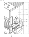
- FIGS. 1 to 8 an air humidification and purification device 100 will be described with reference to FIGS. 1 to 8 according to an embodiment of the present invention.
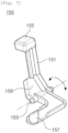
- FIG. 6 is a perspective diagram illustrating a flow path regulating member 180 provided in an air humidification and purification device 100 according to an embodiment of the present invention.
- FIG. 7 is a perspective diagram illustrating a water supply regulating member 150 illustrated in FIG. 4 .
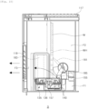
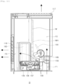
- FIG. 8 is diagrams illustrating the air humidification and purification device 100 illustrated in FIG. 1 , where the lower portion is a longitudinal cross-sectional diagram illustrating a central portion, and the upper portion is a longitudinal cross-sectional diagram illustrating in a state in which a water container 130 is removed, taken along line A-A' in FIG. 1 .
- the discharge port 116 may be divided into a humidified air discharge port 118 through which air flowing in from the suction port 115 is discharged through the air purification filter 120 and the humidification member 160 described later, and a purified air discharge port 117 through which air is discharged without passing through the humidification member 160.
- the suction port 115 may be installed on a plurality of surfaces among the front, rear, left, and right surfaces of the housing 110 so as to suction air in various directions, and the installation positions of the humidified air discharge port 118 and the purified air discharge port 117 and the number of the humidified air discharge port 118 and the purified air discharge port 117 may also be varied.
- the air purification filter 120 is provided within the housing 110 and is configured to filter (purify) air flowing in from the suction port 115, and may be disposed on the rear end of the suction port 115. Also, the air purification filter 120 may be installed on the front end of the blowing part 170 such that air flowing in from the suction port 115 may be filtered by the air purification filter 120 and may flow into the blowing part 170.
- the air purification filter 120 may be configured in a rectangular shape corresponding to the shape and cross-sectional area of the air flow path on the rear end of the suction port 115, and accordingly, the entire air flowing in through the suction port 115 of the housing 110 may pass through the air purification filter 120.
- the shape of the air purification filter 120 is not limited to the above-described rectangular shape, and various types of known filters may be used.
- the air purification filter 120 may be configured as a three-dimensional filter having a circular or angular cross-sectional surface and having a space (hollow) formed therein.
- the air purification filter 120 may be selected from among filters having various shapes and functions, and the type of the air purification filter 120, the number of the air purification filter 120, the shape of the air purification filter 120 are not limited to the example illustrated in FIG. 8 , and may be varied.
- the water container 130 may include a water container body 131 for accommodating water for humidification therein, and includes a water supply valve member 135 opening and closing to allow water accommodated in the water container body 131 to be discharged.
- the water container 130 may be configured to be separated from the air humidification and purification device 100 so as to easily fill the water container body 131 with water.
- the water container body 131 of the water container 130 may be configured to form a portion of the exterior of the housing 110 and may be separated from the housing 110, but an example embodiment thereof is not limited thereto.
- the water supply valve member 135 may be installed in a cap structure screwed to an inlet (an inlet port) of the water container body 131.
- the water supply valve member 135 may include an opening/closing part 136 elastically supported by an elastic means (a spring), and may have a mechanical valve structure in which a closed state is maintained while the opening/closing part 136 is not pressed, and an open state is maintained while the opening/closing part 136 is pressed.
- the water supply valve member 135 may be generally used for the water container 130 of a general humidifier, and thus, a detailed description thereof will not be provided.
- the water tank unit 140 may be installed within the housing 110 and may accommodate water supplied from the water container 130 by opening the water supply valve member 135.
- the water tank unit 140 may include a water tank body 141 for accommodating water, and a water tank cover 145 for covering at least a portion of the upper portion of the water tank body 141. Also, an opening cover 143 for blocking the through-hole 112b (in FIG. 2 ) when the water tank unit 140 is mounted on the opening 113 of the housing 110 may be installed on the upper side of the water tank cover 145.
- the water tank cover 145 may include a humidification member mounting opening 146 for mounting the humidification member 160, a water tank seating part 148 on which the water container 130 is seated, and an installation groove 147 in which the water supply regulating member 150 described later is installed.
- the water tank unit 140 may be installed to be separated from the housing 110 by sliding while the water container 130 is separated from the housing 110.
- the humidification member (humidification filter) 160 may perform humidification by vaporization (by blowing) using water supplied to the water tank body 141 of the water tank unit 140, and may be installed adjacent to the humidified air discharge port 118 and disposed side by side with the front of the housing 110
- the humidification member 160 may be disposed on the rear end of the blowing part 170 on the air flow path, and accordingly, air flowing by operation of the blowing part 170 may be humidified while passing through the humidification member 160, and may be discharged through the humidified air discharge port 118.
- the air purification filter 120 is disposed on the front end of the blowing part 170 and the humidification member 160 is disposed on the rear end of the blowing part 170, when only an air purifying function is performed, the flowing of air filtered in the air purification filter 120 to the humidification member 160 may be limited, and accordingly, air purifying efficiency may increase. Also, even when the blowing fan provided in the blowing part 170 is driven even at a relatively low RPM and low power, a sufficient amount of discharge may be secured and noise may be reduced. Further, when humidification is performed in the blowing part 170 the flow path switching of the flow path regulating member 180 described later, as the entire discharged air flows toward the humidification member 160, the humidification efficiency may increase.
- the humidification member 160 may be configured to have a material having excellent hygroscopicity or a shape so as to sufficiently absorb water contained in the water tank unit 140.
- the humidification member 160 may be configured to be immersed in water accommodated in the water tank body 141 as illustrated in FIGS. 2 to 4 .
- the humidification member 160 is not limited to the above-described structure, and when humidification by vaporization is possible, various known vaporization-based humidification structures such as a rotating disk-shaped humidification member may be used.
- the humidification member 160 may be mounted on and separated from the water tank unit 140 through the humidification member mounting opening 146 formed in the water tank cover 145. Also, the humidification member 160 may be separated from the housing 110 by sliding while the water container 130 is separated from the housing 110 and is mounted on the water tank unit 140.
- the blowing part 170 is configured to provide blowing force to allow air flowing in from the suction port 115 to flow to the discharge port 116 (117 and 118) via the air flow path part F1, F2, and F3 formed between the suction port 115 and the discharge port 116 (117 and 118).
- the air flow path part F1, F2, and F3 may include a blowing flow path F1 disposed on the discharge port side of the blowing part 170, a purification flow path F2 through which air from the blowing flow path F1 flows to the purified air discharge port 117, and a humidification flow path F3 which air from the blowing flow path F1 flows to the humidified air discharge port 118.
- the specific air flow path of the air flow path part F1, F2, and F3 may be varied depending on the positions of the suction port 115 and the discharge port 116 (117 and 118), and the suction/discharge position and direction of the blowing part 170.
- the blowing part 170 may include a blowing fan for flowing air, and a fan motor for driving the blowing fan, similarly to a general blowing device used in an air purifier.
- the blowing part 170 may be disposed on the rear of the air purification filter 120 with respect to the air flow path and may have a structure in which air is suctioned from one side of the blowing part 170, but the installation position and the suctioning structure of the blowing part 170 is not limited to the examples illustrated in FIG. 8 and may be varied.
- the blowing fan provided in the blowing part 170 may have a double suction structure in which air is suctioned from both sides of the blowing part.
- the flow path regulating member 180 is disposed to be able to rotate in the air flow path portion F1, F2, and F3, and may regulate the air flow to the discharge port 116 (117 and 118).
- the flow path regulating member 180 may switch the flow path such that air flowing through the air flow path part F1, F2, and F3 to pass through at least one of the humidified air discharge port 118 and the purified air discharge port 117.
- the flow path regulating member 180 may be configured to rotate between the purification mode position (see FIG. 9 ) in which air filtered by the air purification filter 120 and discharged from the blowing part 170 may flow to the purified air discharge port 117 via the purification flow path F2, and a humidification mode position (see FIG. 10 ) in which air from the blowing part 170 may flow to the humidified air discharge port 118 via the humidification flow path F3. That is, air purified through the air purification filter 120 may pass through the humidification member 160 and may be discharged through the humidified air discharge port 118 in a humidified state when the flow path regulating member 180 is in the humidification mode position illustrated in FIG. 10 , and when the flow path regulating member 180 is in the purification mode position illustrated in FIG. 9 , air may be discharged through the purified air discharge port 117 without passing through the humidification member 160.
- the flow path regulating member 180 may be disposed in a third position (a drying mode position) disposed between the purification mode position and the humidification mode position (see FIG. 11 ), and in the case, air from the blowing part 170 may be branched into the purification flow path F2 and the humidification flow path F3 and may flow to both the purified air discharge port 117 and the humidified air discharge port 118.
- the flow path regulating member 180 includes a body part 181 configured to cross the air flow path part F1, F2, and F3 to open and close at least a portion of the air flow path part F1, F2, and F3, and a pressing part 185 configured to pressurize the water supply regulating member 150 described later as the body part 181 rotates around the rotary shaft part 183.
- the flow path regulating member 180 is configured to be rotated by a driving part M including a motor and other components. Accordingly, by controlling the driving part M by the control part C, the flow path regulating member 180 may rotate between the purification mode position and the humidification mode position.
- the opening and closing of the water supply valve member 135 provided in the water container 130 is configured to be performed by rotation of the flow path regulating member 180.
- the flow path regulating member 180 may be configured to open the water supply valve member 135 provided in the water container 130 such that water may be supplied from the water container 130 to the water tank unit 140.
- the opening and closing of the water supply valve member 135 provided in the water container 130 is performed by rotation of the flow path regulating member 180, the water supply from the water container 130 to the water tank unit 140 may be efficiently blocked, and a driving means for supplying water to the water tank unit 140 may not be necessary.
- the air humidification and purification device 100 may further include a water supply regulating member 150 installed in the water tank unit 140 and operating to open and close the water supply valve member 135 provided in the water container 130
- the flow path regulating member 180 may be configured to pressurize the water supply regulating member 150 to open the water supply valve member 135 provided in the water container 130.
- the water supply regulating member 150 may be installed in the water tank cover 145 of the water tank unit 140 as illustrated in FIGS. 3 and 4 .
- the water supply regulating member 150 may include a body part 151, a contact part 155 disposed on one side of the body part 151 and able to be pressed by the pressing part 185 of the flow path regulating member 180, a pushing part 157 formed on the other side of the body part 151 and able to pressurize the water supply valve member 135 of the water container 130, and a rotary shaft part 153 disposed between the contact part 155 and the pushing part 157 and coupled to the installation groove 147 formed in the water tank cover 145.
- the water supply regulating member 150 may be configured to be perform seesaw movement with respect to the rotary shaft part 153 (see the arrow in FIG. 3 ). Also, referring to FIGS. 3 , 5 , 8 and 10 , when the pressing part 185 of the flow path regulating member 180 pressurizes the contact part 155 downwardly, the pushing part 157 may move upwardly with respect to the rotary shaft part 153, such that the water supply valve member 135 may be opened. That is, as illustrated in FIG.
- the opening/closing part 136 provided in the water supply valve member 135 may move upwardly, such that the space into which water may flow may be formed around the opening/closing part 136, and accordingly, water may be supplied from the water container 130 to the water tank unit 140.
- the installation groove 147 of the water tank cover 145 in which the water supply regulating member 150 is installed may be configured as a groove in which, while the water supply regulating member 150 is installed in the water tank cover 145, the contact part 155 side (upper side) may be opened and the pushing part 157 side (lower side) may be closed. Accordingly, the water supply regulating member 150 may maintain a stable position without being separated from the installation groove 147 even when the pressing part 185 of the flow path regulating member 180 pressurizes the contact part 155 of the water supply regulating member 150.
- the housing 110 may include an opening 113 in which the water container 130 is installed, and a partition 112 for partitioning the air flow path part F1, F2, and F3.
- the water supply regulating member 150 may be disposed in the opening 113 which may be the outer side of the partition 112, and the flow regulating member 180 may be disposed in the air flow path part F1, F2, and F3 which may be the inner side of the partition 112.
- the pressing part 185 of the flow path regulating member 180 may be exposed to the opening 113 through the through-hole 112a formed in the partition 112 to pressurize the contact part 155 of the water supply regulating member 150 disposed in the opening 113.
- the humidification member 160 is also disposed in the humidification flow path F3 of the air flow path part F1, F2, and F3 which may be the inner side of the partition 112, another through-hole 112b may be formed in the partition 112 to allow the water tank unit 140 on which the humidification member 160 is mounted may be disposed in the humidification path F3, and an opening cover 143 may be provided on the water tank unit 140 to close the through-hole 112b.
- the contact part 155 of the water supply regulating member 150 when the water tank unit 140 is installed in the housing 110, when the contact part 155 of the water supply regulating member 150 is lifted upwardly, the contact part 155 may be in contact with and may interfere with the side surface of the pressing part 185 of the flow path regulating member 180. In the case, the water tank unit 140 may not be properly installed, such that water may not be supplied from the water container 130, which may be problematic.
- the contact part 155 side may be inclined in a downward direction with respect to the rotary shaft part 153 while the water supply regulating member 150 is installed on the water tank cover 145.
- the water supply regulating member 150 may be configured to include a weight part 159 for adding weight to one side of the body part 151, that is, the contact part 155 side. Accordingly, when the water tank unit 140 is separated from the housing 110, the contact part 155 may be inclined downwardly by the weight of the weight part 159. Therefore, even when the water tank unit 140 is mounted on the housing 110, the contact part 155 of the water supply regulating member 150 may not be interfered with the pressing part 185 of the flow path regulating member 180, such that the water tank unit 140 may be stably installed.
- the air humidification and purification device 100 may further include a control part C (in FIG. 6 ) for controlling operation of the flow path regulating member 180 and the blowing part 170.
- the control part C may regulate the rotational position of the flow path regulating member 180 in response to the purification mode and the humidification mode and may drive the blowing part 170.
- the controller C may move the flow path regulating member 180 to the drying mode position (the third position) disposed between the humidification mode position and the purification mode position, such that the humidification member 160 is dried after the humidification ends.
- the blowing part 170 may be driven to dry water absorbed in the humidification member 160 and/or water contained in the water tank unit 140.
- the drying mode may be performed for a predetermined period of time required for drying the humidification member 160 and/or the water tank unit 140 through time control, but an example embodiment thereof is not limited thereto.
- the flow path regulating member 180 may be disposed in the vertical direction to open the purification flow path F2 of the air flow path part F1, F2, and F3.
- the air blown from the blowing part 170 may be discharged through the purified air discharge port 117 via the open purification flow path F2 due to flow resistance of the humidification member 160 installed in the humidification flow path F3.
- the pressing part 185 of the flow path regulating member 180 may be spaced apart from the contact part 155 of the water supply regulating member 150, such that the pushing part 157 of the flow path regulating member 180 may not pressurize the water supply valve member 135. Accordingly, the opening/closing part 136 provided in the water supply valve member 135 may maintain a closed state by the elastic force of the elastic means (the spring), and water may not be supplied from the water container 130 to the water tank unit 140.
- the flow path regulating member 180 may be disposed in a direction of crossing the transverse cross-sectional surface of the purification flow path F2, such as, for example, in an oblique direction, to close the purification flow path F2 of the air flow path part F1, F2, and F3. That is, the flow path regulating member 180 may be disposed such that the upper end of the body part 181 may be inclined toward the humidified air discharge port 118.
- the upper end of the body part 181 of the flow path regulating member 180 may be adjacent to a partition wall W and the lower end may be adjacent to the opposite side of the partition wall W, such that the air flow to the purification flow path F2 may be blocked and air flowing through the air flow path part may flow into the humidification path F3 through the through-hole WH formed in the partition wall W. Accordingly, the air blown from the blowing part 170 may be humidified through the humidification member 160 and discharged externally of the housing 110 through the humidified air discharge port 118.
- the pressing part 185 of the flow path regulating member 180 may be in contact with the contact part 155 of the water supply regulating member 150 and may pressurize the contact part 155, the contact part 155 of the water supply regulating member 150 may move in a downward direction with respect to the rotary shaft part 153, and the pushing part 157 of the water supply regulating member 150 may move in the upward direction with respect to the rotary shaft part 153. Accordingly, the pushing part 157 of the flow path regulating member 180 may pressurize the opening/closing part 136 of the water supply valve member 135 upwardly, such that the opening/closing part 136 may move upwardly. Accordingly, the opening/closing part 136 may be opened, such that water may be supplied from the water container 130 to the water tank unit 140.
- the flow path regulating member 180 may have the third position (the drying mode position) disposed between the purification mode position and the humidification mode position.
- the third position the drying mode position
- the humidification member 160 and/or the water tank unit 140 may be dried.
- the inclination angle of the flow path regulating member 180 in the vertical direction may be smaller than the inclination angle in the vertical direction in the humidification mode position in FIG. 10 .
- the upper end of the flow path regulating member 180 may be slightly spaced apart from the partition wall W and the lower end may be slightly spaced apart from the opposite wall of the partition wall W, such that some air may flow into the purification flow path F2 and some air may flow into the humidification path F3 through the through-hole WH formed in the partition wall W.
- the humidification member 160 may be dried.
- the humidification member 160 may be configured to absorb moisture of the water contained in the water tank unit 140, and in the case, water contained in the water tank unit 140 may be dried according to the drying of the humidification member 160.
- the opening/closing part 136 provided in the water supply valve member 135 may be closed by the elastic force of the elastic means (spring), and the water supply from the water container 130 to the water tank unit 140 may be blocked.
- the position of the flow path regulating member 180 in the drying mode may be determined to sufficiently secure the amount of air blown into the humidification flow path F3.
- the position of the flow path regulating member 180 in the drying mode may slightly rotate from the humidification mode position such that the contact between the pressing part 185 and the contact part 155 of the water supply regulating member 150 may be released and the opening/closing part 136 may be closed.
- the controller C may move the flow path regulating member 180 from the humidification mode position to the drying mode position between the humidification mode position and the purification mode position after the humidification mode ends, such that the humidification member 160 may be dried.
- the blowing part 170 may be driven to dry the water absorbed in the humidification member 160 and/or the water contained in the water tank unit 140.
- the drying mode may be performed not only after the humidification mode ends, and the drying mode may be performed by a user selection or may be performed after the purification mode ends.
- the drying mode may be performed for a predetermined period of time necessary for drying the humidification member 160 and/or the water tank unit 140 through time control, but an example embodiment thereof is not limited thereto.
- the humidification mode in which water is supplied by a simple manipulation of rotating the flow path regulating member 180 and the purification mode in which humidification is not performed may be easily implemented, and the drying mode for drying the humidification member 160 may also be easily performed.
- water may be supplied to the water tank unit 140 only when the flow path regulating member 180 is in the humidification mode position, and water supply to the water tank unit 140 may be blocked in the purification mode and the drying mode position, such that, by performing the drying mode, moisture present in the water tank unit 140 and/or the humidification member 160 may be removed. Accordingly, contamination and bacterial generation in the water tank unit 140 and/or the humidification member 160 may be significantly reduced.
Landscapes
- Engineering & Computer Science (AREA)
- Chemical & Material Sciences (AREA)
- Combustion & Propulsion (AREA)
- Mechanical Engineering (AREA)
- General Engineering & Computer Science (AREA)
- Chemical Kinetics & Catalysis (AREA)
- Signal Processing (AREA)
- Physics & Mathematics (AREA)
- Fuzzy Systems (AREA)
- Mathematical Physics (AREA)
- Air Humidification (AREA)
Claims (15)
- Vorrichtung zur Luftbefeuchtung und -reinigung (100), umfassend:ein Gehäuse (110) mit einem Ansauganschluss (115), durch den Luft angesaugt wird, und einem Ausstoßanschluss (116), durch den Luft ausgestoßen wird;ein Blasteil (170), das in dem Gehäuse (110) vorgesehen ist und eine Blaskraft bereitstellt, damit Luft, die von dem Ansauganschluss (115) einströmt, zu dem Ausstoßanschluss (116) strömen kann;einen Luftreinigungsfilter (120), der in dem Gehäuse (110) angeordnet ist und Luft filtert, die von dem Ansauganschluss (115) einströmt;einen Wasserbehälter (130), der in dem Gehäuse (110) vorgesehen ist;eine Wassertankeinheit (140) zum Aufnehmen von Wasser aus dem Wasserbehälter (130);ein Befeuchtungselement (160) zum Durchführen einer Befeuchtung unter Verwendung von Wasser, das der Wassertankeinheit (140) zugeführt wird;einen Luftströmungspfadteil (F1, F2, F3), der zwischen dem Ansauganschluss (115) und dem Ausstoßanschluss (116) ausgebildet ist und in dem Luft strömt, die von dem Ansauganschluss (115) strömt;ein Strömungspfad-Regulierungselement (180), das drehbar in dem Luftströmungspfadteil (F1, F2, F3) angeordnet ist; undein Antriebsteil (M) zum Bereitstellen einer Drehkraft für das Strömungspfad-Regulierungselement (180),wobei der Wasserbehälter (130) ein Wasserzufuhrventilelement (135) beinhaltet, das sich öffnet und schließt, damit das darin enthaltene Wasser ausgestoßen werden kann,wobei das Strömungspfad-Regulierungselement (180) umfasst:ein Drehwellenteil (183), das als Drehzentrum ausgebildet ist; undein Körperteil (181), das sich integral mit dem Drehwellenteil (183) dreht und so konfiguriert ist, dass es den Luftströmungspfadteil (F1, F2, F3) kreuzt, um zumindest einen Abschnitt des Luftströmungspfadteils (F1, F2, F3) zu öffnen und zu schließen;dadurch gekennzeichnet, dassdas Strömungspfad-Regulierungselement (180) weiterhin ein Druckteil (185) umfasst, das sich einstückig mit dem Drehwellenteil (183) dreht und eine Druckkraft zum Öffnen des Wasserzufuhrventilelements (135) bereitstellt, und dass sich bei Drehung des Strömungspfad-Regulierungselements (180) die Richtung des Luftstroms in dem Luftströmungspfadteil (F1, F2, F3) durch das Körperteil (181) ändert und sich das Wasserzufuhrventilelement (135) durch das Druckteil (185) öffnet und schließt.
- Vorrichtung zur Luftbefeuchtung und -reinigung (100) nach Anspruch 1, wobei der Ausstoßanschluss (116) einen Ausstoßanschluss (118) für befeuchtete Luft, durch die Luft, die von dem Ansauganschluss (115) einströmt, durch den Luftreinigungsfilter (120) und das Befeuchtungselement (160) ausgestoßen wird, und einen Ausstoßanschluss (117) für gereinigte Luft, durch den Luft ausgestoßen wird, ohne durch das Befeuchtungselement (160) hindurchzutreten, umfasst.
- Vorrichtung zur Luftbefeuchtung und -reinigung (100) nach Anspruch 2, wobei das Strömungspfad-Regulierungselement (180) einen Strömungspfad so umschaltet, dass Luft, die durch den Luftströmungspfadteil (F1, F2, F3) strömt, durch zumindest einen des Ausstoßanschlusses (118) für befeuchtete Luft und des Ausstoßanschlusses (117) für gereinigte Luft ausgestoßen wird.
- Vorrichtung zur Luftbefeuchtung und -reinigung (100) nach Anspruch 3, wobei das Strömungspfad-Regulierungselement (180) eine Reinigungsmodusposition, in der Luft, die durch den Luftströmungspfadteil (F1, F2, F3) strömt, durch den Ausstoßanschluss (117) für gereinigte Luft ausgestoßen wird, und eine Befeuchtungsmodusposition, in der Luft durch den Ausstoßanschluss (118) für befeuchtete Luft ausgestoßen wird, aufweist.
- Vorrichtung zur Luftbefeuchtung und -reinigung (100) nach Anspruch 4, wobei das Strömungspfad-Regulierungselement (180) so konfiguriert ist, dass es das Wasserzufuhrventilelement (135) in der Befeuchtungsmodusposition öffnet.
- Vorrichtung zur Luftbefeuchtung und -reinigung (100) nach Anspruch 4, wobei das Strömungspfad-Regulierungselement (180) weiterhin eine dritte Position beinhaltet, die zwischen der Reinigungsmodusposition und der Befeuchtungsmodusposition so angeordnet ist, dass Luft, die durch den Luftströmungspfadteil (F1, F2, F3) strömt, durch den Ausstoßanschluss (117) für gereinigte Luft und den Ausstoßanschluss (118) für befeuchtete Luft ausgestoßen wird.
- Vorrichtung zur Luftbefeuchtung und -reinigung (100) nach Anspruch 6, weiterhin umfassend:ein Steuerteil (C) zum Steuern des Antriebs des Strömungspfad-Regulierungselements (180) und des Blasteils (170),wobei das Steuerteil (C) das Strömungspfad-Regulierungselement (180) in die dritte Position bewegt, so dass das Befeuchtungselement (160) nach dem Ende der Befeuchtung getrocknet wird.
- Vorrichtung zur Luftbefeuchtung und -reinigung (100) nach einem der Ansprüche 1 bis 7, ferner umfassend:ein Wasserzufuhr-Regulierungselement (150), das in der Wassertankeinheit (140) installiert ist und zum Öffnen und Schließen des Wasserzufuhrventilelements (135) dient,wobei das Strömungspfad-Regulierungselement (180) das Wasserzufuhrventilelement (135) öffnet, indem es das Wasserzufuhr-Regulierungselements (150) mit Druck beaufschlagt.
- Vorrichtung zur Luftbefeuchtung und -reinigung (100) nach Anspruch 8,wobei die Wassertankeinheit (140) einen Wassertankkörper (141) zur Aufnahme von Wasser darin und eine Wassertankabdeckung (145) zum Abdecken zumindest eines Abschnitts eines oberen Abschnitts des Wassertankkörpers (141) umfasst, undwobei das Wasserzufuhr-Regulierungselement (150) an der Wassertankabdeckung (145) installiert ist.
- Vorrichtung zur Luftbefeuchtung und -reinigung (100) nach Anspruch 9, wobei das Wasserzufuhr-Regulierungselement (150) ein Körperteil (151), ein Kontaktteil (155), das auf einer Seite des Körperteils (151) ausgebildet ist und durch das Strömungspfad-Regulierungselement (180) gedrückt wird, ein Druckteil (157), das auf der anderen Seite des Körperteils (151) ausgebildet ist und das Wasserzufuhrventilelement (135) mit Druck beaufschlagt, und ein Drehwellenteil (153), das zwischen dem Kontaktteil (155) und dem Druckteil (157) angeordnet ist und mit einer Installationsnut (147) gekoppelt ist, die in der Wassertankabdeckung (145) ausgebildet ist, umfasst.
- Vorrichtung zur Luftbefeuchtung und -reinigung (100) nach Anspruch 10,wobei das Wasserzufuhr-Regulierungselement (150) so konfiguriert ist, dass es eine Wippbewegung in Bezug auf das rotierende Wellenteil (183) ausführen kann, undwobei sich, wenn das Strömungsregulierungselement (180) das Kontaktteil (155) nach unten mit Druck beaufschlagt, das Druckteil (157) nach oben bewegt und das Wasserzufuhrventilelement (135) öffnet.
- Vorrichtung zur Luftbefeuchtung und -reinigung (100) nach Anspruch 10, wobei das Wasserzufuhr-Regulierungselement (150) ein Gewichtsteil (159) zum Hinzufügen von Gewicht zu einer Seite des Körperteils (151) umfasst, so dass die Seite des Kontaktteils (155) in einem Zustand, in dem das Wasserzufuhr-Regulierungselement (150) in der Wassertankabdeckung (145) installiert ist, in Bezug auf das Drehwellenteil (153) nach unten geneigt ist.
- Vorrichtung zur Luftbefeuchtung und -reinigung (100) nach Anspruch 10, wobei die Installationsnut (147) als Nut konfiguriert ist, bei der die Seite des Kontaktteils (155) geöffnet ist und die Seite des Druckteils (157) geschlossen ist, in einem Zustand, in dem das Wasserzufuhr-Regulierungselement (150) an der Wassertankabdeckung (145) installiert ist.
- Vorrichtung zur Luftbefeuchtung und -reinigung (100) nach Anspruch 13, wobei das Gehäuse (110) eine Öffnung, in der der Wasserbehälter (130) installiert ist, und eine Trennwand (112) zum Unterteilen des Luftströmungspfadteils (F1, F2, F3) darin umfasst, wobei das Wasserzufuhr-Regulierungselement (150) in der Öffnung angeordnet ist, und wobei das Druckteil (157) des Strömungspfad-Regulierungselements (180) durch ein in der Trennwand (112) ausgebildetes Durchgangsloch (112a) zu der Öffnung hin freiliegt, um das Kontaktteil (155) mit Druck zu beaufschlagen.
- Vorrichtung zur Luftbefeuchtung und -reinigung (100) nach einem der Ansprüche 1 bis 7, wobei die Wassertankeinheit (140) und das Befeuchtungselement (160) so installiert sind, dass sie durch Verschieben von dem Gehäuse (110) getrennt werden können, während der Wasserbehälter (130) von dem Gehäuse (110) getrennt ist.
Applications Claiming Priority (2)
| Application Number | Priority Date | Filing Date | Title |
|---|---|---|---|
| KR1020190071805A KR102838131B1 (ko) | 2019-06-17 | 2019-06-17 | 가습청정기 |
| PCT/KR2020/007657 WO2020256354A1 (ko) | 2019-06-17 | 2020-06-12 | 가습청정기 |
Publications (4)
| Publication Number | Publication Date |
|---|---|
| EP3971487A1 EP3971487A1 (de) | 2022-03-23 |
| EP3971487A4 EP3971487A4 (de) | 2022-07-27 |
| EP3971487C0 EP3971487C0 (de) | 2025-04-09 |
| EP3971487B1 true EP3971487B1 (de) | 2025-04-09 |
Family
ID=74037343
Family Applications (1)
| Application Number | Title | Priority Date | Filing Date |
|---|---|---|---|
| EP20826869.8A Active EP3971487B1 (de) | 2019-06-17 | 2020-06-12 | Vorrichtung zur luftbefeuchtung und -reinigung |
Country Status (6)
| Country | Link |
|---|---|
| US (1) | US12013150B2 (de) |
| EP (1) | EP3971487B1 (de) |
| JP (1) | JP7519922B2 (de) |
| KR (1) | KR102838131B1 (de) |
| CN (1) | CN113994153B (de) |
| WO (1) | WO2020256354A1 (de) |
Families Citing this family (24)
| Publication number | Priority date | Publication date | Assignee | Title |
|---|---|---|---|---|
| KR102300503B1 (ko) * | 2018-12-28 | 2021-09-09 | 코웨이 주식회사 | 유로제어부재를 포함하는 공기 청정기 |
| KR102340052B1 (ko) | 2019-01-03 | 2021-12-16 | 코웨이 주식회사 | 가습기 |
| KR102838131B1 (ko) * | 2019-06-17 | 2025-07-25 | 코웨이 주식회사 | 가습청정기 |
| USD1012257S1 (en) * | 2020-12-01 | 2024-01-23 | Coway Co., Ltd. | Air purifier |
| USD1013136S1 (en) * | 2020-12-07 | 2024-01-30 | Coway Co., Ltd. | Air purifier |
| JP1705212S (ja) * | 2020-12-11 | 2022-01-17 | 空気清浄機 | |
| JP1718767S (ja) * | 2021-04-13 | 2022-07-01 | 加湿器 | |
| USD1057917S1 (en) * | 2021-05-10 | 2025-01-14 | Sharkninja Operating Llc | Air purifier |
| USD1004067S1 (en) * | 2021-05-11 | 2023-11-07 | Shenzhen Airtok Technology Co., Ltd. | Air cleaner |
| USD1051318S1 (en) * | 2021-06-04 | 2024-11-12 | Shenzhen JISU Technology Co., Ltd | Humidifier |
| USD1057918S1 (en) * | 2021-06-23 | 2025-01-14 | Sharkninja Operating Llc | Air purifier |
| USD986398S1 (en) * | 2021-07-20 | 2023-05-16 | Shenzhen Airtok Technology Co., Ltd. | Air cleaner |
| USD1042774S1 (en) * | 2021-07-29 | 2024-09-17 | Shenzhen Chenbei Technology Co., Ltd. | Air purifier |
| USD1023266S1 (en) * | 2021-08-09 | 2024-04-16 | Winix Inc. | Air cleaner |
| USD1031959S1 (en) * | 2021-12-15 | 2024-06-18 | Samsung Electronics Co., Ltd. | Air purifier |
| USD1047107S1 (en) * | 2022-07-18 | 2024-10-15 | Shenzhen Puremate Technology Co., Ltd. | Air purifier |
| USD1047108S1 (en) * | 2022-08-23 | 2024-10-15 | Zhongshan Konlon Electrical Technology Co., Ltd | Air purifier |
| USD1004063S1 (en) * | 2023-02-20 | 2023-11-07 | Shenzhen Qianyan Technology LTD | Humidifier |
| CN117029172B (zh) * | 2023-08-31 | 2025-10-03 | 爱源(厦门)电子有限公司 | 空气净化加湿器 |
| CN117598629B (zh) * | 2023-12-27 | 2025-08-22 | 临沂市东旭塑料科技有限公司 | 一种臭味净化马桶盖 |
| USD1051324S1 (en) * | 2024-07-10 | 2024-11-12 | Foshan Shunde Zhuotai Hardware Products Co., Ltd. | Pet air purifier |
| USD1051323S1 (en) * | 2024-07-10 | 2024-11-12 | Foshan Shunde Zhuotai Hardware Products Co., Ltd. | Pet air purifier |
| USD1054007S1 (en) * | 2024-09-13 | 2024-12-10 | Haomin Ruan | Air purifier |
| USD1085383S1 (en) * | 2024-11-05 | 2025-07-22 | Foshan Shunde Mengsai Information Technology Consulting Service Center | Pet air purifier |
Family Cites Families (64)
| Publication number | Priority date | Publication date | Assignee | Title |
|---|---|---|---|---|
| US3361415A (en) * | 1965-09-30 | 1968-01-02 | Donald F. Lane | Demineralizer control system |
| JPH01139489U (de) | 1988-03-18 | 1989-09-22 | ||
| JPH0380230U (de) * | 1989-11-30 | 1991-08-16 | ||
| US5368784A (en) * | 1993-10-08 | 1994-11-29 | American Metal Products Co. | Scoop humidifier |
| US6053482A (en) * | 1997-01-31 | 2000-04-25 | Holmes Products Corp. | Humidifier including a water filtration device |
| US5857350A (en) * | 1997-04-14 | 1999-01-12 | Johnson; Robert Edwin | Evaporative cooling device |
| US6427984B1 (en) * | 2000-08-11 | 2002-08-06 | Hamilton Beach/Proctor-Silex, Inc. | Evaporative humidifier |
| US6805336B2 (en) * | 2002-03-04 | 2004-10-19 | Emerson Electric Co. | Self-sealing dispensing valve for humidifier water bottles |
| JP3776373B2 (ja) | 2002-04-12 | 2006-05-17 | 株式会社コロナ | 加湿器 |
| US6945519B2 (en) * | 2003-09-25 | 2005-09-20 | Sunbeam Products, Inc. | Microorganism-resistant humidifier |
| JP4683985B2 (ja) * | 2005-04-13 | 2011-05-18 | 三菱電機株式会社 | 加湿機 |
| WO2008015851A1 (fr) * | 2006-08-03 | 2008-02-07 | Sharp Kabushiki Kaisha | Épurateur d'air |
| JP4368367B2 (ja) * | 2006-08-03 | 2009-11-18 | シャープ株式会社 | 空気清浄機 |
| US20080093750A1 (en) * | 2006-10-18 | 2008-04-24 | Zhijing Wang | Dual inlet water tank for a humidifier |
| US8313569B2 (en) * | 2006-11-20 | 2012-11-20 | Winiamando Inc. | Air washer having humidifying function |
| JP5130805B2 (ja) | 2007-07-04 | 2013-01-30 | パナソニック株式会社 | 加湿装置 |
| KR100988441B1 (ko) * | 2007-12-04 | 2010-10-18 | 웅진코웨이주식회사 | 공기 청정 및 가습 장치 |
| EP2072921B1 (de) * | 2007-12-04 | 2017-04-19 | Woongjin Coway Co., Ltd. | Vorrichtung zum Reinigen und Befeuchten von Luft |
| JP2010276296A (ja) * | 2009-05-29 | 2010-12-09 | Sharp Corp | 加湿装置 |
| KR20110092928A (ko) * | 2010-02-11 | 2011-08-18 | 최송휘 | 가습기 |
| KR101765663B1 (ko) * | 2010-06-24 | 2017-08-23 | 코웨이 주식회사 | 공기 청정기 및 그 운전 방법 |
| JP2012052699A (ja) * | 2010-08-31 | 2012-03-15 | Sanyo Electric Co Ltd | 加湿器 |
| JP5621547B2 (ja) * | 2010-11-26 | 2014-11-12 | パナソニック株式会社 | 加湿機能付空気清浄機 |
| US8931762B2 (en) * | 2010-12-23 | 2015-01-13 | Lg Electronics Inc. | Air conditioner |
| KR20120101788A (ko) | 2011-03-07 | 2012-09-17 | 웅진코웨이주식회사 | 가습장치 |
| KR20120113026A (ko) * | 2011-04-04 | 2012-10-12 | 웅진코웨이주식회사 | 가습장치 |
| JP5959334B2 (ja) * | 2011-07-15 | 2016-08-02 | シャープ株式会社 | 加湿装置 |
| KR101276044B1 (ko) * | 2012-01-18 | 2013-06-20 | 이인영 | 자동 건조기능을 갖는 가습기 |
| KR102046476B1 (ko) * | 2012-02-29 | 2019-11-19 | 웅진코웨이 주식회사 | 누수 방지가 가능한 가습 장치 |
| US8701701B2 (en) * | 2012-09-25 | 2014-04-22 | Chin-Cheng Huang | Float switch of a humidifier |
| JP5953196B2 (ja) * | 2012-09-26 | 2016-07-20 | シャープ株式会社 | 加湿装置 |
| US9360227B2 (en) * | 2013-03-15 | 2016-06-07 | Helen Of Troy Limited | Removable top fill tank |
| KR102287262B1 (ko) * | 2014-05-13 | 2021-08-06 | 삼성전자주식회사 | 기화식 가습기 및 그 제어방법 |
| CN203964241U (zh) * | 2014-05-30 | 2014-11-26 | 广东松下环境系统有限公司 | 加湿装置 |
| KR102337161B1 (ko) * | 2014-11-26 | 2021-12-08 | 삼성전자주식회사 | 공기조화장치 |
| KR102466276B1 (ko) * | 2015-04-16 | 2022-11-11 | 삼성전자주식회사 | 가습기 및 가전기기 |
| PL3093567T3 (pl) * | 2015-05-12 | 2018-01-31 | Venta Luftwaescher Gmbh | Zasobnik filtra, walec i nawilżacz powietrza |
| KR101973644B1 (ko) * | 2015-10-30 | 2019-08-26 | 엘지전자 주식회사 | 가습청정장치 |
| WO2017138718A1 (ko) * | 2016-02-12 | 2017-08-17 | 주식회사 경동나비엔 | 공기조화기와 그 제어방법 |
| JP6699963B2 (ja) * | 2016-02-29 | 2020-05-27 | シャープ株式会社 | 加湿機 |
| KR102582102B1 (ko) * | 2016-05-11 | 2023-09-22 | 에스케이매직 주식회사 | 누수 방지 가습기 |
| CN107676908A (zh) * | 2016-08-02 | 2018-02-09 | 3M创新有限公司 | 一种加湿装置、一种空气净化器和一种家用电器 |
| KR102664148B1 (ko) * | 2016-12-22 | 2024-05-10 | 코웨이 주식회사 | 가습형 공기청정기 |
| CN206310047U (zh) * | 2016-12-23 | 2017-07-07 | 陈祎芸 | 一种加湿器的下水控制装置 |
| JP6998501B2 (ja) * | 2017-03-27 | 2022-02-10 | パナソニックIpマネジメント株式会社 | 除湿装置 |
| KR20190001334A (ko) * | 2017-06-27 | 2019-01-04 | 코웨이 주식회사 | 선택적으로 가습 기능과 공기 청정 기능을 수행할 수 있는 가습 공기 청정기 |
| KR101893533B1 (ko) | 2017-09-04 | 2018-08-30 | 주식회사 에스앤아이 | 제빙장치 |
| CN109425071B (zh) * | 2017-09-04 | 2024-09-10 | 深圳市联创电器实业有限公司 | 一种自动控制下水装置及其加湿器 |
| DE202019100292U1 (de) * | 2018-01-19 | 2019-05-09 | Lg Electronics Inc. | Luftreiniger |
| KR102186444B1 (ko) * | 2018-01-19 | 2020-12-04 | 엘지전자 주식회사 | 가습 공기청정기 |
| US11971070B2 (en) * | 2018-03-16 | 2024-04-30 | Lg Electronics Inc. | Indoor unit for an air conditioner |
| CN108870615B (zh) * | 2018-05-17 | 2020-09-11 | 安徽工程大学 | 一种具有香薰功能的加湿器 |
| US10168064B1 (en) * | 2018-07-13 | 2019-01-01 | Zhongshan Titan Arts & Crafts Co., Ltd. | Ultrasonic humidifier |
| CN108825803B (zh) * | 2018-08-27 | 2024-06-04 | 珠海格力电器股份有限公司 | 出水阀结构及包括其的加湿器 |
| CN108825804B (zh) * | 2018-08-27 | 2023-08-15 | 珠海格力电器股份有限公司 | 出水阀结构及包括其的加湿器 |
| KR102340052B1 (ko) * | 2019-01-03 | 2021-12-16 | 코웨이 주식회사 | 가습기 |
| CN110186139B (zh) * | 2019-05-29 | 2025-03-21 | 深圳市晨北科技有限公司 | 一种防水装置及加湿器 |
| KR102838131B1 (ko) * | 2019-06-17 | 2025-07-25 | 코웨이 주식회사 | 가습청정기 |
| JP7252867B2 (ja) * | 2019-09-13 | 2023-04-05 | シャープ株式会社 | 空気調和機 |
| KR102770051B1 (ko) * | 2019-12-10 | 2025-02-21 | 삼성전자주식회사 | 가습기 |
| KR20210120518A (ko) * | 2020-03-27 | 2021-10-07 | 코웨이 주식회사 | 가습기 |
| KR20210144336A (ko) * | 2020-05-22 | 2021-11-30 | 코웨이 주식회사 | 공기 청정기 |
| CN113154576B (zh) * | 2021-05-31 | 2025-06-24 | 爱源(厦门)电子有限公司 | 一种上浮子式加湿器 |
| CN118382475A (zh) * | 2021-09-02 | 2024-07-23 | 赖安·雷德福德 | 带有改进阀的换气系统 |
-
2019
- 2019-06-17 KR KR1020190071805A patent/KR102838131B1/ko active Active
-
2020
- 2020-06-12 WO PCT/KR2020/007657 patent/WO2020256354A1/ko not_active Ceased
- 2020-06-12 US US17/618,719 patent/US12013150B2/en active Active
- 2020-06-12 CN CN202080044004.3A patent/CN113994153B/zh active Active
- 2020-06-12 JP JP2020572778A patent/JP7519922B2/ja active Active
- 2020-06-12 EP EP20826869.8A patent/EP3971487B1/de active Active
Also Published As
| Publication number | Publication date |
|---|---|
| KR102838131B1 (ko) | 2025-07-25 |
| EP3971487C0 (de) | 2025-04-09 |
| US20220243934A1 (en) | 2022-08-04 |
| CN113994153B (zh) | 2024-02-13 |
| EP3971487A4 (de) | 2022-07-27 |
| JP7519922B2 (ja) | 2024-07-22 |
| EP3971487A1 (de) | 2022-03-23 |
| CN113994153A (zh) | 2022-01-28 |
| KR20200144003A (ko) | 2020-12-28 |
| WO2020256354A1 (ko) | 2020-12-24 |
| JP2022537852A (ja) | 2022-08-31 |
| US12013150B2 (en) | 2024-06-18 |
Similar Documents
| Publication | Publication Date | Title |
|---|---|---|
| EP3971487B1 (de) | Vorrichtung zur luftbefeuchtung und -reinigung | |
| KR100988441B1 (ko) | 공기 청정 및 가습 장치 | |
| KR101782838B1 (ko) | 공기조화기와 그 제어방법 | |
| JP7438149B2 (ja) | 加湿器 | |
| KR20110001624A (ko) | 가습 장치 및 이를 구비한 공기 청정기 | |
| CN216953357U (zh) | 空调器的换气装置和具有其的空调器 | |
| JP2021042935A (ja) | 空気調和機 | |
| EP3904774B1 (de) | Luftreiniger mit strömungswegregler | |
| JP7712760B2 (ja) | 加湿器 | |
| KR20190001334A (ko) | 선택적으로 가습 기능과 공기 청정 기능을 수행할 수 있는 가습 공기 청정기 | |
| JP2010002155A (ja) | 空気調和装置 | |
| KR101240123B1 (ko) | 가습 공기청정기 | |
| KR20210085452A (ko) | 가습기 및 그 제어방법 | |
| JP5126341B2 (ja) | 空気清浄機 | |
| JP4752862B2 (ja) | 空気清浄機 | |
| KR101403010B1 (ko) | 가습 제습 복합기 | |
| KR100352430B1 (ko) | 실내 제습 시스템과 실내 가습 시스템을 갖는 공기조화시스템 및 그 운전 제어방법 | |
| US12492830B2 (en) | Humidifier | |
| KR20110001356A (ko) | 가습형 공기 청정기 | |
| JP7682629B2 (ja) | 加湿器及びその制御方法 | |
| RU2797492C1 (ru) | Увлажнитель | |
| KR102714762B1 (ko) | 가습필터의 건조가 가능한 공기청정기 | |
| KR101403012B1 (ko) | 가습 제습 복합기의 유로 구조 | |
| KR101817096B1 (ko) | 가습장치 | |
| KR20130029692A (ko) | 가습 제습 복합기 제어방법 |
Legal Events
| Date | Code | Title | Description |
|---|---|---|---|
| STAA | Information on the status of an ep patent application or granted ep patent |
Free format text: STATUS: THE INTERNATIONAL PUBLICATION HAS BEEN MADE |
|
| PUAI | Public reference made under article 153(3) epc to a published international application that has entered the european phase |
Free format text: ORIGINAL CODE: 0009012 |
|
| STAA | Information on the status of an ep patent application or granted ep patent |
Free format text: STATUS: REQUEST FOR EXAMINATION WAS MADE |
|
| 17P | Request for examination filed |
Effective date: 20211216 |
|
| AK | Designated contracting states |
Kind code of ref document: A1 Designated state(s): AL AT BE BG CH CY CZ DE DK EE ES FI FR GB GR HR HU IE IS IT LI LT LU LV MC MK MT NL NO PL PT RO RS SE SI SK SM TR |
|
| A4 | Supplementary search report drawn up and despatched |
Effective date: 20220627 |
|
| RIC1 | Information provided on ipc code assigned before grant |
Ipc: F24F 13/20 20060101ALI20220621BHEP Ipc: F24F 13/10 20060101ALI20220621BHEP Ipc: F24F 11/65 20180101ALI20220621BHEP Ipc: F24F 8/80 20210101ALI20220621BHEP Ipc: F24F 6/00 20060101ALI20220621BHEP Ipc: F24F 13/14 20060101ALI20220621BHEP Ipc: F24F 11/00 20180101ALI20220621BHEP Ipc: F24F 3/16 20210101ALI20220621BHEP Ipc: F24F 6/04 20060101AFI20220621BHEP Ipc: F24F 8/108 20210101ALI20220621BHEP |
|
| DAV | Request for validation of the european patent (deleted) | ||
| DAX | Request for extension of the european patent (deleted) | ||
| GRAP | Despatch of communication of intention to grant a patent |
Free format text: ORIGINAL CODE: EPIDOSNIGR1 |
|
| STAA | Information on the status of an ep patent application or granted ep patent |
Free format text: STATUS: GRANT OF PATENT IS INTENDED |
|
| RIC1 | Information provided on ipc code assigned before grant |
Ipc: F24F 8/108 20210101ALI20241028BHEP Ipc: F24F 13/20 20060101ALI20241028BHEP Ipc: F24F 13/10 20060101ALI20241028BHEP Ipc: F24F 11/65 20180101ALI20241028BHEP Ipc: F24F 8/80 20210101ALI20241028BHEP Ipc: F24F 6/00 20060101ALI20241028BHEP Ipc: F24F 13/14 20060101ALI20241028BHEP Ipc: F24F 11/00 20180101ALI20241028BHEP Ipc: F24F 3/16 20210101ALI20241028BHEP Ipc: F24F 6/04 20060101AFI20241028BHEP |
|
| INTG | Intention to grant announced |
Effective date: 20241114 |
|
| GRAS | Grant fee paid |
Free format text: ORIGINAL CODE: EPIDOSNIGR3 |
|
| GRAA | (expected) grant |
Free format text: ORIGINAL CODE: 0009210 |
|
| STAA | Information on the status of an ep patent application or granted ep patent |
Free format text: STATUS: THE PATENT HAS BEEN GRANTED |
|
| AK | Designated contracting states |
Kind code of ref document: B1 Designated state(s): AL AT BE BG CH CY CZ DE DK EE ES FI FR GB GR HR HU IE IS IT LI LT LU LV MC MK MT NL NO PL PT RO RS SE SI SK SM TR |
|
| REG | Reference to a national code |
Ref country code: GB Ref legal event code: FG4D |
|
| REG | Reference to a national code |
Ref country code: CH Ref legal event code: EP |
|
| REG | Reference to a national code |
Ref country code: DE Ref legal event code: R096 Ref document number: 602020049228 Country of ref document: DE |
|
| REG | Reference to a national code |
Ref country code: IE Ref legal event code: FG4D |
|
| U01 | Request for unitary effect filed |
Effective date: 20250409 |
|
| U07 | Unitary effect registered |
Designated state(s): AT BE BG DE DK EE FI FR IT LT LU LV MT NL PT RO SE SI Effective date: 20250416 |
|
| U20 | Renewal fee for the european patent with unitary effect paid |
Year of fee payment: 6 Effective date: 20250606 |
|
| PG25 | Lapsed in a contracting state [announced via postgrant information from national office to epo] |
Ref country code: ES Free format text: LAPSE BECAUSE OF FAILURE TO SUBMIT A TRANSLATION OF THE DESCRIPTION OR TO PAY THE FEE WITHIN THE PRESCRIBED TIME-LIMIT Effective date: 20250409 |
|
| PG25 | Lapsed in a contracting state [announced via postgrant information from national office to epo] |
Ref country code: NO Free format text: LAPSE BECAUSE OF FAILURE TO SUBMIT A TRANSLATION OF THE DESCRIPTION OR TO PAY THE FEE WITHIN THE PRESCRIBED TIME-LIMIT Effective date: 20250709 Ref country code: GR Free format text: LAPSE BECAUSE OF FAILURE TO SUBMIT A TRANSLATION OF THE DESCRIPTION OR TO PAY THE FEE WITHIN THE PRESCRIBED TIME-LIMIT Effective date: 20250710 |
|
| PG25 | Lapsed in a contracting state [announced via postgrant information from national office to epo] |
Ref country code: PL Free format text: LAPSE BECAUSE OF FAILURE TO SUBMIT A TRANSLATION OF THE DESCRIPTION OR TO PAY THE FEE WITHIN THE PRESCRIBED TIME-LIMIT Effective date: 20250409 |
|
| PG25 | Lapsed in a contracting state [announced via postgrant information from national office to epo] |
Ref country code: HR Free format text: LAPSE BECAUSE OF FAILURE TO SUBMIT A TRANSLATION OF THE DESCRIPTION OR TO PAY THE FEE WITHIN THE PRESCRIBED TIME-LIMIT Effective date: 20250409 |
|
| PG25 | Lapsed in a contracting state [announced via postgrant information from national office to epo] |
Ref country code: RS Free format text: LAPSE BECAUSE OF FAILURE TO SUBMIT A TRANSLATION OF THE DESCRIPTION OR TO PAY THE FEE WITHIN THE PRESCRIBED TIME-LIMIT Effective date: 20250709 |
|
| PG25 | Lapsed in a contracting state [announced via postgrant information from national office to epo] |
Ref country code: IS Free format text: LAPSE BECAUSE OF FAILURE TO SUBMIT A TRANSLATION OF THE DESCRIPTION OR TO PAY THE FEE WITHIN THE PRESCRIBED TIME-LIMIT Effective date: 20250809 |