EP3971397B1 - Particulate filter - Google Patents
Particulate filter Download PDFInfo
- Publication number
- EP3971397B1 EP3971397B1 EP20833399.7A EP20833399A EP3971397B1 EP 3971397 B1 EP3971397 B1 EP 3971397B1 EP 20833399 A EP20833399 A EP 20833399A EP 3971397 B1 EP3971397 B1 EP 3971397B1
- Authority
- EP
- European Patent Office
- Prior art keywords
- layer
- partition
- inlet
- outlet
- particulate filter
- Prior art date
- Legal status (The legal status is an assumption and is not a legal conclusion. Google has not performed a legal analysis and makes no representation as to the accuracy of the status listed.)
- Active
Links
Images

Classifications
-
- F—MECHANICAL ENGINEERING; LIGHTING; HEATING; WEAPONS; BLASTING
- F01—MACHINES OR ENGINES IN GENERAL; ENGINE PLANTS IN GENERAL; STEAM ENGINES
- F01N—GAS-FLOW SILENCERS OR EXHAUST APPARATUS FOR MACHINES OR ENGINES IN GENERAL; GAS-FLOW SILENCERS OR EXHAUST APPARATUS FOR INTERNAL-COMBUSTION ENGINES
- F01N3/00—Exhaust or silencing apparatus having means for purifying, rendering innocuous, or otherwise treating exhaust
- F01N3/02—Exhaust or silencing apparatus having means for purifying, rendering innocuous, or otherwise treating exhaust for cooling, or for removing solid constituents of, exhaust
- F01N3/021—Exhaust or silencing apparatus having means for purifying, rendering innocuous, or otherwise treating exhaust for cooling, or for removing solid constituents of, exhaust by means of filters
- F01N3/022—Exhaust or silencing apparatus having means for purifying, rendering innocuous, or otherwise treating exhaust for cooling, or for removing solid constituents of, exhaust by means of filters characterised by specially adapted filtering structure, e.g. honeycomb, mesh or fibrous
-
- B—PERFORMING OPERATIONS; TRANSPORTING
- B01—PHYSICAL OR CHEMICAL PROCESSES OR APPARATUS IN GENERAL
- B01D—SEPARATION
- B01D46/00—Filters or filtering processes specially modified for separating dispersed particles from gases or vapours
- B01D46/24—Particle separators, e.g. dust precipitators, using rigid hollow filter bodies
- B01D46/2403—Particle separators, e.g. dust precipitators, using rigid hollow filter bodies characterised by the physical shape or structure of the filtering element
- B01D46/2418—Honeycomb filters
- B01D46/2451—Honeycomb filters characterized by the geometrical structure, shape, pattern or configuration or parameters related to the geometry of the structure
- B01D46/2474—Honeycomb filters characterized by the geometrical structure, shape, pattern or configuration or parameters related to the geometry of the structure of the walls along the length of the honeycomb
-
- B—PERFORMING OPERATIONS; TRANSPORTING
- B01—PHYSICAL OR CHEMICAL PROCESSES OR APPARATUS IN GENERAL
- B01D—SEPARATION
- B01D46/00—Filters or filtering processes specially modified for separating dispersed particles from gases or vapours
- B01D46/66—Regeneration of the filtering material or filter elements inside the filter
- B01D46/80—Chemical processes for the removal of the retained particles, e.g. by burning
- B01D46/82—Chemical processes for the removal of the retained particles, e.g. by burning with catalysts
-
- B—PERFORMING OPERATIONS; TRANSPORTING
- B01—PHYSICAL OR CHEMICAL PROCESSES OR APPARATUS IN GENERAL
- B01D—SEPARATION
- B01D53/00—Separation of gases or vapours; Recovering vapours of volatile solvents from gases; Chemical or biological purification of waste gases, e.g. engine exhaust gases, smoke, fumes, flue gases, aerosols
- B01D53/34—Chemical or biological purification of waste gases
- B01D53/92—Chemical or biological purification of waste gases of engine exhaust gases
- B01D53/94—Chemical or biological purification of waste gases of engine exhaust gases by catalytic processes
- B01D53/944—Simultaneously removing carbon monoxide, hydrocarbons or carbon making use of oxidation catalysts
-
- B—PERFORMING OPERATIONS; TRANSPORTING
- B01—PHYSICAL OR CHEMICAL PROCESSES OR APPARATUS IN GENERAL
- B01J—CHEMICAL OR PHYSICAL PROCESSES, e.g. CATALYSIS OR COLLOID CHEMISTRY; THEIR RELEVANT APPARATUS
- B01J21/00—Catalysts comprising the elements, oxides, or hydroxides of magnesium, boron, aluminium, carbon, silicon, titanium, zirconium, or hafnium
- B01J21/02—Boron or aluminium; Oxides or hydroxides thereof
- B01J21/04—Alumina
-
- B—PERFORMING OPERATIONS; TRANSPORTING
- B01—PHYSICAL OR CHEMICAL PROCESSES OR APPARATUS IN GENERAL
- B01J—CHEMICAL OR PHYSICAL PROCESSES, e.g. CATALYSIS OR COLLOID CHEMISTRY; THEIR RELEVANT APPARATUS
- B01J23/00—Catalysts comprising metals or metal oxides or hydroxides, not provided for in group B01J21/00
- B01J23/02—Catalysts comprising metals or metal oxides or hydroxides, not provided for in group B01J21/00 of the alkali- or alkaline earth metals or beryllium
-
- B—PERFORMING OPERATIONS; TRANSPORTING
- B01—PHYSICAL OR CHEMICAL PROCESSES OR APPARATUS IN GENERAL
- B01J—CHEMICAL OR PHYSICAL PROCESSES, e.g. CATALYSIS OR COLLOID CHEMISTRY; THEIR RELEVANT APPARATUS
- B01J23/00—Catalysts comprising metals or metal oxides or hydroxides, not provided for in group B01J21/00
- B01J23/38—Catalysts comprising metals or metal oxides or hydroxides, not provided for in group B01J21/00 of noble metals
- B01J23/40—Catalysts comprising metals or metal oxides or hydroxides, not provided for in group B01J21/00 of noble metals of the platinum group metals
- B01J23/42—Platinum
-
- B—PERFORMING OPERATIONS; TRANSPORTING
- B01—PHYSICAL OR CHEMICAL PROCESSES OR APPARATUS IN GENERAL
- B01J—CHEMICAL OR PHYSICAL PROCESSES, e.g. CATALYSIS OR COLLOID CHEMISTRY; THEIR RELEVANT APPARATUS
- B01J23/00—Catalysts comprising metals or metal oxides or hydroxides, not provided for in group B01J21/00
- B01J23/38—Catalysts comprising metals or metal oxides or hydroxides, not provided for in group B01J21/00 of noble metals
- B01J23/40—Catalysts comprising metals or metal oxides or hydroxides, not provided for in group B01J21/00 of noble metals of the platinum group metals
- B01J23/44—Palladium
-
- B—PERFORMING OPERATIONS; TRANSPORTING
- B01—PHYSICAL OR CHEMICAL PROCESSES OR APPARATUS IN GENERAL
- B01J—CHEMICAL OR PHYSICAL PROCESSES, e.g. CATALYSIS OR COLLOID CHEMISTRY; THEIR RELEVANT APPARATUS
- B01J23/00—Catalysts comprising metals or metal oxides or hydroxides, not provided for in group B01J21/00
- B01J23/38—Catalysts comprising metals or metal oxides or hydroxides, not provided for in group B01J21/00 of noble metals
- B01J23/40—Catalysts comprising metals or metal oxides or hydroxides, not provided for in group B01J21/00 of noble metals of the platinum group metals
- B01J23/46—Ruthenium, rhodium, osmium or iridium
- B01J23/464—Rhodium
-
- B—PERFORMING OPERATIONS; TRANSPORTING
- B01—PHYSICAL OR CHEMICAL PROCESSES OR APPARATUS IN GENERAL
- B01J—CHEMICAL OR PHYSICAL PROCESSES, e.g. CATALYSIS OR COLLOID CHEMISTRY; THEIR RELEVANT APPARATUS
- B01J23/00—Catalysts comprising metals or metal oxides or hydroxides, not provided for in group B01J21/00
- B01J23/38—Catalysts comprising metals or metal oxides or hydroxides, not provided for in group B01J21/00 of noble metals
- B01J23/54—Catalysts comprising metals or metal oxides or hydroxides, not provided for in group B01J21/00 of noble metals combined with metals, oxides or hydroxides provided for in groups B01J23/02 - B01J23/36
- B01J23/56—Platinum group metals
- B01J23/58—Platinum group metals with alkali- or alkaline earth metals
-
- B—PERFORMING OPERATIONS; TRANSPORTING
- B01—PHYSICAL OR CHEMICAL PROCESSES OR APPARATUS IN GENERAL
- B01J—CHEMICAL OR PHYSICAL PROCESSES, e.g. CATALYSIS OR COLLOID CHEMISTRY; THEIR RELEVANT APPARATUS
- B01J35/00—Catalysts, in general, characterised by their form or physical properties
- B01J35/19—Catalysts containing parts with different compositions
-
- B—PERFORMING OPERATIONS; TRANSPORTING
- B01—PHYSICAL OR CHEMICAL PROCESSES OR APPARATUS IN GENERAL
- B01J—CHEMICAL OR PHYSICAL PROCESSES, e.g. CATALYSIS OR COLLOID CHEMISTRY; THEIR RELEVANT APPARATUS
- B01J35/00—Catalysts, in general, characterised by their form or physical properties
- B01J35/50—Catalysts, in general, characterised by their form or physical properties characterised by their shape or configuration
- B01J35/56—Foraminous structures having flow-through passages or channels, e.g. grids or three-dimensional monoliths
-
- B—PERFORMING OPERATIONS; TRANSPORTING
- B01—PHYSICAL OR CHEMICAL PROCESSES OR APPARATUS IN GENERAL
- B01J—CHEMICAL OR PHYSICAL PROCESSES, e.g. CATALYSIS OR COLLOID CHEMISTRY; THEIR RELEVANT APPARATUS
- B01J35/00—Catalysts, in general, characterised by their form or physical properties
- B01J35/60—Catalysts, in general, characterised by their form or physical properties characterised by their surface properties or porosity
- B01J35/64—Pore diameter
- B01J35/657—Pore diameter larger than 1000 nm
-
- B—PERFORMING OPERATIONS; TRANSPORTING
- B01—PHYSICAL OR CHEMICAL PROCESSES OR APPARATUS IN GENERAL
- B01J—CHEMICAL OR PHYSICAL PROCESSES, e.g. CATALYSIS OR COLLOID CHEMISTRY; THEIR RELEVANT APPARATUS
- B01J37/00—Processes, in general, for preparing catalysts; Processes, in general, for activation of catalysts
- B01J37/0009—Use of binding agents; Moulding; Pressing; Powdering; Granulating; Addition of materials ameliorating the mechanical properties of the product catalyst
- B01J37/0027—Powdering
- B01J37/0045—Drying a slurry, e.g. spray drying
-
- B—PERFORMING OPERATIONS; TRANSPORTING
- B01—PHYSICAL OR CHEMICAL PROCESSES OR APPARATUS IN GENERAL
- B01J—CHEMICAL OR PHYSICAL PROCESSES, e.g. CATALYSIS OR COLLOID CHEMISTRY; THEIR RELEVANT APPARATUS
- B01J37/00—Processes, in general, for preparing catalysts; Processes, in general, for activation of catalysts
- B01J37/02—Impregnation, coating or precipitation
- B01J37/0215—Coating
-
- F—MECHANICAL ENGINEERING; LIGHTING; HEATING; WEAPONS; BLASTING
- F01—MACHINES OR ENGINES IN GENERAL; ENGINE PLANTS IN GENERAL; STEAM ENGINES
- F01N—GAS-FLOW SILENCERS OR EXHAUST APPARATUS FOR MACHINES OR ENGINES IN GENERAL; GAS-FLOW SILENCERS OR EXHAUST APPARATUS FOR INTERNAL-COMBUSTION ENGINES
- F01N3/00—Exhaust or silencing apparatus having means for purifying, rendering innocuous, or otherwise treating exhaust
- F01N3/02—Exhaust or silencing apparatus having means for purifying, rendering innocuous, or otherwise treating exhaust for cooling, or for removing solid constituents of, exhaust
- F01N3/021—Exhaust or silencing apparatus having means for purifying, rendering innocuous, or otherwise treating exhaust for cooling, or for removing solid constituents of, exhaust by means of filters
- F01N3/022—Exhaust or silencing apparatus having means for purifying, rendering innocuous, or otherwise treating exhaust for cooling, or for removing solid constituents of, exhaust by means of filters characterised by specially adapted filtering structure, e.g. honeycomb, mesh or fibrous
- F01N3/0222—Exhaust or silencing apparatus having means for purifying, rendering innocuous, or otherwise treating exhaust for cooling, or for removing solid constituents of, exhaust by means of filters characterised by specially adapted filtering structure, e.g. honeycomb, mesh or fibrous the structure being monolithic, e.g. honeycombs
-
- F—MECHANICAL ENGINEERING; LIGHTING; HEATING; WEAPONS; BLASTING
- F01—MACHINES OR ENGINES IN GENERAL; ENGINE PLANTS IN GENERAL; STEAM ENGINES
- F01N—GAS-FLOW SILENCERS OR EXHAUST APPARATUS FOR MACHINES OR ENGINES IN GENERAL; GAS-FLOW SILENCERS OR EXHAUST APPARATUS FOR INTERNAL-COMBUSTION ENGINES
- F01N3/00—Exhaust or silencing apparatus having means for purifying, rendering innocuous, or otherwise treating exhaust
- F01N3/02—Exhaust or silencing apparatus having means for purifying, rendering innocuous, or otherwise treating exhaust for cooling, or for removing solid constituents of, exhaust
- F01N3/021—Exhaust or silencing apparatus having means for purifying, rendering innocuous, or otherwise treating exhaust for cooling, or for removing solid constituents of, exhaust by means of filters
- F01N3/033—Exhaust or silencing apparatus having means for purifying, rendering innocuous, or otherwise treating exhaust for cooling, or for removing solid constituents of, exhaust by means of filters in combination with other devices
- F01N3/035—Exhaust or silencing apparatus having means for purifying, rendering innocuous, or otherwise treating exhaust for cooling, or for removing solid constituents of, exhaust by means of filters in combination with other devices with catalytic reactors
-
- F—MECHANICAL ENGINEERING; LIGHTING; HEATING; WEAPONS; BLASTING
- F01—MACHINES OR ENGINES IN GENERAL; ENGINE PLANTS IN GENERAL; STEAM ENGINES
- F01N—GAS-FLOW SILENCERS OR EXHAUST APPARATUS FOR MACHINES OR ENGINES IN GENERAL; GAS-FLOW SILENCERS OR EXHAUST APPARATUS FOR INTERNAL-COMBUSTION ENGINES
- F01N3/00—Exhaust or silencing apparatus having means for purifying, rendering innocuous, or otherwise treating exhaust
- F01N3/08—Exhaust or silencing apparatus having means for purifying, rendering innocuous, or otherwise treating exhaust for rendering innocuous
- F01N3/10—Exhaust or silencing apparatus having means for purifying, rendering innocuous, or otherwise treating exhaust for rendering innocuous by thermal or catalytic conversion of noxious components of exhaust
- F01N3/101—Three-way catalysts
-
- B—PERFORMING OPERATIONS; TRANSPORTING
- B01—PHYSICAL OR CHEMICAL PROCESSES OR APPARATUS IN GENERAL
- B01D—SEPARATION
- B01D2255/00—Catalysts
- B01D2255/10—Noble metals or compounds thereof
- B01D2255/102—Platinum group metals
- B01D2255/1023—Palladium
-
- B—PERFORMING OPERATIONS; TRANSPORTING
- B01—PHYSICAL OR CHEMICAL PROCESSES OR APPARATUS IN GENERAL
- B01D—SEPARATION
- B01D2255/00—Catalysts
- B01D2255/20—Metals or compounds thereof
- B01D2255/204—Alkaline earth metals
- B01D2255/2042—Barium
-
- B—PERFORMING OPERATIONS; TRANSPORTING
- B01—PHYSICAL OR CHEMICAL PROCESSES OR APPARATUS IN GENERAL
- B01D—SEPARATION
- B01D2255/00—Catalysts
- B01D2255/90—Physical characteristics of catalysts
- B01D2255/902—Multilayered catalyst
- B01D2255/9022—Two layers
-
- B—PERFORMING OPERATIONS; TRANSPORTING
- B01—PHYSICAL OR CHEMICAL PROCESSES OR APPARATUS IN GENERAL
- B01D—SEPARATION
- B01D2255/00—Catalysts
- B01D2255/90—Physical characteristics of catalysts
- B01D2255/908—O2-storage component incorporated in the catalyst
-
- B—PERFORMING OPERATIONS; TRANSPORTING
- B01—PHYSICAL OR CHEMICAL PROCESSES OR APPARATUS IN GENERAL
- B01D—SEPARATION
- B01D2255/00—Catalysts
- B01D2255/90—Physical characteristics of catalysts
- B01D2255/915—Catalyst supported on particulate filters
- B01D2255/9155—Wall flow filters
-
- B—PERFORMING OPERATIONS; TRANSPORTING
- B01—PHYSICAL OR CHEMICAL PROCESSES OR APPARATUS IN GENERAL
- B01D—SEPARATION
- B01D2258/00—Sources of waste gases
- B01D2258/01—Engine exhaust gases
- B01D2258/014—Stoichiometric gasoline engines
-
- B—PERFORMING OPERATIONS; TRANSPORTING
- B01—PHYSICAL OR CHEMICAL PROCESSES OR APPARATUS IN GENERAL
- B01D—SEPARATION
- B01D2279/00—Filters adapted for separating dispersed particles from gases or vapours specially modified for specific uses
- B01D2279/30—Filters adapted for separating dispersed particles from gases or vapours specially modified for specific uses for treatment of exhaust gases from IC Engines
-
- B—PERFORMING OPERATIONS; TRANSPORTING
- B01—PHYSICAL OR CHEMICAL PROCESSES OR APPARATUS IN GENERAL
- B01D—SEPARATION
- B01D53/00—Separation of gases or vapours; Recovering vapours of volatile solvents from gases; Chemical or biological purification of waste gases, e.g. engine exhaust gases, smoke, fumes, flue gases, aerosols
- B01D53/34—Chemical or biological purification of waste gases
- B01D53/92—Chemical or biological purification of waste gases of engine exhaust gases
- B01D53/94—Chemical or biological purification of waste gases of engine exhaust gases by catalytic processes
- B01D53/9404—Removing only nitrogen compounds
- B01D53/9409—Nitrogen oxides
- B01D53/9413—Processes characterised by a specific catalyst
- B01D53/9418—Processes characterised by a specific catalyst for removing nitrogen oxides by selective catalytic reduction [SCR] using a reducing agent in a lean exhaust gas
-
- F—MECHANICAL ENGINEERING; LIGHTING; HEATING; WEAPONS; BLASTING
- F01—MACHINES OR ENGINES IN GENERAL; ENGINE PLANTS IN GENERAL; STEAM ENGINES
- F01N—GAS-FLOW SILENCERS OR EXHAUST APPARATUS FOR MACHINES OR ENGINES IN GENERAL; GAS-FLOW SILENCERS OR EXHAUST APPARATUS FOR INTERNAL-COMBUSTION ENGINES
- F01N2250/00—Combinations of different methods of purification
- F01N2250/02—Combinations of different methods of purification filtering and catalytic conversion
-
- F—MECHANICAL ENGINEERING; LIGHTING; HEATING; WEAPONS; BLASTING
- F01—MACHINES OR ENGINES IN GENERAL; ENGINE PLANTS IN GENERAL; STEAM ENGINES
- F01N—GAS-FLOW SILENCERS OR EXHAUST APPARATUS FOR MACHINES OR ENGINES IN GENERAL; GAS-FLOW SILENCERS OR EXHAUST APPARATUS FOR INTERNAL-COMBUSTION ENGINES
- F01N2330/00—Structure of catalyst support or particle filter
- F01N2330/06—Ceramic, e.g. monoliths
-
- F—MECHANICAL ENGINEERING; LIGHTING; HEATING; WEAPONS; BLASTING
- F01—MACHINES OR ENGINES IN GENERAL; ENGINE PLANTS IN GENERAL; STEAM ENGINES
- F01N—GAS-FLOW SILENCERS OR EXHAUST APPARATUS FOR MACHINES OR ENGINES IN GENERAL; GAS-FLOW SILENCERS OR EXHAUST APPARATUS FOR INTERNAL-COMBUSTION ENGINES
- F01N2370/00—Selection of materials for exhaust purification
- F01N2370/22—Selection of materials for exhaust purification used in non-catalytic purification apparatus
- F01N2370/24—Zeolitic material
-
- F—MECHANICAL ENGINEERING; LIGHTING; HEATING; WEAPONS; BLASTING
- F01—MACHINES OR ENGINES IN GENERAL; ENGINE PLANTS IN GENERAL; STEAM ENGINES
- F01N—GAS-FLOW SILENCERS OR EXHAUST APPARATUS FOR MACHINES OR ENGINES IN GENERAL; GAS-FLOW SILENCERS OR EXHAUST APPARATUS FOR INTERNAL-COMBUSTION ENGINES
- F01N2510/00—Surface coverings
- F01N2510/06—Surface coverings for exhaust purification, e.g. catalytic reaction
- F01N2510/063—Surface coverings for exhaust purification, e.g. catalytic reaction zeolites
-
- F—MECHANICAL ENGINEERING; LIGHTING; HEATING; WEAPONS; BLASTING
- F01—MACHINES OR ENGINES IN GENERAL; ENGINE PLANTS IN GENERAL; STEAM ENGINES
- F01N—GAS-FLOW SILENCERS OR EXHAUST APPARATUS FOR MACHINES OR ENGINES IN GENERAL; GAS-FLOW SILENCERS OR EXHAUST APPARATUS FOR INTERNAL-COMBUSTION ENGINES
- F01N2510/00—Surface coverings
- F01N2510/06—Surface coverings for exhaust purification, e.g. catalytic reaction
- F01N2510/068—Surface coverings for exhaust purification, e.g. catalytic reaction characterised by the distribution of the catalytic coatings
- F01N2510/0682—Surface coverings for exhaust purification, e.g. catalytic reaction characterised by the distribution of the catalytic coatings having a discontinuous, uneven or partially overlapping coating of catalytic material, e.g. higher amount of material upstream than downstream or vice versa
-
- F—MECHANICAL ENGINEERING; LIGHTING; HEATING; WEAPONS; BLASTING
- F01—MACHINES OR ENGINES IN GENERAL; ENGINE PLANTS IN GENERAL; STEAM ENGINES
- F01N—GAS-FLOW SILENCERS OR EXHAUST APPARATUS FOR MACHINES OR ENGINES IN GENERAL; GAS-FLOW SILENCERS OR EXHAUST APPARATUS FOR INTERNAL-COMBUSTION ENGINES
- F01N2510/00—Surface coverings
- F01N2510/06—Surface coverings for exhaust purification, e.g. catalytic reaction
- F01N2510/068—Surface coverings for exhaust purification, e.g. catalytic reaction characterised by the distribution of the catalytic coatings
- F01N2510/0684—Surface coverings for exhaust purification, e.g. catalytic reaction characterised by the distribution of the catalytic coatings having more than one coating layer, e.g. multi-layered coatings
-
- F—MECHANICAL ENGINEERING; LIGHTING; HEATING; WEAPONS; BLASTING
- F01—MACHINES OR ENGINES IN GENERAL; ENGINE PLANTS IN GENERAL; STEAM ENGINES
- F01N—GAS-FLOW SILENCERS OR EXHAUST APPARATUS FOR MACHINES OR ENGINES IN GENERAL; GAS-FLOW SILENCERS OR EXHAUST APPARATUS FOR INTERNAL-COMBUSTION ENGINES
- F01N3/00—Exhaust or silencing apparatus having means for purifying, rendering innocuous, or otherwise treating exhaust
- F01N3/02—Exhaust or silencing apparatus having means for purifying, rendering innocuous, or otherwise treating exhaust for cooling, or for removing solid constituents of, exhaust
- F01N3/021—Exhaust or silencing apparatus having means for purifying, rendering innocuous, or otherwise treating exhaust for cooling, or for removing solid constituents of, exhaust by means of filters
- F01N3/023—Exhaust or silencing apparatus having means for purifying, rendering innocuous, or otherwise treating exhaust for cooling, or for removing solid constituents of, exhaust by means of filters using means for regenerating the filters, e.g. by burning trapped particles
- F01N3/025—Exhaust or silencing apparatus having means for purifying, rendering innocuous, or otherwise treating exhaust for cooling, or for removing solid constituents of, exhaust by means of filters using means for regenerating the filters, e.g. by burning trapped particles using fuel burner or by adding fuel to exhaust
- F01N3/0253—Exhaust or silencing apparatus having means for purifying, rendering innocuous, or otherwise treating exhaust for cooling, or for removing solid constituents of, exhaust by means of filters using means for regenerating the filters, e.g. by burning trapped particles using fuel burner or by adding fuel to exhaust adding fuel to exhaust gases
-
- F—MECHANICAL ENGINEERING; LIGHTING; HEATING; WEAPONS; BLASTING
- F01—MACHINES OR ENGINES IN GENERAL; ENGINE PLANTS IN GENERAL; STEAM ENGINES
- F01N—GAS-FLOW SILENCERS OR EXHAUST APPARATUS FOR MACHINES OR ENGINES IN GENERAL; GAS-FLOW SILENCERS OR EXHAUST APPARATUS FOR INTERNAL-COMBUSTION ENGINES
- F01N3/00—Exhaust or silencing apparatus having means for purifying, rendering innocuous, or otherwise treating exhaust
- F01N3/08—Exhaust or silencing apparatus having means for purifying, rendering innocuous, or otherwise treating exhaust for rendering innocuous
- F01N3/10—Exhaust or silencing apparatus having means for purifying, rendering innocuous, or otherwise treating exhaust for rendering innocuous by thermal or catalytic conversion of noxious components of exhaust
- F01N3/24—Exhaust or silencing apparatus having means for purifying, rendering innocuous, or otherwise treating exhaust for rendering innocuous by thermal or catalytic conversion of noxious components of exhaust characterised by constructional aspects of converting apparatus
- F01N3/28—Construction of catalytic reactors
- F01N3/2882—Catalytic reactors combined or associated with other devices, e.g. exhaust silencers or other exhaust purification devices
-
- F—MECHANICAL ENGINEERING; LIGHTING; HEATING; WEAPONS; BLASTING
- F01—MACHINES OR ENGINES IN GENERAL; ENGINE PLANTS IN GENERAL; STEAM ENGINES
- F01N—GAS-FLOW SILENCERS OR EXHAUST APPARATUS FOR MACHINES OR ENGINES IN GENERAL; GAS-FLOW SILENCERS OR EXHAUST APPARATUS FOR INTERNAL-COMBUSTION ENGINES
- F01N9/00—Electrical control of exhaust gas treating apparatus
- F01N9/002—Electrical control of exhaust gas treating apparatus of filter regeneration
-
- Y—GENERAL TAGGING OF NEW TECHNOLOGICAL DEVELOPMENTS; GENERAL TAGGING OF CROSS-SECTIONAL TECHNOLOGIES SPANNING OVER SEVERAL SECTIONS OF THE IPC; TECHNICAL SUBJECTS COVERED BY FORMER USPC CROSS-REFERENCE ART COLLECTIONS [XRACs] AND DIGESTS
- Y02—TECHNOLOGIES OR APPLICATIONS FOR MITIGATION OR ADAPTATION AGAINST CLIMATE CHANGE
- Y02T—CLIMATE CHANGE MITIGATION TECHNOLOGIES RELATED TO TRANSPORTATION
- Y02T10/00—Road transport of goods or passengers
- Y02T10/10—Internal combustion engine [ICE] based vehicles
- Y02T10/12—Improving ICE efficiencies
Definitions
- the present invention relates to particulate filters. More particularly, the present invention relates to a particulate filter that collects particulate matter (PM) contained in exhaust gas emitted from an internal combustion engine.
- PM particulate matter
- Exhaust gas from an internal combustion engine using gasoline or diesel oil as a fuel contains gas components, for example, hydrocarbon (HC), carbon monoxide (CO), and nitrogen oxide (NO x ) and also contains particulate matter (hereinafter also referred to as "PM") that mainly contains carbon.
- gas components for example, hydrocarbon (HC), carbon monoxide (CO), and nitrogen oxide (NO x ) and also contains particulate matter (hereinafter also referred to as "PM") that mainly contains carbon.
- the emissions of PM are set while considering influences on the human body, as with the emissions of gas components such as HC, CO, and NO x .
- the particulate filter is, for example, a wall-flow filter.
- the wall-flow filter includes a honeycomb structure substrate having a plurality of hollow portions (cells) as a base and is configured by alternately forming inlet cells with blocked outlets and outlet cells with blocked inlets. Exhaust gas that has been supplied to the wall-flow filter flows into the inlet cells, passes through a porous partition, and is then discharged to outside of the filter through the outlet cells. At this time, PM in the exhaust gas is collected in fine pores of the partition.
- the wall-flow filter may be provided with a wash coat layer formed inside the partition (on the wall of the fine pores) in order to improve high temperature stability, PM collection performance, and the like.
- Patent Literatures 1 to 3 disclose examples of the particulate filter with the precious metal catalyst supported therein.
- JP 2018-51442 discloses an exhaust gas purification catalyst having a wall flow structure with a downstream-side catalyst layer comprising palladium as an essential component.
- the increase in the amount of deposited PM in the fine pores may cause an increase in the pressure drop due to reduction of the gas flowability, and therefore a recent particulate filter is designed to support a precious metal catalyst for promoting combustion of PM, in a wash coat layer.
- a recent particulate filter is designed to support a precious metal catalyst for promoting combustion of PM, in a wash coat layer.
- the present invention has been made in view of the above circumstances, and its main object is to provide a particulate filter capable of achieving both PM collection performance and pressure-drop reduction performance at high levels.
- the inventors have focused on the following points in studies for solving the above-described problems.
- Exhaust gas emitted from an internal combustion engine has a tendency that the content of PM is high especially in exhaust gas at an early stage of operation, which is immediately after the start of the operation of the internal combustion engine, and also in exhaust gas during a high load operation after the internal combustion engine has been revved up.
- the exhaust gas at the early stage of operation has a low flow rate and thus tends to pass through a partition on the upstream side in the gas flow direction.
- the exhaust gas during the high load operation has a relatively high flow rate and thus tends to pass through a partition on the downstream side.
- the inventors have thought that both PM collection performance and pressure-drop reduction performance can be achieved at high levels if it is possible to design a filter configured to suitably purify the exhaust gas at the early stage of operation and during a high load operation without deteriorating the pressure-drop reduction performance.
- the inventors then have conducted various studies and have reached the idea of having a precious metal catalyst present in an upstream region of the partition but not present in a downstream region of the partition, and adjusting the length of the upstream region of the partition with respect to the total length of the partition to be within a predetermined range.
- the recovery of gas flowability by combustion of PM can easily occur, but the improvement in the PM collection performance by deposition of PM is less likely to occur in the upstream region.
- warm-up of the particulate filter has not been completed and therefore the combustion of PM is less likely to occur even if the precious metal catalyst is present in the upstream region.
- exhaust gas having a low PM content and a high flow rate is supplied at and after a middle stage of operation. At this time, the temperature of the particulate filter has risen sufficiently, and the recovery of the gas flowability by the combustion of PM suitably occurs in the upstream region, thereby making it possible to suppress a large increase in the pressure drop.
- the improvement in the PM collection performance by an increase in the amount of deposited PM easily occurs in the downstream region. Accordingly, the PM collection performance in the downstream region can be improved in advance before a high load operation is performed, thus enabling suitable PM collection during the high load operation. Meanwhile, when no precious metal catalyst is present in the downstream region, PM may be deposited in that region, resulting in a degraded pressure-drop reduction performance (gas flowability). However, the exhaust gas during the high load operation has a relatively high temperature, so that PM can be burned little by little even if no precious metal catalyst is present. Accordingly, even in the case where no precious metal catalyst is present in the downstream region of the partition, a rapid increase in the pressure drop is less likely to occur.
- a particulate filter disclosed herein has been made on the basis of the above-described findings. The object is achieved by a particulate filter according to claim 1.
- the precious metal catalyst present in an inlet region prevents clogging of fine pores at an early stage of operation in which a lot of PM is supplied, thus enabling the gas flowability in the inlet region to be maintained at a higher level.
- the length of the inlet layer (the length of the inlet region) with respect to the total length of the partition is set to be 50% or more and 75% or less to ensure the inlet region sufficiently.
- the PM collection performance in this region can be ensured sufficiently.
- the PM collection performance in the outlet region can be improved sufficiently before a high load operation is performed.
- high-temperature exhaust gas during the high load operation is likely to be supplied to the outlet region, thus making it possible to burn PM even without a precious metal catalyst and to ensure sufficient gas flowability.
- inlet region a region where the inlet layer is formed and the precious metal catalyst is present is hereinafter referred to as the "inlet region" for convenience of description.
- outlet region A region where only the outlet layer is formed and which contains substantially no precious metal catalyst is referred to as the "outlet region".
- the inlet layer and the outlet layer partially overlap with each other in order to avoid formation of a region where no wash coat layer is formed.
- the region where the inlet layer and the outlet layer partially overlap each other is regarded as the "inlet region" because the precious metal catalyst is present.
- Preferred embodiments of the particulate filter are given in the dependent claims. According to claim 2, a suitable pressure-drop reduction performance can be obtained.
- the gas flowability in the inlet region can be maintained at a higher level.
- more suitable PM collection performance can be obtained while sufficiently ensuring the volume of the inlet layer.
- the PM collection performance in the outlet region can be further improved.
- the platinum group elements of claim 6 are excellent in the action of promoting the combustion of PM, thus making it possible to enhance the gas flowability in the inlet region.
- Exhaust gas from the gasoline engine has a relatively high temperature, and PM is likely to be burned. Therefore, the exhaust gas from the gasoline engine has a tendency that the improvement in PM collection performance in association with deposition of PM is less likely to occur.
- the particulate filter disclosed herein allows PM to be appropriately deposited in the inlet region, even when being disposed in an exhaust passage of the gasoline engine. Therefore, the particulate filter can be suitably used, especially as a gasoline particulate filter (GPF).
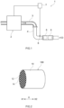
- FIG. 1 schematically illustrates an exhaust system in which the particulate filter according to the present embodiment is disposed.
- an exhaust gas purification device 1 is provided in an exhaust passage of an internal combustion engine 2.
- An air-fuel mixture containing oxygen and fuel gas is supplied to the internal combustion engine 2.
- the internal combustion engine 2 converts thermal energy in combustion of the air-fuel mixture to kinetic energy.
- Exhaust gas generated by combustion of the air-fuel mixture is discharged to the exhaust passage configured by an exhaust manifold 3 and an exhaust pipe 4 as illustrated with an arrow in FIG. 1 .
- the side in the flow direction of exhaust gas closer to the internal combustion engine 2 is described herein as the upstream side, and the side far from the internal combustion engine 2 is described herein as the downstream side for convenience of description.
- the exhaust gas purification device 1 purifies the exhaust gas discharged to the exhaust passage.
- the exhaust gas purification device 1 includes an engine control unit (ECU) 7 and a sensor 8.
- the sensor 8 detects information regarding components of the exhaust gas and the temperature of the exhaust gas.
- the ECU 7 receives the result of detection by the sensor 8 as one of multiple pieces of information for controlling an operation of the internal combustion engine 2.
- the exhaust gas purification device 1 illustrated in FIG. 1 further includes a catalyst section 5 and a filter section 6.
- the catalyst section 5 is provided in the exhaust pipe 4.
- An exhaust gas purifying catalyst that purifies ternary components of exhaust gas, i.e., NO x , HC, and CO, can be used in the catalyst section 5.
- the specific structure of the exhaust gas purifying catalyst used in the catalyst section 5 does not characterize the present invention, and a detailed description thereof is thus omitted.
- the catalyst section 5 is disposed on the upstream side of the filter section 6 in the exhaust gas purification device 1 illustrated in FIG. 1 , the location of the catalyst section is not specifically limited.
- the catalyst section may be disposed on the downstream side of the filter section.
- each of catalyst sections in a pair may be provided on the upstream and downstream sides of the filter section.
- the filter section 6 collects particulate matter (PM) in the exhaust gas to purify the exhaust gas.
- the particulate filter according to the present embodiment can be used in the filter section 6 of the exhaust gas purification device 1.
- the particulate filter according to the present embodiment is disposed in the exhaust passage (the exhaust pipe 4) of the internal combustion engine 2 as one constituent element of the exhaust gas purification device 1.
- FIG. 2 is a perspective view schematically illustrating the particulate filter according to the present embodiment.
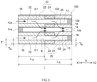
- FIG. 3 schematically illustrates a cross-section of the particulate filter illustrated in FIG. 2 , taken along an extending direction thereof (the flow direction X of exhaust gas).
- FIG. 4 schematically illustrates a cross-section of the particulate filter, taken along a radial direction thereof (a direction perpendicular to the flow direction X of exhaust gas).
- FIG. 5 is a schematic enlarged cross-sectional view of a region V in FIG. 3 .
- a particulate filter 100 includes a wall-flow structure substrate 10 and a wash coat layer 20 formed inside a partition 16 of the substrate 10.
- a wash coat layer 20 formed inside a partition 16 of the substrate 10.
- the particulate filter 100 uses the cylindrical substrate 10 extending along in the flow direction X of exhaust gas.
- the substrate 10 has a wall-flow structure as described above.
- the substrate 10 has a honeycomb structure having a plurality of hollow portions (cells 12 and 14).
- the cells 12 and 14 extend along the flow direction X of exhaust gas.
- the cells 12 and 14 of the substrate 10 according to the present embodiment are formed by inlet cells 12 and outlet cells 14 adjacent to the inlet cells 12, as illustrated in FIGS. 3 and 4 .
- the inlet cells 12 and the outlet cells 14 are partitioned by the porous partition 16.
- Various materials that can be conventionally used for this type of purpose are usable for the substrate 10 without any limitation.
- the material for the substrate 10 examples include ceramic, such as cordierite or silicon carbide (SiC), and an alloy (e.g., stainless steel).
- the outer shape of the substrate is not specifically limited and may be, for example, an elliptical cylinder or a polygonal prism, although the cylindrical substrate 10 is used in the present embodiment.
- the inlet cells 12 are cells open only at an end on the exhaust gas inflow side X1 (see FIG. 3 ). That is, in each inlet cell 12, the end on the exhaust gas inflow side X1 is open to the outside of the filter as a gas inlet 12a, and an end on the exhaust gas outflow side X2 is sealed with a sealing section 12b.
- the outlet cells 14 are cells open only at the end on the exhaust gas outflow side X2. That is, in each outlet cell 14, the end on the exhaust gas inflow side X1 is sealed with a sealing section 14a, and the end on the exhaust gas outflow side X2 is open to the outside of the filter as a gas outlet 14b.
- the shapes and sizes of the inlet cells 12 and the outlet cells 14 can be changed as appropriate, in consideration of the flow rate of exhaust gas supplied to the particulate filer 100 and the components of the exhaust gas.
- the cross-sectional shape of the cells 12 and 14 in a cross-section perpendicular to the extending direction X of the substrate 10 is a square in the present embodiment as illustrated in FIG. 4 .
- the cross-sectional area of each inlet cell 12 and that of each outlet cell 14 may be almost the same as each other or different from each other in consideration of the flow rate of exhaust gas.
- the cross-sectional shape of the cells 12 and 14 is not limited to a square as in the present embodiment. Commonly used shapes, for example, a parallelogram, a rectangle, a trapezoid, a triangle, a pentagon, and a circle can be adopted without any particular limitation.
- the substrate 10 is formed such that the inlet cell 12 and the outlet cell 14 are adjacent to each other as illustrated in FIGS. 2 and 4 .
- the substrate 10 according to the present embodiment is formed such that the inlet cells 12 and the outlet cells 14 both having a square cross-sectional shape are disposed in a checkered pattern.
- the inlet cell 12 and the outlet cell 14 are partitioned by the corresponding partition 16, as described above.
- each of the partitions 16 formed in a lattice extends along the flow direction X of exhaust gas, and spaces surrounded by the partitions 16 form the cells 12 and 14 (see FIGS. 3 and 4 ).
- the partition 16 is porous and has a plurality of fine pores. Specifically, a wall body 17 of the partition 16 is provided with a plurality of fine pores 18 illustrated in FIG. 5 .
- the inlet cells and the outlet cells communicate with each other through a part of the fine pores 18.
- exhaust gas having flowed into the inlet cells 12 is allowed to pass through the partition 16 and flow out to the outlet cells 14, as illustrated with arrows in FIG. 3 .
- a thickness T and a total length L of the partition 16 are preferably adjusted from the viewpoint of achieving both PM collection performance and pressure-drop reduction performance.
- the thickness T of the partition 16 is preferably about 0.2 mm to about 1.6 mm.
- the total length L of the partition 16 is preferably about 50 mm to about 500 mm and is more preferably 100 mm to 200 mm.
- the porosity of the partition 16 is preferably 40% or more, more preferably 45% or more, further preferably 50% or more, and particularly preferably 55% or more from the viewpoint of reducing an increase in the pressure drop. Meanwhile, the upper limit of the porosity of the partition 16 is preferably 80% or less, more preferably 75% or less, further preferably 70% or less, and particularly preferably 65% or more from the viewpoint of maintaining the mechanical strength of the substrate 10.
- the "porosity of the partition” as used herein refers to a ratio of the volume of the fine pores 18 to the total volume of the partition 16 of the substrate 10 (i.e., the total volume of the wall body 17 and the fine pores 18) and is a value measured by a mercury intrusion technique.
- the average pore diameter of the fine pores 18 is preferably 1 ⁇ m or more, more preferably 5 ⁇ m or more, further preferably 7 ⁇ m or more, and particularly preferably 10 ⁇ m or more from the viewpoint of improving the pressure-drop reduction performance.
- the upper limit of the average pore diameter of the fine pores 18 is preferably 50 ⁇ m or less, more preferably 40 ⁇ m or less, further preferably 30 ⁇ m or less, and particularly preferably 25 ⁇ m or les from the viewpoint of improving the PM collection performance.
- the "average pore diameter of the fine pores 18" as used herein refers to a mean of pore distribution obtained by the mercury intrusion technique.
- the wash coat layer 20 is a coating layer formed inside the partition 16 of the substrate 10.
- the wash coat layer 20 is a porous heat-resistant layer formed on the walls of the fine pores 18 (a surface of the wall body 17 in contact with the fine pores 18) as illustrated in FIG. 5 .
- the wash coat layer 20 can have a function of improving high temperature stability and water absorbency, for example.
- the wash coat layer 20 can also contribute to improvement in the PM collection performance by an increase in the surface area and/or a size reduction of the fine pores 18.
- Conventionally known materials can be used for the wash coat layer 20 in the present embodiment without any limitation.
- the wash coat layer 20 is mainly made of a heat-resistant material.
- the wash coat layer 20 preferably contains 50 mass% or more of heat-resistant material and more preferably 85 mass% or more.
- a refractory specified in JIS R2001 can be used as the heat-resistant material.
- the refractory include neutral refractories, such as alumina (Al 2 O 3 ), acid refractories, such as silica (SiO 2 ) and zirconia (ZrO 2 ), and basic refractories, such as magnesia (MgO) and calcia (CaO).
- Alumina preferably, activated alumina is preferable among these refractories.
- the heat-resistant material for the wash coat layer 20 may be formed of only one of the above-described refractories or a mixture (or a complex) of two or more of the above-described refractories.
- the complex are ceria-zirconia composite oxides.
- the wash coat layer 20 may contain another material (typically inorganic oxide) as a secondary component.
- the secondary component include rare earth metal oxides, such as yttria (Y 2 O 3 ), and alkaline earth metal oxides, such as barium oxide (BaO).
- the wash coat layer 20 is substantially not present on a surface 16a of the partition 16 in contact with the cells 12 and 14 (see FIG. 5 ) from the viewpoint of surely reducing a rapid increase in the pressure drop caused by blockage of the cells 12 and 14 with the wash coat layer 20.
- the wording "the wash coat layer is substantially not present on the surface of the partition" means that, assuming that the total coating amount of the wash coat layer 20 is 100%, the amount of coating of the wash coat layer 20 inside the fine pores 18 of the partition 16 is 90% or more, and more preferably 95% or more.
- the wash coat layer 20 in the present embodiment includes an inlet layer 22 and an outlet layer 24.
- the thicknesses and lengths of the inlet layer 22 and the outlet layer 24 are set such that the inlet layer 22 and the outlet layer 24 partially overlap each other.
- Each layer will be described below.
- the inlet layer 22 is a wash coat layer formed in a region near the gas inlet 12a including the partition 16. Specifically, the inlet layer 22 is formed to have a predetermined thickness from a surface of the partition 16 in contact with the inlet cells 12 toward the inner side of the partition 16 and to have a predetermined length along the extending direction of the partition 16 (the flow direction X of exhaust gas) from near the end on the exhaust gas inflow side X1.
- a thickness T A of the inlet layer 22 is not specifically limited and may be 50% or more of the thickness T of the partition 16.
- the thickness T A of the inlet layer 22 is preferably set to 60% or more, more preferably 70% or more, and further preferably 80% or more of the thickness T from the viewpoint of ensuring the sufficient volume of the inlet layer 22 and achieving suitable PM collection performance.
- the upper limit of the thickness Ta of the inlet layer 22 is not specifically limited and may be 100% or less, 95% or less, or 90% or less of the thickness T of the partition 16.
- a region where the inlet layer 22 is formed, as used herein, is referred to as the "inlet region", as described above.
- the "inlet region” includes a region where the outlet layer 24 to be described later and the inlet layer 22 overlap each other.
- the inlet layer 22 contains a precious metal catalyst.
- the precious metal catalyst is a catalyst material having a function of promoting combustion of PM and contains a precious metal, such as gold (Au), silver (Ag), palladium (Pd), rhodium (Rh), platinum (Pt), ruthenium (Ru), iridium (Ir), or osmium (Os).
- a precious metal such as gold (Au), silver (Ag), palladium (Pd), rhodium (Rh), platinum (Pt), ruthenium (Ru), iridium (Ir), or osmium (Os).
- platinum group elements such as Pt, Pd, and Rh, are particularly excellent in the action of promoting combustion of PM and are therefore particularly suitable as the precious metal contained in the inlet layer 22.
- the precious metal catalyst may contain a support that supports the precious metal in addition to the aforementioned precious metal.
- Examples of the material for the support include alumina (Al 2 O 3 ), rare earth metal oxides, alkaline metal oxides, alkaline earth metal oxides, zirconia (ZrO 2 ), ceria (CeO 2 ), silica (SiO 2 ), magnesia (MgO), and titania (TiO 2 ).
- alumina Al 2 O 3
- rare earth metal oxides alkaline metal oxides, alkaline earth metal oxides, zirconia (ZrO 2 ), ceria (CeO 2 ), silica (SiO 2 ), magnesia (MgO), and titania (TiO 2 ).
- the content of the precious metal catalyst in the inlet layer 22 (a ratio of the content (g) of the precious metal catalyst to a volume of 1 L of the inlet layer 22) is 0.1 g/L or more.
- the content of the precious metal catalyst in the inlet layer 22 is more preferably 0.5 g/L or more, further preferably 0.7 g/L or more, and particularly preferably 1 g/L or more from the viewpoint of maintaining the gas flowability in the inlet region at an even higher level.
- the upper limit of the content of the precious metal catalyst in the inlet layer 22 is not specifically limited and may be 20 g/L or less. From the viewpoint of easily forming the inlet layer 22, this upper limit is preferably 10 g/L or less, more preferably 7 g/L or less, further preferably 5 g/L or less, and particularly preferably 2 g/L or less.
- the length of the inlet layer 22 (i.e., a length L A of the inlet region) in the extending direction of the partition 16 is set to 50% or more of the total length L of the partition 16 (assumed as being 100%).
- the length L A of the inlet region is preferably 55% or more and more preferably 60% or more of the total length L of the partition from the viewpoint of achieving more suitable PM collection performance.
- the upper limit of the length L A of the inlet region is set to 75% or less of the total length L in the present embodiment.
- the upper limit of the length L A of the inlet region is preferably 70% or less of the total length L of the partition from the viewpoint of suitably ensuring the PM collection performance during the high load operation.
- the outlet layer 24 is a wash coat layer formed in a region near the gas outlet 14b including the partition 16. Specifically, the outlet layer 24 is formed to have a predetermined thickness T B from a surface of the partition 16 in contact with the outlet cell 14 toward the inner side of the partition 16 and to have a predetermined length along the extending direction of the partition 16 (the flow direction X of exhaust gas) from near the end on the exhaust gas outflow side X2.
- the thickness of the outlet layer 24 is preferably 50% or more, more preferably 60% or more, and further preferably 70% or more of the thickness T of the partition 16 from the viewpoint of improving the PM collection performance.
- the upper limit of the thickness T B of the outlet layer 24 is not specifically limited and may be 100% or less, 95% or less, 90% or less, or 85% or less of the thickness T of the partition 16.
- a region where only the outlet layer 24 is formed, as used herein, is referred to as the "outlet region", as described above.
- the outlet layer 24 contains substantially no precious metal catalyst (e.g., Au, Ag, Pd, Rh, Pt, Ru, Ir, and Os), unlike the inlet layer 22 described above.
- substantially no precious metal catalyst e.g., Au, Ag, Pd, Rh, Pt, Ru, Ir, and Os
- the wording "contain(s) substantially no precious metal catalyst” means that a component interpreted as a precious metal catalyst is not added intentionally. Therefore, a case where a small amount of component that can be interpreted as a precious metal catalyst and originates from a material, a manufacturing process, or the like is contained and a case where a small amount of a precious metal catalyst has migrated from another catalyst layer to the outlet layer (e.g., a case where the precious metal catalyst has migrated from the inlet layer to the outlet layer), for example, are included in the concept "contain(s) substantially no precious metal catalyst” as used herein.
- a ratio (g/L) of the content of the precious metal catalyst to the volume of the outlet layer 24 is 0.05 g/L or less (preferably 0.03 g/L or less, more preferably 0.01 g/L or less, further preferably 0.005 g/L or less, and particularly preferably 0.001 g/L or less), it can be said that the outlet layer 24 "contains substantially no precious metal catalyst".
- the above-described particulate filter 100 according to the present embodiment can achieve both PM collection performance and pressure-drop reduction performance at high levels.
- exhaust gas G1 at the early stage of operation is likely to pass through the inlet region of the partition 16 due to its low flow rate, as illustrated in FIG. 3 .
- the exhaust gas G1 at the early stage of operation contains a lot of PM and has a low temperature. Therefore, PM is hard to burn, and the PM collection performance can be easily improved by deposition of PM. It is thus possible to suitably collet PM even in the inlet region where the precious metal catalyst is present.
- exhaust gas with a low PM content is supplied at a high flow rate.
- a large increase in the pressure drop can be prevented because the temperature of the particulate filter 100 has risen sufficiently and the recovery of gas flowability by combustion of PM suitably occurs in the upstream-side region.
- Exhaust gas G2 during a high load operation is likely to pass through the outlet region of the partition 16 due to its high flow rate. Since the exhaust gas G2 during the high load operation contains a lot of PM, the outlet region is required to have high PM collection performance. Meanwhile, the particulate filter 100 according to the present embodiment contains substantially no precious metal catalyst in the outlet region, and it is thus possible to improve PM collection performance in the outlet region beforehand before the high load operation is performed. Since the exhaust gas G2 during the high load operation has a relatively high temperature, deposited PM can be burned little by little even if there is no precious metal catalyst. Accordingly, a rapid increase in the pressure drop is less likely to occur even if exhaust gas with a high flow rate during the high load operation is supplied to the outlet region.
- Another material can be added to the wash coat layer of the particulate filter disclosed herein, as long as that material does not spoil the essence of the present invention.
- Examples of the material that can be added to the wash coat layer include an OSC material (a material with oxygen storage capacity), a NO x adsorber, and a selective catalytic reduction (SCR) catalyst.
- the OSC material is a material that stores therein oxygen when an oxygen concentration in exhaust gas is high (that is, an air-fuel ratio is lean), and discharges oxygen when the oxygen concentration in exhaust gas is low (that is, the air-fuel ratio is rich).
- the OSC material include a material containing cerium oxide (ceria: CeO 2 ) as a base.
- Examples of the material containing CeO 2 as a base include CZ based composite materials (CeO 2 -ZrO 2 composite oxides).
- the CZ based composite material is a polycrystalline substance or a single crystal that mainly contains CeO 2 and ZrO 2 .
- Various additional component(s) may be added to the CZ based composite material. Examples of the additional component include rare earth oxides, alkaline metal oxides, alkaline earth metal oxides, transition metals, alumina, and silica.
- the OSC material has an action of maintaining exhaust gas passing through the partition 16 to be an oxidizing atmosphere and therefore can exhibit a function of promoting combustion of PM. It is thus preferable that the outlet layer 24 contains substantially no OSC material in the case where the OSC material is added to the wash coat layer 20. By this configuration, it is possible to achieve both pressure-drop reduction performance and PM collection performance at higher levels.
- the wording "the outlet layer contains substantially no OSC material" also includes a case where the outlet layer contains a small amount of component interpreted as the OSC material and originating from a raw material, a manufacturing process, or the like.
- the outlet layer 24 contains substantially no OSC material.
- the NO x adsorber is a material that adsorbs NO x in exhaust gas when an air-fuel ratio of the exhaust gas is lean, i.e., oxygen is excessive, and discharges NO x when the air-fuel ratio becomes rich.
- a basic material containing one or more of metals that can donate electrons to NO x can be preferably used for the NO x adsorber.
- the basic material include alkaline metals, such as potassium (K), sodium (Na), and cesium (Cs), alkaline earth metals, such as barium (Ba) and calcium (Ca), rare earth elements, such as lanthanoid, and other metals, such as silver (Ag), copper (Cu), iron (Fe), and iridium (Ir).
- barium compounds e.g., barium sulfate
- the SCR catalyst purifies nitrogen oxide (NO x ) in exhaust gas.
- the SCR catalyst is not specifically limited.
- the SCR catalyst include ⁇ zeolite and silicoaluminophosphate (SAPO) zeolite.
- SAPO include SAPO-5, SAPO-11, SAPO-14, SAPO-17, SAPO-18, SAPO-34, SAPO-39, SAPO-42, and SAPO-47.
- the SCR catalyst may contain any metal component.
- the metal component examples include copper (Cu), iron (Fe), sodium (Na), potassium (K), magnesium (Mg), calcium (Ca), cobalt (Co), nickel (Ni), zinc (Zn), silver (Ag), lead (Pb), vanadium (V), chromium (Cr), molybdenum (Mo), yttrium (Y), cerium (Ce), neodymium (Nd), tungsten (W), indium (In), and iridium (Ir). It is possible to purify NO x more efficiently by containing the above-described metal in the SAPO.
- a reducing agent supply means that supplies a reducing agent for generating ammonia (e.g., urea water), on the upstream side of the particulate filter (e.g., on the upstream side of the filter section 6 in FIG. 1 ).
- the particulate filter 100 can be disposed in the exhaust passage of the internal combustion engine 2 as the filter section 6 that removes PM in exhaust gas, as described above (see FIG. 1 ).
- the particulate filter disclosed herein is not limited thereto and can be used for various purposes.
- the particulate filter disclosed herein can serve as a three-way catalyst that purifies hydrocarbon (HC), carbon monoxide (CO), and nitrogen oxide (NO x ) because the filter contains a precious metal catalyst in the inlet layer thereof. Therefore, the particulate filter disclosed herein can also be used as an exhaust gas purifying catalyst that serves as both the catalyst section 5 and the filter section 6 in FIG. 1 .
- the OSC material and/or the NO x adsorber described above are/is added to the wash coat layer.
- the particulate filter disclosed herein is particularly preferably used in the case where the internal combustion engine 2 is a gasoline engine of an automobile, although this description is not intended to limit the present invention.
- Exhaust gas emitted from the gasoline engine has a relatively high temperature, and therefore PM is less likely to be deposited inside fine pores of a partition.
- the particulate filter disclosed herein contains substantially no precious metal catalyst in the outlet region, and it is thus possible to allow PM to be deposited in the outlet region in a suitable manner. Therefore, the particulate filter disclosed herein can suitably improve PM collection performance even when used in the gasoline engine.
- the particulate filter disclosed herein is not limited to being used in the gasoline engine and can also be used for purifying exhaust gas from another engine (e.g., a diesel engine).
- another engine e.g., a diesel engine
- the particulate filter can serve as both an SCR device that purifies NO x contained in the exhaust gas from the diesel engine and a filter section that removes PM.
- the particulate filter disclosed herein is not limited to a particulate filter manufactured by the following manufacturing method.
- the particulate filter 100 according to the present embodiment can be manufactured, for example, by preparing a slurry containing materials for the wash coat layer 20 and introducing the slurry into the fine pores 18 of the partition 16 of the substrate 10. Each process will be described below.
- a slurry is prepared by dispersing the above-described materials for the wash coat layer 20 in a predetermined dispersion medium.
- the dispersion medium may be a polar solvent (e.g., water) or a nonpolar solvent (e.g., methanol).
- the slurry may contain an organic component for viscosity adjustment in addition to the above-described material for the wash coat layer 20 and the dispersion medium.
- the organic component for viscosity adjustment include cellulose polymers, such as carboxymethyl cellulose (CMC), methyl cellulose (MC), hydroxypropyl methyl cellulose (HPMC), and hydroxyethyl methyl cellulose (HEMC).
- two kinds of slurries are prepared which include a slurry for the inlet layer containing a precious metal catalyst and a slurry for the outlet layer that contains substantially no precious metal catalyst.
- a detailed description regarding the precious metal catalyst is omitted because it overlaps the above description.
- the slurry for the inlet layer and the slurry for the outlet layer may be different from each other in a material other than the precious metal catalyst. For example, it is possible to make the viscosity of the slurry for the inlet layer and that of the slurry for the outlet layer different from each other by making the addition amount and/or the type of the organic component for viscosity adjustment different. It is thus possible to easily adjust a region where each of the inlet layer and the outlet layer is formed.
- the wash coat layer 20 is formed by introducing the above-described slurries into the fine pores 18 of the partition 16.
- a means that introduces the slurries into the fine pores 18 is not specifically limited.
- a conventionally known means can be used without any limitation.
- Examples of the slurry introducing means include air blowing and suction coating. In the case of using air blowing, an end of the substrate 10 is immersed in the slurry, causing the slurry to penetrate into the cells 12 and 14. Thereafter, the substrate 10 is taken out, and air blowing is performed. The slurry is thus introduced into the fine pores 18. In the case of using suction coating, while an end of the substrate 10 is immersed in the slurry, the slurry is sucked from the other end thereof. The slurry is thus introduced into the fine pores 18.
- the particulate filter 100 is provided with the wash coat layer 20 including the inlet layer 22 and the outlet layer 24.
- the slurry is sucked through the gas outlet 14b of the substrate 10 while the gas inlet 12a is immersed in the slurry for the inlet layer.
- the slurry for the inlet layer is applied from near the end on the exhaust gas inflow side X1 to have a predetermined length and a predetermined thickness.
- the thus applied slurry is dried and fired, so that the inlet layer 22 is formed.
- the slurry is sucked through the gas inlet 12a of the substrate 10 while the gas outlet 14b is immersed in the slurry for the outlet layer.
- the slurry for the outlet layer is applied from near the end on the exhaust gas outflow side X2 to have a predetermined length and a predetermined thickness.
- the thus applied slurry is dried and fired, so that the outlet layer 24 is formed.
- it is possible to control the region where each slurry is to be applied by adjusting the viscosity of the slurry and/or the suction power of the suction coating device. Accordingly, a portion of the inlet layer 22 and a portion of the outlet layer 24 after firing can be made to overlap each other, and the length of the inlet layer 22 to the total length L of the partition 16 can be controlled to be 50% or more and 75% or less.
- the order of forming the inlet layer 22 and the outlet layer 24 is not specifically limited.
- the inlet layer 22 may be formed after the outlet layer 24 is formed.
- sucking the slurry for the inlet layer having the appropriately set viscosity with appropriate suction power it is easy to make distribution of the thickness Ta of the inlet layer 22 in the flow direction X of exhaust gas uniform, and it is possible to make fine pores in the inlet region small and reduce variation in the pore diameters (that is, make distribution of pore diameters sharp).
- the inlet layer 22 is formed by drying and firing the slurry for the inlet layer and thereafter the slurry for the outlet layer is introduced into the substrate.
- the slurry for the outlet layer may be introduced and both the slurries for the inlet layer and for the outlet layer may be fired at the same time. Also in this case, it is possible to form the wash coat layer 20 including the inlet layer 22 and the outlet layer 24.
- Air blowing may be carried out after introduction of the slurry and before drying of the slurry. This makes it possible to prevent the slurry from remaining in the cells 12 and 14, which can suppress the formation of the wash coat layer on the surface 16a of the partition 16 (see FIG. 5 ) in contact with the cells 12 and 14.
- the inlet layer 22 contains a precious metal catalyst
- the outlet layer 24 contains substantially no precious metal catalyst.
- the length L A of the inlet layer 22 with respect to the total length L of the partition 16 is limited to 50% or more and 75% or less. As described above, the particulate filter 100 having this configuration can achieve both PM collection performance and pressure-drop reduction performance at high levels as a whole.
- test examples concerning the present invention are described below. The following description, however, is not intended to limit the present invention to the test examples.
- a plurality of particulate filters different from each other in a region containing a precious metal catalyst inside a partition were fabricated.
- evaluation was performed with regard to PM collection performance and pressure-drop reduction performance.
- Alumina powder, barium oxide powder, and ion-exchange water were mixed to prepare a Pd-free slurry. While immersing a gas inlet of a wall-flow filter substrate (made of cordierite and having a length of 152.4 mm and the total capacity of cells of 1.7 L) in the Pd-free slurry, this slurry was sucked through a gas outlet by using a suction coating device, thus introducing the Pd-free slurry to an upstream region of a partition in the substrate such that it has a predetermined length and a predetermined thickness. Then, the slurry was dried and fired to form an inlet layer.
- a wall-flow filter substrate made of cordierite and having a length of 152.4 mm and the total capacity of cells of 1.7 L
- the slurry was also sucked through the gas inlet while immersing the gas outlet in the Pd-free slurry, thus introducing the Pd-free slurry to a downstream region of the partition such that it has a predetermined length and a predetermined thickness. Then, the slurry was also dried and fired to form an outlet layer.
- the “lengths L A and L B ", the "coating amount (amount of introduced slurry)", and the "Pd content” are shown in Table 1 for each of an inlet region and an exist-side region.
- a Pd-containing slurry was prepared which had the same components as the Pd-free slurry of Sample 1 except that the Pd-containing slurry contained a palladium nitrate solution (a precursor of a precious metal catalyst). That is, the palladium nitrate solution, alumina powder, barium oxide powder, and ion-exchange water were mixed to prepare the Pd-containing slurry. The Pd-containing slurry was then introduced to both the upstream region and the downstream region of the partition, followed by drying and firing of the slurry introduced in each region. As a result, a particulate filter containing a precious metal catalyst (Pd) in both the inlet layer and the outlet layer was fabricated. Other conditions were set to be the same as those in Sample 1.
- Pd precious metal catalyst
- the above-described Pd-containing slurry was introduced to the upstream region of the partition to form the inlet layer containing the precious metal catalyst (Pd), and the Pd-free slurry was introduced to the downstream region of the partition to form the outlet layer containing no precious metal catalyst.
- suction power of the suction coating device was adjusted to make the length of the inlet layer (the length L A of the inlet region) with respect to the total length L of the partition equal to 40%.
- Other conditions were set to be the same as those in Sample 1.
- suction power of the suction coating device was made stronger than in Sample 3 to make the length of the inlet layer (the length L A of the inlet region) with respect to the total length L of the partition longer than that in Sample 3.
- the length L A of the inlet region in Sample 4 was set to 50% of the total length L of the partition.
- the length L A of the inlet region in Sample 5 was set to 60% of the total length L of the partition.
- the length L A of the inlet region in Sample 6 was set to 75% of the total length L of the partition.
- the length L A of the inlet region in Sample 7 was set to 80% of the total length L of the partition.
- Other conditions were the same as those in Sample 3.
- PM collection efficiency % Y ⁇ X / Y ⁇ 100 [Table 1] Inlet region Outlet region PM collection efficiency Length L A (%) Coating amount (g/L) Pd content (g/L) Length L B (%) Coating amount (g/L) Pd content (g/L) Sample 1 60 50 - 40 50 - 93.9 Sample 2 60 50 0.15 40 50 0.15 81.8 Sample 3 40 50 0.15 60 50 - 77.9 Sample 4 50 50 0.15 50 50 - 82.8 Sample 5 60 50 0.15 40 50 - 85.1 Sample 6 75 50 0.15 25 50 - 89.7 Sample 7 80 50 0.15 20 50 - 78.3
- Samples 4 to 6 in which the length L A of the inlet region with respect to the total length L of the partition was set to 50% or more and 75% or less can exhibit a higher level of PM collection performance than Sample 2 in which the precious metal catalyst was contained in both the inlet layer and the outlet layer.
- Regeneration treatment was performed on the particulate filters of Samples 1, 2, and 5, and changes in the pressure drop and the weight of deposited PM in the regeneration treatment were measured.
- the particulate filter in which PM had been deposited during the above-described measurement of PM collection efficiency was attached to an engine bench and was subjected to the regeneration treatment.
- high-temperature exhaust gas having a temperature of 500°C and an air-fuel ratio of 14.7 was supplied for 60 minutes.
- a pressure drop (kPa) and the weight of deposited PM (g) were measured immediately after (0 minutes after), 30 minutes after, and 60 minutes after the start of the regeneration treatment. Results are shown in Table 2.
Landscapes
- Chemical & Material Sciences (AREA)
- Engineering & Computer Science (AREA)
- Chemical Kinetics & Catalysis (AREA)
- Materials Engineering (AREA)
- Organic Chemistry (AREA)
- Combustion & Propulsion (AREA)
- Mechanical Engineering (AREA)
- General Engineering & Computer Science (AREA)
- Geometry (AREA)
- Physics & Mathematics (AREA)
- Health & Medical Sciences (AREA)
- General Chemical & Material Sciences (AREA)
- Biomedical Technology (AREA)
- Oil, Petroleum & Natural Gas (AREA)
- Analytical Chemistry (AREA)
- Environmental & Geological Engineering (AREA)
- Toxicology (AREA)
- Catalysts (AREA)
- Exhaust Gas Treatment By Means Of Catalyst (AREA)
- Exhaust Gas After Treatment (AREA)
- Processes For Solid Components From Exhaust (AREA)
- Filtering Of Dispersed Particles In Gases (AREA)
Applications Claiming Priority (2)
| Application Number | Priority Date | Filing Date | Title |
|---|---|---|---|
| JP2019119019A JP7414413B2 (ja) | 2019-06-26 | 2019-06-26 | パティキュレートフィルタ |
| PCT/JP2020/025265 WO2020262623A1 (ja) | 2019-06-26 | 2020-06-26 | パティキュレートフィルタ |
Publications (3)
| Publication Number | Publication Date |
|---|---|
| EP3971397A1 EP3971397A1 (en) | 2022-03-23 |
| EP3971397A4 EP3971397A4 (en) | 2022-07-27 |
| EP3971397B1 true EP3971397B1 (en) | 2024-08-28 |
Family
ID=74060152
Family Applications (1)
| Application Number | Title | Priority Date | Filing Date |
|---|---|---|---|
| EP20833399.7A Active EP3971397B1 (en) | 2019-06-26 | 2020-06-26 | Particulate filter |
Country Status (5)
| Country | Link |
|---|---|
| US (1) | US11808188B2 (enExample) |
| EP (1) | EP3971397B1 (enExample) |
| JP (1) | JP7414413B2 (enExample) |
| CN (1) | CN114080493B (enExample) |
| WO (1) | WO2020262623A1 (enExample) |
Families Citing this family (3)
| Publication number | Priority date | Publication date | Assignee | Title |
|---|---|---|---|---|
| CN117999124A (zh) * | 2021-09-22 | 2024-05-07 | 三井金属矿业株式会社 | 废气净化用催化剂 |
| WO2023167128A1 (ja) * | 2022-03-01 | 2023-09-07 | 株式会社キャタラー | 排ガス浄化用触媒の製造方法 |
| CN119435178B (zh) * | 2024-10-28 | 2025-10-10 | 中国第一汽车股份有限公司 | 发动机排气后处理装置以及车辆 |
Family Cites Families (28)
| Publication number | Priority date | Publication date | Assignee | Title |
|---|---|---|---|---|
| JP4393039B2 (ja) | 2001-07-18 | 2010-01-06 | イビデン株式会社 | 触媒つきフィルタ、その製造方法及び排気ガス浄化システム |
| DE10226108A1 (de) * | 2002-06-12 | 2004-01-08 | J. Eberspächer GmbH & Co. KG | Abgasanlage mit Partikelfilter für Dieselmotoren |
| JP2005009454A (ja) | 2003-06-20 | 2005-01-13 | Tokyo Yogyo Co Ltd | 排ガス浄化用フィルタ |
| WO2009100097A2 (en) | 2008-02-05 | 2009-08-13 | Basf Catalysts Llc | Gasoline engine emissions treatment systems having particulate traps |
| WO2008105081A1 (ja) * | 2007-02-28 | 2008-09-04 | Ibiden Co., Ltd. | ハニカムフィルタ |
| DE202007003597U1 (de) * | 2007-03-08 | 2008-07-17 | Mann+Hummel Gmbh | Vorrichtung zur Abgasnachbehandlung |
| JPWO2008126321A1 (ja) * | 2007-03-30 | 2010-07-22 | イビデン株式会社 | 排ガス浄化システム |
| US7871452B2 (en) * | 2007-10-01 | 2011-01-18 | Mazda Motor Corporation | Particulate filter |
| JP5419371B2 (ja) | 2008-03-17 | 2014-02-19 | 日本碍子株式会社 | 触媒担持フィルタ |
| US8758695B2 (en) * | 2009-08-05 | 2014-06-24 | Basf Se | Treatment system for gasoline engine exhaust gas |
| US20110047992A1 (en) | 2009-08-25 | 2011-03-03 | International Engine Intellectual Property Company, Llc | Partial coating of platinum group metals on filter for increased soot mass limit and reduced costs |
| JP2012036821A (ja) * | 2010-08-06 | 2012-02-23 | Mitsui Mining & Smelting Co Ltd | 内燃機関の排気ガス浄化装置 |
| JP6532826B2 (ja) * | 2013-12-11 | 2019-06-19 | 株式会社キャタラー | 排ガス浄化材 |
| WO2016060048A1 (ja) * | 2014-10-16 | 2016-04-21 | 株式会社キャタラー | 排ガス浄化用触媒 |
| JP6562673B2 (ja) | 2015-03-25 | 2019-08-21 | 日本碍子株式会社 | 排ガス浄化フィルタ、排ガス浄化装置、及び排ガス浄化装置の使用方法 |
| RU2704422C2 (ru) | 2015-03-30 | 2019-10-28 | Басф Корпорейшн | Многофункциональные фильтры для регулирования выбросов дизельного двигателя |
| WO2017163984A1 (ja) * | 2016-03-24 | 2017-09-28 | 株式会社キャタラー | 排ガス浄化装置 |
| JP6738185B2 (ja) * | 2016-04-07 | 2020-08-12 | 株式会社キャタラー | 排ガス浄化装置 |
| JP7305536B2 (ja) * | 2016-08-05 | 2023-07-10 | ビーエーエスエフ コーポレーション | ガソリンエンジン排出処理システムのための、単金属ロジウム含有四元変換触媒 |
| JP6346642B2 (ja) * | 2016-09-26 | 2018-06-20 | 株式会社キャタラー | 排ガス浄化用触媒 |
| JP2018103132A (ja) * | 2016-12-27 | 2018-07-05 | 株式会社キャタラー | 排ガス浄化用触媒 |
| CN111132761A (zh) | 2017-09-21 | 2020-05-08 | 株式会社科特拉 | 排气净化用催化剂体 |
| JP6487982B1 (ja) | 2017-09-28 | 2019-03-20 | 株式会社キャタラー | 排ガス浄化用触媒 |
| EP3673997B1 (en) * | 2017-10-19 | 2022-03-09 | Cataler Corporation | Exhaust gas purifying catalyst and its use |
| DE202017007047U1 (de) * | 2017-12-19 | 2019-04-29 | Umicore Ag & Co. Kg | Katalytisch aktives Partikelfilter |
| JP2019119019A (ja) | 2018-01-09 | 2019-07-22 | 日鍛バルブ株式会社 | 軸の製造方法 |
| CN111801163B (zh) * | 2018-03-30 | 2023-01-06 | 三井金属矿业株式会社 | 废气净化催化剂 |
| JP7037985B2 (ja) * | 2018-03-30 | 2022-03-17 | 日本碍子株式会社 | ハニカムフィルタ |
-
2019
- 2019-06-26 JP JP2019119019A patent/JP7414413B2/ja active Active
-
2020
- 2020-06-26 US US17/618,082 patent/US11808188B2/en active Active
- 2020-06-26 CN CN202080046665.XA patent/CN114080493B/zh active Active
- 2020-06-26 EP EP20833399.7A patent/EP3971397B1/en active Active
- 2020-06-26 WO PCT/JP2020/025265 patent/WO2020262623A1/ja not_active Ceased
Also Published As
| Publication number | Publication date |
|---|---|
| EP3971397A4 (en) | 2022-07-27 |
| JP2021004579A (ja) | 2021-01-14 |
| US11808188B2 (en) | 2023-11-07 |
| US20220316372A1 (en) | 2022-10-06 |
| CN114080493A (zh) | 2022-02-22 |
| JP7414413B2 (ja) | 2024-01-16 |
| WO2020262623A1 (ja) | 2020-12-30 |
| EP3971397A1 (en) | 2022-03-23 |
| CN114080493B (zh) | 2024-07-12 |
Similar Documents
| Publication | Publication Date | Title |
|---|---|---|
| JP5726414B2 (ja) | 触媒担持フィルタ、及び排ガス浄化システム | |
| CN107073463B (zh) | 废气净化用催化剂 | |
| EP2103342B1 (en) | Catalyst-carrying filter | |
| CN112055615B (zh) | 废气净化用催化剂 | |
| EP3434368B1 (en) | Exhaust gas purification device | |
| EP2276555B1 (en) | Exhaust gas purifying catalyst and manufacturing method of the same | |
| EP3162428A1 (en) | Exhaust gas purification device | |
| EP3001000B1 (en) | Diesel particulate filter and exhaust gas purification device | |
| US10981113B2 (en) | Exhaust gas purification catalyst body | |
| EP3854477B1 (en) | Particulate filter | |
| EP3689457B1 (en) | Exhaust-gas purifying catalyst | |
| CN107073465A (zh) | 废气净化用催化剂 | |
| JP2007218219A (ja) | ディーゼルパティキュレートフィルタ | |
| EP3971397B1 (en) | Particulate filter | |
| US12239968B2 (en) | Particulate filter | |
| JPWO2019221212A1 (ja) | 排ガス浄化触媒及びその製造方法 | |
| JP2008151100A (ja) | 排ガス浄化装置 | |
| JP7178432B2 (ja) | 排気浄化フィルタ | |
| JP2025101761A (ja) | パティキュレートフィルタおよび内部コート用スラリー |
Legal Events
| Date | Code | Title | Description |
|---|---|---|---|
| STAA | Information on the status of an ep patent application or granted ep patent |
Free format text: STATUS: THE INTERNATIONAL PUBLICATION HAS BEEN MADE |
|
| PUAI | Public reference made under article 153(3) epc to a published international application that has entered the european phase |
Free format text: ORIGINAL CODE: 0009012 |
|
| STAA | Information on the status of an ep patent application or granted ep patent |
Free format text: STATUS: REQUEST FOR EXAMINATION WAS MADE |
|
| 17P | Request for examination filed |
Effective date: 20211216 |
|
| AK | Designated contracting states |
Kind code of ref document: A1 Designated state(s): AL AT BE BG CH CY CZ DE DK EE ES FI FR GB GR HR HU IE IS IT LI LT LU LV MC MK MT NL NO PL PT RO RS SE SI SK SM TR |
|
| A4 | Supplementary search report drawn up and despatched |
Effective date: 20220628 |
|
| RIC1 | Information provided on ipc code assigned before grant |
Ipc: B01J 23/44 20060101ALI20220622BHEP Ipc: B01J 23/42 20060101ALI20220622BHEP Ipc: B01J 23/40 20060101ALI20220622BHEP Ipc: F01N 3/28 20060101ALI20220622BHEP Ipc: B01J 35/04 20060101ALI20220622BHEP Ipc: B01J 23/58 20060101ALI20220622BHEP Ipc: B01D 53/94 20060101ALI20220622BHEP Ipc: B01D 46/00 20220101ALI20220622BHEP Ipc: F01N 3/035 20060101AFI20220622BHEP |
|
| DAV | Request for validation of the european patent (deleted) | ||
| DAX | Request for extension of the european patent (deleted) | ||
| GRAP | Despatch of communication of intention to grant a patent |
Free format text: ORIGINAL CODE: EPIDOSNIGR1 |
|
| STAA | Information on the status of an ep patent application or granted ep patent |
Free format text: STATUS: GRANT OF PATENT IS INTENDED |
|
| RIC1 | Information provided on ipc code assigned before grant |
Ipc: B01J 37/02 20060101ALI20240418BHEP Ipc: B01J 35/56 20240101ALI20240418BHEP Ipc: B01D 46/24 20060101ALI20240418BHEP Ipc: F01N 3/021 20060101ALI20240418BHEP Ipc: B01J 37/00 20060101ALI20240418BHEP Ipc: B01J 23/46 20060101ALI20240418BHEP Ipc: B01J 21/04 20060101ALI20240418BHEP Ipc: B01J 23/44 20060101ALI20240418BHEP Ipc: B01J 23/42 20060101ALI20240418BHEP Ipc: B01J 23/40 20060101ALI20240418BHEP Ipc: F01N 3/28 20060101ALI20240418BHEP Ipc: B01J 23/58 20060101ALI20240418BHEP Ipc: B01D 53/94 20060101ALI20240418BHEP Ipc: B01D 46/00 20060101ALI20240418BHEP Ipc: F01N 3/035 20060101AFI20240418BHEP |
|
| INTG | Intention to grant announced |
Effective date: 20240507 |
|
| GRAS | Grant fee paid |
Free format text: ORIGINAL CODE: EPIDOSNIGR3 |
|
| GRAA | (expected) grant |
Free format text: ORIGINAL CODE: 0009210 |
|
| STAA | Information on the status of an ep patent application or granted ep patent |
Free format text: STATUS: THE PATENT HAS BEEN GRANTED |
|
| AK | Designated contracting states |
Kind code of ref document: B1 Designated state(s): AL AT BE BG CH CY CZ DE DK EE ES FI FR GB GR HR HU IE IS IT LI LT LU LV MC MK MT NL NO PL PT RO RS SE SI SK SM TR |
|
| REG | Reference to a national code |
Ref country code: CH Ref legal event code: EP |
|
| REG | Reference to a national code |
Ref country code: DE Ref legal event code: R096 Ref document number: 602020036814 Country of ref document: DE |
|
| REG | Reference to a national code |
Ref country code: IE Ref legal event code: FG4D |
|
| REG | Reference to a national code |
Ref country code: LT Ref legal event code: MG9D |
|
| PG25 | Lapsed in a contracting state [announced via postgrant information from national office to epo] |
Ref country code: NO Free format text: LAPSE BECAUSE OF FAILURE TO SUBMIT A TRANSLATION OF THE DESCRIPTION OR TO PAY THE FEE WITHIN THE PRESCRIBED TIME-LIMIT Effective date: 20241128 |
|
| REG | Reference to a national code |
Ref country code: AT Ref legal event code: MK05 Ref document number: 1718151 Country of ref document: AT Kind code of ref document: T Effective date: 20240828 |
|
| PG25 | Lapsed in a contracting state [announced via postgrant information from national office to epo] |
Ref country code: FI Free format text: LAPSE BECAUSE OF FAILURE TO SUBMIT A TRANSLATION OF THE DESCRIPTION OR TO PAY THE FEE WITHIN THE PRESCRIBED TIME-LIMIT Effective date: 20240828 Ref country code: NL Free format text: LAPSE BECAUSE OF FAILURE TO SUBMIT A TRANSLATION OF THE DESCRIPTION OR TO PAY THE FEE WITHIN THE PRESCRIBED TIME-LIMIT Effective date: 20240828 Ref country code: PL Free format text: LAPSE BECAUSE OF FAILURE TO SUBMIT A TRANSLATION OF THE DESCRIPTION OR TO PAY THE FEE WITHIN THE PRESCRIBED TIME-LIMIT Effective date: 20240828 Ref country code: GR Free format text: LAPSE BECAUSE OF FAILURE TO SUBMIT A TRANSLATION OF THE DESCRIPTION OR TO PAY THE FEE WITHIN THE PRESCRIBED TIME-LIMIT Effective date: 20241129 Ref country code: PT Free format text: LAPSE BECAUSE OF FAILURE TO SUBMIT A TRANSLATION OF THE DESCRIPTION OR TO PAY THE FEE WITHIN THE PRESCRIBED TIME-LIMIT Effective date: 20241230 |
|
| PG25 | Lapsed in a contracting state [announced via postgrant information from national office to epo] |
Ref country code: BG Free format text: LAPSE BECAUSE OF FAILURE TO SUBMIT A TRANSLATION OF THE DESCRIPTION OR TO PAY THE FEE WITHIN THE PRESCRIBED TIME-LIMIT Effective date: 20240828 |
|
| PG25 | Lapsed in a contracting state [announced via postgrant information from national office to epo] |
Ref country code: LV Free format text: LAPSE BECAUSE OF FAILURE TO SUBMIT A TRANSLATION OF THE DESCRIPTION OR TO PAY THE FEE WITHIN THE PRESCRIBED TIME-LIMIT Effective date: 20240828 |
|
| REG | Reference to a national code |
Ref country code: NL Ref legal event code: MP Effective date: 20240828 |
|
| PG25 | Lapsed in a contracting state [announced via postgrant information from national office to epo] |
Ref country code: IS Free format text: LAPSE BECAUSE OF FAILURE TO SUBMIT A TRANSLATION OF THE DESCRIPTION OR TO PAY THE FEE WITHIN THE PRESCRIBED TIME-LIMIT Effective date: 20241228 Ref country code: AT Free format text: LAPSE BECAUSE OF FAILURE TO SUBMIT A TRANSLATION OF THE DESCRIPTION OR TO PAY THE FEE WITHIN THE PRESCRIBED TIME-LIMIT Effective date: 20240828 |
|
| PG25 | Lapsed in a contracting state [announced via postgrant information from national office to epo] |
Ref country code: HR Free format text: LAPSE BECAUSE OF FAILURE TO SUBMIT A TRANSLATION OF THE DESCRIPTION OR TO PAY THE FEE WITHIN THE PRESCRIBED TIME-LIMIT Effective date: 20240828 |
|
| PG25 | Lapsed in a contracting state [announced via postgrant information from national office to epo] |
Ref country code: RS Free format text: LAPSE BECAUSE OF FAILURE TO SUBMIT A TRANSLATION OF THE DESCRIPTION OR TO PAY THE FEE WITHIN THE PRESCRIBED TIME-LIMIT Effective date: 20241128 Ref country code: ES Free format text: LAPSE BECAUSE OF FAILURE TO SUBMIT A TRANSLATION OF THE DESCRIPTION OR TO PAY THE FEE WITHIN THE PRESCRIBED TIME-LIMIT Effective date: 20240828 |
|
| PG25 | Lapsed in a contracting state [announced via postgrant information from national office to epo] |
Ref country code: RS Free format text: LAPSE BECAUSE OF FAILURE TO SUBMIT A TRANSLATION OF THE DESCRIPTION OR TO PAY THE FEE WITHIN THE PRESCRIBED TIME-LIMIT Effective date: 20241128 Ref country code: PT Free format text: LAPSE BECAUSE OF FAILURE TO SUBMIT A TRANSLATION OF THE DESCRIPTION OR TO PAY THE FEE WITHIN THE PRESCRIBED TIME-LIMIT Effective date: 20241230 Ref country code: PL Free format text: LAPSE BECAUSE OF FAILURE TO SUBMIT A TRANSLATION OF THE DESCRIPTION OR TO PAY THE FEE WITHIN THE PRESCRIBED TIME-LIMIT Effective date: 20240828 Ref country code: NO Free format text: LAPSE BECAUSE OF FAILURE TO SUBMIT A TRANSLATION OF THE DESCRIPTION OR TO PAY THE FEE WITHIN THE PRESCRIBED TIME-LIMIT Effective date: 20241128 Ref country code: NL Free format text: LAPSE BECAUSE OF FAILURE TO SUBMIT A TRANSLATION OF THE DESCRIPTION OR TO PAY THE FEE WITHIN THE PRESCRIBED TIME-LIMIT Effective date: 20240828 Ref country code: LV Free format text: LAPSE BECAUSE OF FAILURE TO SUBMIT A TRANSLATION OF THE DESCRIPTION OR TO PAY THE FEE WITHIN THE PRESCRIBED TIME-LIMIT Effective date: 20240828 Ref country code: IS Free format text: LAPSE BECAUSE OF FAILURE TO SUBMIT A TRANSLATION OF THE DESCRIPTION OR TO PAY THE FEE WITHIN THE PRESCRIBED TIME-LIMIT Effective date: 20241228 Ref country code: HR Free format text: LAPSE BECAUSE OF FAILURE TO SUBMIT A TRANSLATION OF THE DESCRIPTION OR TO PAY THE FEE WITHIN THE PRESCRIBED TIME-LIMIT Effective date: 20240828 Ref country code: GR Free format text: LAPSE BECAUSE OF FAILURE TO SUBMIT A TRANSLATION OF THE DESCRIPTION OR TO PAY THE FEE WITHIN THE PRESCRIBED TIME-LIMIT Effective date: 20241129 Ref country code: FI Free format text: LAPSE BECAUSE OF FAILURE TO SUBMIT A TRANSLATION OF THE DESCRIPTION OR TO PAY THE FEE WITHIN THE PRESCRIBED TIME-LIMIT Effective date: 20240828 Ref country code: ES Free format text: LAPSE BECAUSE OF FAILURE TO SUBMIT A TRANSLATION OF THE DESCRIPTION OR TO PAY THE FEE WITHIN THE PRESCRIBED TIME-LIMIT Effective date: 20240828 Ref country code: BG Free format text: LAPSE BECAUSE OF FAILURE TO SUBMIT A TRANSLATION OF THE DESCRIPTION OR TO PAY THE FEE WITHIN THE PRESCRIBED TIME-LIMIT Effective date: 20240828 Ref country code: AT Free format text: LAPSE BECAUSE OF FAILURE TO SUBMIT A TRANSLATION OF THE DESCRIPTION OR TO PAY THE FEE WITHIN THE PRESCRIBED TIME-LIMIT Effective date: 20240828 |
|
| PG25 | Lapsed in a contracting state [announced via postgrant information from national office to epo] |
Ref country code: SM Free format text: LAPSE BECAUSE OF FAILURE TO SUBMIT A TRANSLATION OF THE DESCRIPTION OR TO PAY THE FEE WITHIN THE PRESCRIBED TIME-LIMIT Effective date: 20240828 Ref country code: RO Free format text: LAPSE BECAUSE OF FAILURE TO SUBMIT A TRANSLATION OF THE DESCRIPTION OR TO PAY THE FEE WITHIN THE PRESCRIBED TIME-LIMIT Effective date: 20240828 Ref country code: DK Free format text: LAPSE BECAUSE OF FAILURE TO SUBMIT A TRANSLATION OF THE DESCRIPTION OR TO PAY THE FEE WITHIN THE PRESCRIBED TIME-LIMIT Effective date: 20240828 |
|
| PG25 | Lapsed in a contracting state [announced via postgrant information from national office to epo] |
Ref country code: EE Free format text: LAPSE BECAUSE OF FAILURE TO SUBMIT A TRANSLATION OF THE DESCRIPTION OR TO PAY THE FEE WITHIN THE PRESCRIBED TIME-LIMIT Effective date: 20240828 |
|
| PG25 | Lapsed in a contracting state [announced via postgrant information from national office to epo] |
Ref country code: CZ Free format text: LAPSE BECAUSE OF FAILURE TO SUBMIT A TRANSLATION OF THE DESCRIPTION OR TO PAY THE FEE WITHIN THE PRESCRIBED TIME-LIMIT Effective date: 20240828 |
|
| PG25 | Lapsed in a contracting state [announced via postgrant information from national office to epo] |
Ref country code: IT Free format text: LAPSE BECAUSE OF FAILURE TO SUBMIT A TRANSLATION OF THE DESCRIPTION OR TO PAY THE FEE WITHIN THE PRESCRIBED TIME-LIMIT Effective date: 20240828 Ref country code: SK Free format text: LAPSE BECAUSE OF FAILURE TO SUBMIT A TRANSLATION OF THE DESCRIPTION OR TO PAY THE FEE WITHIN THE PRESCRIBED TIME-LIMIT Effective date: 20240828 |
|
| REG | Reference to a national code |
Ref country code: DE Ref legal event code: R097 Ref document number: 602020036814 Country of ref document: DE |
|
| PLBE | No opposition filed within time limit |
Free format text: ORIGINAL CODE: 0009261 |
|
| STAA | Information on the status of an ep patent application or granted ep patent |
Free format text: STATUS: NO OPPOSITION FILED WITHIN TIME LIMIT |
|
| PGFP | Annual fee paid to national office [announced via postgrant information from national office to epo] |
Ref country code: DE Payment date: 20250605 Year of fee payment: 6 |
|
| PGFP | Annual fee paid to national office [announced via postgrant information from national office to epo] |
Ref country code: GB Payment date: 20250620 Year of fee payment: 6 |
|
| PGFP | Annual fee paid to national office [announced via postgrant information from national office to epo] |
Ref country code: FR Payment date: 20250618 Year of fee payment: 6 |
|
| 26N | No opposition filed |
Effective date: 20250530 |
|
| PG25 | Lapsed in a contracting state [announced via postgrant information from national office to epo] |
Ref country code: SE Free format text: LAPSE BECAUSE OF FAILURE TO SUBMIT A TRANSLATION OF THE DESCRIPTION OR TO PAY THE FEE WITHIN THE PRESCRIBED TIME-LIMIT Effective date: 20240828 |