EP3970589A1 - Saugroboter - Google Patents
Saugroboter Download PDFInfo
- Publication number
- EP3970589A1 EP3970589A1 EP21193896.4A EP21193896A EP3970589A1 EP 3970589 A1 EP3970589 A1 EP 3970589A1 EP 21193896 A EP21193896 A EP 21193896A EP 3970589 A1 EP3970589 A1 EP 3970589A1
- Authority
- EP
- European Patent Office
- Prior art keywords
- suction
- secondary air
- air duct
- container
- housing
- Prior art date
- Legal status (The legal status is an assumption and is not a legal conclusion. Google has not performed a legal analysis and makes no representation as to the accuracy of the status listed.)
- Granted
Links
Images



Classifications
-
- A—HUMAN NECESSITIES
- A47—FURNITURE; DOMESTIC ARTICLES OR APPLIANCES; COFFEE MILLS; SPICE MILLS; SUCTION CLEANERS IN GENERAL
- A47L—DOMESTIC WASHING OR CLEANING; SUCTION CLEANERS IN GENERAL
- A47L9/00—Details or accessories of suction cleaners, e.g. mechanical means for controlling the suction or for effecting pulsating action; Storing devices specially adapted to suction cleaners or parts thereof; Carrying-vehicles specially adapted for suction cleaners
- A47L9/28—Installation of the electric equipment, e.g. adaptation or attachment to the suction cleaner; Controlling suction cleaners by electric means
- A47L9/2805—Parameters or conditions being sensed
-
- A—HUMAN NECESSITIES
- A47—FURNITURE; DOMESTIC ARTICLES OR APPLIANCES; COFFEE MILLS; SPICE MILLS; SUCTION CLEANERS IN GENERAL
- A47L—DOMESTIC WASHING OR CLEANING; SUCTION CLEANERS IN GENERAL
- A47L9/00—Details or accessories of suction cleaners, e.g. mechanical means for controlling the suction or for effecting pulsating action; Storing devices specially adapted to suction cleaners or parts thereof; Carrying-vehicles specially adapted for suction cleaners
- A47L9/02—Nozzles
-
- A—HUMAN NECESSITIES
- A47—FURNITURE; DOMESTIC ARTICLES OR APPLIANCES; COFFEE MILLS; SPICE MILLS; SUCTION CLEANERS IN GENERAL
- A47L—DOMESTIC WASHING OR CLEANING; SUCTION CLEANERS IN GENERAL
- A47L9/00—Details or accessories of suction cleaners, e.g. mechanical means for controlling the suction or for effecting pulsating action; Storing devices specially adapted to suction cleaners or parts thereof; Carrying-vehicles specially adapted for suction cleaners
- A47L9/28—Installation of the electric equipment, e.g. adaptation or attachment to the suction cleaner; Controlling suction cleaners by electric means
- A47L9/2836—Installation of the electric equipment, e.g. adaptation or attachment to the suction cleaner; Controlling suction cleaners by electric means characterised by the parts which are controlled
-
- A—HUMAN NECESSITIES
- A47—FURNITURE; DOMESTIC ARTICLES OR APPLIANCES; COFFEE MILLS; SPICE MILLS; SUCTION CLEANERS IN GENERAL
- A47L—DOMESTIC WASHING OR CLEANING; SUCTION CLEANERS IN GENERAL
- A47L2201/00—Robotic cleaning machines, i.e. with automatic control of the travelling movement or the cleaning operation
-
- A—HUMAN NECESSITIES
- A47—FURNITURE; DOMESTIC ARTICLES OR APPLIANCES; COFFEE MILLS; SPICE MILLS; SUCTION CLEANERS IN GENERAL
- A47L—DOMESTIC WASHING OR CLEANING; SUCTION CLEANERS IN GENERAL
- A47L2201/00—Robotic cleaning machines, i.e. with automatic control of the travelling movement or the cleaning operation
- A47L2201/06—Control of the cleaning action for autonomous devices; Automatic detection of the surface condition before, during or after cleaning
Definitions
- the invention relates to a robot vacuum according to the preamble of claim 1.
- the robotic vacuum cleaner for autonomous cleaning has a housing, which delimits an interior space, and a fan for generating a suction air flow.
- a suction air flow By means of the suction air flow, dirt particles located on the floor surface can be mobilized by a suction mouth of the vacuum robot arranged on the housing and transported to a container which is arranged in the interior of the housing.
- the robotic vacuum cleaner To guide the flow of suction air, the robotic vacuum cleaner has a suction channel that fluidly connects the suction mouth with the blower, with the container being interposed.
- robotic vacuum cleaners of this type have a travel drive arranged in the interior of the housing, by means of which rollers, which are usually arranged on an underside of the housing, can be driven in order to set the robotic vacuum cleaner in motion.
- the known robot vacuums usually have a main brush which is arranged in an area close to the suction mouth.
- vacuum robots of the type described above also have sensors, by means of which obstacles, in particular furniture, located in the room can be detected.
- a travel direction of the robotic vacuum cleaner is adjusted by means of a control device arranged in the interior of the robotic vacuum cleaner as a function of a spatial geometry detected by the sensors.
- the robotic vacuum cleaner according to the invention is characterized by a secondary air duct which opens into a suction opening arranged in a region of an outer edge of the housing.
- the secondary air duct is connected in terms of flow to the blower with the container being interposed, so that the suction air flow generated by the blower also acts on the suction opening of the secondary air duct in addition to the suction mouth of the suction duct, and in this way dirt particles can be picked up at the suction opening of the secondary air duct under the effect of the suction air flow and can be conveyed directly or indirectly to the container by means of the secondary air duct.
- the vacuum robot according to the invention has many advantages.
- the additional suction opening provided according to the invention specifically increases the cleaning performance in the edge or corner area of a room without--in comparison to an enlarged suction mouth from the prior art--having to enlarge the suction mouth disproportionately.
- the additional electrical energy required to generate a suction air flow to feed the suction mouth and the suction opening is significantly lower, so that the battery life per cleaning process is only slightly reduced compared to a vacuum robot without improved edge and corner cleaning.
- the battery life of the vacuum robot according to the invention is significantly increased.
- the secondary air duct can be formed, for example, by a tube, with an end of the tube located in the region of the outer edge of the housing forming the suction opening.
- the tube can have a round or an angular cross-section.
- the secondary air duct can also be constructed in a different way.
- the provision of the secondary air duct according to the invention means that side brushes do not need to be arranged, as a result of which the wear on side brushes and the maintenance and replacement costs associated therewith are eliminated. Furthermore, there is also no need for an additional motor for the side brushes and the mobility of the robot vacuum cleaner according to the invention is increased compared to a robot vacuum cleaner with side brushes.
- the secondary air duct opens into the suction mouth, which means that the dirt particles are conveyed indirectly from the secondary air duct to the container, namely with the interposition of the suction mouth and the suction duct.
- the dirt particles are caught at the suction opening and conveyed to the container via the secondary air duct, the suction mouth and the suction duct.
- a preferred embodiment of the invention provides that the secondary air duct is designed to be open on a side pointing towards the floor surface. This counteracts the risk of the secondary air duct becoming blocked by dirt or small objects.
- the secondary air duct does not open into the suction duct, but rather directly into the container.
- the secondary air duct leads directly to the container, i.e. directly and without the interposition of other components.
- the container in contrast to the “indirect” alternative described above—has two connection cross sections, namely a connection cross section to the suction channel and a connection cross section to the secondary air channel.
- This configuration has the advantage that the secondary air duct can be switched on or off in terms of flow directly on the container if necessary, as a result of which flow losses can be avoided.
- the robot vacuum has at least one adjustment device, comprising at least one adjustment element and an adjustment drive, with a flow cross section of the suction channel and/or a flow cross section of the secondary air channel being able to be closed and/or released at least partially, preferably completely, by means of the adjusting element. Accordingly, depending on where the suction power is required, the flow cross sections of the suction channel or the secondary air channel can be influenced.
- an adjusting element can be provided which closes the flow cross section of the secondary air duct or can release. In the areas of corners and edges, the flow cross-section of the secondary air duct can also be released, whereas it is closed in the surface area. In this way, the available suction power of the vacuum robot is individually adapted to the prevailing conditions.
- the adjustment device is provided for vacuum robots whose secondary air duct opens into the container, other possibilities are opened up: For example, when driving in corners and edge areas, it can be provided that the flow cross section of the suction duct is completely closed by a corresponding adjustment element, so that the entire suction air flow of the fan flows through the secondary air duct and the suction power of the vacuum robot is optimized in corners and edge areas. When cleaning outside of the corners and edge areas, the flow cross section of the secondary air duct can be closed by a corresponding adjusting element and the flow cross section of the suction duct can be released, so that improved surface cleaning is then provided.
- the peripheral areas of a room can also include areas of partitions or other wall sections, as well as furniture.
- a movable flap or a slide for example, can be used as the adjustment element.
- the adjustment element is formed by a template arranged on the container, which template can be adjusted between a secondary position and a main position, with the template showing the flow cross-section of the suction channel when it is in its main position and when it is in its Secondary position the flow cross-section of the secondary air duct at least partially, preferably completely, releases.
- the adjusting element can also assume at least one intermediate position, preferably any number of intermediate positions, between the main position and the secondary position.
- the template is as flat as possible, in the manner of sheet metal, with a central plane of the template running parallel to a wall of the container.
- a template leads to only a minimal loss of space inside the vacuum robot.
- the template can be made of plastic, cardboard or other materials that are at least substantially, preferably, impervious to air are complete, impermeable.
- the template advantageously has a cutout in the form of an opening that corresponds to the flow cross section of the suction channel and a cutout that corresponds to the flow cross section of the auxiliary air channel.
- the adjustment element can be displaced parallel to the center plane of the template by means of the adjustment drive. Moving the template in a horizontal or vertical direction has proven to be practical.
- the template By moving the template into the main position, the template is positioned in such a way that the cutout assigned to the suction channel coincides with the flow cross-section of the suction channel, so that the suction channel is completely exposed. In this position, the template blocks the flow cross-section of the secondary air duct. If the template is in the secondary position, the cutout corresponding to the secondary air duct coincides with the flow cross section of the secondary air duct and the secondary air duct is fully released. In the secondary position, the template can—depending on the desired embodiment—either block the flow cross section of the suction channel completely or only partially. It is also conceivable that the flow cross-section is completely released when the template is present in its secondary position.
- the robotic vacuum cleaner has at least one sensor for acquiring data relating to the distance of an outer edge of the robotic vacuum cleaner from at least one wall of the room, as well as a control device for processing the acquired data and for controlling the adjustment device depending on the acquired data.
- the setting of the adjustment element runs completely automatically: If the sensor detects a distance from a wall that indicates a sufficient distance from the wall, the template remains in the main position and the dust particles are picked up via the suction mouth. However, as soon as the sensor measures a distance from a wall that indicates that the robotic vacuum cleaner has arrived at the edge of the room, data is processed accordingly in the control device and the adjustment element is actuated accordingly, so that the flow cross section of the secondary air duct is released.
- the vacuum robot approaches a corner area.
- control device of the vacuum robot can access floor plan data of the room in order to divide the cleaning run into two sections, namely a section for cleaning the corner and edge areas and a section for cleaning an interior area. In this way, the frequency of changing the adjustment element from the main position to the secondary position and vice versa is minimized.
- the secondary air duct protrudes beyond the housing, so that the suction opening can get as close as possible to edge and corner areas.
- the secondary air duct is at least partially made of plastic or rubber and is not rigid but flexible, so that damage to the surroundings, such as walls or furniture, is avoided and the secondary air duct can be folded over or blocked at obstacles. can avoid.
- the secondary air duct can also be made at least partially from other flexible materials.
- the underlying object is also achieved by means of a method having the features of claim 10.
- the method according to the invention is characterized in that data relating to a distance of an outer edge of the vacuum robot from at least one wall of the room is recorded by means of a sensor and the recorded data are processed by means of a control device. Furthermore, the control device controls the adjustment device depending on the recorded data, so that the adjustment element is adjusted in such a way that a flow cross section of the suction channel and/or a flow cross section of the secondary air channel of the vacuum robot is or are at least partially closed and/or opened.
- the method according to the invention can be carried out particularly easily using the household or commercial appliance according to the invention.
- the resulting advantages have already been explained above.
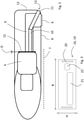
- FIG. 1 An embodiment in the Figures 1 to 3 is shown relates to a robotic vacuum cleaner 1 according to the invention with a housing 2 which delimits an interior space 3 .
- the housing 2 is D-shaped in plan view, but can also be round or have another shape.
- a container 4 is arranged in the interior 3 of the robotic vacuum cleaner 1 , in which dirt particles picked up by the robotic vacuum cleaner 1 are collected.
- the vacuum robot 1 has a fan 5 for generating a suction air flow and a suction mouth 6 on one in the figure 2 indicated bottom surface 7 facing underside 8 of the housing 2 .
- the suction mouth 6 is connected in terms of flow to the fan 5 by means of a suction channel 9 and with the container 4 being interposed, so that dirt particles are picked up at the suction mouth 6 under the effect of the suction air flow and conveyed through the suction channel 9 to the container 4 .
- the vacuum robot 1 according to the Figures 1 to 3 an auxiliary air duct 10 which is also connected in terms of flow to the blower 5 with the interposition of the container 4 .
- the secondary air duct 10 has a suction opening 11 which is located in the area of an outer edge 12 of the housing 2 , in particular in a lower corner area 13 of the housing 2 . Dirt particles located in the corner area 13 of the housing 2 are thus captured at the suction opening 11 by means of a suction air flow of the secondary air duct 10 that is independent of the suction air flow of the suction duct 9 and guided into the housing 2 .
- the auxiliary air duct 10 runs obliquely in a first section starting from the corner region 13 to next to the suction duct 9 and from there parallel next to the suction duct 9 to the container 4 , viewed in plan view.
- the secondary air duct 10 runs from the container 4 in the direction of travel 14 of the vacuum robot 1 and then bends obliquely in the direction of the corner area 13 .
- the robotic vacuum cleaner 1 has an adjustment device 15 with an adjustment element 16 and an adjustment drive, only the adjustment element 16 being visible in the figures.
- the adjusting element 16 is arranged between the container 4 and the suction channel 9 and the secondary air channel 10 and can be adjusted such that a flow cross section 17 of the suction channel 9 and/or a flow cross section 18 of the secondary air channel 10 are changed.
- the adjusting element 16 is in the form of a flat, elongated template 19 with a rectangular cross section and a width B , a height H and a thickness D , with the cross section of the template 19 in figure 3 is shown.
- the template 19 has a guide 20 on each of its two short sides, by means of which it can be moved up and down within the housing 2 in the vertical direction.
- the guides are provided in such a way that the template can be displaced in the horizontal direction.
- the adjustment element 16 has two openings 21 , 22 , of which the first opening 21 corresponds to the flow cross section 17 of the suction channel 9 and the second opening 22 corresponds to the flow cross section 18 of the secondary air channel 10 .
- the flow cross section 17 of the suction channel 9 and/or the flow cross section 18 of the auxiliary air channel 10 is partially or completely closed or opened.
- the robotic vacuum cleaner 1 has a sensor, not shown in the figures, for detecting a distance to at least one wall of a room and a control device 23 for processing the data detected by the sensor and for controlling the adjusting device 15 depending on the data detected by the sensor. If the robotic vacuum cleaner 1 comes close to edge and corner areas, this is detected and the template 19 is adjusted in such a way that the flow cross section 18 of the secondary air duct 10 is released and improved corner and edge cleaning is provided. It goes without saying that distances to furniture or other installations are also detected by the sensor, so that the adjustment element 16 is also adjusted accordingly when such areas approach.
- Two variants can be distinguished here: According to the first variant, the flow cross section 17 of the suction channel 9 is closed by means of the template 19 when driving at corners and edge areas and only the flow cross section 18 of the secondary air channel 10 is released. In this variant, there is a very high suction capacity in the secondary air duct 10 , as a result of which corner and edge cleaning is optimized.
- the flow cross section 17 of the suction channel 9 is closed only to a certain extent when driving in corner and edge areas and the flow cross section 18 of the secondary air channel 10 is released. Consequently, dirt is picked up at both the suction mouth 6 and the suction port 11 , and corner and edge cleaning is improved.
- the vacuum robot 1 Is the vacuum robot 1 outside of corners and edge areas, this is perceived by the sensor and the template 19 is positioned such that the Flow cross section 18 of the secondary air duct 10 is closed.
- the entire power of the blower 5 is available for generating the suction flow in the suction channel 9 , so that there is improved surface cleaning.
- the vacuum robot can also have several sensors.
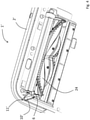
- FIG. 4 Another embodiment of a vacuum robot 1 according to the invention 'is in the Figures 4 to 6 shown.
- the main components of the vacuum robot 1 ' correspond to the main components of the vacuum robot 1 from the Figures 1 to 3 , which is why the same reference numbers are used for these components.
- a brush 24 is arranged in the suction mouth 6 , which helps to pick up dirt.
- a secondary air duct 10 ' which, starting from its suction opening 11 ', leads to the suction mouth 6 and opens out there.
- the secondary air duct 10 ' consists of one duct, one end of which forms the suction opening 11 '.
- the suction opening 11 ' is located in the area of the outer edge 12 of the housing 2 ' of the robotic vacuum cleaner 1 ', again in a lower corner area 13 of the housing 2 , with the secondary air duct 10 ' protruding beyond the housing 2 '. This is good in the figure 6 to recognize.
- the housing 2 ' has a slightly rounded contour when viewed in vertical section, so that a width of the housing 2 ' on the underside 8 of the vacuum robot 1 ' is smaller than a width of the same in a central region 25 located above it.
- the secondary air duct 10 ′ projects beyond the housing 2 ′ on the underside 8 of the vacuum robot 1 ′, it does not project beyond a maximum projection of the housing 2 ′. Because the secondary air duct 10 ' protrudes beyond the housing 2 ' on the underside 8 of the vacuum robot 1 ', the suction opening 11 ' can be as close as possible to the edge, corner areas and furniture of a room.
- the secondary air duct 10 ' opens in the suction mouth 6 , it is not directly connected to the Figures 4 to 6 connected container shown. This means that the dust particles picked up by the suction opening 11 ' are first conveyed into the suction mouth 6 and from there into the container via the suction channel, which is also not shown in the figures. Furthermore, the secondary air duct 10 ' is always active in the present example and its flow cross section 18 ' cannot be closed. Thus, no additional adjusting device is required.
- an adjustment device with an adjustment element can also be provided, which is suitable for closing and opening the flow cross section of the secondary air duct.
- the secondary air duct can be designed to be open towards the floor surface, so that the risk of blockages is counteracted.
- the secondary air duct 10 ' is to be designed in such a way that it tapers in a V-shape from the suction mouth 6 to the suction opening 11 ' in order to ensure an optimal air flow through the duct.
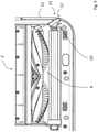
- FIG. 7 to 9 Another embodiment of a vacuum robot 1 according to the invention 'is in the Figures 7 to 9 shown.
- the vacuum robot 1 essentially corresponds to the embodiment according to FIG Figures 4 to 6 with the difference that the secondary air duct 10 protrudes from the housing 2 of the vacuum robot 1. This enables the suction opening 11' to come as close as possible to the edges, corner areas and furniture of a room.
Landscapes
- Engineering & Computer Science (AREA)
- Mechanical Engineering (AREA)
- Electric Vacuum Cleaner (AREA)
- Nozzles For Electric Vacuum Cleaners (AREA)
Abstract
Description
- Die Erfindung betrifft einen Saugroboter gemäß dem Oberbegriff von Anspruch 1.
- Der Saugroboter zur autonomen Reinigung besitzt ein Gehäuse, welches einen Innenraum begrenzt, sowie ein Gebläse zur Erzeugung eines Saugluftstroms. Mittels des Saugluftstroms können auf der Bodenfläche befindliche Schmutzpartikel durch einen am Gehäuse angeordneten Saugmund des Saugroboters mobilisiert und zu einem Behälter transportiert werden, welcher im Innenraum des Gehäuses angeordnet ist. Zur Führung des Saugluftstroms besitzt der Saugroboter einen Saugkanal, der den Saugmund unter Zwischenschaltung des Behälters strömungsmäßig mit dem Gebläse verbindet.
- Saugroboter der vorstehend beschriebenen Art sind in dem Stand der Technik in einer Vielzahl bereits bekannt. Typischerweise besitzen gattungsgemäße Saugroboter einen im Innenraum des Gehäuses angeordneten Fahrantrieb, mittels dessen Rollen, welche üblicherweise an einer Unterseite des Gehäuses angeordnet sind, angetrieben werden können, um den Saugroboter in Bewegung zu versetzen. Um die Reinigung der Bodenfläche zusätzlich zu verbessern, weisen die bekannten Saugroboter üblicherweise eine Hauptbürste auf, welche in einem Bereich nah am Saugmund angeordnet ist. In aller Regel besitzen Saugroboter der vorstehend beschriebenen Art zudem Sensoren, mittels derer in dem Raum befindliche Hindernisse, insbesondere Möbel, erfasst werden können. Mittels einer im Innenraum des Saugroboters angeordneten Steuereinrichtung wird in Abhängigkeit einer durch die Sensoren erfassten Raumgeometrie eine Fahrtrichtung des Saugroboters angepasst.
- Problematisch ist bei den bekannten Saugrobotern, dass in Randbereichen und Ecken des Raums befindliche Schmutzpartikel nicht erfasst werden. Hierzu gibt es im Stand der Technik bereits Lösungen, wie beispielsweise Saugroboter mit rotierenden Seitenbürsten, wobei diese das Problem mit sich bringen, dass die Seitenbürsten einen zusätzlichen Motor benötigen. Ein zusätzlicher Motor bedingt eine erhöhte elektrische Leistung, die wiederum den Akku des Saugroboters belastet und in einer geringeren Akkulaufzeit pro Reinigungsfahrt endet. Auch besteht bei rotierenden Seitenbürsten das Problem, dass sich die Borstenbüschel der Seitenbürsten in tiefen Teppichen verzwirbeln und stecken bleiben. Ferner schränken Seitenbürsten den Saugroboter im Hinblick auf seine Mobilität ein, wie beispielsweise beim Überwinden von Teppichen.
- Des Weiteren ist es aus dem Stand der Technik bekannt, die Randreinigung mit Hilfe eines gesteigerten Luftstroms zu verbessern. Dabei wird die Saugöffnung des Saugroboters so vergrößert, dass sie möglichst weit an eine Außenkante des Saugrobotergehäuses reicht, so dass der Saugstrom bis an den Rand und die Ecken des Raums gelangt und den dort befindlichen Schmutz aufsaugen kann. Allerdings ist die erhöhte Saugleistung aufgrund einer verhältnismäßig großen Saugöffnung in der Regel nicht ausreichend, um ein zufriedenstellendes Ergebnis im Rand- und Eckbereich zu erzielen. Darüber hinaus wird für eine erhöhte Saugleistung eine erhöhte elektrische Leistung des Saugroboters benötigt, was letztlich wieder eine geringere Akkulaufzeit pro Reinigungsfahrt mit sich bringt.
- Es ist daher die Aufgabe der vorliegenden Erfindung, einen Saugroboter bereitzustellen, bei dem die Reinigung von Rand- und Eckbereichen gegenüber dem Stand der Technik optimiert ist.
- Die vorstehende Aufgabe wird ausgehend von einem Saugroboter der eingangs beschriebenen Art mit den Merkmalen des Anspruchs 1 gelöst. Vorteilhafte Ausgestaltungen ergeben sich aus den zugehörigen Unteransprüchen.
- Der erfindungsgemäße Saugroboter ist gekennzeichnet durch einen Nebenluftkanal, der in eine in einem Bereich einer Außenkante des Gehäuses angeordnete Saugöffnung mündet. Dabei ist der Nebenluftkanal unter Zwischenschaltung des Behälters strömungsmäßig mit dem Gebläse verbunden, sodass der mittels des Gebläses erzeugte Saugluftstrom zusätzlich zu dem Saugmund des Saugkanals auch an der Saugöffnung des Nebenluftkanals wirkt und auf diese Weise Schmutzpartikel unter Wirkung des Saugluftstroms an der Saugöffnung des Nebenluftkanals aufnehmbar und mittels des Nebenluftkanals unmittelbar oder mittelbar zu dem Behälter beförderbar sind.
- Der erfindungsgemäße Saugroboter hat viele Vorteile. Die erfindungsgemäß vorgesehene zusätzliche Saugöffnung erhöht gezielt die Reinigungsleistung im Rand- oder Eckbereich eines Raumes, ohne - im Vergleich zu einem vergrößerten Saugmund aus dem Stand der Technik - den Saugmund überproportional vergrößern zu müssen. Demnach ist die zusätzlich benötigte elektrische Energie, die für die Erzeugung eines Saugluftstroms zur Speisung des Saugmundes und der Saugöffnung erforderlich ist, gemäß der vorliegenden Erfindung deutlich geringer, so dass die Akkulaufzeit pro Reinigungsvorgang gegenüber einem Saugroboter ohne verbesserte Rand- und Eckreinigung nur geringfügig sinkt. Gegenüber den aus dem Stand der Technik bekannten Saugrobotern mit verbesserter Rand- und Eckreinigung ist die Akkulaufzeit des erfindungsgemäßen Saugroboters signifikant erhöht. Der Nebenluftkanal kann beispielsweise von einem Rohr gebildet werden, wobei ein im Bereich der Außenkante des Gehäuses befindliches Ende des Rohrs die Saugöffnung bildet. Das Rohr kann einen runden oder einen eckigen Querschnitt aufweisen. Selbstverständlich kann der Nebenluftkanal auch auf andere Weise aufgebaut sein.
- Durch das erfindungsgemäße Vorsehen des Nebenluftkanals kann auf die Anordnung von Seitenbürsten verzichtet werden, wodurch der Verschleiß von Seitenbürsten und der damit in Verbindung stehende Wartungs- und Austauschaufwand entfällt. Ferner entfällt auch die Notwendigkeit eines zusätzlichen Motors für die Seitenbürsten und die Mobilität des erfindungsgemäßen Saugroboters ist gegenüber einem Saugroboter mit Seitenbürsten erhöht.
- Gemäß einer vorteilhaften Ausgestaltung der Erfindung ist vorgesehen, dass der Nebenluftkanal in den Saugmund mündet, was bedeutet, dass die Schmutzpartikel von dem Nebenluftkanal mittelbar zu dem Behälter befördert werden, nämlich unter Zwischenschaltung des Saugmundes und des Saugkanals. Anders ausgedrückt werden die Schmutzpartikel an der Saugöffnung erfasst und über den Nebenluftkanal, den Saugmund und den Saugkanal zu dem Behälter befördert. Diese Ausgestaltung erfordert wenige bauliche Änderungen gegenüber einem herkömmlichen Saugroboter ohne Rand- und Eckreinigung, so dass sich der erfindungsgemäße Saugroboter durch eine einfache und günstige Herstellung auszeichnet.
- Eine vorzugsweise Ausgestaltung der Erfindung sieht vor, dass der Nebenluftkanal auf einer zu der Bodenfläche weisenden Seite offen ausgebildet ist. Hierdurch wird der Gefahr eines Verstopfens des Nebenluftkanals durch Schmutz oder durch kleine Gegenstände entgegengewirkt.
- Gemäß einer besonders vorteilhaften Weiterentwicklung des erfindungsgemäßen Saugroboters mündet der Nebenluftkanal nicht in den Saugkanal, sondern direkt in den Behälter. Das heißt, dass der Nebenluftkanal unmittelbar zu dem Behälter führt, also direkt und ohne Zwischenschaltung anderer Komponenten. Demnach besitzt der Behälter - im Gegensatz zu der weiter oben beschriebenen "mittelbaren" Alternative - zwei Verbindungsquerschnitte, nämlich einen Verbindungsquerschnitt zu dem Saugkanal und einen Verbindungsquerschnitt zu dem Nebenluftkanal. Diese Ausgestaltung hat den Vorteil, dass der Nebenluftkanal im Bedarfsfall direkt an dem Behälter strömungstechnisch zugeschaltet oder abgeschaltet werden kann, wodurch Strömungsverluste vermeidbar sind.
- Den erfindungsgemäßen Saugroboter weiter ausgestaltend weist dieser mindestens eine Verstelleinrichtung auf, mindestens ein Verstellelement und einen Verstellantrieb umfasst, wobei mittels des Verstellelements ein Strömungsquerschnitt des Saugkanals und/oder ein Strömungsquerschnitt des Nebenluftkanals zumindest teilweise, vorzugsweise vollständig, verschließbar und/oder freigebbar ist. Demnach kann in Abhängigkeit davon, wo die Saugleistung benötigt wird, auf die Strömungsquerschnitte des Saugkanals oder des Nebenluftkanals Einfluss genommen werden.
- Für den Fall, dass der Nebenluftkanal im Behälter mündet, kann ein Verstellelement vorgesehen sein, das den Strömungsquerschnitt des Nebenluftkanals verschließen beziehungsweise freigeben kann. In Bereichen von Ecken und Rändern kann der Strömungsquerschnitt des Nebenluftkanals zusätzlich freigegeben werden, wohingegen er im Flächenbereich verschlossen wird. So wird die zur Verfügung stehende Saugleistung des Saugroboters individuell an die vorliegenden Gegebenheiten angepasst.
- Wird die Verstelleinrichtung bei Saugrobotern vorgesehen, dessen Nebenluftkanal in dem Behälter mündet, sind andere Möglichkeiten eröffnet: Beispielsweise kann bei Fahrten an Ecken- und Randbereichen vorgesehen sein, dass der Strömungsquerschnitt des Saugkanals gänzlich von einem entsprechenden Verstellelement verschlossen wird, so dass der gesamte Saugluftstrom des Gebläses durch den Nebenluftkanal strömt und die Saugleistung des Saugroboters im Ecken- und Randbereich optimiert ist. Bei der Reinigung außerhalb der Eckenund Randbereiche ist der Strömungsquerschnitt des Nebenluftkanals durch ein entsprechendes Verstellelement verschließbar und der Strömungsquerschnitt des Saugkanals freigebbar, so dass dann eine verbesserte Flächenreinigung gegeben ist. Zu Randbereichen eines Raums können ebenfalls Bereiche von Trennwänden oder anderen Wandabschnitten gezählt werden, genauso wie Mobiliar.
- Alternativ kann auch vorgesehen sein, dass bei Fahrten an Ecken- und Randbereichen der Strömungsquerschnitt des Saugkanals nur teilweise verschlossen und der Strömungsquerschnitt des Nebenluftkanals freigegeben wird, so dass durch beide Kanäle Schmutz aufgenommen wird.
- Als Verstellelement kann beispielsweise eine bewegliche Klappe oder ein Schieber dienen.
- Die beschriebene Ausgestaltung ist dann zudem besonders von Vorteil, wenn das Verstellelement von einer an dem Behälter angeordneten Schablone gebildet ist, die zwischen einer Nebenposition und einer Hauptposition verstellbar ist, wobei die Schablone bei Vorliegen in ihrer Hauptposition den Strömungsquerschnitt des Saugkanals und bei Vorliegen in ihrer Nebenposition den Strömungsquerschnitt des Nebenluftkanals zumindest teilweise, vorzugsweise vollständig, freigibt. Vorteilhafterweise kann das Verstellelement zudem mindestens eine Zwischenposition, vorzugsweise eine beliebige Vielzahl von Zwischenpositionen, zwischen der Hauptposition und der Nebenposition einnehmen. Vorteil der erfindungsgemäßen Schablone ist, dass sie als einzelnes Bauteil zur Einstellung beider Strömungsquerschnitte herangezogen werden kann.
- Dabei ist es besonders zweckmäßig, wenn die Schablone möglichst flach, nach Art eines Blechs, ausgebildet ist, wobei eine Mittelebene der Schablone parallel zu einer Wandung des Behälters verläuft. Eine derartige Schablone führt nur zu einem minimalen Platzverlust innerhalb des Saugroboters. Die Schablone kann aus einem Kunststoff, einem Karton oder anderen Materialen bestehen, die für Luft zumindest im Wesentlichen, vorzugsweise vollständig, undurchlässig sind. Vorteilhafterweise besitzt die Schablone einen Ausschnitt in Form einer Öffnung, die dem Strömungsquerschnitt des Saugkanals entspricht und einen Ausschnitt, der dem Strömungsquerschnitt des Nebenluftkanals entspricht. Das Verstellelement ist mittels des Verstellantriebs parallel zu der Mittelebene der Schablone verschiebbar. Als praktikabel hat sich die Verschiebung der Schablone in horizontale oder in vertikale Richtung gezeigt.
- Durch Verschieben der Schablone in die Hauptposition ist die Schablone derart positioniert, dass der dem Saugkanal zugeordnete Ausschnitt mit dem Strömungsquerschnitt des Saugkanals zusammenfällt, so dass der Saugkanal vollständig freigegeben ist. In dieser Position versperrt die Schablone den Strömungsquerschnitt des Nebenluftkanals. Befindet sich die Schablone in der Nebenposition fällt der dem Nebenluftkanal entsprechende Ausschnitt mit dem Strömungsquerschnitt des Nebenluftkanals zusammen und der Nebenluftkanal ist vollständig freigegeben. In der Nebenposition kann die Schablone - je nach gewünschter Ausführungsform - entweder den Strömungsquerschnitt des Saugkanals vollständig oder aber nur teilweise versperren. Auch ist es denkbar, dass der Strömungsquerschnitt bei Vorliegen der Schablone in ihrer Nebenposition vollständig freigegeben ist.
- Gemäß einer vorzugsweisen Ausgestaltung der Erfindung besitzt der Saugroboter mindestens einen Sensor zur Erfassung von Daten betreffend eine Entfernung einer Außenkante des Saugroboters zu mindestens einer Wand des Raums sowie eine Steuerungseinrichtung zur Verarbeitung der erfassten Daten und zur Ansteuerung der Verstelleinrichtung in Abhängigkeit von den erfassten Daten. Auf diese Weise läuft die Einstellung des Verstellelements vollständig automatisch ab: Erfasst der Sensor eine Entfernung zu einer Wand, die auf einen ausreichenden Abstand zu der Wand schließen lässt, verbleibt die Schablone in der Hauptposition und die Staubpartikel werden über den Saugmund erfasst. Sobald der Sensor jedoch eine Entfernung zu einer Wand misst, die darauf schließen lässt, dass der Saugroboter an einem Rand des Raumes angekommen ist, erfolgt eine entsprechende Datenverarbeitung in der Steuerungseinrichtung sowie eine entsprechende Ansteuerung des Verstellelements, so dass der Strömungsquerschnitt des Nebenluftkanals freigegeben wird.
- Detektiert der mindestens eine Sensor eine kurze Entfernung zu zwei Wänden, so nähert sich der Saugroboter einem Eckenbereich.
- Vorteilhafterweise kann die Steuerungseinrichtung des Saugroboters auf Grundrissdaten des Raumes zugreifen, um die Reinigungsfahrt in zwei Abschnitte zu unterteilen, nämlich in einen Abschnitt zur Reinigung der Ecken- und Randbereiche und einen Abschnitt zur Reinigung eines Innenbereiches. Auf diese Weise ist eine Häufigkeit eines Wechsels des Verstellelements von der Hauptposition in die Nebenposition und umgekehrt minimiert.
- Es ist gemäß einer vorzugsweisen Ausgestaltung der Erfindung vorgesehen, dass der Nebenluftkanal über das Gehäuse hinaus übersteht, so dass die Saugöffnung so nah wie möglich an Rand- und Eckenbereiche herangelangen kann.
- Diesbezüglich ist es ferner von Vorteil, wenn der Nebenluftkanal zumindest teilweise aus Kunststoff oder Gummi besteht und nicht starr sondern flexibel ausgeführt ist, so dass eine Beschädigung von der Umgebung, wie beispielsweise Wänden oder Mobiliar, vermieden wird und der Nebenluftkanal an Hindernissen umgeklappt werden bzw. ausweichen kann. In einer alternativen Ausführungsform kann der Nebenluftkanal zumindest teilweise auch aus anderen flexiblen Materialien ausgeführt sein.
- Ebenfalls wird die zugrundeliegende Aufgabe mittels eines Verfahrens mit den Merkmalen des Anspruchs 10 gelöst. Das erfindungsgemäße Verfahren ist dadurch gekennzeichnet, dass mittels eines Sensors Daten betreffend eine Entfernung einer Außenkante des Saugroboters zu mindestens einer Wand des Raums erfasst werden und mittels einer Steuerungseinrichtung die erfassten Daten verarbeitet werden. Ferner steuert die Steuerungseinrichtung die Verstelleinrichtung in Abhängigkeit der erfassten Daten an, so dass das Verstellelement derart verstellt wird, dass ein Strömungsquerschnitt des Saugkanals und/oder ein Strömungsquerschnitt des Nebenluftkanals des Saugroboters zumindest teilweise verschlossen und/oder freigegeben wird bzw. werden.
- Das erfindungsgemäße Verfahren ist mittels des erfindungsgemäßen Haushalts- oder Gewerbegeräts besonders einfach durchführbar. Die sich hierdurch ergebenden Vorteile sind vorstehend bereits dargelegt.
- Zwei Ausführungsbeispiele der Erfindung sind in den Zeichnungen rein schematisch dargestellt und werden nachfolgend näher beschrieben. Es zeigt:
- Figur 1
- eine Draufsicht auf einen erfindungsgemäßen Saugroboter,
- Figur 2
- einen Schnitt durch den Saugroboter gemäß
Figur 1 , - Figur 3
- eine Frontansicht eines Verstellelements aus
Figur 1 , - Figur 4
- eine dreidimensionale Unteransicht eines weiteren erfindungsgemäßen Saugroboters,
- Figur 5
- eine Unteransicht des Saugroboters nach
Figur 4 , - Figur 6
- einen Ausschnitt einer Frontansicht des Saugroboters gemäß
Figur 4 . - Figur 7
- eine dreidimensionale Unteransicht eines weiteren erfindungsgemäßen Saugroboters,
- Figur 8
- eine Unteransicht des Saugroboter nach
Figur 7 , und - Figur 9
- einen Ausschnitt einer Frontansicht des Saugroboters gemäß
Figur 7 . - Ein Ausführungsbeispiel, das in den
Figuren 1 bis 3 gezeigt ist, betrifft einen erfindungsgemäßen Saugroboter 1 mit einem Gehäuse 2, das einen Innenraum 3 begrenzt. Das Gehäuse 2 ist in der Draufsicht D-förmig, kann aber auch rund oder andersförmig ausgebildet sein. Im Innenraum 3 des Saugroboters 1 ist ein Behälter 4 angeordnet, in dem vom Saugroboter 1 erfasste Schmutzpartikel gesammelt werden. Ferner besitzt der Saugroboter 1 ein Gebläse 5 zur Erzeugung eines Saugluftstroms sowie einen Saugmund 6 an einer in derFigur 2 angedeuteten Bodenfläche 7 zugewandten Unterseite 8 des Gehäuses 2. Der Saugmund 6 ist mittels eines Saugkanals 9 und unter Zwischenschaltung des Behälters 4 strömungsmäßig mit dem Gebläse 5 verbunden, so dass Schmutzpartikel unter Wirkung des Saugluftstroms an dem Saugmund 6 aufgenommen und durch den Saugkanal 9 zu dem Behälter 4 befördert werden. - Erfindungsgemäß besitzt der Saugroboter 1 gemäß den
Figuren 1 bis 3 einen Nebenluftkanal 10, der ebenfalls unter Zwischenschaltung des Behälters 4 strömungsmäßig mit dem Gebläse 5 verbunden ist. Der Nebenluftkanal 10 weist eine Saugöffnung 11 auf, die sich im Bereich einer Außenkante 12 des Gehäuses 2, insbesondere in einem unteren Eckbereich 13 des Gehäuses 2, befindet. Im Eckbereich 13 des Gehäuses 2 befindliche Schmutzpartikel werden somit mittels eines von dem Saugluftstrom des Saugkanals 9 unabhängigen Saugluftstroms des Nebenluftkanals 10 an der Saugöffnung 11 erfasst und in das Gehäuse 2 geleitet. - Der Nebenluftkanal 10 verläuft in der Draufsicht betrachtet in einem ersten Abschnitt schräg ausgehend von dem Eckbereich 13 bis neben den Saugkanal 9 und von dort parallel neben dem Saugkanal 9 bis hin zum Behälter 4. Anders ausgedrückt verläuft der Nebenluftkanal 10 ausgehend von dem Behälter 4 in Fahrtrichtung 14 des Saugroboters 1 und knickt dann schräg in Richtung zu dem Eckbereich 13 ab.
- Der erfindungsgemäße Saugroboter 1 besitzt eine Verstelleinrichtung 15 mit einem Verstellelement 16 und einem Verstellantrieb, wobei in den Figuren lediglich das Verstellelement 16 zu erkennen ist. Das Verstellelement 16 ist zwischen dem Behälter 4 und dem Saugkanal 9 sowie dem Nebenluftkanal 10 angeordnet und kann so verstellt werden, dass ein Strömungsquerschnitt 17 des Saugkanals 9 und/oder ein Strömungsquerschnitt 18 des Nebenluftkanals 10 verändert werden. Im vorliegenden Beispiel ist das Verstellelement 16 in Form einer flachen, langgestreckten Schablone 19 mit rechteckigem Querschnitt und einer Breite B, einer Höhe H und einer Dicke D ausgebildet, wobei der Querschnitt der Schablone 19 in
Figur 3 gezeigt ist. Die Schablone 19 weist an ihren beiden kurzen Seiten jeweils eine Führung 20 auf, mittels des sie innerhalb des Gehäuse 2 in vertikale Richtung auf und ab bewegt werden kann. Alternativ ist es auch denkbar, dass die Führungen so vorgesehen sind, dass die Schablone in horizontale Richtung verschiebbar ist. - Das Verstellelement 16 weist zwei Öffnungen 21, 22 auf, von denen die erste Öffnung 21 dem Strömungsquerschnitt 17 des Saugkanals 9 und die zweite Öffnung 22 dem Strömungsquerschnitt 18 des Nebenluftkanals 10 entspricht. In Abhängigkeit von der jeweiligen Position des Verstellelements 16 wird der Strömungsquerschnitt 17 des Saugkanals 9 und/oder der Strömungsquerschnitt 18 des Nebenluftkanals 10 teilweise oder gänzlich verschlossen oder freigegeben.
- Ferner besitzt der erfindungsgemäße Saugroboter 1 einen nicht in den Figuren dargestellten Sensor zur Erfassung einer Entfernung zu mindestens einer Wand eines Raumes sowie eine Steuerungseinrichtung 23 zur Verarbeitung der von dem Sensor erfassten Daten und zur Ansteuerung der Verstelleinrichtung 15 in Abhängigkeit von den erfassten Daten des Sensors. Gelangt der Saugroboter 1 in die Nähe von Rand- und Eckbereichen, wird dies erfasst und die Schablone 19 so verstellt, dass der Strömungsquerschnitt 18 des Nebenluftkanals 10 freigegeben ist und eine verbesserte Ecken- und Randreinigung gegeben ist. Es versteht sich, dass ebenfalls Entfernungen zu Mobiliar oder anderen Einbauten von dem Sensor erfasst werden, so dass das Verstellelement 16 bei Annäherung derartiger Bereiche ebenfalls entsprechend verstellt wird.
- Hierbei können zwei Varianten unterschieden werden:
Gemäß der ersten Variante wird der Strömungsquerschnitt 17 des Saugkanals 9 bei Fahrten an Ecken- und Randbereichen mittels der Schablone 19 verschlossen und nur der Strömungsquerschnitt 18 des Nebenluftkanals 10 freigegeben. Bei dieser Variante besteht eine sehr hohe Saugleistung in dem Nebenluftkanal 10, wodurch die Ecken- und Randreinigung optimiert ist. - Gemäß der zweiten Variante wird der Strömungsquerschnitt 17 des Saugkanals 9 bei Fahrten an Ecken- und Randbereichen nur zu einem gewissen Anteil geschlossen und der Strömungsquerschnitt 18 des Nebenluftkanals 10 freigegeben. Folglich wird sowohl am Saugmund 6 als auch an der Saugöffnung 11 Schmutz aufgenommen und die Ecken- und Randreinigung ist verbessert.
- Befindet sich der Saugroboter 1 außerhalb von Ecken- und Randbereichen wird dies von dem Sensor wahrgenommen und die Schablone 19 derart positioniert, dass der Strömungsquerschnitt 18 des Nebenluftkanals 10 geschlossen ist. Die gesamte Leistung des Gebläses 5 steht zur Erzeugung des Saugstroms in dem Saugkanal 9 zur Verfügung, so dass eine verbesserte Flächenreinigung gegeben ist. Es versteht sich, dass der Saugroboter ebenfalls mehrere Sensoren besitzen kann.
- Ein weiteres Ausführungsbeispiel für einen erfindungsgemäßen Saugroboter 1' ist in den
Figuren 4 bis 6 gezeigt. Die Hauptbestandteile des Saugroboters 1' entsprechen den Hauptbestandteilen des Saugroboters 1 aus denFiguren 1 bis 3 , weshalb für diese Bestandteile dieselben Bezugszeichen benutzt werden. In derFigur 4 ist zu erkennen, dass in dem Saugmund 6 eine Bürste 24 angeordnet ist, die die Aufnahme von Schmutz unterstützt. - Im Unterschied zu dem Saugroboter 1 gemäß den
Figuren 1 bis 3 besitzt der Saugroboter 1' gemäß denFiguren 4 bis 6 einen Nebenluftkanal 10', der ausgehend von seiner Saugöffnung 11' zu dem Saugmund 6 führt und dort mündet. Der Nebenluftkanal 10' besteht aus einem Kanal, wobei ein Ende die Saugöffnung 11' bildet. Die Saugöffnung 11' befindet sich im Bereich der Außenkante 12 des Gehäuses 2' des Saugroboters 1', abermals in einem unteren Eckbereich 13 des Gehäuses 2, wobei der Nebenluftkanal 10' über das Gehäuse 2' hervorsteht. Dies ist gut in derFigur 6 zu erkennen. In derFigur 6 ist ebenfalls zu erkennen, dass das Gehäuse 2' im Vertikalschnitt betrachtet eine leicht gerundete Kontur besitzt, so dass eine Breite des Gehäuses 2' an der Unterseite 8 des Saugroboters 1' kleiner ist als eine Breite desselben in einem darüber befindlichen mittleren Bereich 25. Somit steht der Nebenluftkanal 10' zwar an der Unterseite 8 des Saugroboters 1' über das Gehäuse 2' über, nicht jedoch über eine maximale Ausladung des Gehäuses 2'. Dadurch dass der Nebenluftkanal 10' über das Gehäuse 2' an der Unterseite 8 des Saugroboters 1' vorsteht, ist eine maximale Annäherung der Saugöffnung 11' an Rand-, Eckbereiche und Mobiliar eines Raums möglich. - Da der Nebenluftkanal 10' im Saugmund 6 mündet, ist er mittelbar mit dem nicht in den
Figuren 4 bis 6 gezeigten Behälter verbunden. Dies bedeutet, dass die von der Saugöffnung 11' aufgenommenen Staubpartikel zunächst in den Saugmund 6 und von dort über den ebenfalls nicht in den Figuren gezeigten Saugkanal in den Behälter befördert werden. Ferner ist der Nebenluftkanal 10' im vorliegenden Beispiel immer aktiv und sein Strömungsquerschnitt 18' ist nicht verschließbar. Somit wird auch keine zusätzliche Verstelleinrichtung benötigt. - Alternativ kann jedoch auch eine Verstelleinrichtung mit Verstellelement vorgesehen sein, das zum Schließen und Öffnen des Strömungsquerschnittes des Nebenluftkanals geeignet ist.
- Der Nebenluftkanal kann in einer weiteren Alternative zu der Bodenfläche hin geöffnet ausgebildet sein, so dass einer Gefahr von Verstopfungen entgegengewirkt wird.
- Weiterhin ist der Nebenluftkanal 10' so auszuführen, dass dieser vom Saugmund 6 zum Saugöffnung 11' v-förmig zuläuft, um eine optimale Luftströmung durch den Kanal zu gewährleisten.
- Ein weiteres Ausführungsbeispiel für einen erfindungsgemäßen Saugroboter 1' ist in den
Figuren 7 bis 9 gezeigt. Der Saugroboter 1 entspricht im Wesentlichen der Ausführungsform gemäß denFiguren 4 bis 6 mit dem Unterschied, dass der Nebenluftkanal 10 von dem Gehäuse 2 des Saugroboters 1 hervorsteht. Dies ermöglicht eine maximale Annäherung der Saugöffnung 11' an Rand-, Eckbereiche und Mobiliar eines Raums. -
- 1
- Saugroboter
- 2
- Gehäuse
- 3
- Innenraum
- 4
- Behälter
- 5
- Gebläse
- 6
- Saugmund
- 7
- Bodenfläche
- 8
- Unterseite
- 9
- Saugkanal
- 10
- Nebenluftkanal
- 11
- Saugöffnung
- 12
- Außenkante
- 13
- Eckbereich
- 14
- Fahrtrichtung
- 15
- Verstelleinrichtung
- 16
- Verstellelement
- 17
- Strömungsquerschnitt Saugkanal
- 18
- Strömungsquerschnitt Nebenluftkanal
- 19
- Schablone
- 20
- Führung
- 21
- Erste Öffnung
- 22
- Zweite Öffnung
- 23
- Steuerungseinrichtung
- 24
- Bürste
- 25
- Mittlerer Bereich
- B
- Breite
- H
- Höhe
- D
- Dicke
Claims (10)
- Saugroboter (1, 1') zur autonomen Reinigung von Bodenflächen (7) eines Raums umfassend- ein Gehäuse (2, 2'), welches einen Innenraum (3) begrenzt,- einen im Innenraum (3) des Gehäuses (2, 2') angeordneten Behälter (4) zur Aufnahme von Schmutzpartikeln,- ein Gebläse (5) zur Erzeugung eines Saugluftstroms,- mindestens einen am Gehäuse (2, 2') angeordneten Saugmund (6) sowie- einen Saugkanal (9), der den Saugmund (6) unter Zwischenschaltung des Behälters (4) strömungsmäßig mit dem Gebläse (5) verbindet,wobei Schmutzpartikel unter Wirkung des Saugluftstroms an dem Saugmund (6) aufnehmbar und mittels des Saugkanals (9) zu dem Behälter (4) beförderbar sind,
gekennzeichnet, durcheinen Nebenluftkanal (10, 10'), der in eine in einem Bereich einer Außenkante (12) des Gehäuses (2) angeordnete Saugöffnung (11, 11') mündet,wobei der Nebenluftkanal (10, 10') unter Zwischenschaltung des Behälters (4) strömungsmäßig mit dem Gebläse (5) verbunden ist, sodass der mittels des Gebläses (5) erzeugte Saugluftstrom zusätzlich zu dem Saugmund (6) des Saugkanals (9) auch an der Saugöffnung (11, 11') des Nebenluftkanals (10, 10') wirkt und auf diese Weise Schmutzpartikel unter Wirkung des Saugluftstroms an der Saugöffnung (11, 11') des Nebenluftkanals (10, 10') aufnehmbar und mittels des Nebenluftkanals (10, 10') unmittelbar oder mittelbar zu dem Behälter (4) beförderbar sind. - Saugroboter (1') nach Anspruch 1, dadurch gekennzeichnet, dass der Nebenluftkanal (10') in den Saugmund (6) mündet.
- Saugroboter (1') nach Anspruch 1 oder 2, dadurch gekennzeichnet, dass der Nebenluftkanal (10') auf einer zu der Bodenfläche (7) weisenden Seite offen ausgebildet ist.
- Saugroboter (1) nach Anspruch 1, dadurch gekennzeichnet, dass der Nebenluftkanal (10) in den Behälter (4) mündet.
- Saugroboter (1, 1') nach einem der Ansprüche 1 bis 4, gekennzeichnet durch mindestens eine Verstelleinrichtung (15), umfassend mindestens ein Verstellelement (16) und einen Verstellantrieb, wobei mittels des Verstellelements (16) ein Strömungsquerschnitt (17) des Saugkanals (9) und/oder ein Strömungsquerschnitt (18, 18') des Nebenluftkanals (10, 10') zumindest teilweise, vorzugsweise vollständig, verschließbar und/oder freigebbar ist.
- Saugroboter (1, 1') nach Anspruch 5, dadurch gekennzeichnet, dass das Verstellelement (16) von einer an dem Behälter (4) angeordneten Schablone (19) gebildet ist, die zwischen einer Nebenposition und einer Hauptposition verstellbar ist, wobei die Schablone (19) bei Vorliegen in ihrer Hauptposition den Strömungsquerschnitt (17) des Saugkanals (9) und bei Vorliegen in ihrer Nebenposition den Strömungsquerschnitt (8) des Nebenluftkanals (10, 10') zumindest teilweise, vorzugsweise vollständig, freigibt.
- Saugroboter (1, 1') nach Anspruch 5 oder 6, gekennzeichnet durch mindestens einen Sensor zur Erfassung von Daten betreffend eine Entfernung einer Außenkante des Saugroboters (1, 1') zu mindestens einer Wand des Raums sowie durch eine Steuerungseinrichtung (23) zur Verarbeitung der erfassten Daten und zur Ansteuerung der Verstelleinrichtung (15) in Abhängigkeit von den erfassten Daten.
- Saugroboter, dadurch gekennzeichnet, dass der Nebenluftkanal (10') über das Gehäuse (2') hinaus übersteht.
- Saugroboter, dadurch gekennzeichnet, dass der Nebenluftkanal (10, 10') zumindest teilweise aus Kunststoff oder Gummi besteht.
- Verfahren zum Betrieb eines Saugroboters (1, 1') nach einem der vorhergehenden Ansprüche 7 bis 9, wobei- mittels eines Sensors Daten betreffend eine Entfernung einer Außenkante des Saugroboters (1, 1') zu mindestens einer Wand des Raums erfasst werden;- mittels einer Steuerungseinrichtung (23) die erfassten Daten verarbeitet werden und die Steuerungseinrichtung (23) die Verstelleinrichtung (15) in Abhängigkeit der erfassten Daten ansteuert, so dass das Verstellelement (16) derart verstellt wird, dass ein Strömungsquerschnitt (17) des Saugkanals (9) und/oder ein Strömungsquerschnitt (18) des Nebenluftkanals (10, 10') des Saugroboters (1, 1') zumindest teilweise verschlossen und/oder freigegeben wird bzw. werden.
Applications Claiming Priority (1)
| Application Number | Priority Date | Filing Date | Title |
|---|---|---|---|
| DE102020124602.1A DE102020124602A1 (de) | 2020-09-22 | 2020-09-22 | Saugroboter |
Publications (3)
| Publication Number | Publication Date |
|---|---|
| EP3970589A1 true EP3970589A1 (de) | 2022-03-23 |
| EP3970589B1 EP3970589B1 (de) | 2025-02-19 |
| EP3970589C0 EP3970589C0 (de) | 2025-02-19 |
Family
ID=77563920
Family Applications (1)
| Application Number | Title | Priority Date | Filing Date |
|---|---|---|---|
| EP21193896.4A Active EP3970589B1 (de) | 2020-09-22 | 2021-08-31 | Saugroboter |
Country Status (2)
| Country | Link |
|---|---|
| EP (1) | EP3970589B1 (de) |
| DE (1) | DE102020124602A1 (de) |
Citations (3)
| Publication number | Priority date | Publication date | Assignee | Title |
|---|---|---|---|---|
| EP3178362A1 (de) * | 2014-08-07 | 2017-06-14 | Samsung Electronics Co., Ltd. | Roboterreiniger |
| WO2018217980A1 (en) * | 2017-05-25 | 2018-11-29 | Sharkninja Operating Llc | Robotic cleaner with dual cleaning rollers |
| EP3679848A1 (de) * | 2017-09-04 | 2020-07-15 | Chiba Institute of Technology | Selbstangetriebener staubsauger |
-
2020
- 2020-09-22 DE DE102020124602.1A patent/DE102020124602A1/de not_active Withdrawn
-
2021
- 2021-08-31 EP EP21193896.4A patent/EP3970589B1/de active Active
Patent Citations (3)
| Publication number | Priority date | Publication date | Assignee | Title |
|---|---|---|---|---|
| EP3178362A1 (de) * | 2014-08-07 | 2017-06-14 | Samsung Electronics Co., Ltd. | Roboterreiniger |
| WO2018217980A1 (en) * | 2017-05-25 | 2018-11-29 | Sharkninja Operating Llc | Robotic cleaner with dual cleaning rollers |
| EP3679848A1 (de) * | 2017-09-04 | 2020-07-15 | Chiba Institute of Technology | Selbstangetriebener staubsauger |
Also Published As
| Publication number | Publication date |
|---|---|
| EP3970589B1 (de) | 2025-02-19 |
| DE102020124602A1 (de) | 2022-03-24 |
| EP3970589C0 (de) | 2025-02-19 |
Similar Documents
| Publication | Publication Date | Title |
|---|---|---|
| EP3310233B1 (de) | Saugdüse für einen staubsauger | |
| EP3517012B1 (de) | Basisstation für einen staubsauger | |
| EP3973838A1 (de) | Filtereinrichtung und verfahren zu deren abreinigung | |
| DE202015008649U1 (de) | Staubsammler für Staubsauger | |
| EP3669733B1 (de) | Basisstation für selbsttätig verfahrbares haushaltsgerät | |
| DE10316083A1 (de) | Kantenreinigungssystem für Vakuumreiniger | |
| EP2893860B1 (de) | Bodenpflegegerät mit einer angetriebenen Bürstenwalze | |
| EP3095368B1 (de) | Hartbodendüse für grobgut und feinstaubaufnahme | |
| EP3409168A1 (de) | Eckenreinigungsmodul für modular aufgebaute reinigungsroboter | |
| DE102023116781A1 (de) | Vorfiltervorrichtungen und ventile für einen industriellen staubabscheider | |
| DE102017208960A1 (de) | Staubsauger mit einem motorisch betriebenen Dichtmittel | |
| DE102013104255A1 (de) | Verfahren zum Betrieb einer Staubsammelkammer sowie Staubsammelkammer für einen elektrisch betriebenen Staubsauger | |
| EP3970589B1 (de) | Saugroboter | |
| EP3095369A1 (de) | Saugdüse zur aufnahme von grobgut und feinstaub | |
| EP3984429B1 (de) | Staubsauger und verfahren zum betrieb eines staubsaugers | |
| DE102015105060B4 (de) | Reinigungsgerät, insbesondere Staubsauger oder Vorsatzgerät eines Staubsaugers | |
| WO2023117422A1 (de) | Filterabreinigungseinheit, staubsauger und verfahren zur abreinigung eines filters in einem staubsauger | |
| DE102018129114A1 (de) | Verfahren zum Betrieb eines Staubsaugersystems sowie Staubsaugersystem | |
| EP3741276B1 (de) | Staubsauger zur reinigung von bodenflächen | |
| EP3763271B1 (de) | Bodendüse für eine saugeinrichtung zur reinigung und pflege von bodenflächen | |
| DE202021106399U1 (de) | Vorsatzgerät für ein Haushaltsreinigungsgerät und Systeme zum Reinigen von Teppichböden | |
| EP2534990A2 (de) | Bodendüse für einen Staubsauger und Staubsauger mit einer solchen Bodendüse | |
| EP3808241B1 (de) | Saugroboter zur autonomen reinigung von bodenflächen eines raums | |
| DE202025104021U1 (de) | Seitenbürste, Reinigungskomponente, Reinigungsvorrichtung, Reinigungsbasisstation und Reinigungssystem | |
| EP2123204A2 (de) | Vorrichtung zur Regulierung des Saugluftstroms eines Saugers |
Legal Events
| Date | Code | Title | Description |
|---|---|---|---|
| PUAI | Public reference made under article 153(3) epc to a published international application that has entered the european phase |
Free format text: ORIGINAL CODE: 0009012 |
|
| STAA | Information on the status of an ep patent application or granted ep patent |
Free format text: STATUS: THE APPLICATION HAS BEEN PUBLISHED |
|
| AK | Designated contracting states |
Kind code of ref document: A1 Designated state(s): AL AT BE BG CH CY CZ DE DK EE ES FI FR GB GR HR HU IE IS IT LI LT LU LV MC MK MT NL NO PL PT RO RS SE SI SK SM TR |
|
| STAA | Information on the status of an ep patent application or granted ep patent |
Free format text: STATUS: REQUEST FOR EXAMINATION WAS MADE |
|
| 17P | Request for examination filed |
Effective date: 20220923 |
|
| RBV | Designated contracting states (corrected) |
Designated state(s): AL AT BE BG CH CY CZ DE DK EE ES FI FR GB GR HR HU IE IS IT LI LT LU LV MC MK MT NL NO PL PT RO RS SE SI SK SM TR |
|
| GRAP | Despatch of communication of intention to grant a patent |
Free format text: ORIGINAL CODE: EPIDOSNIGR1 |
|
| STAA | Information on the status of an ep patent application or granted ep patent |
Free format text: STATUS: GRANT OF PATENT IS INTENDED |
|
| INTG | Intention to grant announced |
Effective date: 20241125 |
|
| GRAS | Grant fee paid |
Free format text: ORIGINAL CODE: EPIDOSNIGR3 |
|
| GRAA | (expected) grant |
Free format text: ORIGINAL CODE: 0009210 |
|
| STAA | Information on the status of an ep patent application or granted ep patent |
Free format text: STATUS: THE PATENT HAS BEEN GRANTED |
|
| AK | Designated contracting states |
Kind code of ref document: B1 Designated state(s): AL AT BE BG CH CY CZ DE DK EE ES FI FR GB GR HR HU IE IS IT LI LT LU LV MC MK MT NL NO PL PT RO RS SE SI SK SM TR |
|
| REG | Reference to a national code |
Ref country code: GB Ref legal event code: FG4D Free format text: NOT ENGLISH |
|
| REG | Reference to a national code |
Ref country code: CH Ref legal event code: EP |
|
| REG | Reference to a national code |
Ref country code: IE Ref legal event code: FG4D Free format text: LANGUAGE OF EP DOCUMENT: GERMAN |
|
| REG | Reference to a national code |
Ref country code: DE Ref legal event code: R096 Ref document number: 502021006683 Country of ref document: DE |
|
| U01 | Request for unitary effect filed |
Effective date: 20250219 |
|
| U07 | Unitary effect registered |
Designated state(s): AT BE BG DE DK EE FI FR IT LT LU LV MT NL PT RO SE SI Effective date: 20250225 |
|
| REG | Reference to a national code |
Ref country code: GB Ref legal event code: 746 Effective date: 20250414 |
|
| PG25 | Lapsed in a contracting state [announced via postgrant information from national office to epo] |
Ref country code: RS Free format text: LAPSE BECAUSE OF FAILURE TO SUBMIT A TRANSLATION OF THE DESCRIPTION OR TO PAY THE FEE WITHIN THE PRESCRIBED TIME-LIMIT Effective date: 20250519 |
|
| PG25 | Lapsed in a contracting state [announced via postgrant information from national office to epo] |
Ref country code: PL Free format text: LAPSE BECAUSE OF FAILURE TO SUBMIT A TRANSLATION OF THE DESCRIPTION OR TO PAY THE FEE WITHIN THE PRESCRIBED TIME-LIMIT Effective date: 20250219 |
|
| PG25 | Lapsed in a contracting state [announced via postgrant information from national office to epo] |
Ref country code: ES Free format text: LAPSE BECAUSE OF FAILURE TO SUBMIT A TRANSLATION OF THE DESCRIPTION OR TO PAY THE FEE WITHIN THE PRESCRIBED TIME-LIMIT Effective date: 20250219 |
|
| PG25 | Lapsed in a contracting state [announced via postgrant information from national office to epo] |
Ref country code: NO Free format text: LAPSE BECAUSE OF FAILURE TO SUBMIT A TRANSLATION OF THE DESCRIPTION OR TO PAY THE FEE WITHIN THE PRESCRIBED TIME-LIMIT Effective date: 20250519 Ref country code: IS Free format text: LAPSE BECAUSE OF FAILURE TO SUBMIT A TRANSLATION OF THE DESCRIPTION OR TO PAY THE FEE WITHIN THE PRESCRIBED TIME-LIMIT Effective date: 20250619 |
|
| PG25 | Lapsed in a contracting state [announced via postgrant information from national office to epo] |
Ref country code: HR Free format text: LAPSE BECAUSE OF FAILURE TO SUBMIT A TRANSLATION OF THE DESCRIPTION OR TO PAY THE FEE WITHIN THE PRESCRIBED TIME-LIMIT Effective date: 20250219 |
|
| PG25 | Lapsed in a contracting state [announced via postgrant information from national office to epo] |
Ref country code: GR Free format text: LAPSE BECAUSE OF FAILURE TO SUBMIT A TRANSLATION OF THE DESCRIPTION OR TO PAY THE FEE WITHIN THE PRESCRIBED TIME-LIMIT Effective date: 20250520 |
|
| PG25 | Lapsed in a contracting state [announced via postgrant information from national office to epo] |
Ref country code: SM Free format text: LAPSE BECAUSE OF FAILURE TO SUBMIT A TRANSLATION OF THE DESCRIPTION OR TO PAY THE FEE WITHIN THE PRESCRIBED TIME-LIMIT Effective date: 20250219 |
|
| U20 | Renewal fee for the european patent with unitary effect paid |
Year of fee payment: 5 Effective date: 20250901 |
|
| PGFP | Annual fee paid to national office [announced via postgrant information from national office to epo] |
Ref country code: GB Payment date: 20250826 Year of fee payment: 5 |
|
| PG25 | Lapsed in a contracting state [announced via postgrant information from national office to epo] |
Ref country code: CZ Free format text: LAPSE BECAUSE OF FAILURE TO SUBMIT A TRANSLATION OF THE DESCRIPTION OR TO PAY THE FEE WITHIN THE PRESCRIBED TIME-LIMIT Effective date: 20250219 |
|
| PG25 | Lapsed in a contracting state [announced via postgrant information from national office to epo] |
Ref country code: SK Free format text: LAPSE BECAUSE OF FAILURE TO SUBMIT A TRANSLATION OF THE DESCRIPTION OR TO PAY THE FEE WITHIN THE PRESCRIBED TIME-LIMIT Effective date: 20250219 |
|
| PLBE | No opposition filed within time limit |
Free format text: ORIGINAL CODE: 0009261 |
|
| STAA | Information on the status of an ep patent application or granted ep patent |
Free format text: STATUS: NO OPPOSITION FILED WITHIN TIME LIMIT |
|
| REG | Reference to a national code |
Ref country code: CH Ref legal event code: L10 Free format text: ST27 STATUS EVENT CODE: U-0-0-L10-L00 (AS PROVIDED BY THE NATIONAL OFFICE) Effective date: 20251231 |
|
| 26N | No opposition filed |
Effective date: 20251120 |
|
| REG | Reference to a national code |
Ref country code: CH Ref legal event code: H13 Free format text: ST27 STATUS EVENT CODE: U-0-0-H10-H13 (AS PROVIDED BY THE NATIONAL OFFICE) Effective date: 20260324 |
|
| PG25 | Lapsed in a contracting state [announced via postgrant information from national office to epo] |
Ref country code: MC Free format text: LAPSE BECAUSE OF FAILURE TO SUBMIT A TRANSLATION OF THE DESCRIPTION OR TO PAY THE FEE WITHIN THE PRESCRIBED TIME-LIMIT Effective date: 20250219 |
|
| PG25 | Lapsed in a contracting state [announced via postgrant information from national office to epo] |
Ref country code: CH Free format text: LAPSE BECAUSE OF NON-PAYMENT OF DUE FEES Effective date: 20250831 |
|
| PG25 | Lapsed in a contracting state [announced via postgrant information from national office to epo] |
Ref country code: IE Free format text: LAPSE BECAUSE OF NON-PAYMENT OF DUE FEES Effective date: 20250831 |