EP3969775B1 - Bremssattelkörper für einen bremssattel - Google Patents
Bremssattelkörper für einen bremssattel Download PDFInfo
- Publication number
- EP3969775B1 EP3969775B1 EP20730726.5A EP20730726A EP3969775B1 EP 3969775 B1 EP3969775 B1 EP 3969775B1 EP 20730726 A EP20730726 A EP 20730726A EP 3969775 B1 EP3969775 B1 EP 3969775B1
- Authority
- EP
- European Patent Office
- Prior art keywords
- wall
- axial
- thrust device
- thrust
- brake
- Prior art date
- Legal status (The legal status is an assumption and is not a legal conclusion. Google has not performed a legal analysis and makes no representation as to the accuracy of the status listed.)
- Active
Links
Images




Classifications
-
- F—MECHANICAL ENGINEERING; LIGHTING; HEATING; WEAPONS; BLASTING
- F16—ENGINEERING ELEMENTS AND UNITS; GENERAL MEASURES FOR PRODUCING AND MAINTAINING EFFECTIVE FUNCTIONING OF MACHINES OR INSTALLATIONS; THERMAL INSULATION IN GENERAL
- F16D—COUPLINGS FOR TRANSMITTING ROTATION; CLUTCHES; BRAKES
- F16D65/00—Parts or details
- F16D65/14—Actuating mechanisms for brakes; Means for initiating operation at a predetermined position
- F16D65/16—Actuating mechanisms for brakes; Means for initiating operation at a predetermined position arranged in or on the brake
- F16D65/18—Actuating mechanisms for brakes; Means for initiating operation at a predetermined position arranged in or on the brake adapted for drawing members together, e.g. for disc brakes
-
- F—MECHANICAL ENGINEERING; LIGHTING; HEATING; WEAPONS; BLASTING
- F16—ENGINEERING ELEMENTS AND UNITS; GENERAL MEASURES FOR PRODUCING AND MAINTAINING EFFECTIVE FUNCTIONING OF MACHINES OR INSTALLATIONS; THERMAL INSULATION IN GENERAL
- F16D—COUPLINGS FOR TRANSMITTING ROTATION; CLUTCHES; BRAKES
- F16D55/00—Brakes with substantially-radial braking surfaces pressed together in axial direction, e.g. disc brakes
- F16D55/02—Brakes with substantially-radial braking surfaces pressed together in axial direction, e.g. disc brakes with axially-movable discs or pads pressed against axially-located rotating members
- F16D55/22—Brakes with substantially-radial braking surfaces pressed together in axial direction, e.g. disc brakes with axially-movable discs or pads pressed against axially-located rotating members by clamping an axially-located rotating disc between movable braking members, e.g. movable brake discs or brake pads
- F16D55/224—Brakes with substantially-radial braking surfaces pressed together in axial direction, e.g. disc brakes with axially-movable discs or pads pressed against axially-located rotating members by clamping an axially-located rotating disc between movable braking members, e.g. movable brake discs or brake pads with a common actuating member for the braking members
- F16D55/225—Brakes with substantially-radial braking surfaces pressed together in axial direction, e.g. disc brakes with axially-movable discs or pads pressed against axially-located rotating members by clamping an axially-located rotating disc between movable braking members, e.g. movable brake discs or brake pads with a common actuating member for the braking members the braking members being brake pads
- F16D55/226—Brakes with substantially-radial braking surfaces pressed together in axial direction, e.g. disc brakes with axially-movable discs or pads pressed against axially-located rotating members by clamping an axially-located rotating disc between movable braking members, e.g. movable brake discs or brake pads with a common actuating member for the braking members the braking members being brake pads in which the common actuating member is moved axially, e.g. floating caliper disc brakes
-
- F—MECHANICAL ENGINEERING; LIGHTING; HEATING; WEAPONS; BLASTING
- F16—ENGINEERING ELEMENTS AND UNITS; GENERAL MEASURES FOR PRODUCING AND MAINTAINING EFFECTIVE FUNCTIONING OF MACHINES OR INSTALLATIONS; THERMAL INSULATION IN GENERAL
- F16D—COUPLINGS FOR TRANSMITTING ROTATION; CLUTCHES; BRAKES
- F16D65/00—Parts or details
- F16D65/0006—Noise or vibration control
-
- F—MECHANICAL ENGINEERING; LIGHTING; HEATING; WEAPONS; BLASTING
- F16—ENGINEERING ELEMENTS AND UNITS; GENERAL MEASURES FOR PRODUCING AND MAINTAINING EFFECTIVE FUNCTIONING OF MACHINES OR INSTALLATIONS; THERMAL INSULATION IN GENERAL
- F16D—COUPLINGS FOR TRANSMITTING ROTATION; CLUTCHES; BRAKES
- F16D65/00—Parts or details
- F16D65/02—Braking members; Mounting thereof
- F16D65/04—Bands, shoes or pads; Pivots or supporting members therefor
- F16D65/092—Bands, shoes or pads; Pivots or supporting members therefor for axially-engaging brakes, e.g. disc brakes
- F16D65/095—Pivots or supporting members therefor
-
- F—MECHANICAL ENGINEERING; LIGHTING; HEATING; WEAPONS; BLASTING
- F16—ENGINEERING ELEMENTS AND UNITS; GENERAL MEASURES FOR PRODUCING AND MAINTAINING EFFECTIVE FUNCTIONING OF MACHINES OR INSTALLATIONS; THERMAL INSULATION IN GENERAL
- F16D—COUPLINGS FOR TRANSMITTING ROTATION; CLUTCHES; BRAKES
- F16D55/00—Brakes with substantially-radial braking surfaces pressed together in axial direction, e.g. disc brakes
- F16D2055/0004—Parts or details of disc brakes
- F16D2055/0016—Brake calipers
-
- F—MECHANICAL ENGINEERING; LIGHTING; HEATING; WEAPONS; BLASTING
- F16—ENGINEERING ELEMENTS AND UNITS; GENERAL MEASURES FOR PRODUCING AND MAINTAINING EFFECTIVE FUNCTIONING OF MACHINES OR INSTALLATIONS; THERMAL INSULATION IN GENERAL
- F16D—COUPLINGS FOR TRANSMITTING ROTATION; CLUTCHES; BRAKES
- F16D55/00—Brakes with substantially-radial braking surfaces pressed together in axial direction, e.g. disc brakes
- F16D2055/0004—Parts or details of disc brakes
- F16D2055/0016—Brake calipers
- F16D2055/0029—Retraction devices
-
- F—MECHANICAL ENGINEERING; LIGHTING; HEATING; WEAPONS; BLASTING
- F16—ENGINEERING ELEMENTS AND UNITS; GENERAL MEASURES FOR PRODUCING AND MAINTAINING EFFECTIVE FUNCTIONING OF MACHINES OR INSTALLATIONS; THERMAL INSULATION IN GENERAL
- F16D—COUPLINGS FOR TRANSMITTING ROTATION; CLUTCHES; BRAKES
- F16D2121/00—Type of actuator operation force
- F16D2121/02—Fluid pressure
-
- F—MECHANICAL ENGINEERING; LIGHTING; HEATING; WEAPONS; BLASTING
- F16—ENGINEERING ELEMENTS AND UNITS; GENERAL MEASURES FOR PRODUCING AND MAINTAINING EFFECTIVE FUNCTIONING OF MACHINES OR INSTALLATIONS; THERMAL INSULATION IN GENERAL
- F16D—COUPLINGS FOR TRANSMITTING ROTATION; CLUTCHES; BRAKES
- F16D2121/00—Type of actuator operation force
- F16D2121/02—Fluid pressure
- F16D2121/04—Fluid pressure acting on a piston-type actuator, e.g. for liquid pressure
-
- F—MECHANICAL ENGINEERING; LIGHTING; HEATING; WEAPONS; BLASTING
- F16—ENGINEERING ELEMENTS AND UNITS; GENERAL MEASURES FOR PRODUCING AND MAINTAINING EFFECTIVE FUNCTIONING OF MACHINES OR INSTALLATIONS; THERMAL INSULATION IN GENERAL
- F16D—COUPLINGS FOR TRANSMITTING ROTATION; CLUTCHES; BRAKES
- F16D2125/00—Components of actuators
- F16D2125/02—Fluid-pressure mechanisms
- F16D2125/08—Seals, e.g. piston seals
-
- F—MECHANICAL ENGINEERING; LIGHTING; HEATING; WEAPONS; BLASTING
- F16—ENGINEERING ELEMENTS AND UNITS; GENERAL MEASURES FOR PRODUCING AND MAINTAINING EFFECTIVE FUNCTIONING OF MACHINES OR INSTALLATIONS; THERMAL INSULATION IN GENERAL
- F16D—COUPLINGS FOR TRANSMITTING ROTATION; CLUTCHES; BRAKES
- F16D2127/00—Auxiliary mechanisms
- F16D2127/02—Release mechanisms
-
- F—MECHANICAL ENGINEERING; LIGHTING; HEATING; WEAPONS; BLASTING
- F16—ENGINEERING ELEMENTS AND UNITS; GENERAL MEASURES FOR PRODUCING AND MAINTAINING EFFECTIVE FUNCTIONING OF MACHINES OR INSTALLATIONS; THERMAL INSULATION IN GENERAL
- F16D—COUPLINGS FOR TRANSMITTING ROTATION; CLUTCHES; BRAKES
- F16D65/00—Parts or details
- F16D65/005—Components of axially engaging brakes not otherwise provided for
- F16D65/0068—Brake calipers
Definitions
- the present invention relates to a caliper body for a brake caliper.
- the present invention relates to a brake caliper for a disc brake.
- the brake caliper is generally arranged straddling the outer peripheral margin of a brake disc, adapted to rotate about a rotation axis defining an axial direction (X-X).
- a brake disc radial direction (R-R) which is substantially orthogonal to said axial direction (X-X), and a tangential direction (T-T), orthogonal to both said axial direction (X-X) and said radial direction of the disc brake (R-R), is further defined.
- Brake pads generally comprise a pad onto which friction material is fixed, adapted to press against a facing braking surface of the braking band of the brake disc.
- a brake caliper of known type comprises a caliper body specifically designed to offer sufficient rigidity and avoid the caliper from being deformed because of the forces with arise during the braking action. Deformations of this type are highly undesirable in the caliper because they make the braking ineffective, absorbing part of the action applied on the brake fluid, e.g. by the brake pedal, in the deformation.
- a floating portion of the caliper body has a cylinder, or cylinders, adapted to accommodate hydraulic pistons capable of applying a thrust action on the friction pad facing it, abutting it against the braking surface of the disc, while sliding on the bracket, or fixed portion of the caliper, and acts on the second clutch pad abutting it against the brake disc to apply the braking action on the motor vehicle.
- a cylinder, or cylinders is or are present on both opposed sides of the caliper body, adapted to accommodate hydraulic pistons capable of applying a thrust action on the friction pads facing it, abutting both the opposite brake pads against the opposite braking surface of the disc to apply the braking action on the vehicle.
- floating caliper bodies associated with fixed discs are also known, in which only one of the elongated portions of the caliper body has cylinders adapted to apply a thrust action on the friction pad facing it, making it abut against the braking surface of the disc, and by reaction it slides axially on its support, typically two supports and in turn abuts the second friction pad against the disc braking surface to apply the braking action on the vehicle.
- the pressure applied by the vehicle driver on the brake pedal applies, through a brake master cylinder, a brake fluid pressure which through a pipe is applied to the brake fluid present in the hydraulic circuit placed inside the caliper body to reach the cylinders where the pressure is applied onto the bottom surface of the pistons, thereby forcing them to be close against the pads, which in turn abut against the braking surfaces of the disc.
- the pressure action of the brake fluid is also applied on the bottom wall of the cylinder, thereby causing a reaction in the caliper body which deforms it away from the disc surfaces.
- the caliper body thus deforms also as a function of the torque applied by the action of the pistons which make the pads abut against the braking surfaces of the disc, applied in directions which form torque arms with respect to the fixing points of the caliper body to its support.
- These torques also deform the caliper body in a tangential and radial direction with respect to the disc, as well as an axial direction. This deformation of the caliper body leads to an increase of piston stroke, and thus to an increase of brake pedal stroke.
- the braking control applied by the vehicle driver results in a sequence of electrical signals for the activation of an electric motor, which in turn is operationally connected to a ball screw assembly, in which the nut by moving on the screw acts as a piston which, sliding axially with respect to the caliper body applies the thrust action on the friction pad facing it.
- the residual braking torque is often considered undesired because it generates noise, albeit minor, caused by the friction action between pads and disc braking surfaces, undesired wear of the pads and the brake disc, and implies more frequent maintenance for their replacement, and minimum fuel consumption for feeding the drive unit with the energy, even if minimum, needed to overcome this residual torque.
- this phenomenon known as elastic deformation or "strain" of the brake caliper is compensated by providing rollback devices in the piston-cylinder interface, which retract the piston into its cylinder by a limited predetermined entity, moving it away from the respective pad and thus allowing the pad, biased in turn by an axial spring, to move away from the disc, reducing the undesired residual torque.
- the piston When the brake pad has become thinner due to prolonged use, the piston must increase its stroke by protruding further from the cylinder to compensate for the reduction in axial thickness of the brake pad friction material.
- the drag applied on the roll-back elastic element by the piston sliding with respect to the cylinder can cause the piston to slip with respect to the roll-back elastic element, with a consequent loss of retractable capacity of the system, particularly when the pressures in play are high.
- the elastic deformation of the caliper body also biases the axial luft distance value. Indeed, there is typically a deterioration in the retraction performance of the piston on the side of the caliper body opposite to the fixing means the brake caliper to the vehicle.
- a roll-back elastic element is in the form of an elastomeric ring with a substantially constant section.
- Knock-back elastic elements are also known to apply an elastic force on the piston to bring it closer to the back of the brake pad facing it.
- said knock-back and said roll-back spring elements are integrated into a single spring ring and their function is determined by the geometry of the annular housing and the deformation chambers.
- document US-8794369 shows a housing bottom wall having a characteristic saddle shape, in which a radial relief acts as a stop element to oppose the axial deformation (X-X) of a part of the elastic element.
- a radial relief acts as a stop element to oppose the axial deformation (X-X) of a part of the elastic element.
- JP-H06249274 shows an annular deformation chamber placed radially outside of the annular housing which receives the roll-back spring element when it is in the undeformed configuration.
- Document EP-2370707 by the Applicant shows a solution in which the deformation chamber is obtained by installing an additional annular component axially placed between the roll-back elastic element and the wall of the annular housing facing axially in the direction of the disc.
- Other solutions are known from documents JPH07301264 , JPH06249275 , FR2798974 , DE2326047 , GB2129878 .
- the walls of such deformation chamber form edges facing the side of the roll-back elastic element which is deformed when fed by the piston. Such edges can generate strain concentration on the elastic roll-back element during the movement of the piston towards the brake pad facing it, and thus the disc.
- a further object is to reduce the residual braking torque of the caliper, reduce the noise of the disc brake in absence of braking and reduce the pads and brake disc wear.
- the suggested solutions can be applied to cars, race cars, as well as race cars, motorcycles, as well as motorcycles, scooters, motorbikes, motorcycles or scooters with three or more wheels and other three-wheel motor vehicles as well as snowmobiles.
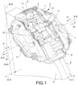
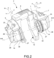
- a caliper body 1 for a brake caliper 2 for disc brake 3 is provided.
- an axial direction X-X is defined either coinciding with or parallel to the rotation axis A-A- of the disc 4 of the disc brake 3, a brake disc radial direction R-R orthogonal to the axial direction X-X, and a tangential direction T-T, orthogonal to both the axial direction X-X and to the brake disc radial direction R-R.
- the axial direction X-X defines an inner axial direction XI, directed towards the disc 4, and an outer axial direction XO, opposite with respect to said inner axial direction XI.
- Said caliper body 1 is adapted to straddle the disc 4.
- Said caliper body 1 comprises a first elongated portion 5 adapted to face, either directly or indirectly through the interposition of at least one brake pad 11, a first braking surface 6 of the disc 4, and a second elongated portion 7, opposite to said first elongated portion 5 and adapted to face, either directly or indirectly through the interposition of at least one brake pad 11, a second braking surface 8 of the disc 4 opposed to said first braking surface 6.
- Said caliper body 1 further comprises at least one caliper bridge 9 to connect said first elongated portion 5 and said second elongated portion 7 to each other arranged straddling the disc 4.
- At least either said elongated portion 5 or said second elongated portion 7 comprises at least one thrust device housing 10, or cylinder 10, adapted to receive at least one portion of a thrust device 13 or piston 13, adapted to apply a thrust action 14 directed in inner axial direction XI on at least one facing brake pad 11 to abut said at least one facing brake pad 11 against a braking surface 6, 8 of the disc 4.
- Said at least one thrust device housing 10 extends about a thrust axis a-a, parallel to the axial direction X-X, and defines a radial thrust direction r-r orthogonal to said thrust axis a-a and incident thereto.
- Said radial direction r-r defines an outer radial direction rI directed towards said thrust axis a-a and an outer radial direction rO, opposite to said inner radial direction rI.
- a circumferential direction of thrust device c-c, orthogonal to said thrust axis a-a, and said radial direction r-r, is also defined.
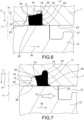
- At least either said elongated portion 5 and said second elongated portion 7 comprises a first annular housing 15 which radially opens into said thrust device housing 10.
- said first annular housing 15 is adapted to receive an elastic retraction element 30 or elastic roll-back element 30, adapted to apply a retracting action in outer axial direction XO on said thrust device 13.
- said first annular housing 15 is delimited at least partially in outer radial direction rO by a first bottom wall 16.
- said first annular housing 15 is delimited at least partially in inner axial direction XI by a second axial wall 17.
- said first annular housing 15 is delimited at least partially in outer axial direction XO by a third axial wall 18.
- At least either said first elongated portion 5 or said second elongated portion 7 further comprises a second annular housing 20 which radially opens into said first annular 15.
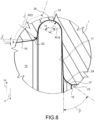
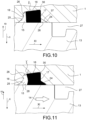
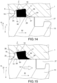
- said second annular chamber 20 is delimited in radial outer direction rO by a chamber bottom arched wall 19 having a chamber bottom arched wall concavity R19 facing in radial inner direction rI which joins in an axial inner portion thereof to said second axial wall 17 and in an axial outer portion thereof to said first bottom wall 16 of said first annular housing 15.
- said second annular chamber 20 is adapted to receive at least a portion of said elastic retraction element 30 at least when said thrust device 13 applies the thrust action 14.
- said chamber arched bottom wall 19 has a substantially constant radius of curvature.
- said first bottom wall 16 of the first annular housing 15 extends substantially along a straight line.
- said first bottom wall 16 of the first annular housing 15 is tapered in the outer axial direction XO, in other words away from the disc 4.
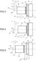
- said first bottom wall 16 of the first annular housing 15 tapers in outer axial direction XO, forming a first bottom wall angle ⁇ comprised between 6° and 8°, and preferably equal to 7°15'.
- the chamber bottom arched wall 19 sweeps an arched wall angle ⁇ between 170° and 220°.
- said arched wall angle ⁇ is comprised between 175° and 200°.
- said arched wall angle ⁇ is substantially equal to 180°.
- said arched wall angle ⁇ is evaluated on a plane parallel to the axial direction X-X and the radial thrust direction r-r.
- said chamber bottom arched wall 19 joins the first bottom wall 16 by means of a first connection 22 having first connection concavity R22 opposite with respect to said bottom wall chamber concavity R19.
- said concavity of first connection R22 is directed in outer radial direction rO.
- said first connection wall 22 sweeps a first connection wall angle ⁇ comprised between 96° and 98°, and preferably substantially equal to 97°15'.
- said second axial wall (17) extends substantially in thrust device radial direction r-r, preferably tapering in the outer radial direction rO by effect of the draft angles.
- said caliper body 1 is made of metal using foundry techniques, e.g. sand casting or shell casting. According to an embodiment, said caliper body 1 is made in one piece, e.g. with a single casting.
- said second axial wall 17 joins said chamber bottom arched wall 19 in a continuous manners, whereby not forming edges. According to an embodiment, said second axial wall 17 joins said chamber bottom arched wall 19 in thrust device radial direction r-r.
- said thrust device housing 10 is delimited at least partially in outer radial direction rO by at least one thrust device housing wall 23.
- said thrust device housing wall 23 joins to said second axial wall 17 by means of an inner axial stretch 24 parallel neither to the thrust device radial direction r-r nor to the axial direction X-X.
- said inner axial stretch 24 forms an inner axial stretch angle ⁇ comprised between 54° and 56° with said second inner axial wall 17.
- said inner axial stretch angle ⁇ is substantially equal to 55°.
- said inner axial stretch 24 forms an inner axial stretch angle ⁇ comprised between 54° and 56°, and preferably substantially equal to 55° with the thrust device radial direction r-r.
- said thrust device housing wall 23 joins to said third axial wall 18 by means of an inner axial stretch 25 parallel neither to the thrust device radial direction r-r nor to the axial direction X-X.
- said outer axial stretch 25 forms an angle comprised between 44° and 46°, and preferably substantially equal to 45° with the thrust device radial direction r-r.
- said thrust device housing 10 is delimited in outer axial direction XO by a housing back wall 29.
- said thrust device housing 10 is substantially cup-shaped.
- said third axial wall 18 joins to said first bottom wall 16 by means of a radial stretch 26 inclined and parallel neither to the radial direction r-r nor to the axial direction X-X.
- said radial stretch 26 forms an angle comprised between 44° and 46°, and preferably substantially equal to 45° with the thrust device radial direction r-r.
- said second axial wall 17 of the first annular housing 15 joins to said thrust device housing wall 23 by means of an inner axial stretch 24 which forms an inner axial stretch angle ⁇ with the thrust device radial direction r-r, to form an axially inner deformation chamber 37 for said elastic retraction element 30.
- said inner axial deformation chamber 37 has a wedge-shaped section of a tapering in inner axial direction XI.
- said inner axial stretch 24 comprises an arched stretch 36 having an inner arched axial stretch concavity R36 facing radial outer direction rO.
- said inner axial stretch angle ⁇ is comprised between 55° and 75°.
- said inner axial stretch angle ⁇ is substantially equal to 60°.
- said inner axial stretch angle ⁇ is substantially equal to 70°.
- said arched stretch 36 connects said inner axial stretch 24 with said second axial wall 17.
- the radius of curvature of said arched stretch 36 is comprised between 0.25 and 1.30.
- the radius of curvature of said arched stretch portion 36 is substantially equal to 0.30.
- the radius of curvature of said arched stretch portion 36 is substantially equal to 1.25.
- said first bottom wall 16 connects to said second axial wall 17 by means of an outer radial connection 38.
- said outer radial connection 38 has a radius of curvature comprised between 0.2 and 0.3, and preferably substantially equal to 0.25.
- a brake caliper 2 comprises a caliper body 1 according to any of the embodiments described above.
- said brake caliper 2 further comprises at least one pair of brake pads 11, each brake pad 11 comprising friction material 34, adapted to press against a facing braking surface 6 or 8 of the disc 4, and a support plate 33 which supports said friction material 34.
- said brake caliper 2 further comprises at least one thrust device 13 received in said at least one thrust device housing 10 so that it can slide axially with respect to said thrust device housing 10.
- the thrust axis a-a, parallel to the axial direction X-X, the radial thrust direction r-r orthogonal to said thrust axis a-a and incident to it, and the inner radial direction rI directed towards said thrust axis a-a, outer radial direction rO, opposite to said inner radial rI direction, and the circumferential direction of thrust device c-c, are understood to be also defined on said thrust device 13 when at least partially accommodated in said thrust device housing 10.
- said support plate 33 comprises a back plate 35 or pad back 35 facing opposite with respect to the friction material 34 and adapted to face such a thrust device 13.
- said thrust device 13 further comprises a thrust surface 32, adapted to abut against said back plate 35 of said brake pad 11, to apply the thrust action 14.
- At least said one thrust device 13 is in form of a piston having substantially cylindrical geometry which extends about the thrust axis a-a.
- At least one thrust device 13 comprises an outer wall or skirt 28 directed in axial direction X-X.
- said skirt 28 is also directed in the thrust device circumferential direction c-c.
- said skirt 28 of the thrust device 13 cooperates with said thrust housing wall 23 of the thrust device housing 10 to guide the movement in axial direction X-X of the thrust device 13 with respect to the caliper body 1. In this manner, said thrust action 14 is applied.
- said brake caliper 2 further comprises at least one elastic retraction element 30.
- said at least one elastic retraction element 30 has an annular shape and is received in said first annular housing 15.
- said at least one elastic retraction element 30 deforms elastically as a result of the inner axial direction XI applied by thrust device 13 towards the disc 4.
- the elastic retraction element 30 applies a retracting action on said thrust device 13, moving it away from the plate back 35 by an axial luft distance 31.
- said brake caliper 2 further comprises at least one axial spring 21 adapted to bias at least one brake pad 11 away from the disc when the retracting action ceases, in other words when the braking action ceases. In this manner, the axial spring 21 carries said plate back 35 against said thrust surface 32 of the thrust device 13.
- Fixing means of the vehicle 12, e.g. threaded, may be provided on said caliper body 1, e.g. on said second extended portion 7.
- the body of the retraction device 30, during the thrust action 14 deforms elastically in the inner axial direction XI in contact with the skirt 28 of the thrust device 13.
- the body of the retraction device 30, during the thrust action 14, deforms elastically occupying said second chamber 20, thus reducing its axial deformation in said chamber 37, which can, therefore, be made smaller the retracting action being equal, compared to known solutions.
- a disc brake 3 comprises at least one brake caliper 1 according to any one of the embodiments described above.
- said disc brake 3 comprises at least one disc brake disc 4.
Landscapes
- Engineering & Computer Science (AREA)
- General Engineering & Computer Science (AREA)
- Mechanical Engineering (AREA)
- Braking Arrangements (AREA)
Claims (10)
- Sattelkörper (1) für einen Bremssattel (2) für eine Bremsscheibe (3), wobei die Bremsscheibe (3) eine Axialrichtung (X - X) definiert, welche entweder koinzident mit oder parallel zu einer Rotationsachse (A - A) einer Scheibe (4) einer Bremsscheibe (3) ist; wobei die Axialrichtung (X - X) eine innere Axialrichtung (XI), welche zu der Scheibe (4) gerichtet ist, und eine äußere Axialrichtung (XO) definiert, welche entgegengesetzt mit Bezug zu der inneren Axialrichtung (XI) ist;wobei der Sattelkörper (1) dazu eingerichtet ist, die Scheibe (4) zu überspannen; und wobei der Sattelkörper (1) umfasst:- einen ersten verlängerten Abschnitt (5), welcher dazu eingerichtet ist, einer ersten Bremsfläche (6) der Scheibe (4) entweder direkt oder indirekt durch ein Einfügen wenigstens einer Bremsbacke (11) zugewandt zu sein;- einen zweiten verlängerten Abschnitt (7), entgegengesetzt zu dem ersten verlängerten Abschnitt (5) und welcher dazu eingerichtet ist, einer zweiten Bremsfläche (8) der Scheibe (4), welche entgegengesetzt der ersten Bremsfläche (6) ist, entweder direkt oder indirekt durch ein Einfügen wenigstens einer zweiten Bremsbacke (11) zugewandt zu sein;- wenigstens eine Sattelbrücke (9), um den ersten verlängerten Bereich (5) und den zweiten verlängerten Bereich (7) miteinander zu verbinden, welche für ein Überspannen der Scheibe (4) angeordnet ist;und wobei wenigstens entweder der erste verlängerte Abschnitt (5) oder der zweite verlängerte Abschnitt (7) umfasst:- wenigstens ein Schubvorrichtungsgehäuse (10) oder einen Zylinder (10), welcher dazu eingerichtet ist, wenigstens einen Abschnitt einer Schubvorrichtung (13) aufzunehmen, welche dazu eingerichtet ist, eine Schubbewegung (14), welche in die innere Axialrichtung (XI) gerichtet ist, auf wenigstens eine zugewandte Bremsbacke (11) anzuwenden, um die wenigstens eine zugewandte Bremsbacke (11) gegen eine Bremsfläche (6, 8) der Scheibe (4) anzulegen;- wobei das wenigstens eine Schubvorrichtungsgehäuse (10) sich entlang einer Schubachse (a - a) erstreckt, welche parallel zu der Axialrichtung (X - X) ist, und eine Radialrichtung (r - r) orthogonal zu der Schubachse (a - a) und inzident dazu definiert; wobei die Schubvorrichtung-Radialrichtung (r - r) eine innere Radialrichtung (rl), welche zu der Schubachse (a - a) gerichtet ist, und eine äußere Radialrichtung (rO) definiert, welche entgegengesetzt zu der inneren Radialrichtung (rl) ist;- ein erstes ringförmiges Gehäuse (15), welches sich radial in das Schubvorrichtungsgehäuse (10) öffnet, wobei das erste ringförmige Gehäuse (15) dazu eingerichtet ist, ein elastisches Rückstellungselement (30) aufzunehmen, welches dazu eingerichtet ist, eine Rückstellbewegung in einer äußeren Axialrichtung (XO) auf die Schubvorrichtung (13) anzuwenden; wobei das erste ringförmige Gehäuse (15) wenigstens teilweise in einer äußeren Radialrichtung (rO) durch eine untere Wand (16) und in einer inneren Axialrichtung (XI) durch eine zweite axiale Wand (17) begrenzt ist;- eine zweite ringförmige Kammer (20), welche sich radial in das erste ringförmige Gehäuse (15) öffnet, wobei die zweite ringförmige Kammer (20) in einer äußeren Radialrichtung (rO) durch eine untere gewölbte Kammerwand (19) begrenzt ist, welche eine untere gewölbte Kammerwandkonkavität (R19) aufweist, welche entgegengesetzt in einer inneren Radialrichtung (rl) ist, welche mit der zweiten axialen Wand (17) in einem inneren Axialabschnitt davon und in einem äußeren Axialabschnitt davon mit der ersten unteren Wand (16) des ersten ringförmigen Gehäuses (15) zusammenkommt, sodass die zweite ringförmige Kammer (20) dazu eingerichtet ist, wenigstens einen Abschnitt des elastischen Rückstellelements (30) aufzunehmen, wenigstens wenn die Schubvorrichtung (13) die Schubbewegung (14) anwendet,wobei die zweite axiale Wand (17) mit der unteren gewölbten Kammerwand (19) in einer kontinuierlichen Weise zusammenkommt, wobei keine Ränder gebildet sind.
- Sattelkörper (1) nach Anspruch 1, wobei:- die untere gewölbte Kammerwand (19) mit einem im Wesentlichen konstanten Kurvenradius gewölbt ist; oder wobei- sich die erste untere Wand (16) des ersten ringförmigen Gehäuses (15) im Wesentlichen entlang einer geraden Linie erstreckt; oder wobei- sich die erste untere Wand (16) des ersten ringförmigen Gehäuses (15) in der äußeren Axialrichtung (XO) verjüngt, welche vorzugsweise einen ersten unteren Wandwinkel (y) bildet, welcher zwischen 6° und 8° umfasst ist, und vorzugsweise gleich 7°15' ist; oder wobei- die erste untere Wand (16), eine untere gewölbte Kammerwand (19) und die zweite axiale Wand (17) gemeinsam aufeinanderfolgend sind und verbunden sind, um Ränder zwischen ihnen zu vermeiden.
- Sattelkörper (1) nach Anspruch 1 oder 2, wobei:- sich die untere gewölbte Kammerwand (19) in einem gewölbten Wandwinkel (α) herumführt, welcher zwischen 170° und 220° umfasst ist, und vorzugsweise zwischen 175° und 200° ist, und vorzugsweise im Wesentlichen gleich 180° ist; oder dass- der gewölbte Wandwinkel (α) an einer Ebene parallel zu der Axialrichtung (X - X) und der Radialrichtung (r - r) festgelegt ist; oder wobei- die untere gewölbte Kammerwand (19) mit der ersten unteren Wand (16) mit Hilfe einer ersten Verbindung (22) zusammenkommt, welche eine erste Verbindungskonkavität (R22) aufweist, welche mit Bezug auf die untere Kammerwandkonkavität (R19) entgegengesetzt ist; oder wobei- die erste Verbindungswand (22) einen Winkel überstreicht, welcher zwischen 96° und 98° umfasst ist, und vorzugsweise im Wesentlichen gleich 97°15' ist.
- Sattelkörper (1) nach einem der vorhergehenden Ansprüche, wobei:- sich die zweite axiale Wand (17) im Wesentlichen in einer Schubvorrichtung-Radialrichtung (r - r) erstreckt; oder wobei- die zweite axiale Wand (17) mit der untere gewölbte Kammerwand (19) im Wesentlichen in der Schubvorrichtung-Radialrichtung (r - r) zusammenkommt.
- Sattelkörper (1) nach einem der vorhergehenden Ansprüche, wobei:- das Schubvorrichtungsgehäuse (10) wenigstens teilweise in einer äußeren Radialrichtung (rO) durch wenigstens eine Schubvorrichtungsgehäusewand (23) begrenzt ist; oder wobei- die Schubvorrichtungsgehäusewand (23) mit der zweiten axialen Wand (17) mit Hilfe einer inneren axialen Streckung (24) zusammenkommt, welche weder parallel zu der Schubvorrichtung-Radialrichtung (r - r) noch zu der axialen Richtung (X - X) ist; oder wobei- die innere axiale Streckung (24) einen inneren axialen Streckungswinkel (β), welcher zwischen 54° und 56° umfasst ist, und vorzugsweise im Wesentlichen gleich 55° ist, mit der zweiten inneren axialen Wand (17) bildet; oder wobei- die innere axiale Streckung (24) einen inneren axialen Streckungswinkel (β), welcher zwischen 54° und 56° umfasst ist, und vorzugsweise im Wesentlichen gleich 55° ist, mit der Schubvorrichtung-Radialrichtung (r - r) bildet; oder wobei- die zweite axiale Wand (17) und die innere axiale Streckung (24) gemeinsam aufeinanderfolgend sind und verbunden sind, um Ränder zwischen ihnen zu vermeiden; oder wobei- die erste untere Wand (16), die untere gewölbte Kammerwand (19), die zweite axiale Wand (17) und die innere axiale Streckung (24) gemeinsam aufeinanderfolgend sind und verbunden sind, um Ränder zwischen ihnen zu vermeiden.
- Sattelkörper (1) nach einem der vorhergehenden Ansprüche, wobei:- die Schubvorrichtungsgehäusewand (23) mit einer dritten axialen Wand (18) zusammenkommt, welche das erste Radialgehäuse (15) in einer äußeren Axialrichtung (XO) mit Hilfe einer äußeren axialen Streckung (25) begrenzt, welche weder parallel zu der Schubvorrichtung-Radialrichtung (r - r) noch zu der axialen Richtung (X - X) ist; oder wobei- die äußere axiale Streckung (25) einen Winkel, welcher zwischen 44° und 46° umfasst ist, und vorzugsweise im Wesentlichen gleich 45° ist, mit der Schubvorrichtung-Radialrichtung (r - r) bildet.
- Bremssattel (2), umfassend einen Sattelkörper (1) nach einem der vorhergehenden Ansprüche.
- Bremssattel (2) nach Anspruch 7, ferner umfassend:- wenigstens eine Schubvorrichtung (13), welche in dem wenigstens einen Schubvorrichtungsgehäuse (10) aufgenommen ist, sodass sie axial mit Bezug auf das Schubvorrichtungsgehäuse (10) gleiten kann; oder- wenigstens ein elastisches Rückstellelement (30); oder wobei- das wenigstens eine elastische Rückstellelement (30) eine ringförmige Form aufweist und in dem ersten ringförmigen Gehäuse (15) aufgenommen ist; oder wobei- wenigstens eine Schubvorrichtung (13) in Form eines Kolbens ist, welcher im Wesentlichen eine zylindrische Geometrie aufweist, welche sich um die Schubachse (a - a) erstreckt; oder wobei- die wenigstens eine Schubvorrichtung (13) eine Schürze (28) umfasst, welche in Axialrichtung (X - X) gerichtet ist; oder wobei- die Schürze (28) der Schubvorrichtung (13) mit der Schubvorrichtungswand (23) des Schubvorrichtungsgehäuse (10) kooperiert, um die Bewegung in Axialrichtung (X - X) der Schubvorrichtung (13) mit Bezug auf den Sattelkörper (1) zu führen.
- Bremssattel (2) nach Anspruch 7 oder 8, ferner umfassend wenigstens ein Paar von Bremsbacken (11), wobei jede Bremsbacke (11) ein Reibungsmaterial (34), welches dazu eingerichtet ist, um gegen eine zugewandten Bremsfläche (6 oder 8) der Scheibe (4) zu drücken, und eine Unterstützungsplatte (33) umfasst, welche das Reibungsmaterial (34) unterstützt; oder wobei die Unterstützungsplatte (33) eine hintere Platte (35) umfasst, welche mit Bezug auf das Reibungsmaterial (34) entgegengesetzt zugewandt ist und dazu eingerichtet ist, einer solchen Schubvorrichtung (13) zugewandt zu sein; oder wobei- die Schubvorrichtung (13) ferner eine Schubfläche (32) umfasst, welche dazu eingerichtet ist, gegen die hintere Platte (35) der Bremsbacke (11) anzuliegen, um die Schubbewegung (14) anzuwenden; oder wobei- der Bremssattel (2) ferner wenigstens eine axiale Feder (21) umfasst, welche dazu eingerichtet ist, um wenigstens eine Bremsbacke (11) weg von der Scheibe (4) vorzuspannen.
- Bremsscheibe (3), umfassend wenigstens einen Bremssattel (2) nach einem der vorhergehenden Ansprüche.
Applications Claiming Priority (2)
| Application Number | Priority Date | Filing Date | Title |
|---|---|---|---|
| IT102019000006965A IT201900006965A1 (it) | 2019-05-17 | 2019-05-17 | Corpo pinza per una pinza freno |
| PCT/IB2020/054477 WO2020234693A1 (en) | 2019-05-17 | 2020-05-12 | Caliper body for a brake caliper |
Publications (2)
| Publication Number | Publication Date |
|---|---|
| EP3969775A1 EP3969775A1 (de) | 2022-03-23 |
| EP3969775B1 true EP3969775B1 (de) | 2024-12-04 |
Family
ID=67998557
Family Applications (1)
| Application Number | Title | Priority Date | Filing Date |
|---|---|---|---|
| EP20730726.5A Active EP3969775B1 (de) | 2019-05-17 | 2020-05-12 | Bremssattelkörper für einen bremssattel |
Country Status (5)
| Country | Link |
|---|---|
| US (1) | US12253132B2 (de) |
| EP (1) | EP3969775B1 (de) |
| CN (1) | CN113950587B (de) |
| IT (1) | IT201900006965A1 (de) |
| WO (1) | WO2020234693A1 (de) |
Families Citing this family (2)
| Publication number | Priority date | Publication date | Assignee | Title |
|---|---|---|---|---|
| CN114776737B (zh) * | 2022-03-29 | 2025-11-25 | 浙江万安智驭汽车控制系统有限公司 | 一种整体式固定卡钳及砂型 |
| DE102024000010A1 (de) * | 2024-01-02 | 2025-07-03 | Chr. Mayr Gmbh + Co. Kg | Elektromagnetische Federdruckbremse mit Freistellung |
Family Cites Families (13)
| Publication number | Priority date | Publication date | Assignee | Title |
|---|---|---|---|---|
| FR2186100A5 (de) * | 1972-05-22 | 1974-01-04 | Bendix Corp | |
| DE3241164C2 (de) * | 1982-11-08 | 1986-10-23 | Alfred Teves Gmbh, 6000 Frankfurt | Hydraulische Betätigungseinheit |
| JP3218258B2 (ja) * | 1993-02-22 | 2001-10-15 | トヨタ自動車株式会社 | ディスクブレーキ装置 |
| JPH06249274A (ja) | 1993-02-24 | 1994-09-06 | Aisin Takaoka Ltd | ベンチレーテッドディスク |
| JP3303563B2 (ja) * | 1994-03-11 | 2002-07-22 | トヨタ自動車株式会社 | ディスクブレーキ装置 |
| JPH10325432A (ja) | 1997-03-26 | 1998-12-08 | Sumitomo Electric Ind Ltd | ディスクブレーキ装置 |
| FR2798974B1 (fr) * | 1999-09-29 | 2001-12-14 | Peugeot Citroen Automobiles Sa | Etrier de frein a disque a recul piston ameliore |
| JP2005249190A (ja) * | 2004-02-05 | 2005-09-15 | Shimano Inc | 油圧ディスクブレーキ装置 |
| US20090272606A1 (en) * | 2008-05-02 | 2009-11-05 | Akebono Corporation (North America) | Triple chamfer seal groove |
| EP2370707B1 (de) | 2008-12-02 | 2014-05-28 | Freni Brembo S.p.A. | Rückstellvorrichtung für einen bremssattelkolben |
| ITMI20111693A1 (it) * | 2011-09-20 | 2013-03-21 | Freni Brembo Spa | Corpo pinza per freno a disco |
| US8794369B1 (en) | 2012-11-08 | 2014-08-05 | Ride-Able, Inc. | Motorcycle brake assist system |
| WO2015155708A1 (en) * | 2014-04-08 | 2015-10-15 | Freni Brembo S.P.A. | Disc brake pad, spring for disc brake caliper and disk brake caliper assembly |
-
2019
- 2019-05-17 IT IT102019000006965A patent/IT201900006965A1/it unknown
-
2020
- 2020-05-12 WO PCT/IB2020/054477 patent/WO2020234693A1/en not_active Ceased
- 2020-05-12 EP EP20730726.5A patent/EP3969775B1/de active Active
- 2020-05-12 CN CN202080043541.6A patent/CN113950587B/zh active Active
- 2020-05-12 US US17/595,391 patent/US12253132B2/en active Active
Also Published As
| Publication number | Publication date |
|---|---|
| CN113950587B (zh) | 2025-03-28 |
| US20220213942A1 (en) | 2022-07-07 |
| EP3969775A1 (de) | 2022-03-23 |
| US12253132B2 (en) | 2025-03-18 |
| IT201900006965A1 (it) | 2020-11-17 |
| CN113950587A (zh) | 2022-01-18 |
| WO2020234693A1 (en) | 2020-11-26 |
Similar Documents
| Publication | Publication Date | Title |
|---|---|---|
| US3688876A (en) | Disc brake of the floating type | |
| US11773932B2 (en) | Pad return spring for a disc brake caliper body | |
| EP2370707B1 (de) | Rückstellvorrichtung für einen bremssattelkolben | |
| US6247561B1 (en) | Disk brake | |
| EP3969775B1 (de) | Bremssattelkörper für einen bremssattel | |
| US4055238A (en) | Anti-squeal device in disc brake | |
| JPH0668298B2 (ja) | デイスクブレーキ | |
| EP3436715B1 (de) | Scheibenbremssattelkörper | |
| CN113906232A (zh) | 盘式制动器的制动卡钳、盘式制动系统及检测装置 | |
| US4993519A (en) | Brake with two discs of fixed spacing | |
| US9181998B2 (en) | Disc brake device and caliper slide mechanism | |
| US5613577A (en) | Automotive disc brake with improved caliper assembly | |
| US20040200676A1 (en) | Electric sliding disc brake system | |
| EP1752673A1 (de) | Scheibenbremse | |
| EP3652459B1 (de) | Bremssattel und mindestens eine belaganordnung | |
| EP3899305B1 (de) | Sattelkörper und bremssattel mit einem solchen sattelkörper | |
| US6695099B1 (en) | Twin piston single bore brake caliper apparatus | |
| US4072214A (en) | Disc brake with non-deformable yoke | |
| CN108953431B (zh) | 制动器辅助复位机构 | |
| JPS60157523A (ja) | デイスクブレーキ | |
| JP4969520B2 (ja) | キャリパブレーキ装置 | |
| WO2008079087A1 (en) | Method and device for disc brakes and vehicle | |
| US20110278110A1 (en) | Sealed Floating Shim for A Brake Caliper | |
| CN115435030A (zh) | 浮动卡钳 | |
| IT201900006966A1 (it) | Corpo pinza per una pinza freno |
Legal Events
| Date | Code | Title | Description |
|---|---|---|---|
| STAA | Information on the status of an ep patent application or granted ep patent |
Free format text: STATUS: UNKNOWN |
|
| STAA | Information on the status of an ep patent application or granted ep patent |
Free format text: STATUS: THE INTERNATIONAL PUBLICATION HAS BEEN MADE |
|
| PUAI | Public reference made under article 153(3) epc to a published international application that has entered the european phase |
Free format text: ORIGINAL CODE: 0009012 |
|
| STAA | Information on the status of an ep patent application or granted ep patent |
Free format text: STATUS: REQUEST FOR EXAMINATION WAS MADE |
|
| 17P | Request for examination filed |
Effective date: 20211115 |
|
| AK | Designated contracting states |
Kind code of ref document: A1 Designated state(s): AL AT BE BG CH CY CZ DE DK EE ES FI FR GB GR HR HU IE IS IT LI LT LU LV MC MK MT NL NO PL PT RO RS SE SI SK SM TR |
|
| DAV | Request for validation of the european patent (deleted) | ||
| DAX | Request for extension of the european patent (deleted) | ||
| STAA | Information on the status of an ep patent application or granted ep patent |
Free format text: STATUS: EXAMINATION IS IN PROGRESS |
|
| 17Q | First examination report despatched |
Effective date: 20230524 |
|
| P01 | Opt-out of the competence of the unified patent court (upc) registered |
Effective date: 20230526 |
|
| TPAC | Observations filed by third parties |
Free format text: ORIGINAL CODE: EPIDOSNTIPA |
|
| GRAP | Despatch of communication of intention to grant a patent |
Free format text: ORIGINAL CODE: EPIDOSNIGR1 |
|
| STAA | Information on the status of an ep patent application or granted ep patent |
Free format text: STATUS: GRANT OF PATENT IS INTENDED |
|
| INTG | Intention to grant announced |
Effective date: 20240712 |
|
| GRAS | Grant fee paid |
Free format text: ORIGINAL CODE: EPIDOSNIGR3 |
|
| GRAA | (expected) grant |
Free format text: ORIGINAL CODE: 0009210 |
|
| STAA | Information on the status of an ep patent application or granted ep patent |
Free format text: STATUS: THE PATENT HAS BEEN GRANTED |
|
| AK | Designated contracting states |
Kind code of ref document: B1 Designated state(s): AL AT BE BG CH CY CZ DE DK EE ES FI FR GB GR HR HU IE IS IT LI LT LU LV MC MK MT NL NO PL PT RO RS SE SI SK SM TR |
|
| REG | Reference to a national code |
Ref country code: CH Ref legal event code: EP |
|
| REG | Reference to a national code |
Ref country code: DE Ref legal event code: R096 Ref document number: 602020042473 Country of ref document: DE |
|
| REG | Reference to a national code |
Ref country code: IE Ref legal event code: FG4D |
|
| REG | Reference to a national code |
Ref country code: LT Ref legal event code: MG9D |
|
| REG | Reference to a national code |
Ref country code: NL Ref legal event code: MP Effective date: 20241204 |
|
| PG25 | Lapsed in a contracting state [announced via postgrant information from national office to epo] |
Ref country code: HR Free format text: LAPSE BECAUSE OF FAILURE TO SUBMIT A TRANSLATION OF THE DESCRIPTION OR TO PAY THE FEE WITHIN THE PRESCRIBED TIME-LIMIT Effective date: 20241204 |
|
| PG25 | Lapsed in a contracting state [announced via postgrant information from national office to epo] |
Ref country code: FI Free format text: LAPSE BECAUSE OF FAILURE TO SUBMIT A TRANSLATION OF THE DESCRIPTION OR TO PAY THE FEE WITHIN THE PRESCRIBED TIME-LIMIT Effective date: 20241204 |
|
| PG25 | Lapsed in a contracting state [announced via postgrant information from national office to epo] |
Ref country code: BG Free format text: LAPSE BECAUSE OF FAILURE TO SUBMIT A TRANSLATION OF THE DESCRIPTION OR TO PAY THE FEE WITHIN THE PRESCRIBED TIME-LIMIT Effective date: 20241204 |
|
| PG25 | Lapsed in a contracting state [announced via postgrant information from national office to epo] |
Ref country code: ES Free format text: LAPSE BECAUSE OF FAILURE TO SUBMIT A TRANSLATION OF THE DESCRIPTION OR TO PAY THE FEE WITHIN THE PRESCRIBED TIME-LIMIT Effective date: 20241204 |
|
| PG25 | Lapsed in a contracting state [announced via postgrant information from national office to epo] |
Ref country code: NO Free format text: LAPSE BECAUSE OF FAILURE TO SUBMIT A TRANSLATION OF THE DESCRIPTION OR TO PAY THE FEE WITHIN THE PRESCRIBED TIME-LIMIT Effective date: 20250304 |
|
| PG25 | Lapsed in a contracting state [announced via postgrant information from national office to epo] |
Ref country code: LV Free format text: LAPSE BECAUSE OF FAILURE TO SUBMIT A TRANSLATION OF THE DESCRIPTION OR TO PAY THE FEE WITHIN THE PRESCRIBED TIME-LIMIT Effective date: 20241204 Ref country code: GR Free format text: LAPSE BECAUSE OF FAILURE TO SUBMIT A TRANSLATION OF THE DESCRIPTION OR TO PAY THE FEE WITHIN THE PRESCRIBED TIME-LIMIT Effective date: 20250305 |
|
| PG25 | Lapsed in a contracting state [announced via postgrant information from national office to epo] |
Ref country code: RS Free format text: LAPSE BECAUSE OF FAILURE TO SUBMIT A TRANSLATION OF THE DESCRIPTION OR TO PAY THE FEE WITHIN THE PRESCRIBED TIME-LIMIT Effective date: 20250304 |
|
| PG25 | Lapsed in a contracting state [announced via postgrant information from national office to epo] |
Ref country code: NL Free format text: LAPSE BECAUSE OF FAILURE TO SUBMIT A TRANSLATION OF THE DESCRIPTION OR TO PAY THE FEE WITHIN THE PRESCRIBED TIME-LIMIT Effective date: 20241204 |
|
| REG | Reference to a national code |
Ref country code: AT Ref legal event code: MK05 Ref document number: 1748471 Country of ref document: AT Kind code of ref document: T Effective date: 20241204 |
|
| PG25 | Lapsed in a contracting state [announced via postgrant information from national office to epo] |
Ref country code: SM Free format text: LAPSE BECAUSE OF FAILURE TO SUBMIT A TRANSLATION OF THE DESCRIPTION OR TO PAY THE FEE WITHIN THE PRESCRIBED TIME-LIMIT Effective date: 20241204 |
|
| PG25 | Lapsed in a contracting state [announced via postgrant information from national office to epo] |
Ref country code: PL Free format text: LAPSE BECAUSE OF FAILURE TO SUBMIT A TRANSLATION OF THE DESCRIPTION OR TO PAY THE FEE WITHIN THE PRESCRIBED TIME-LIMIT Effective date: 20241204 |
|
| PG25 | Lapsed in a contracting state [announced via postgrant information from national office to epo] |
Ref country code: IS Free format text: LAPSE BECAUSE OF FAILURE TO SUBMIT A TRANSLATION OF THE DESCRIPTION OR TO PAY THE FEE WITHIN THE PRESCRIBED TIME-LIMIT Effective date: 20250404 |
|
| PG25 | Lapsed in a contracting state [announced via postgrant information from national office to epo] |
Ref country code: PT Free format text: LAPSE BECAUSE OF FAILURE TO SUBMIT A TRANSLATION OF THE DESCRIPTION OR TO PAY THE FEE WITHIN THE PRESCRIBED TIME-LIMIT Effective date: 20250404 |
|
| PG25 | Lapsed in a contracting state [announced via postgrant information from national office to epo] |
Ref country code: EE Free format text: LAPSE BECAUSE OF FAILURE TO SUBMIT A TRANSLATION OF THE DESCRIPTION OR TO PAY THE FEE WITHIN THE PRESCRIBED TIME-LIMIT Effective date: 20241204 |
|
| PG25 | Lapsed in a contracting state [announced via postgrant information from national office to epo] |
Ref country code: AT Free format text: LAPSE BECAUSE OF FAILURE TO SUBMIT A TRANSLATION OF THE DESCRIPTION OR TO PAY THE FEE WITHIN THE PRESCRIBED TIME-LIMIT Effective date: 20241204 Ref country code: RO Free format text: LAPSE BECAUSE OF FAILURE TO SUBMIT A TRANSLATION OF THE DESCRIPTION OR TO PAY THE FEE WITHIN THE PRESCRIBED TIME-LIMIT Effective date: 20241204 |
|
| PG25 | Lapsed in a contracting state [announced via postgrant information from national office to epo] |
Ref country code: SK Free format text: LAPSE BECAUSE OF FAILURE TO SUBMIT A TRANSLATION OF THE DESCRIPTION OR TO PAY THE FEE WITHIN THE PRESCRIBED TIME-LIMIT Effective date: 20241204 |
|
| PG25 | Lapsed in a contracting state [announced via postgrant information from national office to epo] |
Ref country code: CZ Free format text: LAPSE BECAUSE OF FAILURE TO SUBMIT A TRANSLATION OF THE DESCRIPTION OR TO PAY THE FEE WITHIN THE PRESCRIBED TIME-LIMIT Effective date: 20241204 |
|
| PG25 | Lapsed in a contracting state [announced via postgrant information from national office to epo] |
Ref country code: IT Free format text: LAPSE BECAUSE OF FAILURE TO SUBMIT A TRANSLATION OF THE DESCRIPTION OR TO PAY THE FEE WITHIN THE PRESCRIBED TIME-LIMIT Effective date: 20241204 |
|
| REG | Reference to a national code |
Ref country code: DE Ref legal event code: R097 Ref document number: 602020042473 Country of ref document: DE |
|
| PG25 | Lapsed in a contracting state [announced via postgrant information from national office to epo] |
Ref country code: SE Free format text: LAPSE BECAUSE OF FAILURE TO SUBMIT A TRANSLATION OF THE DESCRIPTION OR TO PAY THE FEE WITHIN THE PRESCRIBED TIME-LIMIT Effective date: 20241204 |
|
| PG25 | Lapsed in a contracting state [announced via postgrant information from national office to epo] |
Ref country code: DK Free format text: LAPSE BECAUSE OF FAILURE TO SUBMIT A TRANSLATION OF THE DESCRIPTION OR TO PAY THE FEE WITHIN THE PRESCRIBED TIME-LIMIT Effective date: 20241204 |
|
| PLBE | No opposition filed within time limit |
Free format text: ORIGINAL CODE: 0009261 |
|
| STAA | Information on the status of an ep patent application or granted ep patent |
Free format text: STATUS: NO OPPOSITION FILED WITHIN TIME LIMIT |
|
| REG | Reference to a national code |
Ref country code: CH Ref legal event code: L10 Free format text: ST27 STATUS EVENT CODE: U-0-0-L10-L00 (AS PROVIDED BY THE NATIONAL OFFICE) Effective date: 20251015 |
|
| 26N | No opposition filed |
Effective date: 20250905 |
|
| REG | Reference to a national code |
Ref country code: DE Ref legal event code: R119 Ref document number: 602020042473 Country of ref document: DE |
|
| REG | Reference to a national code |
Ref country code: CH Ref legal event code: H13 Free format text: ST27 STATUS EVENT CODE: U-0-0-H10-H13 (AS PROVIDED BY THE NATIONAL OFFICE) Effective date: 20251223 |
|
| PG25 | Lapsed in a contracting state [announced via postgrant information from national office to epo] |
Ref country code: LU Free format text: LAPSE BECAUSE OF NON-PAYMENT OF DUE FEES Effective date: 20250512 |
|
| PG25 | Lapsed in a contracting state [announced via postgrant information from national office to epo] |
Ref country code: CH Free format text: LAPSE BECAUSE OF NON-PAYMENT OF DUE FEES Effective date: 20250531 |
|
| GBPC | Gb: european patent ceased through non-payment of renewal fee |
Effective date: 20250512 |
|
| REG | Reference to a national code |
Ref country code: BE Ref legal event code: MM Effective date: 20250531 |
|
| PG25 | Lapsed in a contracting state [announced via postgrant information from national office to epo] |
Ref country code: MC Free format text: LAPSE BECAUSE OF FAILURE TO SUBMIT A TRANSLATION OF THE DESCRIPTION OR TO PAY THE FEE WITHIN THE PRESCRIBED TIME-LIMIT Effective date: 20241204 |
|
| PG25 | Lapsed in a contracting state [announced via postgrant information from national office to epo] |
Ref country code: GB Free format text: LAPSE BECAUSE OF NON-PAYMENT OF DUE FEES Effective date: 20250512 |
|
| PG25 | Lapsed in a contracting state [announced via postgrant information from national office to epo] |
Ref country code: IE Free format text: LAPSE BECAUSE OF NON-PAYMENT OF DUE FEES Effective date: 20250512 Ref country code: DE Free format text: LAPSE BECAUSE OF NON-PAYMENT OF DUE FEES Effective date: 20251202 |
|
| PG25 | Lapsed in a contracting state [announced via postgrant information from national office to epo] |
Ref country code: BE Free format text: LAPSE BECAUSE OF NON-PAYMENT OF DUE FEES Effective date: 20250531 |
|
| PG25 | Lapsed in a contracting state [announced via postgrant information from national office to epo] |
Ref country code: FR Free format text: LAPSE BECAUSE OF NON-PAYMENT OF DUE FEES Effective date: 20250531 |