EP3969735B1 - Motor mit einem zündeinsatz mit aktiver vorkammer - Google Patents
Motor mit einem zündeinsatz mit aktiver vorkammer Download PDFInfo
- Publication number
- EP3969735B1 EP3969735B1 EP20737511.4A EP20737511A EP3969735B1 EP 3969735 B1 EP3969735 B1 EP 3969735B1 EP 20737511 A EP20737511 A EP 20737511A EP 3969735 B1 EP3969735 B1 EP 3969735B1
- Authority
- EP
- European Patent Office
- Prior art keywords
- insert
- injector
- well
- chamber
- gas ejection
- Prior art date
- Legal status (The legal status is an assumption and is not a legal conclusion. Google has not performed a legal analysis and makes no representation as to the accuracy of the status listed.)
- Active
Links
Images


Classifications
-
- F—MECHANICAL ENGINEERING; LIGHTING; HEATING; WEAPONS; BLASTING
- F02—COMBUSTION ENGINES; HOT-GAS OR COMBUSTION-PRODUCT ENGINE PLANTS
- F02B—INTERNAL-COMBUSTION PISTON ENGINES; COMBUSTION ENGINES IN GENERAL
- F02B19/00—Engines characterised by precombustion chambers
- F02B19/02—Engines characterised by precombustion chambers the chamber being periodically isolated from its cylinder
-
- F—MECHANICAL ENGINEERING; LIGHTING; HEATING; WEAPONS; BLASTING
- F02—COMBUSTION ENGINES; HOT-GAS OR COMBUSTION-PRODUCT ENGINE PLANTS
- F02B—INTERNAL-COMBUSTION PISTON ENGINES; COMBUSTION ENGINES IN GENERAL
- F02B19/00—Engines characterised by precombustion chambers
- F02B19/06—Engines characterised by precombustion chambers with auxiliary piston in chamber for transferring ignited charge to cylinder space
-
- F—MECHANICAL ENGINEERING; LIGHTING; HEATING; WEAPONS; BLASTING
- F02—COMBUSTION ENGINES; HOT-GAS OR COMBUSTION-PRODUCT ENGINE PLANTS
- F02B—INTERNAL-COMBUSTION PISTON ENGINES; COMBUSTION ENGINES IN GENERAL
- F02B19/00—Engines characterised by precombustion chambers
- F02B19/10—Engines characterised by precombustion chambers with fuel introduced partly into pre-combustion chamber, and partly into cylinder
- F02B19/1019—Engines characterised by precombustion chambers with fuel introduced partly into pre-combustion chamber, and partly into cylinder with only one pre-combustion chamber
- F02B19/108—Engines characterised by precombustion chambers with fuel introduced partly into pre-combustion chamber, and partly into cylinder with only one pre-combustion chamber with fuel injection at least into pre-combustion chamber, i.e. injector mounted directly in the pre-combustion chamber
-
- F—MECHANICAL ENGINEERING; LIGHTING; HEATING; WEAPONS; BLASTING
- F02—COMBUSTION ENGINES; HOT-GAS OR COMBUSTION-PRODUCT ENGINE PLANTS
- F02B—INTERNAL-COMBUSTION PISTON ENGINES; COMBUSTION ENGINES IN GENERAL
- F02B19/00—Engines characterised by precombustion chambers
- F02B19/12—Engines characterised by precombustion chambers with positive ignition
-
- F—MECHANICAL ENGINEERING; LIGHTING; HEATING; WEAPONS; BLASTING
- F02—COMBUSTION ENGINES; HOT-GAS OR COMBUSTION-PRODUCT ENGINE PLANTS
- F02B—INTERNAL-COMBUSTION PISTON ENGINES; COMBUSTION ENGINES IN GENERAL
- F02B19/00—Engines characterised by precombustion chambers
- F02B19/16—Chamber shapes or constructions not specific to sub-groups F02B19/02 - F02B19/10
- F02B19/18—Transfer passages between chamber and cylinder
-
- F—MECHANICAL ENGINEERING; LIGHTING; HEATING; WEAPONS; BLASTING
- F02—COMBUSTION ENGINES; HOT-GAS OR COMBUSTION-PRODUCT ENGINE PLANTS
- F02D—CONTROLLING COMBUSTION ENGINES
- F02D37/00—Non-electrical conjoint control of two or more functions of engines, not otherwise provided for
- F02D37/02—Non-electrical conjoint control of two or more functions of engines, not otherwise provided for one of the functions being ignition
-
- F—MECHANICAL ENGINEERING; LIGHTING; HEATING; WEAPONS; BLASTING
- F02—COMBUSTION ENGINES; HOT-GAS OR COMBUSTION-PRODUCT ENGINE PLANTS
- F02M—SUPPLYING COMBUSTION ENGINES IN GENERAL WITH COMBUSTIBLE MIXTURES OR CONSTITUENTS THEREOF
- F02M57/00—Fuel-injectors combined or associated with other devices
- F02M57/06—Fuel-injectors combined or associated with other devices the devices being sparking plugs
-
- F—MECHANICAL ENGINEERING; LIGHTING; HEATING; WEAPONS; BLASTING
- F02—COMBUSTION ENGINES; HOT-GAS OR COMBUSTION-PRODUCT ENGINE PLANTS
- F02P—IGNITION, OTHER THAN COMPRESSION IGNITION, FOR INTERNAL-COMBUSTION ENGINES; TESTING OF IGNITION TIMING IN COMPRESSION-IGNITION ENGINES
- F02P13/00—Sparking plugs structurally combined with other parts of internal-combustion engines
-
- F—MECHANICAL ENGINEERING; LIGHTING; HEATING; WEAPONS; BLASTING
- F02—COMBUSTION ENGINES; HOT-GAS OR COMBUSTION-PRODUCT ENGINE PLANTS
- F02P—IGNITION, OTHER THAN COMPRESSION IGNITION, FOR INTERNAL-COMBUSTION ENGINES; TESTING OF IGNITION TIMING IN COMPRESSION-IGNITION ENGINES
- F02P15/00—Electric spark ignition having characteristics not provided for in, or of interest apart from, groups F02P1/00 - F02P13/00 and combined with layout of ignition circuits
- F02P15/006—Ignition installations combined with other systems, e.g. fuel injection
-
- Y—GENERAL TAGGING OF NEW TECHNOLOGICAL DEVELOPMENTS; GENERAL TAGGING OF CROSS-SECTIONAL TECHNOLOGIES SPANNING OVER SEVERAL SECTIONS OF THE IPC; TECHNICAL SUBJECTS COVERED BY FORMER USPC CROSS-REFERENCE ART COLLECTIONS [XRACs] AND DIGESTS
- Y02—TECHNOLOGIES OR APPLICATIONS FOR MITIGATION OR ADAPTATION AGAINST CLIMATE CHANGE
- Y02T—CLIMATE CHANGE MITIGATION TECHNOLOGIES RELATED TO TRANSPORTATION
- Y02T10/00—Road transport of goods or passengers
- Y02T10/10—Internal combustion engine [ICE] based vehicles
- Y02T10/12—Improving ICE efficiencies
Definitions
- the present invention relates to an active pre-chamber ignition insert which makes it possible to house an active pre-chamber in a small and minimally intrusive manner in the cylinder head of an internal combustion engine.
- active pre-chambers there are many concepts of active pre-chambers, the latter being used as an ignition means to ignite a main charge contained in the combustion chamber of an internal combustion engine.
- active pre-chamber is usually used to refer to pre-chambers into which, in addition to an electric spark plug known per se, at least one fuel injector, whether or not associated with an air injector, or at least one air and fuel mixture injector, opens.
- These two applications belong to the applicant and have the particularity of separating the pre-chamber from the main chamber by means of a valve or a shuttle electrode.
- This innovative configuration offers numerous possibilities compared to conventional pre-chambers which communicate permanently with the combustion chamber of the engine.
- patent applications No. FR 3 061 743 and No. FR 3 060 222 have been the subject of an application for improvement patent No. 18 58111 dated 10 September 2018 This latter request belongs to the applicant and concerns the magnetic recall of the valve or the shuttle electrode.
- all pre-chamber ignition devices provide that a pilot charge primarily composed of air and fuel is first introduced into said pre-chamber. Then, said pilot charge is ignited by a spark plug. As it burns, the pilot charge sees its pressure increased to the point that it is ejected at high temperature and high speed in the form of torches of burning gas into the three-dimensional space of the engine's combustion chamber. By passing through the volume of said chamber, said torches ignite the main charge it contains.
- the combination of powerful ignition and highly diluted charges allows the pre-ignition chambers by troche to significantly reduce the fuel consumption of spark-ignition internal combustion engines, in particular by limiting pumping losses and heat losses at the walls.
- the main charge being highly diluted and its combustion being rapid, said charge is also not very sensitive to knocking which makes it possible to provide for the engine which receives it a high volumetric ratio and an optimal ignition advance, these two particularities making it possible to confer a high efficiency to the thermodynamic cycle implemented.
- One of the difficulties in implementing active ignition pre-chambers is the space occupied by the spark plug and the injector that the said pre-chambers receive, and which open into the very small volume of the said pre-chambers.
- This arrangement results in a substantial radial bulk of the assembly consisting of the pre-chamber, the spark plug and the injector.
- said arrangement makes it difficult to produce pre-chambers of very small volume without the internal surface/volume ratio of said pre-chambers being very large and excessively promotes the cooling of the pilot charge gases once the latter have been brought to a high temperature.
- the significant bulk of the various components of the active pre-chamber reduces the space available for housing the water chambers which cool the cylinder head, the intake and exhaust ducts of the internal combustion engine, and the camshafts of said engine.
- cooling the pre-chamber becomes potentially difficult to ensure if it is not in direct contact with the cooling water circulating in the water chambers of the cylinder head.
- the active pre-chamber ignition insert according to the invention makes it possible to meet an unmet need to be able to efficiently and inexpensively install an active pre-chamber on any type of reciprocating internal combustion engine.
- the active pre-chamber ignition insert according to the invention is intended to be inexpensive to manufacture in large series, in order to remain compatible with the economic constraints of most of the applications for which it is intended, including automobiles.
- the active pre-chamber ignition insert according to the invention can be applied to any rotary or reciprocating internal combustion engine, whatever the type, whatever the gaseous, liquid or solid fuel it consumes, and whether its main charge is diluted with cooled or uncooled EGR, with a neutral gas of any nature whatsoever, or with a gas rich in oxygen or any other oxidant.
- pilot charge intended to ignite the main charge of any spark-ignition engine which receives the active pre-chamber ignition insert according to the invention may contain a fuel and/or an oxidant different from the fuel and/or oxidant which constitutes said main charge.
- the internal combustion engine according to the present invention comprises a pre-chamber nose which consists of an added nose which covers the gas ejection duct, the gas ejection orifice being arranged in said added nose.
- the internal combustion engine according to the present invention comprises a space forming an insert cooling water chamber which is left between the cylindrical insert body and the insert well.
- the internal combustion engine according to the present invention comprises a lateral injector well which is made up of an openwork or non-continuous bore which communicates along its length with at least one cylinder head cooling water chamber which the cylinder head comprises.
- the internal combustion engine according to the present invention comprises an insert clamping ferrule which bears on the ferrule clamping face by means of a retention spring.
- the internal combustion engine comprises clamping means which consist of at least one insert clamping ferrule having an external ferrule thread cooperating with the insert well fixing means which consist of an internal well thread, said ferrule being pierced in its center to allow the spark plug to pass through.
- the internal combustion engine according to the present invention comprises an insert bearing surface which directly or indirectly forms a ball joint with the insert bearing shoulder while the cylindrical insert body directly or indirectly forms a ball joint with the clamping means.
- the internal combustion engine according to the present invention comprises clamping means which bear on the cylindrical insert body by means of a sliding-swivel washer which can move radially either relative to the cylindrical insert body or relative to the clamping means.
- the internal combustion engine according to the present invention comprises a sliding-swivel washer which is flexible and which forms a restraining spring.
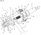
- the internal combustion engine according to the present invention comprises an injector nose which is held pressed in the radial injector orifice and against the cylindrical insert body by elastic clamping means which bear on the one hand on the injector, and on the other hand on the cylinder head.
- the internal combustion engine according to the present invention comprises elastic clamping means which consist of a flange which bears on the injector on the one hand, and which is connected to the cylinder head by at least one flange screw on the other hand.
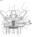
- the active pre-chamber ignition insert 1 is particularly intended for an internal combustion engine 2, the latter comprising a cylinder head 3 which covers a cylinder 4 to form, with a piston 31, a combustion chamber 5 into which a main charge 30 can be introduced.
- the cylinder head 3 houses an ignition pre-chamber 71 into which a spark plug 12 and an injector nose 16 of at least one injector 8 open and into which a pilot charge 9 can be introduced, said pre-chamber 71 being able to communicate with the combustion chamber 5 successively via a gas ejection duct 76 and via at least one gas ejection orifice 24 which opens into said chamber 5 via a pre-chamber nose 75.
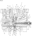
- the active pre-chamber ignition insert 1 comprises at least one insert well 72 arranged in the cylinder head 3.
- Said insert well 72 comprises fixing means which consist of an internal well thread 82 over part of its length.
- said well 72 opens on the one hand, outside the cylinder head 3 via a large diameter insert introduction orifice 78, and on the other hand, into the combustion chamber 5 via a smaller diameter pre-chamber nose orifice 77, the two said diameters being connected to each other by at least one insert support shoulder 79 which may for example be flat or conical.
- the ignition insert with active pre-chamber 1 has at least one cylindrical insert body 70 made up of one or more parts and in which are in particular arranged the ignition pre-chamber 71 and the gas ejection duct 76.
- the cylindrical insert body 70 is housed with little play in the insert well 72, is indexed in rotation relative to the cylinder head 3, and ends with the pre-chamber nose 75 which passes through the pre-chamber nose orifice 77.
- the cylindrical insert body 70 also has an insert bearing surface 80 which rests directly or indirectly on the insert bearing shoulder 79.
- a support seal 25 may be provided between the insert support surface 80 and the insert support shoulder 79 which provides a seal between the insert well 72 and the combustion chamber 5.
- Said seal 25 may be metallic such as annealed copper or be of any other type known to those skilled in the art.
- the active pre-chamber ignition insert 1 has at least one insert spark plug well 83 arranged in the cylindrical insert body 70, parallel to the axis of said body 70 or forming a closed angle relative to said axis and at the center or close to the center of said body 70, said spark plug well 83 opening on the one hand, at the end of the cylindrical insert body 70 which is axially opposite the pre-chamber nose 75, and on the other hand, into the ignition pre-chamber 71.
- the insert spark plug well 83 receives the spark plug 12 or the injector nose 16.
- the active pre-chamber ignition insert 1 comprises at least one radial injector orifice 88 arranged radially in the cylindrical insert body 70 but not necessarily perpendicular to the latter and in which the end of the injector nose 16 or the spark plug 12 is housed.
- Said orifice 88 connects the ignition pre-chamber 71 and/or the gas ejection duct 76 with the external surface of the cylindrical insert body 70 while a seal can be provided between the radial injector orifice 88 and the injector nose 16 which takes the form of a segment, a seal or any other means known to those skilled in the art, and which prevents any leakage of liquid or gas between the pre-chamber ignition 71 and/or the gas ejection duct 76 and the external surface of the cylindrical insert body 70.
- the radial injector orifice 88 and the injector nose 16 can constitute a ball joint allowing a small angular movement between said orifice 88 and said nose 16.
- the active pre-chamber ignition insert 1 comprises at least one lateral injector well 73 arranged in the cylinder head 3 in one or more parts depending on the arrangement of the constituent material of the cylinder head 3 crossed.
- Said well 73 receives the body of the injector nose 16 and, as the case may be, all or part of the other components of the injector 8, or the spark plug 12. Said well 73 connects the exterior of the cylinder head 3 - that is to say, for example, the intake ducts of the internal combustion engine 2 - with the insert well 72.
- the radial injector orifice 88 is aligned with the lateral injector well 73 so that the end of the injector nose 16 or of the spark plug 12 opens into the ignition pre-chamber 71 and/or the gas ejection duct 76 by successively passing through the lateral injector well 73 and the radial injector orifice 88.
- cylindrical insert body 70 is deemed to be correctly indexed in rotation relative to the cylinder head 3 when the injector nose 16 is simultaneously housed in the lateral injector well 73 and in the radial injector orifice 88.
- a seal may advantageously be provided between the lateral injector well 73 and the injector nose 16, said seal taking the form of a segment, a seal or any other means known to those skilled in the art, and said seal isolating all or part of the interior of the lateral injector well 73 from the exterior of the cylinder head 3.
- the lateral injector well 73 on the one hand, and the body of the injector nose 16 or any other constituent part of the injector 8 on the other hand, can constitute a ball joint allowing a small angular movement between said lateral well 73 and said injector 8.
- the injector side well 73 can be housed in the casting of the cylinder head 3 at the level of the intake ports of the internal combustion engine 2. This location is slightly disruptive to the flow of gases but advantageous in terms of architecture.
- the inlet of the injector side well 73 can be provided deep enough in the cylinder head so that only the body of the injector nose 16 passes through the intake ports.
- the active pre-chamber ignition insert 1 comprises clamping means which consist of at least one insert clamping ferrule 74 which has an external ferrule thread 81 which cooperates with the internal well thread 82.
- the insert clamping ferrule 74 bears directly or indirectly on a ferrule clamping face 84 presented to it by the cylindrical insert body 70 in order to directly or indirectly maintain the insert bearing surface 80 of said body 70 pressed against the insert bearing shoulder 79.
- the insert clamping ferrule 74 is drilled in its center to allow the spark plug 12 to pass through.
- the insert clamping ferrule 74 can advantageously provide a key grip allowing it to be rotated for the purpose of tightening it, said key grip being able to consist of notches, orifices, or a female or male shape of any geometry whatsoever complementary to a shape that a tightening key has.
- the pre-chamber nose 75 can accommodate a stratification valve 13 which is pressed either against the end of the gas ejection duct 76 to close the latter in a sealed manner, or against a valve surface on the chamber side 21 to form with the gas ejection duct 76 a torch ignition pre-chamber 23 which communicates simultaneously on the one hand, with the ignition pre-chamber 71 via the gas ejection duct 76, and on the other hand, with the combustion chamber 5 via the gas ejection orifice 24.
- a stratification valve 13 which is pressed either against the end of the gas ejection duct 76 to close the latter in a sealed manner, or against a valve surface on the chamber side 21 to form with the gas ejection duct 76 a torch ignition pre-chamber 23 which communicates simultaneously on the one hand, with the ignition pre-chamber 71 via the gas ejection duct 76, and on the other hand, with the combustion chamber 5 via the gas ejection orifice 24.
- a magnetic field source 44 can be positioned on the cylindrical insert body 70 to produce a magnetic field which tends to keep the stratification valve 13 pressed against the end of the gas ejection conduit 76 as disclosed in patent application No. 18 58111 dated September 10, 2018 belonging to the applicant.
- the cylindrical insert body 70 is advantageously made in whole or in part of a magnetic material 43.
- the magnetic field source 44 may take the form of a permanent magnet 53 which may not be fixed by any mechanical means on the cylindrical insert body 70 and may only remain in position on the latter due to its magnetic bonding.
- the magnetic field source 44 may consist of a coil of conductive wire which produces a magnetic field when said wire is crossed by an electric current.
- This particular configuration makes it possible, for example, not to recall the stratification valve 13 pressed against the end of the gas ejection duct 76 during cold starting of the internal combustion engine 2, which makes it possible to supply the ignition pre-chamber 71 with fuel mixture not by means of the injector 8, but directly through the gas ejection orifices 24 via the gas ejection duct 76, said mixture coming from the combustion chamber 5.
- the gas ejection conduit 76 may be made of a magnetic material 43 and form at the level of its contact with the stratification valve 13 a gas ejection tube 89 whose external diameter is less than that of said valve 13, said tube 89 being enclosed in a non-magnetic sleeve 85 made of a non-magnetic material 50.
- the non-magnetic sleeve 85 prevents the stratification valve 13 from becoming crooked in its housing by forcing the magnetic flux produced by the magnetic field source 44 to generate field lines which are non-parallel to the stratification valve 13 at the periphery of the latter.
- non-magnetic sleeve 85 can be mainly made of copper which has a high thermal conductivity, and be mounted tightly by shrink fitting around the gas ejection tube 89 to ensure maximum thermal cohesion between itself and said tube 89.
- the stratification valve 13 can be flat to form with the end of the gas ejection duct a flat sealed contact which avoids locating said valve 13 radially unlike a conical seat.
- Said flat contact also has the advantage of leaving a maximum section for the passage of gases at the same valve lift 13 when the latter is open 76, that is to say when it rests on the valve surface on the chamber side 21 with which it cooperates.
- the periphery of the stratification valve 13 can advantageously be truncated and not cylindrical, which makes it possible to prevent any jamming of said valve in its housing, whatever its orientation relative to the gas ejection tube 89 with which it cooperates.
- the stratification flap 13 can be flat on both sides so that its manufacture is simplified.
- the pre-chamber nose 75 may consist of an added nose 90 which covers the gas ejection duct 76, the gas ejection orifice 24 being arranged in said added nose 90.
- the added nose 90 allows, if necessary, the introduction of a stratification valve 13 into the pre-chamber nose 75 as provided for in patent application No. FR 3 061 743 .
- valve 13 is recalled by a magnetic field source 44 as described in patent application No. 18 58111 , it is possible to choose for the 90 nose piece a non-magnetic material 50 such as copper which also has high thermal conductivity.
- the added nose 90 can be mounted tightly by shrinking around the gas ejection tube 89 to ensure maximum thermal cohesion between itself and said tube 89, or around said tube 89 already enclosed in a non-magnetic sleeve 85 as shown in the figures 1 , 2 , 4 And 5 .
- the inserted nose 90 may have a support collar 91 which is held tight between the insert support surface 80 and the insert support shoulder 79 when the cylindrical insert body 70 is correctly placed in the insert well 72.
- a space forming an insert cooling water chamber 86 may be left between the cylindrical insert body 70 and the insert well 72, cooling water coming for example from the cylinder head 3 being able to circulate in said water chamber 86.
- At least one well seal 26 may be provided placed between the cylindrical insert body 70 and the insert well 72 which prevents cooling water from escaping outside the cylinder head 3 while at least one other seal prevents said water from entering the combustion chamber 5.
- the lateral injector well 73 may consist of an openwork or non-continuous bore which communicates along its length with at least one cylinder head cooling water chamber 41 which the cylinder head 3 comprises. This particular configuration allows the insert well 72 to communicate with said water chamber 41.
- the body of the injector nose 16 is immersed for part of its length in the cooling water contained in said water chamber 41.
- the diameter of the lateral injector well 73 can advantageously be provided to be significantly larger than that of the injector nose 16 which it houses so that the cooling water can pass freely around said nose 16 to enter the insert well 72 or to exit the latter.
- the lateral injector well 73 can pass right through the insert well 72 to allow cooling water to circulate between said well 72 and at least two cylinder head cooling water chambers 41 that the cylinder head 3 comprises.
- the insert clamping ferrule 74 can bear on the ferrule clamping face 84 by means of a restraining spring 87, the latter guaranteeing on the one hand, an approximately constant force for maintaining the insert bearing surface 80 on the insert bearing shoulder 79 and on the other hand, a good seal between said surface 80 and said shoulder 79, in all circumstances.
- the retention spring 87 can take the form of at least one “Belleville” washer known per se, or at least one corrugated spring washer.
- the restraining spring 87 can allow the internal thread of the well 82 and the external thread of the ferrule 81 to be replaced by a simple groove provided in the insert well 72 and in which a stop ring is housed, said ring bearing on the one hand in said groove and on the other hand, on the insert clamping ferrule 74.
- This particular configuration of the active pre-chamber ignition insert 1 according to the invention allows the cylindrical insert body 70 to freely orient itself relative to the cylinder head 2.
- the insert bearing surface 80 may for example be truncated in relief while the insert bearing shoulder 79 may be conical in hollow.
- FIG. 5 also illustrates that the clamping means 74 can bear on the cylindrical insert body 70 by means of a sliding-swivel washer 92 which can move radially either relative to the cylindrical insert body 70 or relative to the clamping means 74.
- the sliding-swivel washer 92 can expose on the one hand, to the cylindrical insert body 70 a flat contact face, and on the other hand, to the clamping means 74 a hollow conical housing which cooperates with a raised truncated spherical shape presented by said means 74, said conical housing and said truncated spherical shape forming a ball joint.
- the sliding-swivel washer 92 can be flexible and form a restraining spring 87 which prevents the loosening of the clamping means 74 and guarantees the force of pressing the insert bearing surface 80 onto the insert bearing shoulder 79 regardless of the thermal expansion differences between the cylindrical insert body 70 and the insert well 72 which houses it.
- the pre-chamber nose 75 may comprise a pre-chamber nose seal 93 made for example of elastomer material, said seal 93 providing a seal between the combustion chamber 5 and the insert cooling water chamber 86, said seal 93 being able to be protected from flames and hot gases present in the combustion chamber 5 by a pre-chamber nose fire segment 94.
- the end of the injector nose 16 can advantageously be frusto-spherical and rest in a conical bearing surface made in the cylindrical insert body 70, at the level of the radial injector orifice 88.
- the elastic clamping means 95 may consist of a flange 96 which bears on the injector 8 on the one hand, and which is connected to the cylinder head 3 by at least one flange screw 97 on the other hand.
- flange springs 98 can advantageously be interposed between the flange 96 and the head of the flange screws 97, said springs 98 being able to be “Belleville” washers known per se, be helical springs, or be of any type known to those skilled in the art.
- the cylindrical insert body 70 of the active pre-chamber ignition insert 1 is mounted in the insert well 72, the latter having been provided in place of the spark plug well of the cylinder head of a conventional spark ignition engine.
- an insert well 72 has been produced, the diameter of which at the level of the cylindrical insert body 70 is twenty-four millimeters. It will be noted that this assembly can also be provided in place of the injector well of a conventional Diesel engine.
- the spark plug is deliberately compact. It can, for example, be an "Iridium” type spark plug Performance IY24" from the company "Denso" which has an eight millimeter diameter thread and a thirteen millimeter hex key socket.
- the active pre-chamber ignition insert 1 receives a stratification valve 13 kept pressed at rest against the end of the gas ejection duct 76 by a magnetic field produced by a magnetic field source 44.
- the cylindrical insert body 70 received a non-magnetic sleeve 85 which was shrink-fitted by temperature difference onto the gas ejection tube 89, then the assembly was topped with an added nose 90 also mounted by shrink-fitting, the stratification valve 13 having been previously introduced into said nose 90.
- the cylindrical insert body 70 was introduced into the insert well 72 shown in the figures 1 , 2 And 5 until its insert bearing surface 80 comes into contact with the insert bearing shoulder 79 via the bearing seal 25 and, according to this non-limiting example embodiment, via a bearing collar 91 presented by the added nose 90. Then, said body 70 was rotated along its longitudinal axis until the radial injector orifice 88 that it presents is aligned with the lateral injector well 73 arranged in the cylinder head 3.
- the injector nose 16 was introduced into the lateral injector well 73 until said nose 16 opened into the ignition pre-chamber 71 at the desired depth.
- the lateral injector well 73 is oriented perpendicular to the axis of the cylindrical insert body 70. This orientation is given here only as an example. Indeed, the lateral injector well 73 and the radial injector orifice 88 with which it cooperates can be freely oriented relative to the axis of the cylindrical insert body 70 so that said well 73 does not interfere or interferes as little as possible with the essential components of the cylinder head 3, and does not disturb or disturb as little as possible the operation of said components.
- the restraining spring 87 was placed in the insert well 72 followed by the insert clamping ferrule 74, the latter having been screwed to a predetermined torque to ensure the desired contact pressure between the insert bearing surface 80 and the insert bearing shoulder 79, via the bearing seal 25 and the bearing collar 91.
- the insert cooling water chamber 86 formed by the space left between the cylindrical insert body 70 and the insert well 72. Said chamber 86 makes it possible - according to a particular embodiment of the active pre-chamber ignition insert 1 according to the invention - to cool the cylindrical insert body 70.
- the insert cooling water chamber 86 also cools the gas ejection duct 76, the gas ejection tube 89, the non-magnetic sleeve 85, and the insert nose 90.
- the non-magnetic sleeve 85 and the insert nose 90 can advantageously be made of alloyed copper, this material offering high thermal conductivity.
- the heat is efficiently exported from the pre-chamber nose 75 in which the gas ejection orifices 24 are arranged to the insert cooling water chamber 86.
Landscapes
- Engineering & Computer Science (AREA)
- Chemical & Material Sciences (AREA)
- Combustion & Propulsion (AREA)
- Mechanical Engineering (AREA)
- General Engineering & Computer Science (AREA)
- Combustion Methods Of Internal-Combustion Engines (AREA)
- Cylinder Crankcases Of Internal Combustion Engines (AREA)
- Ignition Installations For Internal Combustion Engines (AREA)
Claims (11)
- Verbrennungsmotor (2) mit einem Zylinderkopf (3), der einen Zylinder (4) so überdeckt, dass er mit einem Kolben (31) einen Brennraum (5) bildet, in den eine Hauptladung (30) eingebracht werden kann, wobei der Zylinderkopf (3) eine Zündvorkammer (71) einschließt, in die eine Zündkerze (12) und eine Einspritznase (16) mindestens eines Einspritzventils (8) münden und in die eine Zündladung (9) eingebracht werden kann, wobei die Vorkammer (71) nacheinander über einen Gasausstoßkanal (76) und über mindestens eine Gasausstoßöffnung (24), die über eine Vorkammernase (75) in den Brennraum (5) mündet, mit dem Brennraum (5) in Verbindung steht, umfassend einen Zündeinsatz mit aktiver Vorkammer (1), der umfasst:• Mindestens einen Einsatzschacht (72), der im Zylinderkopf (3) ausgebildet ist und Befestigungsmittel (82) aufweist, wobei der Schacht (72) einerseits über eine Einsatzeinführöffnung (78) mit großem Durchmesser nach außerhalb des Zylinderkopfs (3) führt und andererseits über eine Vorkammernasenöffnung (77) mit kleinerem Durchmesser in den Brennraum (5) mündet, wobei die beiden Durchmesser durch mindestens eine Einsatzauflageschulter (79) miteinander verbunden sind;• Mindestens einen zylindrischen Einsatzkörper (70), der aus einem oder mehreren Teilen besteht und in dem unter anderem die Zündvorkammer (71) und der Gasausstoßkanal (76) ausgebildet sind, wobei der Körper (70) mit geringem Spiel im Einsatzschacht (72) untergebracht ist, in Bezug auf den Zylinderkopf (3) in Drehung indexiert ist, und mit der Vorkammernase (75) endet, die die Vorkammernasenöffnung (77) durchquert, während der Körper (70) eine Einsatzauflagefläche (80) aufweist, die direkt oder indirekt auf der Einsatzauflageschulter (79) aufliegt;• Mindestens einen Einsatzzündkerzenschacht (83), der in dem zylindrischen Einsatzkörper (70) parallel zur Achse des Körpers (70) oder in einem spitzen Winkel zu dieser Achse und in der Mitte oder nahe der Mitte des Körpers (70) angeordnet ist, wobei der Zündkerzenschacht (83) einerseits an das Ende des zylindrischen Einsatzkörpers (70)führt, das der Vorkammernase (75) axial gegenüberliegt, und andererseits in die Zündvorkammer (71) mündet, wobei der Zündkerzenschacht (83) die Zündkerze (12) oder die Einspritznase (16) aufnimmt;• Mindestens eine radial im zylindrischen Einsatzkörper (70) angeordnete, aber nicht zwangsläufig senkrecht zu diesem verlaufende radiale Einspritzöffnung (88), in der das Ende der Einspritznase (16) oder der Zündkerze (12) untergebracht ist, wobei die Öffnung (88) die Zündvorkammer (71) und/oder den Gasausstoßkanal (76) mit der Außenfläche des zylindrischen Einsatzkörpers (70) verbindet;• Mindestens einen seitlichen Einspritzschacht (73), der im Zylinderkopf (3) ausgebildet ist, wobei der Schacht (73) den Körper der Einspritznase (16) oder die Zündkerze (12) aufnimmt und die Außenseite des Zylinderkopfs (3) mit dem Einsatzschacht (72) verbindet, während die radiale Einspritzöffnung (88) so auf den Schacht (73) ausgerichtet ist, dass das Ende der Einspritznase (16) oder der Zündkerze (12) in die Zündvorkammer (71) und/oder den Gasausstoßkanal (76) mündet, indem es nacheinander den seitlichen Einspritzschacht (73) und die radiale Einspritzöffnung (88) durchquert;• Spannmittel (74), die mit den Befestigungsmitteln (82) zusammenwirken, um die Einsatzauflagefläche (80) des zylindrischen Einsatzkörpers (70) direkt oder indirekt an der Einsatzauflageschulter (79) anliegend zu halten;• dadurch gekennzeichnet, dass die Vorkammernase (75) ein Schichtungsventil (13) einschließt, das entweder gegen das Ende des Gasausstoßkanals (76) gedrückt wird, um diesen dicht zu verschließen, oder gegen eine kammerseitige Ventilfläche (21), um mit dem Gasausstoßkanal (76) eine Zündbrenner-Vorkammer (23) zu bilden, die gleichzeitig einerseits mit der Zündvorkammer (71) über den Gasausstoßkanal (76) und andererseits mit dem Brennraum (5) über die Gasausstoßöffnung (24) in Verbindung steht;• und dass er außerdem mindestens eine Magnetfeldquelle (44) umfasst, die auf dem zylindrischen Einsatzkörper (70) positioniert ist, wobei die Quelle ein Magnetfeld erzeugt, das darauf abzielt, das Schichtungsventil (13) gegen das Ende des Gasausstoßkanals (76) gedrückt zu halten, wobei letzteres aus einem magnetischen Material (43) besteht und im Bereich seines Kontakts mit dem Schichtungsventil (13) ein Gasausstoßrohr (89) bildet, dessen Außendurchmesser kleiner ist als der des Ventils (13), wobei das Rohr (89) in einer nichtmagnetischen Hülse (85) aus einem nichtmagnetischen Material (50) eingeschlossen ist.
- Verbrennungsmotor (2) nach Anspruch 1, dadurch gekennzeichnet, dass die Vorkammernase (75) aus einer aufgesetzten Nase (90) besteht, die den Gasausstoßkanal (76) überdeckt, wobei die Gasausstoßöffnung (24) in der aufgesetzten Nase (90) ausgebildet ist.
- Verbrennungsmotor (2) nach Anspruch 1, dadurch gekennzeichnet, dass zwischen dem zylindrischen Einsatzkörper (70) und dem Einsatzschacht (72) Platz für eine Einsatzkühlwasserkammer (86) gelassen wird.
- Verbrennungsmotor (2) nach Anspruch 1, dadurch gekennzeichnet, dass der seitliche Einspritzschacht (73) aus einer durchbrochenen oder nicht durchgehenden Bohrung besteht, die über ihre Länge mit mindestens einer Zylinderkopf-Kühlwasserkammer (41) in Verbindung steht, die der Zylinderkopf (3) umfasst.
- Verbrennungsmotor (2) nach Anspruch 1, dadurch gekennzeichnet, dass die Spannmittel aus mindestens einem Einsatzspannring (74) bestehen, der ein mit den Befestigungsmitteln des Einsatzschachts (72) zusammenwirkendes Außengewinde (81) aufweist, wobei die Befestigungsmittel des Einsatzschachts aus einem Innengewinde (82) bestehen, wobei der Ring (74) in seiner Mitte zum Durchführen der Zündkerze (12) durchbohrt ist.
- Verbrennungsmotor (2) nach Anspruch 5, dadurch gekennzeichnet, dass der Einsatzspannring (74) über eine Haltefeder (87) auf einer Spannring-Spannfläche (84) aufliegt.
- Verbrennungsmotor (2) nach Anspruch 1, dadurch gekennzeichnet, dass die Einsatzauflagefläche (80) direkt oder indirekt eine Kugelgelenkverbindung mit der Einsatzauflageschulter (79) bildet, während der zylindrische Einsatzkörper (70) direkt oder indirekt eine Kugelgelenkverbindung mit den Spannmitteln (74) bildet.
- Verbrennungsmotor (2) nach Anspruch 7, dadurch gekennzeichnet, dass die Spannmittel (74) über eine Gleit-Gelenk-Scheibe (92) auf dem zylindrischen Einsatzkörper (70) aufliegen, die sich entweder in Bezug auf den zylindrischen Einsatzkörper (70) oder in Bezug auf die Spannmittel (74) radial bewegen kann.
- Verbrennungsmotor (2) nach Anspruch 8, dadurch gekennzeichnet, dass die Gleit-Gelenk-Scheibe (92) elastisch ist und eine Haltefeder (87) bildet.
- Verbrennungsmotor (2) nach Anspruch 1, dadurch gekennzeichnet, dass die Einspritznase (16) in der radialen Einspritzöffnung (88) und gegen den zylindrischen Einsatzkörper (70) durch elastische Spannmittel (95) gedrückt gehalten wird, die einerseits am Einspritzventil (8) und andererseits am Zylinderkopf (3) anliegen.
- Verbrennungsmotor (2) nach Anspruch 10, dadurch gekennzeichnet, dass die elastischen Spannmittel (95) aus einem Flansch (96) bestehen, der einerseits an dem Einspritzventil (8) anliegt und andererseits über mindestens eine Flanschschraube (97) mit dem Zylinderkopf (3) verbunden ist.
Applications Claiming Priority (2)
| Application Number | Priority Date | Filing Date | Title |
|---|---|---|---|
| FR1904961A FR3096079B1 (fr) | 2019-05-13 | 2019-05-13 | Insert d’allumage a prechambre active |
| PCT/FR2020/050790 WO2020229775A1 (fr) | 2019-05-13 | 2020-05-13 | Insert d'allumage a prechambre active |
Publications (2)
| Publication Number | Publication Date |
|---|---|
| EP3969735A1 EP3969735A1 (de) | 2022-03-23 |
| EP3969735B1 true EP3969735B1 (de) | 2025-04-23 |
Family
ID=68210904
Family Applications (1)
| Application Number | Title | Priority Date | Filing Date |
|---|---|---|---|
| EP20737511.4A Active EP3969735B1 (de) | 2019-05-13 | 2020-05-13 | Motor mit einem zündeinsatz mit aktiver vorkammer |
Country Status (9)
| Country | Link |
|---|---|
| EP (1) | EP3969735B1 (de) |
| JP (1) | JP7590988B2 (de) |
| KR (1) | KR102876084B1 (de) |
| CN (1) | CN113795655B (de) |
| AU (1) | AU2020276402B2 (de) |
| CA (1) | CA3139564A1 (de) |
| ES (1) | ES3037761T3 (de) |
| FR (2) | FR3096079B1 (de) |
| WO (1) | WO2020229775A1 (de) |
Families Citing this family (7)
| Publication number | Priority date | Publication date | Assignee | Title |
|---|---|---|---|---|
| US11867114B2 (en) | 2020-10-16 | 2024-01-09 | Vianney Rabhi | Guide stud valve |
| FR3115323B1 (fr) * | 2020-10-16 | 2023-05-12 | Vianney Rabhi | clapet à téton de guidage |
| FR3145016A1 (fr) * | 2023-01-16 | 2024-07-19 | Vianney Rabhi | INSERT DE FRICTION POUR CLAPET orienté |
| EP4424981B1 (de) | 2023-03-03 | 2025-05-07 | Volvo Truck Corporation | Verfahren zum betreiben einer verbrennungskraftmaschinenanlage unter verwendung von wasserstoff-kraftstoff |
| DE102023106127A1 (de) * | 2023-03-13 | 2024-09-19 | Innio Jenbacher Gmbh & Co Og | Aufnahmebauteil für ein Vorkammerbauteil eines Verbrennungsmotors |
| CN116464547A (zh) * | 2023-04-18 | 2023-07-21 | 北京新能源汽车股份有限公司 | 分体式预燃室、发动机和车辆 |
| US20250075654A1 (en) * | 2023-08-31 | 2025-03-06 | Brp-Rotax Gmbh & Co. Kg | Internal combustion engine with combustion pre-chamber |
Family Cites Families (17)
| Publication number | Priority date | Publication date | Assignee | Title |
|---|---|---|---|---|
| DE2510176B1 (de) * | 1975-03-08 | 1976-08-26 | Daimler Benz Ag | Viertakt-hubkolben-brennkraftmaschine mit zuendkammer |
| US4074664A (en) * | 1976-02-12 | 1978-02-21 | Astron Innovations, Inc. | Fuel control system for internal combustion engines |
| US5611307A (en) * | 1991-10-14 | 1997-03-18 | The University Of Melbourne | Internal combustion engine ignition device |
| JP4288762B2 (ja) * | 1999-06-23 | 2009-07-01 | マツダ株式会社 | 筒内噴射式エンジンの吸気系構造 |
| DE10016558A1 (de) * | 2000-04-03 | 2001-10-11 | Dieter Kuhnert | Vorkammer-Zündkerze mit Zusatzkraftstoff zur Entflammung sehr magerer Kraftstoff-Luft-Gemische, insbesondere für Gasmotoren |
| US6513483B2 (en) * | 2001-02-07 | 2003-02-04 | Cooper Cameron Corporation | Pre-combustion chamber for an internal combustion engine |
| JP2006322367A (ja) | 2005-05-18 | 2006-11-30 | Nissan Motor Co Ltd | 副室式内燃機関 |
| EP1887215A1 (de) * | 2006-08-01 | 2008-02-13 | Siemens Aktiengesellschaft | Spannvorrichtung und Zylinderkopfanordnung |
| JP2009236017A (ja) * | 2008-03-27 | 2009-10-15 | Komatsu Ltd | 副室式ガスエンジン |
| DE102009049755A1 (de) * | 2009-10-17 | 2011-04-21 | Bayerische Motoren Werke Aktiengesellschaft | Verfahren zum Betreiben einer Kolbenbrennkraftmaschine sowie Kolbenbrennkraftmaschine |
| CN106194395A (zh) | 2014-09-25 | 2016-12-07 | 马勒动力总成有限公司 | 火花点火发动机的湍流射流点火预燃室燃烧系统 |
| US20160053668A1 (en) * | 2015-11-02 | 2016-02-25 | Caterpillar Inc. | Prechamber assembly for engine |
| US20160069250A1 (en) * | 2015-11-13 | 2016-03-10 | Caterpillar Inc. | Control valve for pre-combustion chamber assembly |
| US20160252007A1 (en) * | 2016-05-09 | 2016-09-01 | Caterpillar Inc. | Pre-chamber assembly for engine |
| US10041402B2 (en) * | 2016-05-12 | 2018-08-07 | Pratt & Whitney Canada Corp. | Internal combustion engine with split pilot injection |
| FR3060222B1 (fr) | 2016-12-09 | 2019-05-17 | Vianney Rabhi | Bougie d'allumage a electrode-navette |
| FR3061743B1 (fr) | 2017-01-12 | 2019-08-16 | Vianney Rabhi | Prechambre d'allumage a clapet |
-
2019
- 2019-05-13 FR FR1904961A patent/FR3096079B1/fr active Active
- 2019-11-29 FR FR1913531A patent/FR3096078B1/fr active Active
-
2020
- 2020-05-13 JP JP2021567056A patent/JP7590988B2/ja active Active
- 2020-05-13 CA CA3139564A patent/CA3139564A1/fr active Pending
- 2020-05-13 AU AU2020276402A patent/AU2020276402B2/en active Active
- 2020-05-13 CN CN202080033844.XA patent/CN113795655B/zh active Active
- 2020-05-13 KR KR1020217036773A patent/KR102876084B1/ko active Active
- 2020-05-13 ES ES20737511T patent/ES3037761T3/es active Active
- 2020-05-13 WO PCT/FR2020/050790 patent/WO2020229775A1/fr not_active Ceased
- 2020-05-13 EP EP20737511.4A patent/EP3969735B1/de active Active
Also Published As
| Publication number | Publication date |
|---|---|
| AU2020276402B2 (en) | 2025-07-24 |
| CN113795655B (zh) | 2024-02-20 |
| EP3969735A1 (de) | 2022-03-23 |
| AU2020276402A1 (en) | 2021-12-09 |
| ES3037761T3 (en) | 2025-10-06 |
| WO2020229775A1 (fr) | 2020-11-19 |
| KR102876084B1 (ko) | 2025-10-23 |
| JP7590988B2 (ja) | 2024-11-27 |
| CA3139564A1 (fr) | 2020-11-19 |
| KR20220006534A (ko) | 2022-01-17 |
| FR3096078B1 (fr) | 2023-06-09 |
| AU2020276402A9 (en) | 2025-05-22 |
| FR3096079B1 (fr) | 2022-11-18 |
| CN113795655A (zh) | 2021-12-14 |
| JP2022533068A (ja) | 2022-07-21 |
| FR3096079A1 (fr) | 2020-11-20 |
| FR3096078A1 (fr) | 2020-11-20 |
Similar Documents
| Publication | Publication Date | Title |
|---|---|---|
| EP3969735B1 (de) | Motor mit einem zündeinsatz mit aktiver vorkammer | |
| US11187141B2 (en) | Ignition insert with an active pre-chamber | |
| EP3850201B1 (de) | Magnetische ventilrückstellvorrichtung | |
| CA2649998C (fr) | Agencement d'une bougie du type a semi-conducteur dans une chambre de combustion de moteur a turbine a gaz | |
| EP4229284B1 (de) | Zündvorkammer mit ventil mit führungsstift | |
| FR2763639A1 (fr) | Moteur a combustion interne a injection de carburant avec chambre de sous-combustion | |
| FR2955618A1 (fr) | Culasse de moteur a combustion interne comportant un circuit de refroidissement | |
| EP3189939B1 (de) | Perfektionierungen für ein gasfixierungswerkzeug | |
| FR3145016A1 (fr) | INSERT DE FRICTION POUR CLAPET orienté | |
| FR2803335A1 (fr) | Dispositif d'injection d'un carburant a l'interieur d'une chambre de combustion d'un cylindre d'un moteur a combustion interne | |
| FR2862347A1 (fr) | Culasse de moteur a combustion interne et bougie d'allumage | |
| FR3115073A1 (fr) | Bougie d’allumage pour moteur à allumage commandé. | |
| FR2814288A1 (fr) | Dispositif d'allumage pour moteur a combustion interne | |
| WO2024008737A1 (fr) | Pompe à carburant pour l'injection directe de carburant pour les moteurs à combustion interne | |
| CA2894922C (fr) | Ensemble de prechauffage, culasse, moteur a pistons et aeronef | |
| FR3162475A1 (fr) | Préchambre d’allumage à clapet orienté | |
| WO2025242483A1 (fr) | Préchambre d'allumage à clapet orienté | |
| FR2906576A1 (fr) | Agencement de refroidissement d'un injecteur comportant un empilement de rondelles. | |
| EP4277051A1 (de) | Zündkerze für einen ottomotor | |
| FR3106619A1 (fr) | Pré-chambre multi-sites | |
| CH175765A (fr) | Moteur à combustion interne du type à injection de combustible liquide. | |
| FR3052526A1 (fr) | Vanne de controle d'un debit de fluide | |
| BE415672A (de) | ||
| FR2648515A1 (fr) | Procede de combustion d'un melange carburant-air dans un cylindre d'un moteur a combustion interne et systeme pour la mise en oeuvre de ce procede | |
| BE504781A (de) |
Legal Events
| Date | Code | Title | Description |
|---|---|---|---|
| STAA | Information on the status of an ep patent application or granted ep patent |
Free format text: STATUS: UNKNOWN |
|
| STAA | Information on the status of an ep patent application or granted ep patent |
Free format text: STATUS: THE INTERNATIONAL PUBLICATION HAS BEEN MADE |
|
| PUAI | Public reference made under article 153(3) epc to a published international application that has entered the european phase |
Free format text: ORIGINAL CODE: 0009012 |
|
| STAA | Information on the status of an ep patent application or granted ep patent |
Free format text: STATUS: REQUEST FOR EXAMINATION WAS MADE |
|
| 17P | Request for examination filed |
Effective date: 20211115 |
|
| AK | Designated contracting states |
Kind code of ref document: A1 Designated state(s): AL AT BE BG CH CY CZ DE DK EE ES FI FR GB GR HR HU IE IS IT LI LT LU LV MC MK MT NL NO PL PT RO RS SE SI SK SM TR |
|
| DAV | Request for validation of the european patent (deleted) | ||
| DAX | Request for extension of the european patent (deleted) | ||
| STAA | Information on the status of an ep patent application or granted ep patent |
Free format text: STATUS: EXAMINATION IS IN PROGRESS |
|
| 17Q | First examination report despatched |
Effective date: 20231206 |
|
| GRAP | Despatch of communication of intention to grant a patent |
Free format text: ORIGINAL CODE: EPIDOSNIGR1 |
|
| STAA | Information on the status of an ep patent application or granted ep patent |
Free format text: STATUS: GRANT OF PATENT IS INTENDED |
|
| INTG | Intention to grant announced |
Effective date: 20241121 |
|
| GRAS | Grant fee paid |
Free format text: ORIGINAL CODE: EPIDOSNIGR3 |
|
| GRAA | (expected) grant |
Free format text: ORIGINAL CODE: 0009210 |
|
| STAA | Information on the status of an ep patent application or granted ep patent |
Free format text: STATUS: THE PATENT HAS BEEN GRANTED |
|
| AK | Designated contracting states |
Kind code of ref document: B1 Designated state(s): AL AT BE BG CH CY CZ DE DK EE ES FI FR GB GR HR HU IE IS IT LI LT LU LV MC MK MT NL NO PL PT RO RS SE SI SK SM TR |
|
| REG | Reference to a national code |
Ref country code: GB Ref legal event code: FG4D Free format text: NOT ENGLISH |
|
| REG | Reference to a national code |
Ref country code: CH Ref legal event code: EP |
|
| REG | Reference to a national code |
Ref country code: DE Ref legal event code: R096 Ref document number: 602020049947 Country of ref document: DE |
|
| REG | Reference to a national code |
Ref country code: IE Ref legal event code: FG4D Free format text: LANGUAGE OF EP DOCUMENT: FRENCH |
|
| REG | Reference to a national code |
Ref country code: SE Ref legal event code: TRGR |
|
| REG | Reference to a national code |
Ref country code: NL Ref legal event code: MP Effective date: 20250423 |
|
| P01 | Opt-out of the competence of the unified patent court (upc) registered |
Free format text: CASE NUMBER: UPC_APP_1798_3969735/2025 Effective date: 20250731 |
|
| PG25 | Lapsed in a contracting state [announced via postgrant information from national office to epo] |
Ref country code: NL Free format text: LAPSE BECAUSE OF FAILURE TO SUBMIT A TRANSLATION OF THE DESCRIPTION OR TO PAY THE FEE WITHIN THE PRESCRIBED TIME-LIMIT Effective date: 20250423 |
|
| REG | Reference to a national code |
Ref country code: AT Ref legal event code: MK05 Ref document number: 1787946 Country of ref document: AT Kind code of ref document: T Effective date: 20250423 |
|
| REG | Reference to a national code |
Ref country code: ES Ref legal event code: FG2A Ref document number: 3037761 Country of ref document: ES Kind code of ref document: T3 Effective date: 20251006 |
|
| PG25 | Lapsed in a contracting state [announced via postgrant information from national office to epo] |
Ref country code: FI Free format text: LAPSE BECAUSE OF FAILURE TO SUBMIT A TRANSLATION OF THE DESCRIPTION OR TO PAY THE FEE WITHIN THE PRESCRIBED TIME-LIMIT Effective date: 20250423 Ref country code: PT Free format text: LAPSE BECAUSE OF FAILURE TO SUBMIT A TRANSLATION OF THE DESCRIPTION OR TO PAY THE FEE WITHIN THE PRESCRIBED TIME-LIMIT Effective date: 20250825 |
|
| PGFP | Annual fee paid to national office [announced via postgrant information from national office to epo] |
Ref country code: DE Payment date: 20250929 Year of fee payment: 6 |
|
| REG | Reference to a national code |
Ref country code: LT Ref legal event code: MG9D |
|
| PG25 | Lapsed in a contracting state [announced via postgrant information from national office to epo] |
Ref country code: GR Free format text: LAPSE BECAUSE OF FAILURE TO SUBMIT A TRANSLATION OF THE DESCRIPTION OR TO PAY THE FEE WITHIN THE PRESCRIBED TIME-LIMIT Effective date: 20250724 Ref country code: NO Free format text: LAPSE BECAUSE OF FAILURE TO SUBMIT A TRANSLATION OF THE DESCRIPTION OR TO PAY THE FEE WITHIN THE PRESCRIBED TIME-LIMIT Effective date: 20250723 |
|
| PG25 | Lapsed in a contracting state [announced via postgrant information from national office to epo] |
Ref country code: PL Free format text: LAPSE BECAUSE OF FAILURE TO SUBMIT A TRANSLATION OF THE DESCRIPTION OR TO PAY THE FEE WITHIN THE PRESCRIBED TIME-LIMIT Effective date: 20250423 |
|
| PGFP | Annual fee paid to national office [announced via postgrant information from national office to epo] |
Ref country code: IT Payment date: 20250919 Year of fee payment: 6 |
|
| PG25 | Lapsed in a contracting state [announced via postgrant information from national office to epo] |
Ref country code: BG Free format text: LAPSE BECAUSE OF FAILURE TO SUBMIT A TRANSLATION OF THE DESCRIPTION OR TO PAY THE FEE WITHIN THE PRESCRIBED TIME-LIMIT Effective date: 20250423 |
|
| PGFP | Annual fee paid to national office [announced via postgrant information from national office to epo] |
Ref country code: GB Payment date: 20250929 Year of fee payment: 6 |
|
| PG25 | Lapsed in a contracting state [announced via postgrant information from national office to epo] |
Ref country code: HR Free format text: LAPSE BECAUSE OF FAILURE TO SUBMIT A TRANSLATION OF THE DESCRIPTION OR TO PAY THE FEE WITHIN THE PRESCRIBED TIME-LIMIT Effective date: 20250423 |
|
| PG25 | Lapsed in a contracting state [announced via postgrant information from national office to epo] |
Ref country code: AT Free format text: LAPSE BECAUSE OF FAILURE TO SUBMIT A TRANSLATION OF THE DESCRIPTION OR TO PAY THE FEE WITHIN THE PRESCRIBED TIME-LIMIT Effective date: 20250423 |
|
| PGFP | Annual fee paid to national office [announced via postgrant information from national office to epo] |
Ref country code: FR Payment date: 20250910 Year of fee payment: 6 |
|
| PGFP | Annual fee paid to national office [announced via postgrant information from national office to epo] |
Ref country code: SE Payment date: 20250927 Year of fee payment: 6 Ref country code: CH Payment date: 20250929 Year of fee payment: 6 |
|
| PG25 | Lapsed in a contracting state [announced via postgrant information from national office to epo] |
Ref country code: RS Free format text: LAPSE BECAUSE OF FAILURE TO SUBMIT A TRANSLATION OF THE DESCRIPTION OR TO PAY THE FEE WITHIN THE PRESCRIBED TIME-LIMIT Effective date: 20250723 |
|
| PG25 | Lapsed in a contracting state [announced via postgrant information from national office to epo] |
Ref country code: IS Free format text: LAPSE BECAUSE OF FAILURE TO SUBMIT A TRANSLATION OF THE DESCRIPTION OR TO PAY THE FEE WITHIN THE PRESCRIBED TIME-LIMIT Effective date: 20250823 |
|
| PG25 | Lapsed in a contracting state [announced via postgrant information from national office to epo] |
Ref country code: LV Free format text: LAPSE BECAUSE OF FAILURE TO SUBMIT A TRANSLATION OF THE DESCRIPTION OR TO PAY THE FEE WITHIN THE PRESCRIBED TIME-LIMIT Effective date: 20250423 |
|
| PG25 | Lapsed in a contracting state [announced via postgrant information from national office to epo] |
Ref country code: DK Free format text: LAPSE BECAUSE OF FAILURE TO SUBMIT A TRANSLATION OF THE DESCRIPTION OR TO PAY THE FEE WITHIN THE PRESCRIBED TIME-LIMIT Effective date: 20250423 Ref country code: SM Free format text: LAPSE BECAUSE OF FAILURE TO SUBMIT A TRANSLATION OF THE DESCRIPTION OR TO PAY THE FEE WITHIN THE PRESCRIBED TIME-LIMIT Effective date: 20250423 |
|
| PG25 | Lapsed in a contracting state [announced via postgrant information from national office to epo] |
Ref country code: LU Free format text: LAPSE BECAUSE OF NON-PAYMENT OF DUE FEES Effective date: 20250513 |
|
| PG25 | Lapsed in a contracting state [announced via postgrant information from national office to epo] |
Ref country code: CZ Free format text: LAPSE BECAUSE OF FAILURE TO SUBMIT A TRANSLATION OF THE DESCRIPTION OR TO PAY THE FEE WITHIN THE PRESCRIBED TIME-LIMIT Effective date: 20250423 |
|
| PG25 | Lapsed in a contracting state [announced via postgrant information from national office to epo] |
Ref country code: EE Free format text: LAPSE BECAUSE OF FAILURE TO SUBMIT A TRANSLATION OF THE DESCRIPTION OR TO PAY THE FEE WITHIN THE PRESCRIBED TIME-LIMIT Effective date: 20250423 |
|
| REG | Reference to a national code |
Ref country code: DE Ref legal event code: R097 Ref document number: 602020049947 Country of ref document: DE |
|
| PG25 | Lapsed in a contracting state [announced via postgrant information from national office to epo] |
Ref country code: SK Free format text: LAPSE BECAUSE OF FAILURE TO SUBMIT A TRANSLATION OF THE DESCRIPTION OR TO PAY THE FEE WITHIN THE PRESCRIBED TIME-LIMIT Effective date: 20250423 Ref country code: RO Free format text: LAPSE BECAUSE OF FAILURE TO SUBMIT A TRANSLATION OF THE DESCRIPTION OR TO PAY THE FEE WITHIN THE PRESCRIBED TIME-LIMIT Effective date: 20250423 |
|
| REG | Reference to a national code |
Ref country code: BE Ref legal event code: MM Effective date: 20250531 |
|
| PG25 | Lapsed in a contracting state [announced via postgrant information from national office to epo] |
Ref country code: MC Free format text: LAPSE BECAUSE OF FAILURE TO SUBMIT A TRANSLATION OF THE DESCRIPTION OR TO PAY THE FEE WITHIN THE PRESCRIBED TIME-LIMIT Effective date: 20250423 |
|
| PGFP | Annual fee paid to national office [announced via postgrant information from national office to epo] |
Ref country code: ES Payment date: 20251001 Year of fee payment: 6 |
|
| PLBE | No opposition filed within time limit |
Free format text: ORIGINAL CODE: 0009261 |
|
| STAA | Information on the status of an ep patent application or granted ep patent |
Free format text: STATUS: NO OPPOSITION FILED WITHIN TIME LIMIT |
|
| REG | Reference to a national code |
Ref country code: CH Ref legal event code: L10 Free format text: ST27 STATUS EVENT CODE: U-0-0-L10-L00 (AS PROVIDED BY THE NATIONAL OFFICE) Effective date: 20260304 |