EP3969403B1 - Vorrichtung zum heben einer last - Google Patents
Vorrichtung zum heben einer last Download PDFInfo
- Publication number
- EP3969403B1 EP3969403B1 EP20731954.2A EP20731954A EP3969403B1 EP 3969403 B1 EP3969403 B1 EP 3969403B1 EP 20731954 A EP20731954 A EP 20731954A EP 3969403 B1 EP3969403 B1 EP 3969403B1
- Authority
- EP
- European Patent Office
- Prior art keywords
- arm
- longitudinal
- supporting
- load
- articulated
- Prior art date
- Legal status (The legal status is an assumption and is not a legal conclusion. Google has not performed a legal analysis and makes no representation as to the accuracy of the status listed.)
- Active
Links
Images

Classifications
-
- B—PERFORMING OPERATIONS; TRANSPORTING
- B66—HOISTING; LIFTING; HAULING
- B66F—HOISTING, LIFTING, HAULING OR PUSHING, NOT OTHERWISE PROVIDED FOR, e.g. DEVICES WHICH APPLY A LIFTING OR PUSHING FORCE DIRECTLY TO THE SURFACE OF A LOAD
- B66F7/00—Lifting frames, e.g. for lifting vehicles; Platform lifts
- B66F7/02—Lifting frames, e.g. for lifting vehicles; Platform lifts with platforms suspended from ropes, cables, or chains or screws and movable along pillars
- B66F7/04—Lifting frames, e.g. for lifting vehicles; Platform lifts with platforms suspended from ropes, cables, or chains or screws and movable along pillars hydraulically or pneumatically operated
-
- B—PERFORMING OPERATIONS; TRANSPORTING
- B66—HOISTING; LIFTING; HAULING
- B66F—HOISTING, LIFTING, HAULING OR PUSHING, NOT OTHERWISE PROVIDED FOR, e.g. DEVICES WHICH APPLY A LIFTING OR PUSHING FORCE DIRECTLY TO THE SURFACE OF A LOAD
- B66F7/00—Lifting frames, e.g. for lifting vehicles; Platform lifts
- B66F7/28—Constructional details, e.g. end stops, pivoting supporting members, sliding runners adjustable to load dimensions
-
- B—PERFORMING OPERATIONS; TRANSPORTING
- B66—HOISTING; LIFTING; HAULING
- B66F—HOISTING, LIFTING, HAULING OR PUSHING, NOT OTHERWISE PROVIDED FOR, e.g. DEVICES WHICH APPLY A LIFTING OR PUSHING FORCE DIRECTLY TO THE SURFACE OF A LOAD
- B66F2700/00—Lifting apparatus
- B66F2700/12—Lifting platforms for vehicles or motorcycles or similar lifting apparatus
-
- B—PERFORMING OPERATIONS; TRANSPORTING
- B66—HOISTING; LIFTING; HAULING
- B66F—HOISTING, LIFTING, HAULING OR PUSHING, NOT OTHERWISE PROVIDED FOR, e.g. DEVICES WHICH APPLY A LIFTING OR PUSHING FORCE DIRECTLY TO THE SURFACE OF A LOAD
- B66F7/00—Lifting frames, e.g. for lifting vehicles; Platform lifts
- B66F7/10—Lifting frames, e.g. for lifting vehicles; Platform lifts with platforms supported directly by jacks
- B66F7/16—Lifting frames, e.g. for lifting vehicles; Platform lifts with platforms supported directly by jacks by one or more hydraulic or pneumatic jacks
- B66F7/20—Lifting frames, e.g. for lifting vehicles; Platform lifts with platforms supported directly by jacks by one or more hydraulic or pneumatic jacks by several jacks with means for maintaining the platforms horizontal during movement
Definitions
- the present invention relates to a device for lifting a load and more particularly for lifting a motor vehicle.
- Apparatuses for lifting a load are known, and more particularly for lifting motor vehicles, which are generally used inside workshops in order to allow operators to access the lower areas of the motor vehicles for carrying out maintenance and/or repair.
- vehicle lifting equipment there are those consisting of two or more column devices which are mobile inside the workshop, or of another room or yard, and which are mechanically independent, but are electronically connected and in communication between them, wired or wireless.
- each column device comprises a vertical support column along which a structure comprising a carriage provided with substantially horizontal and variously shaped arms for the engagement of the corresponding areas of the vehicle to be lifted slides vertically.
- the carriage with the arms that engage and come into contact with the load to be lifted defines, within the lifting device, the structure designed to support the load and keep it in a suspended condition following its lifting.
- the column is also provided with actuation means, for example of an electromechanical or hydraulic type, for raising/lowering the carriage with the arms with respect to the vertical support, as well as a suitable control system and a display for interfacing with the operator.
- actuation means for example of an electromechanical or hydraulic type, for raising/lowering the carriage with the arms with respect to the vertical support, as well as a suitable control system and a display for interfacing with the operator.
- a connection is provided between the actuators themselves and this connection can be provided at the base of the two columns or at the upper end of the same.
- each column device is cantilevered to the carriage sliding along the column and are provided at the free end with support and/or grip members that can be positioned under a motor vehicle placed between two of these devices for its lifting.
- each arm of the supporting structure of each column device can advantageously be of the telescopic type, so that the supporting and/or gripping member provided at the free end thereof can reach practically any position below the body of the motor vehicle, previously positioned on the ground between the two columns to be raised.
- Another drawback consists in the fact that when the vehicle is raised the two arms of each column device constitute two obstacles for the personnel who must work on the motor vehicle and who must move alongside it.
- Another drawback consists in the fact that for balancing reasons the motor vehicle must be placed between the two lifting devices in a longitudinally centered position and this means that the presence of the columns and the arms articulated to them accentuate the previous drawback, given that the effect of obstruction to the free movement of personnel alongside the vehicle occurs precisely at the most critical position for carrying out these movements.
- Another drawback consists in the fact that, when the motor vehicle must be positioned between the two column lifting devices, the two arms articulated to each column must be arranged parallel to the longitudinal axis of the motor vehicle so as not to hinder the positioning of the motor vehicle itself in the correct position for its lifting, and only after this positioning the arms must be swung to position their free end under the body.
- the motor vehicle to be lifted depending on the final position of the motor vehicle to be lifted, its dimensions and its conformation, its wheels and any parts of the body protruding from the bottom can be an obstacle to this swing and very often require to be kept in a minimum size configuration. until they have to be rotated and only afterwards can they be stretched until they are brought to the required size.
- this stretching maneuver can be uncomfortable and laborious due to the presence of the motor vehicle.
- JP2016044071 describes a device for lifting a vehicle according to the preamble of claim 1, in which each column is provided with a carriage movable vertically along said column. Each carriage is provided with a pair of arms, both bearing, arranged so that one arm acts at the front of the vehicle while the other arm acts at the rear of the vehicle. In particular, means for receiving the tires of the vehicle are mounted at the ends of each arm of said pair of supporting arms.
- JPS5249544 describes a lifting device with two columns which are connected to each other by means of an articulated element consisting of a plurality of arms.
- US3582043 describes a lifting apparatus comprising an "L" -shaped structure and consisting of a vertical frame, consisting of four fixed uprights, from whose base protrude two arms, telescopically adjustable in length and diverging from each other, and a second articulated frame with respect to the first and operable with upward movement through a cylinder with an hydraulic piston; the second frame is solidly constrained to a horizontal support base of the load to be lifted which is substantially double "T" shaped.
- US5984616 describes a towing device to be mounted on the chassis of a vehicle; in particular, said device comprises a first frame mounted on the vehicle and a second frame which is rotatably fixed to said first frame to move between a retracted position, adjacent to the first frame and an extended position, spaced from the first frame.
- the telescopic beam extends from the second frame and ends in a carriage, which is adapted to support the wheels of a vehicle to be towed.
- the object of the invention is to propose a column device for lifting a load, in particular a motor vehicle, which eliminates, as a whole or in part, the drawbacks of traditional solutions.
- Another object of the invention is to propose a device which allows a precise, rapid and easy positioning of the supports for the body of the motor vehicle to be raised at the points provided by the vehicle manufacturer.
- Another object of the invention is to propose a device which involves a limited obstacle for operators who have to work on the sides of the raised vehicle.
- Another object of the invention is to propose a device which allows an easy and complete opening of the doors, especially of the front doors of the motor vehicle, to allow personnel to access, as in particular electric motor vehicles is required, in the front part of the interior.
- Another object of the invention is to propose a device which does not involve any obstacle to the correct positioning of the lifting arms by the wheels of the motor vehicle to be lifted.
- Another object of the invention is to propose a device which allows to keep the motor vehicle raised in an advanced position with respect to the columns, so that these are of limited obstacle to the complete opening of its front doors.
- Another object of the invention is to propose a device which is alternative and/or improving compared to traditional solutions.
- Another object of the invention is to propose a device which is simple and easy to use.
- Another object of the invention is to propose a device which allows to lift motor vehicles of various lengths.
- Another object of the invention is to propose a device which can be implemented easily, quickly and with low costs.
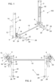
- the apparatus 100 comprises two devices 50, according to the invention, for lifting a load, preferably a motor vehicle.
- the apparatus 100 described below comprises a pair of devices 50, however it is understood that it could also include two or more pairs of devices 50.
- Each device 50 comprises a column structure 2, advantageously with a quadrangular section.
- the column 2 can be provided at the bottom with a plate anchoring to a floor, for example a workshop or a yard.
- the column 2 can be provided at the bottom with means, for example a base with wheels, for its movement within the work room.
- the device 50 also comprises a carriage 8 which is moved/slides along the column 2.
- the carriage 8 is associated with a supporting structure 16 for loading.
- the supporting structure 16 comprises an arm 22 with a substantially longitudinal development and, at each (at least one) end of said longitudinal arm 22, an arm 26 is installed.
- the supporting structure 16 comprises a single longitudinal arm 22.
- the longitudinal arm 22 is straight, but could have longitudinal development with one or more curved sections.
- the supporting structure 16 also comprises arms 26, which are provided at both ends of said longitudinal arm 22 which develop in a direction substantially transverse, or in any case angled, with respect to the axis of said longitudinal arm 22.
- the arms 26 are provided and/or configured to be engaged by members 28 for supporting and/or sustaining the load to be lifted.
- the longitudinal arm 22 is arranged substantially horizontally, while the column 2 develops vertically.
- the longitudinal arm 22 lies on a substantially horizontal plane (or parallel to the supporting floor of the column 2), and is moved with respect to the column 2 and the carriage 8.
- Each lifting device 50 is also provided with means for moving the carriage 8 along said column 2.
- said moving means of the carriage 8 comprise at least one actuator 6, of the electromechanical or hydraulic or pneumatic type, for moving the carriage 8, with the load supporting structure 16, along the column 2 .
- the actuator 6 is housed inside the column 2.
- the actuator 6 can be constituted by a hydraulic jack, with a cylinder fixed to the same column and with a sliding piston inside the cylinder and having the stem protruding upwards and mechanically constrained to the carriage 8, thus causing the latter to slide along the column 2.
- the apparatus 100 also comprises at least one control unit which, preferably, can be defined by a control unit 12, to control the actuator 6 for moving the carriage 8 and/or other actuator elements provided in the device 50.
- each device 50 can be equipped with a control unit, or a single/single control unit can be provided for all the devices 50 of the apparatus 100.
- the control unit can be installed on board the device 50 , or of all the devices 50 of the apparatus 100, or it can be installed externally with respect to the devices 50 of the said apparatus.
- each lifting device 50 of the apparatus 100 can be controlled by its own/dedicated control unit, and that the control units of the devices are connected to each other with cable connections or wireless, preferably Wi-Fi, to ensure synchronism of operation.
- the control of the lifting devices 50 of the apparatus 100 can be of the master-slave type, where one device is set to operate as a master, while the other (or the other) device (s) are set to operate as a slave.
- the apparatus 100 comprises a user interface for controlling and commanding each device 50 of the apparatus itself.
- a single/unic user interface can be provided for all the devices of the apparatus 100, which is mounted on board one or all of the devices or which can be external with respect to the devices (thus operating substantially as a remote control).
- each lifting device 50 can comprise its own dedicated user interface for the control and command of the device itself or of the other devices with which it is connected and in communication.
- the user interface can comprise a display apparatus, for example a screen 14, and a configuration panel provided with input means which can be operatively activated by the operator.
- the user interface may comprise a touch screen and/or a display monitor associated with a keyboard/pushbutton panel.
- each lifting device 50 can also be provided with an electromechanical stop to permanently block the vertical movement of the load supporting structure 16 with respect to the column 2.
- the carriage 8 can be directly connected to a transmission pulley of a chain fixed with one end to the column 2 and with the other end to the carriage 8.
- the stroke of the carriage 8 along the respective column 2 is equal to the elongation of the piston
- the travel of the carriage 8 along the respective column 2 is double with respect to the elongation of the piston.
- the actuators 6 of the facing columns 2 of the respective lifting devices 50 can be synchronized with each other so as to ensure that the carriages 8 move identically along the respective columns 2.
- this synchronization can be obtained in the traditional way by suitable control systems, and in particular with a Master-Slave hydraulic connection in series, with conduits running on the ground and protected by a conduit 10, flattened so as not to obstruct the transit of the motor vehicle to be lifted, or running at high altitude, supported by special air connection structures.
- the two columns 2 of the devices 50 can be connected to each other by means of a conduit 10 positioned in correspondence of the floor and inside which electrical connection cables run between the two devices and/or hydraulic connection pipes between said two devices.
- the conduit 10 containing the electrical connection cables and/or the hydraulic connection pipes could be mounted at the upper ends/areas of the two columns 2.
- the two columns 2 of the devices 50 can be connected to each other by means of an elastic compensation element - for example a spring - which can be associated at the lower ends/areas or - preferably - the upper ends/areas of the two columns 2.
- the elastic element of compensation contains and/or supports the electrical connection cables between the two devices and/or the hydraulic connection pipes between said two devices.
- the elastic element does not cause damage to the devices and/or to the load positioned between them.
- control unit 12 is applied to one of the two columns 2 which, preferably, is electronically connected to a drive motor of a hydraulic pump associated with an oil tank which feeds the actuator jacks 6.
- a series of control buttons for operating the control unit 12 and indicators (for example defined by lights) for signaling the various conditions can be provided on the upper part of the control unit casing, which are suitably viewable in a possible screen 14, which can be applied to the column 2, in a position above the control unit 12.
- the actuator 6 of each column 2 can be powered and controlled by its own control unit, and that the two control units are connected to each other with wireless connections, preferably of the Wi-Fi type, to ensure synchronism of operation.
- the supporting structure is associated with the carriage 8 so as to be able to rotate, relative to the latter, around an axis of articulation that is vertical or substantially vertical.
- the supporting structure 16 comprises a single supporting arm 18 which is articulated to the longitudinal arm 22 and which is also articulated to the carriage 8.
- the supporting arm 18 connects the carriage 8 to the longitudinal arm 22, and in particular to a bracket 20 fixed to the latter.
- the supporting arm 18 is articulated to the the longitudinal arm 22 by means of a bracket 20, which is fixed/integral with the latter while it is articulated to the supporting arm 18.
- the articulation axis of the supporting arm 18 to the carriage 8 and the articulation axis of the supporting arm 18 to the longitudinal arm 22 are parallel to each other and are oriented substantially vertically.
- the supporting arm 18 is configured as a robust arm that supports/sustains the longitudinal arm 22, the arms 26 mounted on the latter, and also the load to be lifted resting on said arms.
- the supporting arm 18 is configured - in terms of shape, dimensions and/or materials - so as to support/sustain substantially by itself the weight of the longitudinal arm 22 and of the arms 26, as well as the weight of the relative load to be lifted.
- the supporting structure 16 also comprises a secondary arm 24 which has no substantial carrying and supporting function of the longitudinal arm 22, of the arms 26 mounted on the latter, and/or of the load to be lifted.
- the secondary arm 24 is articulated to the longitudinal arm 22 and is also articulated to the carriage 8.
- the secondary arm 24 serves substantially to vary the inclination of the longitudinal arm 22 with respect to the supporting arm 18, and in particular therefore allows to varying the angle that the longitudinal arm 22 forms with the supporting arm 18.
- the longitudinal development of the secondary arm 24 can be adjustable - manually or preferably by means of a corresponding actuator mounted and/or associated with the secondary arm 24 - to thus modify the angle defined between the longitudinal arm 22 and the supporting arm 18; suitably, in this way, it is possible to vary the inclination of the longitudinal arm 22 on a corresponding horizontal plane in which the arm lies, to orient it/position it appropriately with respect to the load to be lifted, preferably with respect to the points of grip of said load or of the load. vehicle to be lifted, for example in order to align it or orient it/position it substantially parallel to the side of the vehicle to be lifted.
- the supporting arm 18 is formed from a single piece, it is preferable that the secondary arm 24 is telescopic.
- said secondary arm 24 can be made in two parts which can be screwed together to vary the length of the arm itself and therefore to deform the parallelogram structure during the setting up of the device 50 and/or of the apparatus 100, and this in order to compensate for any installation irregularities of the former.
- the secondary arm 24 is articulated to the carriage 8 in a point/axis of articulation different and distinct from that in which said supporting arm 18 articulates to said carriage 8. More in detail, said supporting arm 18 and said secondary arm 24 are articulated to the carriage 8 around two distinct articulation axes, parallel to each other but spaced apart.
- the secondary arm 24 is associated in an articulated way with the longitudinal arm 22 by means of a corresponding articulation provided on the bracket 20 which is fixed/integral with said longitudinal arm 22 while it is articulated with the secondary arm 24.
- the supporting arm 18 and the secondary arm 24 are articulated to the bracket 20 which is integral with the longitudinal arm 22, or directly to the latter, around two distinct articulation axes which are parallel and spaced apart from each other.
- the supporting structure 16 comprises an articulated parallelogram configuration.
- the secondary arm 24 defines a parallelogram structure with the main supporting arm 18, with the carriage 8 and with the bracket 20, thanks to a suitable choice of the points of articulation between the various elements.
- the articulation axes of said components are parallel to each other and oriented substantially vertically.
- the longitudinal arm 22 comprises a first element 22', in particular tubular with a preferably rectangular section, which is constrained with its central portion, in particular by means of the respective bracket 20 and the supporting arm 18 - and preferably also with the secondary arm 24 - to the corresponding carriage 8.
- the longitudinal arm 22 can comprise a pair of second elements 22", also tubular and configured so as to come out from both ends of the first element 22' and sliding along the latter in order to make the overall length of the arm itself telescopically variable and therefore make it adaptable to vehicles of different characteristics.
- the telescopic lengthening/shortening of the longitudinal arm 22 can be motorized; advantageously, for this purpose, the second elements 22" are associated with suitable handling members, which preferably can be housed inside the first element 22'.
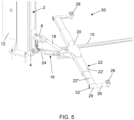
- first element 22' is associated with a single second element 22" removable axially from one end of said element 22', which to the other end bears an arm 26.
- an arm 26 is associated at each (or at least one) end of the longitudinal arm 22, which is telescopic, of the supporting structure 16, an arm 26 is associated.
- the free end of the longitudinal arm 22 - and in particular of the first element 22' and/or at least a second element 22" - an arm 26 is applied.
- the longitudinal development axis of the arm 26 is substantially orthogonal, or in any case angled, with respect to the axis of the longitudinal arm 22.
- each arm 26 is axially movable within a corresponding insertion seat 29 provided in the longitudinal arm 22.
- each insert seat 29 is defined by a tubular section welded to the end of the longitudinal arm 22.
- the insertion seat or seats 29 for the arms 26 develop orthogonally/transversely with respect to the longitudinal development of said longitudinal arm and, preferably, the longitudinal axes which pass through said insertion seat(s) 29 substantially lie on the same horizontal plane (i.e. substantially parallel with respect to the floor on which the column 2 of the device 50 rests).
- the insertion seat or seats 29 for the arms 26 are associated with the longitudinal arm 22 so as to be inclined with respect to the horizontal, and in particular with respect to a horizontal plane on which the arm lies longitudinal, to compensate for any play and deformation.
- each arm 26 and the respective insertion seat 29 is such as to ensure axial mobility of the arm 26 within its insertion seat 29, but to prevent its axial rotation.
- this is preferably achieved by making the arm 26 with a non-circular section and complementary to the section of the seat which houses it.
- each arm 26 one can distinguish the inner end, furthest from the column 2, and the outer end, closest to it.
- each arm 26 is associated with a traditional member 28 for supporting and/or sustaining the load to be lifted; preferably, said member 28 is configured and intended to receive the provided body part of the motor vehicle to be raised in support.
- the member 28 is mounted at the end of each arm 26 furthest from the column 2.
- each arm can be from the constructive and functional point of view substantially of the type described and shown in the Italian patent application no. 102020000006085 .
- the member 28 can be permanently fixed on the arm 26 or, given the considerable diversity between the various motor vehicles, it is advantageous that the support member 28 is removably mounted on the respective arm 26, in order to be replaced with another support member 28 of characteristics more suitable for the vehicle to be lifted; this can be achieved in a very simple way by making each arm 26 with the internal end presenting a hole 30 with a vertical axis and the support member 28 with a lower appendage which can be inserted removably within said hole.
- each arm 26 in its seat at the end of the longitudinal arm 22 is limited towards the outside by the presence of an enlargement, in which the through hole 30 is obtained (see fig. 6 ), and towards the inside by an enlarged head 32.
- the telescopic movements of the two second elements 22" of the longitudinal arm 22 towards the outside also have a limit stop to avoid their complete withdrawal.
- this stop is obtained with an elongated plate 34, applied to the internal end of the corresponding second element 22"and running inside the first element 22'. It is presenting a longitudinal slot 36, in which a transverse pin 38 is fixed, fixed to the central part of the element 22'of the arm 22 (see Figs. 6 and 7 ).
- each device 50 according to the invention can take place as described below.
- the respective column 2 is anchored with its plate 4 to the floor at the predetermined distance from the other device and it is preferable that the vertical surfaces of the two columns, from which the two carriages 8 protrude, are not parallel facing each other, but are oriented towards the front of the motor vehicle to be lifted, since generally the center of gravity of this is located towards its front.
- the arrangement of the various parts is defined so that the longitudinal arms 22 are perfectly parallel to each other and to the longitudinal direction of the passage delimited between the two columns for positioning the motor vehicle to be lifted, but for the purpose to correct possible installation inaccuracies, it is possible to adjust the length of the secondary arms 24 of the two structures 16 with high precision, so as to ensure the perfect orientation of the two longitudinal arms 22.
- the apparatus 100 comprising the two devices 50 according to the invention, it is advantageously ready to work.
- the two carriages 8 are on the ground, the two longitudinal arms 22 are close to the respective columns 2 and are in a condition of minimum elongation, and the arms 26 present at their ends are arranged at the end of the external stroke.
- the two longitudinal arms 22 To lift a motor vehicle, it must be positioned between the two columns 2 in a position suitable for the correct positioning of the two longitudinal arms 22.
- the operator brings the two longitudinal arms 22 closer to the sides of the motor vehicle and to extend them telescopically until the distance between the arms 26 of each longitudinal arm 22 corresponds to the distance between the points of the body, to which the supports 28 must then rest.
- this telescopic extension can be carried out manually, or it can be motorized, if the longitudinal arms 22 are equipped with suitable moving members, and can advantageously be controlled by suitable commands provided in the control unit 12 or also by radio commands, if the control unit it is configured to receive and run them.
- the operator brings the longitudinal arms 22 closer to the motor vehicle until the supports supported by the arms 26 are positioned at the points of the body of the motor vehicle provided for lifting it. Then it axially pushes the arms themselves towards the motor vehicle, so that their supports 28 are positioned exactly below those points.
- the maneuver can be performed manually or it can be motorized and in this case it can be controlled with the command interface associated with the control unit, for example by means of the buttons associated with the control unit 12 or by radio control.
- the vehicle is ready to be lifted.
- corresponding signals are sent to the control unit which thus activates the actuator 6 which causes the carriage 8 to rise until the supports 28 rest on the body of the motor vehicle and then, continuing the upward stroke, raise it to the desired height.
- the control unit 12 activates the pump which introduces oil into the jacks of the actuators 6, which extend, causing the carriages 8 to rise along the respective columns 2 until the supports 28 rest on the body of the motor vehicle and then, continuing the stroke, raise it to the desired height.
- the motor vehicle rests exclusively on the support members 28 and therefore weighs with its weight on the arms 26 and on the longitudinal arms 22 of the devices 50, and thus ensures by friction the locking of the second elements 22" to the respective first elements 22' and arms 26 to the respective second elements 22".
- each supporting arm 18 of the supporting structure 16 can be provided, through which it is possible to control the weight of the raised vehicle.
- the apparatus 100 comprises an optical mechanism for checking the alignment between the respective columns 2 and/or between the carriages 8 of the lifting devices 50, in particular during the lifting movement of the load.
- this optical mechanism comprises a light emitter mounted on a column 2 and a photodetector (for example a photocell) mounted on the other column 2, or on the same column in which the emitter is mounted, and in this case on the other column a reflective element is mounted.
- the optical mechanism is configured to activate automatically by going down by gravity when the carriages 8 of said lifting devices 50 reach a predefined height.
- the emitter/photodetector pair are mounted on a bracket which is vertically movable/sliding along the respective column 2 and which is configured to descend by gravity when the load supported by the supporting structure 16 is raised by the movement vertical upward movement of the carriage 8.
Landscapes
- Life Sciences & Earth Sciences (AREA)
- Engineering & Computer Science (AREA)
- Geology (AREA)
- Mechanical Engineering (AREA)
- Structural Engineering (AREA)
- Forklifts And Lifting Vehicles (AREA)
- Vehicle Cleaning, Maintenance, Repair, Refitting, And Outriggers (AREA)
- Load-Engaging Elements For Cranes (AREA)
- Conveying And Assembling Of Building Elements In Situ (AREA)
Claims (15)
- Vorrichtung (50) zum Heben einer Last, insbesondere zum Heben eines Kraftfahrzeugs, von der Art, die Folgendes umfasst:- eine Säule (2) mit einem Schlitten (8), der entlang der Säule (2) gleitet,- eine Struktur (16), die mit dem Schlitten (8) verbunden ist, um die zu hebende Last zu tragen,- Mittel (6) zum Bewegen des Schlittens (8) entlang der Säule (2), wodurch die Lasttragstruktur (16) angehoben und/oder abgesenkt wird,wobei die Lasttragstruktur (16) umfasst:- einen einzigen Tragarm (18), der an seinem ersten Ende gelenkig mit dem Schlitten (8) verbunden ist,- einen Längsarm (22), der am anderen Ende des Tragarms (18) mit dem Tragarm (18) verbunden ist, so dass er sich in Bezug auf den Tragarm (18) drehen kann,- Arme (26), die an einem oder vorzugsweise an beiden Enden des Längsarms (22) vorgesehen sind und sich in einer im Wesentlichen quer verlaufenden oder in jedem Fall abgewinkelten Richtung in Bezug auf den Längsarm (22) erstrecken, wobei die Arme (26) so vorgesehen und/oder konfiguriert sind, dass sie mit Elementen (28) in Eingriff gebracht werden können, um die zu hebende Last zu stützen und/oder zu tragen,und dadurch gekennzeichnet ist, dass der Längsarm (22) an einem oder vorzugsweise an beiden seiner Enden teleskopisch ist,und dass die Tragstruktur (16) eine gelenkige Parallelogrammkonfiguration umfasst, deren eine Seite durch den Tragarm (18) definiert ist, wobei die gelenkige Parallelogrammkonfiguration der Tragstruktur (16) umfasst:- eine erste Seite, die durch den einzigen Tragarm (18) definiert ist,- eine zweite Seite, die an einem Ende der ersten Seite angelenkt ist und durch einen Abschnitt des Schlittens (8) definiert ist,- eine dritte Seite, die am anderen Ende der ersten Seite angelenkt ist und durch einen Abschnitt des Längsarms (22) definiert ist, und- eine vierte Seite, die aus einem sekundären Arm (24) besteht, der so konfiguriert ist, dass er keine wesentliche lasttragende Funktion hat und so konfiguriert ist, dass er mit den anderen drei Seiten die gelenkige Parallelogrammstruktur (16) definiert.
- Vorrichtung nach Anspruch 1, dadurch gekennzeichnet, dass die Arme (26) an beiden Enden des Längsarms (22) so angebracht sind, dass sie in einer im Wesentlichen quer verlaufenden oder anderweitig abgewinkelten Richtung relativ zu dem Längsarm (22) beweglich sind.
- Vorrichtung nach einem oder mehreren der vorstehenden Ansprüche, dadurch gekennzeichnet, dass der einzelne Tragarm (18) so konfiguriert ist, dass die Bewegungen des Längsarms (22) translatorisch sind und die Längsachse der Längsarm-Entwicklungsachse (22) im Wesentlichen parallel zur Längsachse der zu hebenden Last, insbesondere des Kraftfahrzeugs, gehalten wird.
- Vorrichtung nach einem oder mehreren der vorstehenden Ansprüche, dadurch gekennzeichnet, dass der sekundäre Arm (24) in seiner Länge verstellbar ist.
- Vorrichtung nach einem oder mehreren der vorstehenden Ansprüche, dadurch gekennzeichnet, dass der Tragarm (18) und der sekundäre Arm (24) an dem Schlitten (8) um zwei verschiedene und zueinander parallele Gelenkachsen angelenkt sind.
- Vorrichtung nach einem oder mehreren der vorstehenden Ansprüche, dadurch gekennzeichnet, dass der Tragarm (18) und der sekundäre Arm (24) an einem Ausleger (20), der fest mit dem Längsarm (22) verbunden ist, oder direkt an Letzterem um zwei verschiedene und parallele Gelenkachsen angelenkt sind.
- Vorrichtung nach einem oder mehreren der vorstehenden Ansprüche, dadurch gekennzeichnet, dass die gelenkige Parallelogrammkonfiguration der Tragstruktur (16) so beschaffen ist, dass im Betriebszustand das Ende des einzelnen Tragarms (18), der an dem Längsarm (22) angelenkt ist, näher an dem vorderen Teil des Kraftfahrzeugs liegt als das Ende desselben, das an dem Schlitten (8) angelenkt ist.
- Vorrichtung nach einem oder mehreren der vorstehenden Ansprüche, dadurch gekennzeichnet, dass der Längsarm (22) an seinen Enden mit entsprechenden Einführungssitzen (29) versehen ist, in die entsprechende Arme (26) eingeführt sind, und dass der Eingriff jedes Arms (26) in den entsprechenden Einführungssitz (29) so beschaffen ist, dass er eine axiale Beweglichkeit des Arms (26) in seinem Einführungssitz (29) gewährleistet, aber seine axiale Drehung verhindert.
- Vorrichtung nach einem oder mehreren der vorstehenden Ansprüche, dadurch gekennzeichnet, dass sie Elemente (28) zum Tragen und/oder Stützen der zu hebenden Last umfasst, die an den Armen (26) befestigt sind, oder dadurch, dass die Arme (26) ein Loch (30) umfassen, in das mindestens ein Element (28) zum Tragen und/oder Stützen der zu hebenden Last herausnehmbar eingesetzt werden kann.
- Vorrichtung nach dem vorstehenden Anspruch, dadurch gekennzeichnet, dass:- das mindestens eine zweite ausziehbare Element (22") an einem Ende des Teleskoparms (22) vorgesehen ist und am äußeren Ende Mittel zum Festhalten des Arms (26) aufweist,- der Arm (26) dazu vorgesehen oder dazu bestimmt ist, an seinem in Bezug auf die Säule (2) am weitesten entfernten Ende mit dem Tragelement (28) für die Karosserie eines zu hebenden Kraftfahrzeugs in Eingriff zu kommen, wobei der Arm (26) axial beweglich ist, um das Element (28) unter der Karosserie zu positionieren, und daran gehindert wird, axiale Drehungen auszuführen.
- Vorrichtung nach einem oder mehreren der vorstehenden Ansprüche, dadurch gekennzeichnet, dass sie Begrenzungsmittel umfasst, um ein vollständiges Entfernen mindestens eines zweiten Elements (22") aus dem ersten Element (22') zu verhindern, wobei die Begrenzungsmittel des Hubs am inneren Ende des zweiten Elements (22") vorgesehen sind und im Inneren des ersten rohrförmigen Elements (22') untergebracht sind.
- Vorrichtung nach Anspruch 11, dadurch gekennzeichnet, dass die Endanschlagmittel Folgendes einschließen:- einen Längsschlitz (36), der am inneren Ende des mindestens zweiten abnehmbaren Elements (22") des Teleskoparms (22) vorgesehen ist und innerhalb des ersten rohrförmigen Elements (22') verläuft, und- einen Querstift (38), der an dem ersten rohrförmigen Element (22') befestigt ist und der den Längsschlitz (36) in Gleiteingriff nimmt.
- Vorrichtung nach Anspruch 11 oder 12, dadurch gekennzeichnet, dass die Endanschlagmittel Folgendes einschließen:- einen Querstift (38), der am inneren Ende des mindestens zweiten abnehmbaren Elements (22") des Teleskoparms (22) vorgesehen ist und im Inneren des ersten rohrförmigen Elements (22') untergebracht ist- einen Längsschlitz (36), der an dem ersten rohrförmigen Element (22') befestigt ist und den der Querstift (38) in Gleiteingriff nimmt.
- Vorrichtung (100) zum Heben einer Last, insbesondere zum Heben eines Kraftfahrzeugs, vorzugsweise eines Elektrofahrzeugs, dadurch gekennzeichnet, dass sie mindestens ein Paar Hebevorrichtungen (50) nach einem oder mehreren der vorstehenden Ansprüche umfasst.
- Vorrichtung nach Anspruch 14, dadurch gekennzeichnet, dass jede Vorrichtung (50) mit einer eigenen Steuereinheit (12) versehen ist, die über Kabel oder drahtlos mit der anderen Steuervorrichtung (50) verbunden ist.
Applications Claiming Priority (2)
| Application Number | Priority Date | Filing Date | Title |
|---|---|---|---|
| IT102019000006900A IT201900006900A1 (it) | 2019-05-16 | 2019-05-16 | Dispositivo a colonna per il sollevamento di un carico. |
| PCT/IB2020/054578 WO2020230079A1 (en) | 2019-05-16 | 2020-05-14 | Device for lifting a load |
Publications (3)
| Publication Number | Publication Date |
|---|---|
| EP3969403A1 EP3969403A1 (de) | 2022-03-23 |
| EP3969403C0 EP3969403C0 (de) | 2025-01-08 |
| EP3969403B1 true EP3969403B1 (de) | 2025-01-08 |
Family
ID=67660761
Family Applications (1)
| Application Number | Title | Priority Date | Filing Date |
|---|---|---|---|
| EP20731954.2A Active EP3969403B1 (de) | 2019-05-16 | 2020-05-14 | Vorrichtung zum heben einer last |
Country Status (9)
| Country | Link |
|---|---|
| US (1) | US11661323B2 (de) |
| EP (1) | EP3969403B1 (de) |
| JP (1) | JP7606756B2 (de) |
| CN (1) | CN114096482A (de) |
| CA (1) | CA3140605A1 (de) |
| ES (1) | ES3021810T3 (de) |
| IT (1) | IT201900006900A1 (de) |
| PL (1) | PL3969403T3 (de) |
| WO (1) | WO2020230079A1 (de) |
Families Citing this family (7)
| Publication number | Priority date | Publication date | Assignee | Title |
|---|---|---|---|---|
| IT201900006900A1 (it) * | 2019-05-16 | 2020-11-16 | O Me R Spa | Dispositivo a colonna per il sollevamento di un carico. |
| DE102020135143B4 (de) | 2020-12-30 | 2023-02-16 | Gerhard Finkbeiner | Hebevorrichtung sowie Hebebühne zum Heben und Senken von Fahrzeugen oder Lasten |
| DE102021113330A1 (de) | 2021-05-21 | 2022-11-24 | Gerhard Finkbeiner | Hebevorrichtung sowie Hebebühne zum Heben und Senken von Lasten oder Fahrzeugen |
| US20230090066A1 (en) * | 2021-09-17 | 2023-03-23 | Fritel & Associates, LLC | Trailer stacking device |
| US12030756B2 (en) * | 2021-10-25 | 2024-07-09 | Vehicle Service Group Italy, S.R.L. | Vehicle lift |
| WO2023178016A1 (en) | 2022-03-15 | 2023-09-21 | BendPak, Inc. | Two post lift with reversible offset telescoping lift arms |
| USD1069528S1 (en) * | 2022-10-13 | 2025-04-08 | Gabriel Del Valle | Lift pad centering tool |
Family Cites Families (24)
| Publication number | Priority date | Publication date | Assignee | Title |
|---|---|---|---|---|
| ES357815A1 (es) * | 1968-07-26 | 1970-03-16 | Tranchero | Perfeccionamientos relativo a las maquinas moviles para la elevacion de cargas en general, especialmente autovehiculos,a alturas limitadas. |
| JPS5249544A (en) * | 1975-10-17 | 1977-04-20 | Yasaka Seiki Kk | Vehicle lifting device |
| JPS5822769A (ja) * | 1981-07-31 | 1983-02-10 | Suzuki Tanko Co Ltd | 農業トラクタ−用リフト装置とトレ−ラ− |
| JPH0450311Y2 (de) * | 1986-09-30 | 1992-11-26 | ||
| JP2523385Y2 (ja) * | 1993-02-08 | 1997-01-22 | 日産アルティア株式会社 | 車両用リフト装置 |
| JPH07196292A (ja) * | 1993-12-29 | 1995-08-01 | Banzai Kogyo Kk | 同調式車両用リフト |
| US5984616A (en) * | 1996-11-21 | 1999-11-16 | Prime Technologies, Inc. | Variable pivot towing device |
| WO2010002968A1 (en) | 2008-07-03 | 2010-01-07 | Rotary Lift, A Division Of Dover Industrial Products, Inc. | Vehicle guidance system for automotive lifts |
| DE202009007646U1 (de) | 2009-06-01 | 2009-08-06 | JINHUA Auto Equipment Manufacturing Co., Ltd., Qingdao | Zwei Säulen Hydraulische Balenciert Hebebühne |
| JP2011190094A (ja) | 2010-03-16 | 2011-09-29 | Kawasaki Heavy Ind Ltd | 昇降装置 |
| DE102010045287A1 (de) | 2010-09-14 | 2012-03-15 | Otto Nussbaum Gmbh & Co. Kg | Hebebühne für Kraftfahrzeuge |
| US11305972B1 (en) * | 2011-11-11 | 2022-04-19 | Vehcile Service Group, Llc | Vehicle lift with locally stored energy source |
| DE202013102803U1 (de) * | 2013-06-27 | 2014-09-29 | Gerhard Finkbeiner | Hebevorrichtung zum Heben und Senken von Fahrzeugen |
| US9764933B2 (en) | 2013-12-12 | 2017-09-19 | Macton Corporation | Machinery positioning apparatus having independent drive columns |
| US9821989B2 (en) | 2014-02-17 | 2017-11-21 | Vehicle Service Group, Llc | Adjustable overhead assembly for vehicle lift |
| US10081523B2 (en) * | 2014-05-15 | 2018-09-25 | Vehicle Service Group, Llc | Load indicator for vehicle lift |
| GB2526356B (en) | 2014-05-23 | 2018-08-01 | Abt Products Ltd | A forklift arrangement with parallel linkage |
| JP6395254B2 (ja) * | 2014-08-26 | 2018-09-26 | 株式会社ヤスヰ | 車両用リフト装置 |
| GB2536272A (en) | 2015-03-12 | 2016-09-14 | Autotrade Solutions Ltd | Vehicle lift |
| US10676332B2 (en) | 2015-10-21 | 2020-06-09 | Vehicle Service Group, Llc | Setup and control of a wireless lift system |
| US10081524B2 (en) * | 2016-09-15 | 2018-09-25 | Gray Manufacturing Company, Inc. | Monitoring system for two-post lift |
| DE102018105573A1 (de) * | 2018-03-12 | 2019-09-12 | Otto Nussbaum Gmbh & Co. Kg | Hebebühne für kraftfahrzeuge |
| IT201900006900A1 (it) * | 2019-05-16 | 2020-11-16 | O Me R Spa | Dispositivo a colonna per il sollevamento di un carico. |
| WO2021081249A1 (en) * | 2019-10-22 | 2021-04-29 | Automotive Lift Institute | Automotive lift and swing arm restraint system for automotive lift |
-
2019
- 2019-05-16 IT IT102019000006900A patent/IT201900006900A1/it unknown
-
2020
- 2020-05-14 WO PCT/IB2020/054578 patent/WO2020230079A1/en not_active Ceased
- 2020-05-14 ES ES20731954T patent/ES3021810T3/es active Active
- 2020-05-14 CN CN202080050324.XA patent/CN114096482A/zh active Pending
- 2020-05-14 EP EP20731954.2A patent/EP3969403B1/de active Active
- 2020-05-14 CA CA3140605A patent/CA3140605A1/en active Pending
- 2020-05-14 US US17/609,027 patent/US11661323B2/en active Active
- 2020-05-14 PL PL20731954.2T patent/PL3969403T3/pl unknown
- 2020-05-14 JP JP2021567922A patent/JP7606756B2/ja active Active
Also Published As
| Publication number | Publication date |
|---|---|
| WO2020230079A1 (en) | 2020-11-19 |
| ES3021810T3 (en) | 2025-05-27 |
| EP3969403A1 (de) | 2022-03-23 |
| EP3969403C0 (de) | 2025-01-08 |
| JP2022533944A (ja) | 2022-07-27 |
| PL3969403T3 (pl) | 2025-06-09 |
| IT201900006900A1 (it) | 2020-11-16 |
| CA3140605A1 (en) | 2020-11-19 |
| JP7606756B2 (ja) | 2024-12-26 |
| US20220212907A1 (en) | 2022-07-07 |
| CN114096482A (zh) | 2022-02-25 |
| US11661323B2 (en) | 2023-05-30 |
Similar Documents
| Publication | Publication Date | Title |
|---|---|---|
| EP3969403B1 (de) | Vorrichtung zum heben einer last | |
| KR101580528B1 (ko) | 고소작업대가 구비된 구조물 조립용 트롤리 | |
| US10676334B2 (en) | Anti-pothole aerial work platform | |
| CN105143575B (zh) | 建筑系统 | |
| US4801237A (en) | Transportation device for commercial and industrial use | |
| US10710852B2 (en) | Portable auto rack | |
| JPH02500829A (ja) | エアブリツジ | |
| JPH11310396A (ja) | 移動式昇降作業台用垂直マストの横ジブ | |
| HK40070270A (en) | Device for lifting a load | |
| HK40070270B (en) | Device for lifting a load | |
| RU2799087C2 (ru) | Устройство для подъема груза | |
| KR102756067B1 (ko) | 리프팅 시스템과 리프팅 시스템 제어 방법 및 리프팅 시스템의 제어 시스템 | |
| CN113929031A (zh) | 一种具有高安全性能的矿井升降设备 | |
| KR20210047642A (ko) | 2주식 리프트의 받침아암장치 | |
| JP6865151B2 (ja) | 重量物搬送台車 | |
| JPWO2020230079A5 (de) | ||
| US11498818B2 (en) | Vehicle support assembly | |
| WO2005077711A1 (en) | Pipe handling apparatus | |
| JP2002362890A (ja) | 昇降装置 | |
| EP1724232A2 (de) | Hebevorrichtung für Motorräder | |
| WO2006122735A1 (en) | Lift device of column type | |
| CN113998633B (zh) | 基于举升车的型材举升方法 | |
| CN220011926U (zh) | 一种配重假人移动装置 | |
| GB2398556A (en) | Pipe handling apparatus | |
| US20230311774A1 (en) | Guard rail assembly and method of use thereof |
Legal Events
| Date | Code | Title | Description |
|---|---|---|---|
| STAA | Information on the status of an ep patent application or granted ep patent |
Free format text: STATUS: UNKNOWN |
|
| STAA | Information on the status of an ep patent application or granted ep patent |
Free format text: STATUS: THE INTERNATIONAL PUBLICATION HAS BEEN MADE |
|
| PUAI | Public reference made under article 153(3) epc to a published international application that has entered the european phase |
Free format text: ORIGINAL CODE: 0009012 |
|
| STAA | Information on the status of an ep patent application or granted ep patent |
Free format text: STATUS: REQUEST FOR EXAMINATION WAS MADE |
|
| 17P | Request for examination filed |
Effective date: 20211213 |
|
| AK | Designated contracting states |
Kind code of ref document: A1 Designated state(s): AL AT BE BG CH CY CZ DE DK EE ES FI FR GB GR HR HU IE IS IT LI LT LU LV MC MK MT NL NO PL PT RO RS SE SI SK SM TR |
|
| DAV | Request for validation of the european patent (deleted) | ||
| DAX | Request for extension of the european patent (deleted) | ||
| REG | Reference to a national code |
Ref country code: HK Ref legal event code: DE Ref document number: 40070270 Country of ref document: HK |
|
| P01 | Opt-out of the competence of the unified patent court (upc) registered |
Effective date: 20230519 |
|
| GRAP | Despatch of communication of intention to grant a patent |
Free format text: ORIGINAL CODE: EPIDOSNIGR1 |
|
| STAA | Information on the status of an ep patent application or granted ep patent |
Free format text: STATUS: GRANT OF PATENT IS INTENDED |
|
| INTG | Intention to grant announced |
Effective date: 20240820 |
|
| GRAS | Grant fee paid |
Free format text: ORIGINAL CODE: EPIDOSNIGR3 |
|
| GRAA | (expected) grant |
Free format text: ORIGINAL CODE: 0009210 |
|
| STAA | Information on the status of an ep patent application or granted ep patent |
Free format text: STATUS: THE PATENT HAS BEEN GRANTED |
|
| AK | Designated contracting states |
Kind code of ref document: B1 Designated state(s): AL AT BE BG CH CY CZ DE DK EE ES FI FR GB GR HR HU IE IS IT LI LT LU LV MC MK MT NL NO PL PT RO RS SE SI SK SM TR |
|
| REG | Reference to a national code |
Ref country code: GB Ref legal event code: FG4D |
|
| REG | Reference to a national code |
Ref country code: CH Ref legal event code: EP |
|
| REG | Reference to a national code |
Ref country code: DE Ref legal event code: R096 Ref document number: 602020044490 Country of ref document: DE |
|
| REG | Reference to a national code |
Ref country code: IE Ref legal event code: FG4D |
|
| P04 | Withdrawal of opt-out of the competence of the unified patent court (upc) registered |
Free format text: CASE NUMBER: APP_5990/2025 Effective date: 20250204 |
|
| U01 | Request for unitary effect filed |
Effective date: 20250131 |
|
| U07 | Unitary effect registered |
Designated state(s): AT BE BG DE DK EE FI FR IT LT LU LV MT NL PT RO SE SI Effective date: 20250207 |
|
| REG | Reference to a national code |
Ref country code: ES Ref legal event code: FG2A Ref document number: 3021810 Country of ref document: ES Kind code of ref document: T3 Effective date: 20250527 |
|
| U20 | Renewal fee for the european patent with unitary effect paid |
Year of fee payment: 6 Effective date: 20250512 |
|
| PG25 | Lapsed in a contracting state [announced via postgrant information from national office to epo] |
Ref country code: RS Free format text: LAPSE BECAUSE OF FAILURE TO SUBMIT A TRANSLATION OF THE DESCRIPTION OR TO PAY THE FEE WITHIN THE PRESCRIBED TIME-LIMIT Effective date: 20250408 |
|
| PGFP | Annual fee paid to national office [announced via postgrant information from national office to epo] |
Ref country code: PL Payment date: 20250513 Year of fee payment: 6 |
|
| PGFP | Annual fee paid to national office [announced via postgrant information from national office to epo] |
Ref country code: GB Payment date: 20250512 Year of fee payment: 6 Ref country code: ES Payment date: 20250610 Year of fee payment: 6 |
|
| PG25 | Lapsed in a contracting state [announced via postgrant information from national office to epo] |
Ref country code: IS Free format text: LAPSE BECAUSE OF FAILURE TO SUBMIT A TRANSLATION OF THE DESCRIPTION OR TO PAY THE FEE WITHIN THE PRESCRIBED TIME-LIMIT Effective date: 20250508 |
|
| PGFP | Annual fee paid to national office [announced via postgrant information from national office to epo] |
Ref country code: NO Payment date: 20250513 Year of fee payment: 6 |
|
| PG25 | Lapsed in a contracting state [announced via postgrant information from national office to epo] |
Ref country code: HR Free format text: LAPSE BECAUSE OF FAILURE TO SUBMIT A TRANSLATION OF THE DESCRIPTION OR TO PAY THE FEE WITHIN THE PRESCRIBED TIME-LIMIT Effective date: 20250108 |
|
| PG25 | Lapsed in a contracting state [announced via postgrant information from national office to epo] |
Ref country code: GR Free format text: LAPSE BECAUSE OF FAILURE TO SUBMIT A TRANSLATION OF THE DESCRIPTION OR TO PAY THE FEE WITHIN THE PRESCRIBED TIME-LIMIT Effective date: 20250409 |
|
| PGFP | Annual fee paid to national office [announced via postgrant information from national office to epo] |
Ref country code: CH Payment date: 20250601 Year of fee payment: 6 |
|
| PGFP | Annual fee paid to national office [announced via postgrant information from national office to epo] |
Ref country code: TR Payment date: 20250513 Year of fee payment: 6 |
|
| PG25 | Lapsed in a contracting state [announced via postgrant information from national office to epo] |
Ref country code: SM Free format text: LAPSE BECAUSE OF FAILURE TO SUBMIT A TRANSLATION OF THE DESCRIPTION OR TO PAY THE FEE WITHIN THE PRESCRIBED TIME-LIMIT Effective date: 20250108 |
|
| PG25 | Lapsed in a contracting state [announced via postgrant information from national office to epo] |
Ref country code: CZ Free format text: LAPSE BECAUSE OF FAILURE TO SUBMIT A TRANSLATION OF THE DESCRIPTION OR TO PAY THE FEE WITHIN THE PRESCRIBED TIME-LIMIT Effective date: 20250108 |
|
| PG25 | Lapsed in a contracting state [announced via postgrant information from national office to epo] |
Ref country code: SK Free format text: LAPSE BECAUSE OF FAILURE TO SUBMIT A TRANSLATION OF THE DESCRIPTION OR TO PAY THE FEE WITHIN THE PRESCRIBED TIME-LIMIT Effective date: 20250108 |
|
| PLBE | No opposition filed within time limit |
Free format text: ORIGINAL CODE: 0009261 |
|
| STAA | Information on the status of an ep patent application or granted ep patent |
Free format text: STATUS: NO OPPOSITION FILED WITHIN TIME LIMIT |