EP3969191B1 - Vorrichtung zur verwendung eines produktes zum absorbieren von verschütteten fluiden, einschliesslich recycling des produktes - Google Patents
Vorrichtung zur verwendung eines produktes zum absorbieren von verschütteten fluiden, einschliesslich recycling des produktes Download PDFInfo
- Publication number
- EP3969191B1 EP3969191B1 EP20731929.4A EP20731929A EP3969191B1 EP 3969191 B1 EP3969191 B1 EP 3969191B1 EP 20731929 A EP20731929 A EP 20731929A EP 3969191 B1 EP3969191 B1 EP 3969191B1
- Authority
- EP
- European Patent Office
- Prior art keywords
- receptacle
- sieving
- container
- product
- tank
- Prior art date
- Legal status (The legal status is an assumption and is not a legal conclusion. Google has not performed a legal analysis and makes no representation as to the accuracy of the status listed.)
- Active
Links
Images


Classifications
-
- B—PERFORMING OPERATIONS; TRANSPORTING
- B07—SEPARATING SOLIDS FROM SOLIDS; SORTING
- B07B—SEPARATING SOLIDS FROM SOLIDS BY SIEVING, SCREENING, SIFTING OR BY USING GAS CURRENTS; SEPARATING BY OTHER DRY METHODS APPLICABLE TO BULK MATERIAL, e.g. LOOSE ARTICLES FIT TO BE HANDLED LIKE BULK MATERIAL
- B07B1/00—Sieving, screening, sifting, or sorting solid materials using networks, gratings, grids, or the like
- B07B1/02—Hand screens
-
- B—PERFORMING OPERATIONS; TRANSPORTING
- B07—SEPARATING SOLIDS FROM SOLIDS; SORTING
- B07B—SEPARATING SOLIDS FROM SOLIDS BY SIEVING, SCREENING, SIFTING OR BY USING GAS CURRENTS; SEPARATING BY OTHER DRY METHODS APPLICABLE TO BULK MATERIAL, e.g. LOOSE ARTICLES FIT TO BE HANDLED LIKE BULK MATERIAL
- B07B1/00—Sieving, screening, sifting, or sorting solid materials using networks, gratings, grids, or the like
- B07B1/005—Transportable screening plants
-
- B—PERFORMING OPERATIONS; TRANSPORTING
- B07—SEPARATING SOLIDS FROM SOLIDS; SORTING
- B07B—SEPARATING SOLIDS FROM SOLIDS BY SIEVING, SCREENING, SIFTING OR BY USING GAS CURRENTS; SEPARATING BY OTHER DRY METHODS APPLICABLE TO BULK MATERIAL, e.g. LOOSE ARTICLES FIT TO BE HANDLED LIKE BULK MATERIAL
- B07B13/00—Grading or sorting solid materials by dry methods, not otherwise provided for; Sorting articles otherwise than by indirectly controlled devices
- B07B13/14—Details or accessories
- B07B13/16—Feed or discharge arrangements
-
- B—PERFORMING OPERATIONS; TRANSPORTING
- B09—DISPOSAL OF SOLID WASTE; RECLAMATION OF CONTAMINATED SOIL
- B09C—RECLAMATION OF CONTAMINATED SOIL
- B09C1/00—Reclamation of contaminated soil
Definitions
- the present invention relates to a device for using an absorbent product in powder or granule form, as well as a method for implementing such a device.
- the absorbent product swollen by the fluid is then collected, for example by sweeping, to remove most of the fluid spilled on the floor. Finally, if necessary, a solvent or cleaning product such as detergent can be applied to the floor to ensure that the floor is clean.
- trolleys equipped with all the necessary elements, including a storage bin containing the absorbent product, a receiving bin receiving the soiled absorbent product, and the different tools necessary to carry out these operations such as a broom and a shovel.
- the cleaning staff can move quickly to the scene of the incident to first recover as much of the spilled fluid as possible with the absorbent product, then collect and dispose of this soiled product in the receiving bin. Once the receiving bin is full, the soiled product can be recovered and treated by specialized companies in the best conditions of safety and respect for the environment.
- the document GB2346077 A discloses a device according to the preamble of claim 1.
- the present invention aims in particular to avoid these drawbacks of the prior art.
- a device for using an absorbent product in particular in powder or granule form, to absorb fluids spilled on the ground according to claim 1, comprising a container equipped with a storage tank for this absorbent product, and a tank for receiving the soiled absorbent product, this device being remarkable in that it comprises a sieving receptacle comprising at the bottom a sieve arranged above an opening of the storage tank, which can be emptied into the receiving tank.
- An advantage of the device according to the invention is that after spreading the absorbent product on the ground, the operator simply pours this soiled product into the receptacle equipped with the sieve, then with a vibration obtains a sieving of this product allowing the unsoiled powder or granules to pass through remaining in the form of fine particles, which descend and are recycled in the storage bin. Once this sieving is finished, the operator tilts the receptacle to pour into the receiving bin the remaining product actually soiled, which has agglomerated to form lumps.
- the device for using the absorbent product according to the invention may further comprise one or more of the following characteristics, which may be combined with each other.
- the opening of the storage bin corresponds to the outer contour of this storage bin.
- the screening receptacle has a guide in the container.
- the screening receptacle comprises external shoulders which come above bosses formed inside the container.
- the screening receptacle comprises a handle arranged on a front face of the container, the guidance in the container being carried out in a direction perpendicular to this front face.
- the receiving tray is arranged next to the screening receptacle.
- the screening receptacle has on the upper part of one of its sides a horizontal chute whose end comes above the receiving tank.
- the screening receptacle comprises a shape which rests on an edge of the receiving bin, constituting a pivot allowing the chute to be poured into this receiving bin.
- the sieving receptacle has a sieve with bumps at the bottom.
- the invention also relates to a method for implementing a device for using an absorbent product, in particular in powder or granule form, according to claim 8, comprising an operation of shaking the sieving receptacle along guides above the storage tank, then an operation of tilting the sieving receptacle emptying lumps formed by the soiled product into the receiving tank, and finally an operation of returning the sieving receptacle to its position above the storage tank.
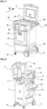
- FIGS. 1 and 2 present a trolley comprising a container 2 having a vertically elongated parallelepiped shape, having a cover 4 fixed by a hinge 6 at the top of the rear side of this container indicated by the arrow AR.
- the base on the right side has an axis arranged along the length receiving two fixed casters 8
- the base on the left side has at each corner a swivel caster along a vertical axis 10 to ensure the mobility of the trolley in all directions.
- the left side of the container 2 has a cell 16 in the upper part which also allows bottles to be accommodated there.
- the right side has an opening 20 at the bottom leading to a lower compartment occupying approximately a quarter of the height of the container 2, allowing various products to be accommodated there.
- a storage bin 22 for an absorbent product in powder or granule form has a front face fitted to the front face of the container, sides fitted inside the right and left sides of the container, and a rear face arranged approximately two-thirds of the length of this container.
- the storage bin 22 is connected to the container 2 by a lower pivot arranged along the width allowing it to tilt forward as shown. figure 2 , a handle 24 formed on the upper part of its front face facilitating this traction.
- Each side of the container 2 has on its inner face a cleat 26 which descends slightly inside the storage bin 22, coming onto an inner shoulder of the bin when it is fully tilted forward in order to prevent this bin from falling.
- the storage bin 22 can be easily opened by pulling it by its handle 24, to release its upper opening forward and to fill it.
- a screening receptacle 30 has a substantially rectangular shape fitting within the width of the container 2, having a forward-facing handle 32 which facilitates its gripping and movement.
- the screening receptacle 30 comprises on each side along its length a horizontal external shoulder 34, forming an overhang which rests on a corresponding boss 36 formed inside the right and left side of the container 2, to constitute guide rails along the length of this container comprising stops at the ends.
- the sieving receptacle 30 comprises a horizontal bottom forming a lower sieve 38, having a passage surface which remains inside the opening of the storage bin 22 during movements using the handle 32 of this receptacle, limited by its stops, to ensure that all of the absorbent product passing through the sieve falls into this bin.
- the sieve 38 has a generally flat horizontal surface comprising bumps distributed over this surface.
- a container for receiving soiled absorbent product 40 having a parallelepiped shape elongated in height has a width fitting inside the two sides of the container 2, a length corresponding to approximately a quarter of the length of this container, and a height corresponding to approximately half the height of the container.
- the rear upper edge of the storage bin 22 has a rearward-facing spoiler 28, which bears on the front face of the receiving bin 40 in order to completely close the passage between these two bins to prevent descents of absorbent product which would fall between them, outside the storage tank.
- the screening receptacle 30 comprises in the upper part of its rear face a horizontal chute 42 extending over the entire width of this rear face, which ends substantially in the middle of the receiving bin 40.
- the receiving bin 40 and the screening receptacle 30 are easily removed by lifting them out of the container 2.
- All of the components of the trolley including in particular the container 2 formed of several assembled panels each constituting a side, the cover 4, the storage bin 22, the sieving receptacle 30 with its sieve 38 and the receiving bin 40, are formed by a plastic molding which makes it possible to economically produce rigid and lightweight elements.
- the operator has on the trolley containing absorbent product in the storage bin 22, a broom, a shovel, cleaning product and accessories such as cloths, so that during an intervention he has all the equipment necessary to pick up a spilled fluid and clean the floor.
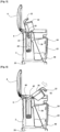
- the operator grasps the handle 32 of the sieving receptacle 30, and applies a vigorous alternating movement along the length by sliding it on its rails to obtain a descent through the sieve 38 of the absorbent product 50 which has not been in contact with the fluid, remaining in the form of powder or granules fine enough not to pass through the sieve.
- the embossing of the sieve 38 facilitates the movement and sorting of the absorbent product, by rolling the lumps 52 formed by the powder or granules agglomerated by the absorbed fluid, and by clearing the meshes of the sieve to allow the clean product to pass through.
- the operator lifts the handle 32, tilting the screening receptacle 30 about a pivot formed by the junction of the chute 42 with the rear face of the screening receptacle 30, rotating about the upper front edge of the receiving bin 40. In this way the screening receptacle 30 is guided, letting the rear end of its chute 42 descend into the receiving bin 40.
- FIG 5 presents a following operation comprising the complete tilting of the sieving receptacle 30, coming into a substantially vertical position, all of the lumps 52 descending into the receiving bin 40.
- the figure 6 presents a following operation comprising the reverse tilting of the sieving receptacle 30 which is empty.
- a subsequent emptying operation of the receiving bin 40 is easily done by lifting the sieving receptacle 30, and the receiving bin 40 which slides vertically to be emptied.
- Another subsequent filling operation of the storage bin 22 is easily done by pulling its handle 24 to tilt it forward, which releases its upper opening allowing it to be filled for example with a shovel, or by emptying a bag into it.
Landscapes
- Life Sciences & Earth Sciences (AREA)
- Soil Sciences (AREA)
- Engineering & Computer Science (AREA)
- Environmental & Geological Engineering (AREA)
- Combined Means For Separation Of Solids (AREA)
- Housing For Livestock And Birds (AREA)
Claims (8)
- Vorrichtung zur Verwendung eines absorbierenden Produkts (50), insbesondere in Form von Pulver oder Granulat, um auf dem Boden verteilte Fluide zu absorbieren, umfassend einen Behälter (2), der mit einem Vorratstank (22) für das absorbierende Produkt (50) ausgestattet ist, und einen Aufnahmetank (40) für das verschmutzte absorbierende Produkt (52), wobei die Vorrichtung ein Siebbehältnis (30) enthält, das am Boden ein Sieb (38) umfasst, das über einer Öffnung des Vorratstanks (22) angeordnet ist und in den Aufnahmetank (40) geleert werden kann, dadurch gekennzeichnet, dass das Siebbehältnis (30) eine Führung im Behälter (2) und äußere Schultern (34) enthält, die über entsprechenden Vorsprüngen (36) liegen, die an der Innenseite einer rechten Seite und einer linken Seite des Behälters (2) ausgebildet sind, wobei die Vorsprünge (36) Führungsschienen entlang der Länge des Behälters (2) bilden.
- Verwendungsvorrichtung nach Anspruch 1, dadurch gekennzeichnet, dass die Öffnung des Vorratstanks (22) der vollständigen Außenkontur des Vorratstanks (22) entspricht.
- Verwendungsvorrichtung nach Anspruch 1 oder 2, dadurch gekennzeichnet, dass das Siebbehältnis (30) einen Griff (32) enthält, der an einer Vorderseite des Behälters (2) angeordnet ist, wobei die Führung im Behälter (2) in einer Richtung senkrecht zu der Vorderseite erfolgt.
- Verwendungsvorrichtung nach einem der vorhergehenden Ansprüche, dadurch gekennzeichnet, dass der Aufnahmetank (40) neben dem Siebbehältnis (30) angeordnet ist.
- Verwendungsvorrichtung nach Anspruch 4, dadurch gekennzeichnet, dass das Siebbehältnis (30) im oberen Teil einer seiner Seiten eine horizontale Rutsche (42) enthält, deren Ende über dem Aufnahmetank (40) liegt.
- Verwendungsvorrichtung nach Anspruch 5, dadurch gekennzeichnet, dass das Siebbehältnis (30) eine Form enthält, die an einem Rand des Aufnahmetanks (40) anliegt und einen Drehpunkt bildet, der es ermöglicht, die Rutsche (42) in den Aufnahmetank (40) zu schütten.
- Verwendungsvorrichtung nach einem der vorhergehenden Ansprüche, dadurch gekennzeichnet, dass das Siebbehältnis (30) am Boden ein Sieb (38) enthält, das Vorsprünge aufweist.
- Verfahren zum Implementieren einer Vorrichtung zum Verwenden eines absorbierenden Produkts aus Pulver oder Granulat (50) nach einem der vorhergehenden Ansprüche, wobei das Verfahren einen Vorgang des Schüttelns des Siebbehältnisses (30) entlang von Führungen über dem Vorratstank (22) und anschließend einen Vorgang des Kippens des Siebbehältnisses (30) zum Entleeren von Klumpen (52), die durch das verschmutzte Produkt im Aufnahmetank (40) gebildet werden, und schließlich einen Vorgang umfasst, bei dem das Siebbehältnis (30) wieder über dem Vorratstank (22) in Position gebracht wird.
Applications Claiming Priority (2)
| Application Number | Priority Date | Filing Date | Title |
|---|---|---|---|
| FR1905179A FR3095961B1 (fr) | 2019-05-17 | 2019-05-17 | Dispositif d’utilisation d’un produit d’absorption de fluides repandus avec recyclage de ce produit |
| PCT/FR2020/050745 WO2020234522A1 (fr) | 2019-05-17 | 2020-05-05 | Dispositif d´utilisation d´un produit d´absorption de fluides repandus avec recyclage de ce produit |
Publications (3)
| Publication Number | Publication Date |
|---|---|
| EP3969191A1 EP3969191A1 (de) | 2022-03-23 |
| EP3969191C0 EP3969191C0 (de) | 2024-11-06 |
| EP3969191B1 true EP3969191B1 (de) | 2024-11-06 |
Family
ID=67999819
Family Applications (1)
| Application Number | Title | Priority Date | Filing Date |
|---|---|---|---|
| EP20731929.4A Active EP3969191B1 (de) | 2019-05-17 | 2020-05-05 | Vorrichtung zur verwendung eines produktes zum absorbieren von verschütteten fluiden, einschliesslich recycling des produktes |
Country Status (4)
| Country | Link |
|---|---|
| US (1) | US12017253B2 (de) |
| EP (1) | EP3969191B1 (de) |
| FR (1) | FR3095961B1 (de) |
| WO (1) | WO2020234522A1 (de) |
Families Citing this family (1)
| Publication number | Priority date | Publication date | Assignee | Title |
|---|---|---|---|---|
| US20240407321A1 (en) * | 2023-06-12 | 2024-12-12 | Kenneth Lewis Taylor, JR. | Lift to Sift Litter Box |
Family Cites Families (9)
| Publication number | Priority date | Publication date | Assignee | Title |
|---|---|---|---|---|
| GB268657A (en) * | 1926-10-09 | 1927-04-07 | Alfred James Beall | A combined detachable dustbin extension and sieve cradle |
| GB588039A (en) * | 1944-08-08 | 1947-05-13 | George Frederick Tilke | Improvements in or relating to sifting apparatus |
| US5785000A (en) * | 1997-07-18 | 1998-07-28 | Barbary; Daniel J. | Kitty litter assembly |
| GB9827760D0 (en) * | 1998-12-17 | 1999-02-10 | Oil Cleaning Bio Products Limi | Apparatus |
| US8683952B2 (en) * | 2010-05-27 | 2014-04-01 | Matthew J. Miller | Cat litter box system |
| US9807976B2 (en) * | 2015-02-06 | 2017-11-07 | Process4, Inc. | Closeable container cap |
| US20160295828A1 (en) * | 2015-04-09 | 2016-10-13 | Mark J. Fenwick | Animal Litter Box |
| US9550214B2 (en) * | 2015-05-06 | 2017-01-24 | Bryan Harpel | Sorting and bagging apparatus and method |
| CN106595243A (zh) * | 2016-12-30 | 2017-04-26 | 天津横天生物科技有限公司 | 一种中药晾晒装置 |
-
2019
- 2019-05-17 FR FR1905179A patent/FR3095961B1/fr active Active
-
2020
- 2020-05-05 WO PCT/FR2020/050745 patent/WO2020234522A1/fr not_active Ceased
- 2020-05-05 US US17/611,976 patent/US12017253B2/en active Active
- 2020-05-05 EP EP20731929.4A patent/EP3969191B1/de active Active
Also Published As
| Publication number | Publication date |
|---|---|
| FR3095961A1 (fr) | 2020-11-20 |
| FR3095961B1 (fr) | 2022-04-22 |
| EP3969191C0 (de) | 2024-11-06 |
| WO2020234522A1 (fr) | 2020-11-26 |
| US12017253B2 (en) | 2024-06-25 |
| US20220250119A1 (en) | 2022-08-11 |
| EP3969191A1 (de) | 2022-03-23 |
Similar Documents
| Publication | Publication Date | Title |
|---|---|---|
| US8038030B2 (en) | Floor cleaning machine | |
| US5032254A (en) | Litter box cleaning apparatus and method therefor | |
| EP0187174A1 (de) | Fahrbare Vorrichtung zum Reinigen von Behältern, z.B. Müllbehältern | |
| WO2020234522A1 (fr) | Dispositif d´utilisation d´un produit d´absorption de fluides repandus avec recyclage de ce produit | |
| FR2685681A1 (fr) | Vehicule de transport pour la collecte d'ordures menageres. | |
| EP2706022A1 (de) | Abfallbehälter | |
| FR2989363A1 (fr) | Vehicule de collecte selective de produits | |
| CA2891969A1 (fr) | Vehicule de collecte de dechets avec leve-conteneurs ameliore | |
| NL1007093C2 (nl) | Container, in het bijzonder afvalcontainer, voorzien van persmiddelen. | |
| BE1026361B1 (fr) | Dispositif de maintien d’un conteneur de dechets mobile | |
| FR2932465A1 (fr) | Dispositif de plate-forme d'accueil pour le vidage et le lavage des vehicules de nettoiement des chaussees | |
| NL1023248C2 (nl) | Inrichting voor het opnemen en in een in hoofdzaak omgekeerde toestand in een ruimte van een voertuig plaatsen van afvalhouders, alsmede een wasinrichting en een afvalinzamelingsvoertuig. | |
| LU87906A1 (fr) | Boite a outils et ensemble de bacs | |
| FR2674810A1 (fr) | Chariot pour la manutention d'une charge equipee de roues. | |
| FR3019162A1 (fr) | Benne de chantier passe-porte comportant un palonnier de manoeuvre escamotable et disposant d'une largeur reduite | |
| FR2765862A1 (fr) | Benne basculante, notamment pour la recuperation de dechets | |
| NL8202582A (nl) | Inrichting voor het verzamelen van vuilniszakken, vuilnishouders en dergelijke. | |
| FR2824814A1 (fr) | Installation de lavage de conteneurs a dechets de grande capacite | |
| EP2711313B1 (de) | Abfallbeutelhalterung | |
| FR2779706A1 (fr) | Procede et dispositif pour transferer de grands volumes de dechets jusqu'a un emplacement de stockage | |
| FR2870219A1 (fr) | Dispositif limitant la hauteur de chute du verre lors du remplissage de containers | |
| FR2516110A1 (fr) | Balayeuse-ramasseuse automotrice | |
| FR2703211A1 (fr) | Dispositif de stockage pour appareil pour le ramassage du gazon, feuilles mortes et autres salissures du sol. | |
| EP4497586A1 (de) | Behälter für plattform mit verdichtungsschaufel | |
| FR2642388A1 (fr) | Diable pour la manutention de recipients munis de roues |
Legal Events
| Date | Code | Title | Description |
|---|---|---|---|
| STAA | Information on the status of an ep patent application or granted ep patent |
Free format text: STATUS: UNKNOWN |
|
| STAA | Information on the status of an ep patent application or granted ep patent |
Free format text: STATUS: THE INTERNATIONAL PUBLICATION HAS BEEN MADE |
|
| PUAI | Public reference made under article 153(3) epc to a published international application that has entered the european phase |
Free format text: ORIGINAL CODE: 0009012 |
|
| STAA | Information on the status of an ep patent application or granted ep patent |
Free format text: STATUS: REQUEST FOR EXAMINATION WAS MADE |
|
| 17P | Request for examination filed |
Effective date: 20211202 |
|
| AK | Designated contracting states |
Kind code of ref document: A1 Designated state(s): AL AT BE BG CH CY CZ DE DK EE ES FI FR GB GR HR HU IE IS IT LI LT LU LV MC MK MT NL NO PL PT RO RS SE SI SK SM TR |
|
| DAV | Request for validation of the european patent (deleted) | ||
| DAX | Request for extension of the european patent (deleted) | ||
| STAA | Information on the status of an ep patent application or granted ep patent |
Free format text: STATUS: EXAMINATION IS IN PROGRESS |
|
| 17Q | First examination report despatched |
Effective date: 20230628 |
|
| GRAP | Despatch of communication of intention to grant a patent |
Free format text: ORIGINAL CODE: EPIDOSNIGR1 |
|
| STAA | Information on the status of an ep patent application or granted ep patent |
Free format text: STATUS: GRANT OF PATENT IS INTENDED |
|
| INTG | Intention to grant announced |
Effective date: 20240612 |
|
| GRAS | Grant fee paid |
Free format text: ORIGINAL CODE: EPIDOSNIGR3 |
|
| GRAA | (expected) grant |
Free format text: ORIGINAL CODE: 0009210 |
|
| STAA | Information on the status of an ep patent application or granted ep patent |
Free format text: STATUS: THE PATENT HAS BEEN GRANTED |
|
| AK | Designated contracting states |
Kind code of ref document: B1 Designated state(s): AL AT BE BG CH CY CZ DE DK EE ES FI FR GB GR HR HU IE IS IT LI LT LU LV MC MK MT NL NO PL PT RO RS SE SI SK SM TR |
|
| REG | Reference to a national code |
Ref country code: GB Ref legal event code: FG4D Free format text: NOT ENGLISH |
|
| REG | Reference to a national code |
Ref country code: CH Ref legal event code: EP |
|
| REG | Reference to a national code |
Ref country code: DE Ref legal event code: R096 Ref document number: 602020040817 Country of ref document: DE |
|
| REG | Reference to a national code |
Ref country code: IE Ref legal event code: FG4D Free format text: LANGUAGE OF EP DOCUMENT: FRENCH |
|
| U01 | Request for unitary effect filed |
Effective date: 20241118 |
|
| U07 | Unitary effect registered |
Designated state(s): AT BE BG DE DK EE FI FR IT LT LU LV MT NL PT RO SE SI Effective date: 20241125 |
|
| PG25 | Lapsed in a contracting state [announced via postgrant information from national office to epo] |
Ref country code: IS Free format text: LAPSE BECAUSE OF FAILURE TO SUBMIT A TRANSLATION OF THE DESCRIPTION OR TO PAY THE FEE WITHIN THE PRESCRIBED TIME-LIMIT Effective date: 20250306 Ref country code: HR Free format text: LAPSE BECAUSE OF FAILURE TO SUBMIT A TRANSLATION OF THE DESCRIPTION OR TO PAY THE FEE WITHIN THE PRESCRIBED TIME-LIMIT Effective date: 20241106 |
|
| PG25 | Lapsed in a contracting state [announced via postgrant information from national office to epo] |
Ref country code: ES Free format text: LAPSE BECAUSE OF FAILURE TO SUBMIT A TRANSLATION OF THE DESCRIPTION OR TO PAY THE FEE WITHIN THE PRESCRIBED TIME-LIMIT Effective date: 20241106 |
|
| PG25 | Lapsed in a contracting state [announced via postgrant information from national office to epo] |
Ref country code: NO Free format text: LAPSE BECAUSE OF FAILURE TO SUBMIT A TRANSLATION OF THE DESCRIPTION OR TO PAY THE FEE WITHIN THE PRESCRIBED TIME-LIMIT Effective date: 20250206 |
|
| PG25 | Lapsed in a contracting state [announced via postgrant information from national office to epo] |
Ref country code: GR Free format text: LAPSE BECAUSE OF FAILURE TO SUBMIT A TRANSLATION OF THE DESCRIPTION OR TO PAY THE FEE WITHIN THE PRESCRIBED TIME-LIMIT Effective date: 20250207 |
|
| PG25 | Lapsed in a contracting state [announced via postgrant information from national office to epo] |
Ref country code: PL Free format text: LAPSE BECAUSE OF FAILURE TO SUBMIT A TRANSLATION OF THE DESCRIPTION OR TO PAY THE FEE WITHIN THE PRESCRIBED TIME-LIMIT Effective date: 20241106 |
|
| PG25 | Lapsed in a contracting state [announced via postgrant information from national office to epo] |
Ref country code: RS Free format text: LAPSE BECAUSE OF FAILURE TO SUBMIT A TRANSLATION OF THE DESCRIPTION OR TO PAY THE FEE WITHIN THE PRESCRIBED TIME-LIMIT Effective date: 20250206 |
|
| U20 | Renewal fee for the european patent with unitary effect paid |
Year of fee payment: 6 Effective date: 20250521 |
|
| PG25 | Lapsed in a contracting state [announced via postgrant information from national office to epo] |
Ref country code: SM Free format text: LAPSE BECAUSE OF FAILURE TO SUBMIT A TRANSLATION OF THE DESCRIPTION OR TO PAY THE FEE WITHIN THE PRESCRIBED TIME-LIMIT Effective date: 20241106 |
|
| PG25 | Lapsed in a contracting state [announced via postgrant information from national office to epo] |
Ref country code: SK Free format text: LAPSE BECAUSE OF FAILURE TO SUBMIT A TRANSLATION OF THE DESCRIPTION OR TO PAY THE FEE WITHIN THE PRESCRIBED TIME-LIMIT Effective date: 20241106 |
|
| PG25 | Lapsed in a contracting state [announced via postgrant information from national office to epo] |
Ref country code: CZ Free format text: LAPSE BECAUSE OF FAILURE TO SUBMIT A TRANSLATION OF THE DESCRIPTION OR TO PAY THE FEE WITHIN THE PRESCRIBED TIME-LIMIT Effective date: 20241106 |
|
| PLBE | No opposition filed within time limit |
Free format text: ORIGINAL CODE: 0009261 |
|
| STAA | Information on the status of an ep patent application or granted ep patent |
Free format text: STATUS: NO OPPOSITION FILED WITHIN TIME LIMIT |
|
| 26N | No opposition filed |
Effective date: 20250807 |
|
| REG | Reference to a national code |
Ref country code: CH Ref legal event code: H13 Free format text: ST27 STATUS EVENT CODE: U-0-0-H10-H13 (AS PROVIDED BY THE NATIONAL OFFICE) Effective date: 20251223 |
|
| PG25 | Lapsed in a contracting state [announced via postgrant information from national office to epo] |
Ref country code: CH Free format text: LAPSE BECAUSE OF NON-PAYMENT OF DUE FEES Effective date: 20250531 |
|
| GBPC | Gb: european patent ceased through non-payment of renewal fee |
Effective date: 20250505 |
|
| PG25 | Lapsed in a contracting state [announced via postgrant information from national office to epo] |
Ref country code: MC Free format text: LAPSE BECAUSE OF FAILURE TO SUBMIT A TRANSLATION OF THE DESCRIPTION OR TO PAY THE FEE WITHIN THE PRESCRIBED TIME-LIMIT Effective date: 20241106 |
|
| PG25 | Lapsed in a contracting state [announced via postgrant information from national office to epo] |
Ref country code: GB Free format text: LAPSE BECAUSE OF NON-PAYMENT OF DUE FEES Effective date: 20250505 |
|
| PG25 | Lapsed in a contracting state [announced via postgrant information from national office to epo] |
Ref country code: IE Free format text: LAPSE BECAUSE OF NON-PAYMENT OF DUE FEES Effective date: 20250505 |
|
| U20 | Renewal fee for the european patent with unitary effect paid |
Year of fee payment: 7 Effective date: 20260316 |