US8038030B2 - Floor cleaning machine - Google Patents
Floor cleaning machine Download PDFInfo
- Publication number
- US8038030B2 US8038030B2 US12/236,703 US23670308A US8038030B2 US 8038030 B2 US8038030 B2 US 8038030B2 US 23670308 A US23670308 A US 23670308A US 8038030 B2 US8038030 B2 US 8038030B2
- Authority
- US
- United States
- Prior art keywords
- container
- dirt
- containers
- handle
- machine
- Prior art date
- Legal status (The legal status is an assumption and is not a legal conclusion. Google has not performed a legal analysis and makes no representation as to the accuracy of the status listed.)
- Expired - Fee Related, expires
Links
- 238000004140 cleaning Methods 0.000 title abstract description 21
- 238000010276 construction Methods 0.000 claims description 9
- 241001417527 Pempheridae Species 0.000 claims description 8
- 238000007789 sealing Methods 0.000 claims description 6
- 230000005484 gravity Effects 0.000 claims description 4
- 230000009977 dual effect Effects 0.000 claims description 3
- 238000003780 insertion Methods 0.000 claims description 2
- 230000037431 insertion Effects 0.000 claims description 2
- 238000012546 transfer Methods 0.000 abstract description 6
- 238000010408 sweeping Methods 0.000 abstract 1
- 239000000428 dust Substances 0.000 description 9
- 239000000463 material Substances 0.000 description 8
- 230000002093 peripheral effect Effects 0.000 description 6
- 238000009825 accumulation Methods 0.000 description 3
- 239000007787 solid Substances 0.000 description 3
- 239000011888 foil Substances 0.000 description 2
- 239000002245 particle Substances 0.000 description 2
- 239000004576 sand Substances 0.000 description 2
- 238000004891 communication Methods 0.000 description 1
- 238000001914 filtration Methods 0.000 description 1
- 230000013011 mating Effects 0.000 description 1
- 238000000034 method Methods 0.000 description 1
- 238000012986 modification Methods 0.000 description 1
- 230000004048 modification Effects 0.000 description 1
- 239000010813 municipal solid waste Substances 0.000 description 1
- 230000007935 neutral effect Effects 0.000 description 1
- 238000012856 packing Methods 0.000 description 1
- 239000011236 particulate material Substances 0.000 description 1
- 238000001175 rotational moulding Methods 0.000 description 1
- 239000002689 soil Substances 0.000 description 1
- 238000006467 substitution reaction Methods 0.000 description 1
Images


Classifications
-
- A—HUMAN NECESSITIES
- A47—FURNITURE; DOMESTIC ARTICLES OR APPLIANCES; COFFEE MILLS; SPICE MILLS; SUCTION CLEANERS IN GENERAL
- A47L—DOMESTIC WASHING OR CLEANING; SUCTION CLEANERS IN GENERAL
- A47L11/00—Machines for cleaning floors, carpets, furniture, walls, or wall coverings
- A47L11/40—Parts or details of machines not provided for in groups A47L11/02 - A47L11/38, or not restricted to one of these groups, e.g. handles, arrangements of switches, skirts, buffers, levers
- A47L11/4013—Contaminants collecting devices, i.e. hoppers, tanks or the like
-
- A—HUMAN NECESSITIES
- A47—FURNITURE; DOMESTIC ARTICLES OR APPLIANCES; COFFEE MILLS; SPICE MILLS; SUCTION CLEANERS IN GENERAL
- A47L—DOMESTIC WASHING OR CLEANING; SUCTION CLEANERS IN GENERAL
- A47L11/00—Machines for cleaning floors, carpets, furniture, walls, or wall coverings
- A47L11/24—Floor-sweeping machines, motor-driven
Definitions
- the present invention relates to floor cleaning machines; and more particularly to powered sweepers having a forward cylindrical brush which delivers dirt and debris, in cooperation with a forced air stream, to a collection hopper or container in the rear of the machine.
- Floor sweepers which have bucket-type dirt pick-up containers. Some machines have containers of integral construction, others have two separate dirt containers. The larger, single containers may extend transversely substantially over the entire width of the machine, in which case they are bulky and heavy. In order to remove the dirt accumulated within the single container, the operator must remove it manually, carry the container and contents to a disposal area, and empty it by turning it over. Typically, the operator may shake the container to remove finer particles. Because of the weight and size of such single hoppers, discarding collected debris may be difficult.
- the dirt containers rest on a flat, continuous bottom frame, and, where two containers are used, each dirt container can be handled in the same way as a bucket.
- the containers are positioned on a solid bottom or pan adjacent one another, and located as closely as possible to each other such that as much of the dirt as possible which is delivered by the brush and air stream will be collected.
- the handles of the dirt containers are pivoted on the inner sides of the dirt containers and, in the use or collection position, the handles lie within the inlet opening of the dirt container so that the handles are subject to the same dirt as the interior of the containers.
- a primary object of the present invention is to configure a floor-cleaning machine such that the handling of collected dirt in dual, separate containers is more convenient for the operator, and avoids direct operator contact with the dirt during removal, transportation and emptying of the containers. Yet, more of the dirt recovered by the machine is placed in the dirt containers.
- a floor-cleaning machine of the type described includes dual collection containers mounted side-by-side on a pivoting carrier frame which can be moved conveniently by a lever between a raised cleaning or use position and a lowered access position.
- the upper edge surrounding the inlet opening of each dirt container in the cleaning position engages and seals with the edge of a dirt delivery opening in a casing wall of the machine.
- the handles of the containers are in the form of bails, having straight legs pivotally mounted on the outer side of the containers.
- the handles are stored in recesses formed in the upper perimeters containers adjacent inlet openings of the containers, but exterior to sealing edges of the containers and within the confines of a double-wall construction.
- the dirt is delivered through a closed conduit system comprising a dirt transfer duct directly to the interior of the dirt containers, directed by inclined routing surfaces into the dirt containers and without contacting the handles or the outside surfaces of the dirt containers.
- the dirt does not accumulate beneath the container on the supporting frame because the carrier frame supports the dirt containers only about the perimeters of the container bottoms, and has open center areas beneath the containers to prevent dirt accumulation.
- the dirt which enters through the dirt delivery openings (Which are framed with material the strength of which corresponds to that of the casing of the machine) wilt be completely delivered to the dirt containers without traveling laterally around the dirt containers and thus accumulating on the frame and/or on the outer surfaces of the dirt containers.
- the handles of the dirt containers that are located outside of the aperture area of the corresponding dirt container remain clean; and the operator can advantageously, in the manner of a bucket, handle the dirt containers either in the filled or in the emptied state, without the risk of getting his hands soiled on the handles.
- towering the container carrier frame to the access position also lowers the rear edge of the dirt containers, thus providing access to the interior of the containers from the rear of the floor-cleaning machine. This allows the operator to empty the contents of a dustpan or to place other items, such as foil wrappings or packing tapes, directly into the dirt container. It is desirable that these and other items not be picked up by the cleaning brush.
- the construction of the present invention also enables the utilization of plastic bags as seating disposal containers.
- the bags can be inserted, with the dirt containers removed or in place, and with the carrier frame in the lowered position, into the dirt containers.
- the upper portion of the inlet of the bag may be folded over the edge of the container, further protecting the handles and sealed to the upper edge containers when the carrier frame is raised to the use position.
- the utilization of such plastic trash bags enables the operator to close the bags by hand in the familiar manner, followed by the removal of the filled bag from the dirt container, thus enabling dirt to be removed in a sealed bag without generating dust or spillage.
- the pivoting carrier frame preferably includes positioning aids for providing open-bottom receptacles for the containers and for locating and positioning the containers, and assuring proper alignment of the dirt delivery apertures with the container inlet openings.
- the carrier frame includes a positioning bar having a ridge extending transverse to the longitudinal direction of the floor-cleaning machine, which is received in a mating groove at the rear of the container bottoms. This positioning bar supports, aligns and positions the containers in the desired use position on the carrier frame. Furthermore, the dirt containers are secured by upright bars or plates to prevent any lateral movement on the carrier frame.
- the dirt containers of the present invention preferably have a generally triangular shape when viewed from the side. That is, when placed in the cleaning position, the back wall is vertical, the bottom wall is horizontal and the inlet or delivery aperture is inclined at an angle of approximately 30°-40° relative to the horizontal to approximate an angle of repose for small particles such as dust or fine sand.
- the bail handle is connected to the container at a position above the center of gravity of a uniformly filled container so that the container rotates upon removal with the inlet opening becoming generally horizontal. In this way, a full hopper will not spill the contents when carrying the container in bucket fashion for emptying.
- At least one upper portion of the peripheral area of the rear wall of the dirt container may be displaced inwards (i.e. recessed) to provide a finger recess in relation to the adjacent peripheral wall of the dirt container.
- This upper finger recess permits an operator to grab a container and remove it from the carrier frame in the access position.
- the handle recess extends from the pivot points of the handle, around the sides and rear edge of the dirt container so that in the access position, the container and handle are accessible.
- the recessed area for the handle (as well as the upper finger recess) insures that the handle does not project laterally outwardly of the container, but rather is in general alignment with the exterior walls of the container.
- the handle storage recess coupled with the fact that the containers have a double wall construction, permits the containers to be placed in the carrier frame with their adjacent exterior walls very close to one another to reduce the possibility of dirt failing between the containers while in the machine.
- this arrangement includes a dirt guide extending above adjacent side walls of the containers with inclined lateral surfaces to direct dirt into the inlet openings of containers to protect the small space between containers from collecting dirt.
- a lower, second finger recessed grip or handle is provided in the lower area of the rear wall of each container or in the adjacent bottom area. This lower recessed handle facilitates tipping during emptying the dirt container that is held by the bail or carrying handle in the other hand.
- FIG. 1 is a perspective view of a floor cleaning machine incorporating the present invention taken from a left side and rear view;
- FIG. 2 is a partial, diagrammatic view, taken from the left side, of a portion of the machine of FIG. 1 illustrating the carrier frame and actuating linkage for moving the carrier frame and dirt containers between the raised use position and the lowered access position with the dirt containers in the lowered or access position;
- FIG. 2A is a view similar to FIG. 2 with the carrier frame and dirt containers in the raised or use position;
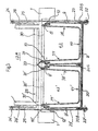
- FIG. 3 is a vertical transverse section view taken through the section line 3 - 3 of FIG. 2 showing the arrangement of dirt containers in the use position.
- FIG. 1 A floor-cleaning machine illustrated in FIG. 1 .
- the machine 2 is of a known type of construction and has a chassis 1 or main frame, on which there are mounted rear wheels 4 and 5 and a front wheel 6 .
- the front wheel 6 is driven and steerable by the operator.
- On the chassis there is a forward operators station 2 which includes a driver's seat and the controls necessary for operation of the floor-cleaning machine.
- the floor-cleaning machine has a rotary-driven roller or cylindrical brush 7 , which, in operation, contacts the floor to be cleaned, and picks up dust, dirt and other debris in an overhead motion.
- the dirt is transported by the brush 7 and an air stream generated by an impeller (not shown) which creates suction to the rear of the brush.
- the dirt is carried via a dirt transfer duct 12 A through dirt delivery openings in a wall of the outer casing, and thence into inlet openings of dirt containers 9 , 9 ′, to be described.
- the air stream with entrained dirt and dust travels along the dirt transfer duct 12 A. Heavier materials fall under gravity into the containers and the air and lighter materials pass through a conventional filter located above the container inlet openings for filtering the solids. The clean, filtered air then exits into the atmosphere.
- FIGS. 2 and 3 the rear section of the floor-cleaning machine 2 corresponds to FIG. 1 in a simplified or schematic form.
- the outer housing or casing and the filter are not shown for simplicity.
- the dirt that is picked up from the floor by cylindrical brush 7 is carried to a did transfer duct 112 A in communication with dirt delivery openings 30 , 30 ′ (indicated in FIG. 3 ) formed in a rear wall of the casing, and hence strong.
- the dirt then drops through container inlet openings 8 , 8 ′ for carrying and transporting recovered materials to first and second dirt containers 9 , 9 ′.
- Dust and lighter materials are carried along by the air stream and removed from the air stream by a conventional filter system (located above the dirt delivery openings 30 , 30 ′) before the air is returned to the atmosphere, as is conventional.
- left and right refer to the left and right side of an operator facing the forward direction of the machine (that is, to the left in FIG. 1 ).
- longitudinal refers to the fore-to-aft direction of the machine, that is, the direction of movement of the machine, and “transverse” refers to the lateral or side-to-side direction.
- Dirt containers 9 , 9 ′ are aligned side-by-side in the transverse direction.
- the containers 9 , 9 ′ are supported by a carrier frame 20 which is configured such that the dirt containers are reliably supported and positioned by their outer walls and the peripheral area of the bottom of the containers; and the center area of the carrier frame, located beneath the containers, is open.
- the positioning of dirt containers 9 , 9 ′ is achieved in the longitudinal direction of the floor-cleaning machine by transverse recesses (such as that designated 9 B for container 9 ′) formed in the rear of the bottom wall 9 A of the dirt container 9 ′, as illustrated in FIG. 2 .
- the recess 9 B is received on a ridged cross bar 20 A of carrier frame 20 .
- the containers 9 , 9 ′ are positioned and secured to the floor-cleaning machine when the carrier frame is raised to the use or sealed position seen in FIG. 2A .
- dirt containers 9 , 9 ′ are positioned by vertical guides or flanges 20 B on the sides and 20 C in the center that are part of, and extend above the carrier frame 20 (see FIG. 3 ) and provide seats to secure the containers in place laterally.
- Each dirt container is located for access at the rear of the machine, but could be located at the front as well.
- Each dirt container includes first and second side walls 38 , 38 ′ and 39 , 39 ′, a bottom 40 , 40 ′, an upright exterior wall 41 , 41 ′ (which is a rear wall in the illustrated embodiment) and an inner wall 42 , 42 ′ (which is a forward wall in the illustrated embodiment).
- An operating lever 25 includes a transverse handle (see 25 A in FIG. 1 ), which, when actuated, operates both left and right side connecting rods 23 .
- the right side operating lever 25 In the position seen in FIG. 2 , the right side operating lever 25 is seen in the lowered or container access position.
- the left side operating linkage is similar to the right side.
- Sealing rings or gaskets 31 are secured to the bottom of the casing wall in which the dirt delivery openings are formed, and the seals encompass completely these openings.
- Carrier frame 20 is pivoted at its front to the main frame by pivot pin 21 for pivoting about a transverse horizontal axis.
- connecting rods 23 , 23 ′ are pivotally connected at lower ends by pivot pins 22 , 22 ′.
- the upper ends of connecting rods 23 , 23 ′ are pivotally connected by pins 24 , 24 ′ to an operating lever 25 which is pivotally mounted to the chassis 1 by left and right pins, one of which is seen at 26 .
- a corresponding lever is mounted on the left side.
- the Operator can thus conveniently and easily maneuver the carrier frame 20 between the raised operating position illustrated in FIGS. 1 , 2 A and 3 , and the lowered, or access position illustrated in FIG. 2 , and vice versa.
- Dirt containers 9 , 9 ′ are of similar construction, and therefore only dirt pick-up container 9 need be described for a complete understanding of the Invention.
- Dirt container 9 is a double-walled construction having inner and outer walls, and is preferably manufactured by a conventional rotational molding process.
- the above-mentioned transverse rear recess 98 forms a receptacle for ridged cross bar 20 A of the carrier frame 20 .
- a peripheral recess arranged to receive a handle 10 pivotally mounted to the container by connecting pin 11 .
- the pivoting connection of the handle 10 locates the pivot axis above the center of gravity of dirt container 9 when filled with the same material such that it can be supported by handle 10 , in the manner of a bucket. That is, when a container is removed and held by its handle, the container opening rotates such that the inlet opening 8 , which is inclined upwardly and rearwardly in the use position ( FIG. 2A ) is generally horizontal for transport to avoid spilling.
- the outer portion of the upper peripheral area is recessed to receive the handle 10 such that the handle, when folded, is within this recessed area 12 and hence within an upper extension of the adjacent outward surface of the dirt container, i.e. it does not protrude above the top edge nor laterally beyond the side of the outer wall of the double-wall container, as seen in FIG. 3 .
- the extension of the recess 12 forwardly past connecting pivot pins 11 provides for unobstructed pivoting of the U-shaped handle 10 .
- the recess 12 when viewed from the top, the recess 12 also has a U-shape to conform: to the shape of the bail handle 10 which has left and right straight legs, the distal ends of which are pivotally connected to the bucket within the recess (see 11 in FIG. 2 ).
- a central upper recessed handle or finger grip 13 In the upper area of the outer rear (or exterior) wall of dirt container 9 , beneath the handle recess, there is a central upper recessed handle or finger grip 13 . By gripping this recess, the operator can readily remove or insert the dirt container when the carrier frame is lowered to the access position.
- the locating recess 9 B located in the bottom wall of dirt container 9 may be used as a second finger recess for pivoting the container being held in the other hand by handle 10 for emptying the contents.
- the inlet aperture of the dirt container 9 forms a plane which is inclined in the use position extending from a forward position, upwardly and rearwardly at an included angle of approximately 35° with the horizontal, and preferably in the range of 30°-40° This angle may approximate an angle of repose for light, smaller particulate material such as fine sand, to permit the containers to be filled without spilling over in the use position.
- dirt containers 9 , 9 ′ can readily be inserted into the carrier frame 20 in the lower access position, in accordance with FIG. 2 , and the containers can then be removed.
- an access gap is provided above the container through which the operator can place any dirt picked up with a dustpan, or other items, into the dirt containers.
- the dirt container to be taken out for emptying can be handled by the operator by the handle, in the manner of a bucket, and then emptied without the user having to be concerned about being soiled from gripping the handle and/or by contact with the outside of the dirt container. Furthermore, in operation, no dirt coming through inlet apertures 30 , 30 ′ will be deposited on carrier frame 20 which has open centers beneath the containers so that it need not be cleaned periodically, as required by some prior machines.
- the dirt containers are located at the rear of the machine, and are accessible from the rear.
- the containers could be located at the front of the machine so that the larger wall of each container is an exterior wall and the smaller will is an interior wall, for example.
- the brush is designed for overhead dirt delivery, and could be a “dust pan” or underhand delivery of dirt, to the forward end, for example. It is, therefore, intended that all such modifications and substitutions be covered as they are embraced within the spirit and scope of the appended claims.
Abstract
Description
Claims (8)
Priority Applications (1)
| Application Number | Priority Date | Filing Date | Title |
|---|---|---|---|
| US12/236,703 US8038030B2 (en) | 2003-05-30 | 2008-09-24 | Floor cleaning machine |
Applications Claiming Priority (4)
| Application Number | Priority Date | Filing Date | Title |
|---|---|---|---|
| DE10324826.9 | 2003-05-30 | ||
| DE10324826A DE10324826A1 (en) | 2003-05-30 | 2003-05-30 | Floor cleaning machine |
| US10/854,459 US7555801B2 (en) | 2003-05-30 | 2004-05-26 | Floor cleaning machine |
| US12/236,703 US8038030B2 (en) | 2003-05-30 | 2008-09-24 | Floor cleaning machine |
Related Parent Applications (1)
| Application Number | Title | Priority Date | Filing Date |
|---|---|---|---|
| US10/854,459 Continuation US7555801B2 (en) | 2003-05-30 | 2004-05-26 | Floor cleaning machine |
Publications (2)
| Publication Number | Publication Date |
|---|---|
| US20090045208A1 US20090045208A1 (en) | 2009-02-19 |
| US8038030B2 true US8038030B2 (en) | 2011-10-18 |
Family
ID=33103670
Family Applications (2)
| Application Number | Title | Priority Date | Filing Date |
|---|---|---|---|
| US10/854,459 Expired - Fee Related US7555801B2 (en) | 2003-05-30 | 2004-05-26 | Floor cleaning machine |
| US12/236,703 Expired - Fee Related US8038030B2 (en) | 2003-05-30 | 2008-09-24 | Floor cleaning machine |
Family Applications Before (1)
| Application Number | Title | Priority Date | Filing Date |
|---|---|---|---|
| US10/854,459 Expired - Fee Related US7555801B2 (en) | 2003-05-30 | 2004-05-26 | Floor cleaning machine |
Country Status (3)
| Country | Link |
|---|---|
| US (2) | US7555801B2 (en) |
| EP (1) | EP1481625B1 (en) |
| DE (2) | DE10324826A1 (en) |
Families Citing this family (17)
| Publication number | Priority date | Publication date | Assignee | Title |
|---|---|---|---|---|
| US20040226584A1 (en) | 2003-05-14 | 2004-11-18 | Michael Guest | Multifunctional surface cleaning machine and method of using the same |
| US20120096671A1 (en) | 2010-10-26 | 2012-04-26 | Karcher North America, Inc. | Floor cleaning apparatus employing a combined sweeper and vaccum assembly |
| US8302240B2 (en) | 2009-07-29 | 2012-11-06 | Karcher North America, Inc. | Selectively adjustable steering mechanism for use on a floor cleaning machine |
| US7533435B2 (en) | 2003-05-14 | 2009-05-19 | Karcher North America, Inc. | Floor treatment apparatus |
| DE10324825B4 (en) * | 2003-05-30 | 2010-06-24 | Hako-Werke Gmbh | Floor cleaning machine |
| DE10324826A1 (en) * | 2003-05-30 | 2004-12-16 | Hako-Werke Gmbh | Floor cleaning machine |
| US20080172809A1 (en) * | 2006-11-01 | 2008-07-24 | Park Sung K | Pickup cleaning device with static electric bar/roller |
| US8774970B2 (en) * | 2009-06-11 | 2014-07-08 | S.C. Johnson & Son, Inc. | Trainable multi-mode floor cleaning device |
| EP2377446B1 (en) * | 2010-04-13 | 2013-12-18 | Hako GmbH | Floor cleaning machine |
| USD654234S1 (en) | 2010-12-08 | 2012-02-14 | Karcher North America, Inc. | Vacuum bag |
| US8978190B2 (en) | 2011-06-28 | 2015-03-17 | Karcher North America, Inc. | Removable pad for interconnection to a high-speed driver system |
| USD693529S1 (en) | 2012-09-10 | 2013-11-12 | Karcher North America, Inc. | Floor cleaning device |
| CN105951645B (en) * | 2016-06-29 | 2017-06-09 | 安徽爱瑞特环保科技股份有限公司 | The totally-enclosed pure electric four-wheeled forerunner's sweeping machine of drive type |
| CN106214062A (en) * | 2016-08-19 | 2016-12-14 | 苏州凯丽达电器有限公司 | A kind of trolley type company uses vacuum cleaner |
| USD907868S1 (en) | 2019-01-24 | 2021-01-12 | Karcher North America, Inc. | Floor cleaner |
| CN110820646B (en) * | 2019-11-14 | 2021-11-19 | 刘尧杰 | Wild type sweeper |
| CN113859721B (en) * | 2021-09-30 | 2023-01-17 | 李健 | Replacement device is accomodate to sweeping blanket of airport road surface motor sweeper |
Citations (7)
| Publication number | Priority date | Publication date | Assignee | Title |
|---|---|---|---|---|
| US1399634A (en) | 1919-04-11 | 1921-12-06 | Lund Charles Walter | Street-sweeping brush |
| US5090587A (en) * | 1991-02-19 | 1992-02-25 | Brown Randolph K | Apparatus for storing recyclable waste |
| US5194077A (en) | 1990-03-20 | 1993-03-16 | Clarke Industries, Inc. | Dual chamber filter assembly with shaker |
| US5224617A (en) * | 1990-10-02 | 1993-07-06 | Ipl, Inc. | Tamper evident container |
| US5690247A (en) * | 1996-10-25 | 1997-11-25 | Boover; Richard C. | Wastebasket for removing and retaining a trash can liner |
| US6494341B2 (en) * | 1999-04-08 | 2002-12-17 | Ropak Corporation | Container handle and related methods |
| US7555801B2 (en) * | 2003-05-30 | 2009-07-07 | Hako-Werke Gmbh | Floor cleaning machine |
Family Cites Families (13)
| Publication number | Priority date | Publication date | Assignee | Title |
|---|---|---|---|---|
| DE3225338A1 (en) * | 1982-07-07 | 1984-01-12 | Xaver 8870 Günzburg Mengele | Floor-sweeping machine |
| US4580313A (en) * | 1983-09-12 | 1986-04-08 | Tennant Company | Walk behind floor maintenance machine |
| US4644532A (en) * | 1985-06-10 | 1987-02-17 | International Business Machines Corporation | Automatic update of topology in a hybrid network |
| US4939726A (en) * | 1989-07-18 | 1990-07-03 | Metricom, Inc. | Method for routing packets in a packet communication network |
| US5311585A (en) * | 1992-04-14 | 1994-05-10 | At&T Bell Laboratories | Carrier proportioned routing |
| GB2287418B (en) * | 1994-03-08 | 1996-09-04 | Applied Sweepers Ltd | Suction sweeping machine |
| US6061505A (en) * | 1994-07-22 | 2000-05-09 | Nortel Networks Corporation | Apparatus and method for providing topology information about a network |
| US5732086A (en) * | 1995-09-21 | 1998-03-24 | International Business Machines Corporation | System and method for determining the topology of a reconfigurable multi-nodal network |
| GB2306345B (en) * | 1995-10-20 | 1999-06-23 | Applied Sweepers Ltd | Suction sweeping machine |
| JP2985940B2 (en) * | 1996-11-08 | 1999-12-06 | 日本電気株式会社 | Failure recovery device |
| US5986782A (en) * | 1997-05-29 | 1999-11-16 | Ciena Corporation | Signal-to-noise monitoring in WDM optical communication systems |
| DE29814661U1 (en) * | 1998-08-14 | 1998-12-03 | Focks Hubert | Movable device with lowerable tool |
| US6529301B1 (en) * | 1999-07-29 | 2003-03-04 | Nortel Networks Limited | Optical switch and protocols for use therewith |
-
2003
- 2003-05-30 DE DE10324826A patent/DE10324826A1/en not_active Withdrawn
-
2004
- 2004-05-26 US US10/854,459 patent/US7555801B2/en not_active Expired - Fee Related
- 2004-05-27 DE DE502004010254T patent/DE502004010254D1/en active Active
- 2004-05-27 EP EP04012582A patent/EP1481625B1/en not_active Expired - Fee Related
-
2008
- 2008-09-24 US US12/236,703 patent/US8038030B2/en not_active Expired - Fee Related
Patent Citations (7)
| Publication number | Priority date | Publication date | Assignee | Title |
|---|---|---|---|---|
| US1399634A (en) | 1919-04-11 | 1921-12-06 | Lund Charles Walter | Street-sweeping brush |
| US5194077A (en) | 1990-03-20 | 1993-03-16 | Clarke Industries, Inc. | Dual chamber filter assembly with shaker |
| US5224617A (en) * | 1990-10-02 | 1993-07-06 | Ipl, Inc. | Tamper evident container |
| US5090587A (en) * | 1991-02-19 | 1992-02-25 | Brown Randolph K | Apparatus for storing recyclable waste |
| US5690247A (en) * | 1996-10-25 | 1997-11-25 | Boover; Richard C. | Wastebasket for removing and retaining a trash can liner |
| US6494341B2 (en) * | 1999-04-08 | 2002-12-17 | Ropak Corporation | Container handle and related methods |
| US7555801B2 (en) * | 2003-05-30 | 2009-07-07 | Hako-Werke Gmbh | Floor cleaning machine |
Also Published As
| Publication number | Publication date |
|---|---|
| US7555801B2 (en) | 2009-07-07 |
| US20040255413A1 (en) | 2004-12-23 |
| EP1481625A2 (en) | 2004-12-01 |
| DE502004010254D1 (en) | 2009-12-03 |
| US20090045208A1 (en) | 2009-02-19 |
| EP1481625A3 (en) | 2008-09-24 |
| EP1481625B1 (en) | 2009-10-21 |
| DE10324826A1 (en) | 2004-12-16 |
Similar Documents
| Publication | Publication Date | Title |
|---|---|---|
| US8038030B2 (en) | Floor cleaning machine | |
| EP0135787B1 (en) | Walk behind floor maintenance machine | |
| EP1887918B1 (en) | Floor sweeping and scrubbing machine | |
| NZ233477A (en) | Grass catcher for rideable mower with pivoting cover and clippings container | |
| US6082574A (en) | Collection apparatus | |
| JPH07215407A (en) | Storage container lid with scoop | |
| US20210127917A1 (en) | Cleaning device | |
| US20020138939A1 (en) | Litter vacuum | |
| US20080086836A1 (en) | Vacuum cleaner with large debris receptacle | |
| US6554334B2 (en) | Apparatus and method for the collection and disposal of waste materials | |
| US5252020A (en) | Waste segregating collection apparatus | |
| US5477578A (en) | Machines for scrubbing or finishing floor surfaces | |
| US808739A (en) | Street-sweeper's cart. | |
| US4503661A (en) | Leaf and lawn debris lift and bagger | |
| US3717901A (en) | Refuse hoppers | |
| JP3299847B2 (en) | Self-propelled vacuum cleaner | |
| WO1995010215A1 (en) | Improvements in and relating to vacuum cleaning apparatus | |
| EP0857031B1 (en) | Suction sweeping machine | |
| CN110396972B (en) | Waste collecting device | |
| CA3114997C (en) | A steerable mobile cart to deposit yard waste directly from a leaf vacuum into a disposable yard waste bag | |
| CN219895595U (en) | Cleaning device | |
| JPH09315501A (en) | Housing tool | |
| US20240122131A1 (en) | Steerable mobile cart to deposit yard waste directly from a leaf vacuum into a disposable yard waste bag | |
| WO2020234522A1 (en) | Device for using a product for absorbing spilled fluids, including recycling of said product | |
| JP2023003778A (en) | Cleaning device |
Legal Events
| Date | Code | Title | Description |
|---|---|---|---|
| AS | Assignment |
Owner name: HAKO-WERKE GMBH, GERMANY Free format text: ASSIGNMENT OF ASSIGNORS INTEREST;ASSIGNORS:PETERS, MARCO;KATENHUSEN, HEINRICH;REEL/FRAME:021578/0684 Effective date: 20040617 |
|
| ZAAA | Notice of allowance and fees due |
Free format text: ORIGINAL CODE: NOA |
|
| ZAAB | Notice of allowance mailed |
Free format text: ORIGINAL CODE: MN/=. |
|
| STCF | Information on status: patent grant |
Free format text: PATENTED CASE |
|
| FPAY | Fee payment |
Year of fee payment: 4 |
|
| FEPP | Fee payment procedure |
Free format text: MAINTENANCE FEE REMINDER MAILED (ORIGINAL EVENT CODE: REM.); ENTITY STATUS OF PATENT OWNER: LARGE ENTITY |
|
| FEPP | Fee payment procedure |
Free format text: 7.5 YR SURCHARGE - LATE PMT W/IN 6 MO, LARGE ENTITY (ORIGINAL EVENT CODE: M1555); ENTITY STATUS OF PATENT OWNER: LARGE ENTITY |
|
| MAFP | Maintenance fee payment |
Free format text: PAYMENT OF MAINTENANCE FEE, 8TH YEAR, LARGE ENTITY (ORIGINAL EVENT CODE: M1552); ENTITY STATUS OF PATENT OWNER: LARGE ENTITY Year of fee payment: 8 |
|
| FEPP | Fee payment procedure |
Free format text: MAINTENANCE FEE REMINDER MAILED (ORIGINAL EVENT CODE: REM.); ENTITY STATUS OF PATENT OWNER: LARGE ENTITY |
|
| LAPS | Lapse for failure to pay maintenance fees |
Free format text: PATENT EXPIRED FOR FAILURE TO PAY MAINTENANCE FEES (ORIGINAL EVENT CODE: EXP.); ENTITY STATUS OF PATENT OWNER: LARGE ENTITY |
|
| STCH | Information on status: patent discontinuation |
Free format text: PATENT EXPIRED DUE TO NONPAYMENT OF MAINTENANCE FEES UNDER 37 CFR 1.362 |
|
| FP | Lapsed due to failure to pay maintenance fee |
Effective date: 20231018 |