EP3967573B1 - Elektrohydraulisches drive-by-wire-lenksystem und hybrides steuerungsverfahren für doppelwicklungsmotor - Google Patents
Elektrohydraulisches drive-by-wire-lenksystem und hybrides steuerungsverfahren für doppelwicklungsmotor Download PDFInfo
- Publication number
- EP3967573B1 EP3967573B1 EP20850637.8A EP20850637A EP3967573B1 EP 3967573 B1 EP3967573 B1 EP 3967573B1 EP 20850637 A EP20850637 A EP 20850637A EP 3967573 B1 EP3967573 B1 EP 3967573B1
- Authority
- EP
- European Patent Office
- Prior art keywords
- steering
- motor
- signal
- work
- winding
- Prior art date
- Legal status (The legal status is an assumption and is not a legal conclusion. Google has not performed a legal analysis and makes no representation as to the accuracy of the status listed.)
- Active
Links
Images


Classifications
-
- B—PERFORMING OPERATIONS; TRANSPORTING
- B62—LAND VEHICLES FOR TRAVELLING OTHERWISE THAN ON RAILS
- B62D—MOTOR VEHICLES; TRAILERS
- B62D5/00—Power-assisted or power-driven steering
- B62D5/04—Power-assisted or power-driven steering electrical, e.g. using an electric servo-motor connected to, or forming part of, the steering gear
- B62D5/0457—Power-assisted or power-driven steering electrical, e.g. using an electric servo-motor connected to, or forming part of, the steering gear characterised by control features of the drive means as such
- B62D5/046—Controlling the motor
- B62D5/0463—Controlling the motor calculating assisting torque from the motor based on driver input
-
- B—PERFORMING OPERATIONS; TRANSPORTING
- B62—LAND VEHICLES FOR TRAVELLING OTHERWISE THAN ON RAILS
- B62D—MOTOR VEHICLES; TRAILERS
- B62D5/00—Power-assisted or power-driven steering
- B62D5/04—Power-assisted or power-driven steering electrical, e.g. using an electric servo-motor connected to, or forming part of, the steering gear
- B62D5/0457—Power-assisted or power-driven steering electrical, e.g. using an electric servo-motor connected to, or forming part of, the steering gear characterised by control features of the drive means as such
- B62D5/046—Controlling the motor
-
- B—PERFORMING OPERATIONS; TRANSPORTING
- B62—LAND VEHICLES FOR TRAVELLING OTHERWISE THAN ON RAILS
- B62D—MOTOR VEHICLES; TRAILERS
- B62D5/00—Power-assisted or power-driven steering
- B62D5/04—Power-assisted or power-driven steering electrical, e.g. using an electric servo-motor connected to, or forming part of, the steering gear
-
- B—PERFORMING OPERATIONS; TRANSPORTING
- B62—LAND VEHICLES FOR TRAVELLING OTHERWISE THAN ON RAILS
- B62D—MOTOR VEHICLES; TRAILERS
- B62D15/00—Steering not otherwise provided for
- B62D15/02—Steering position indicators ; Steering position determination; Steering aids
-
- B—PERFORMING OPERATIONS; TRANSPORTING
- B62—LAND VEHICLES FOR TRAVELLING OTHERWISE THAN ON RAILS
- B62D—MOTOR VEHICLES; TRAILERS
- B62D15/00—Steering not otherwise provided for
- B62D15/02—Steering position indicators ; Steering position determination; Steering aids
- B62D15/021—Determination of steering angle
- B62D15/0215—Determination of steering angle by measuring on the steering column
-
- B—PERFORMING OPERATIONS; TRANSPORTING
- B62—LAND VEHICLES FOR TRAVELLING OTHERWISE THAN ON RAILS
- B62D—MOTOR VEHICLES; TRAILERS
- B62D15/00—Steering not otherwise provided for
- B62D15/02—Steering position indicators ; Steering position determination; Steering aids
- B62D15/021—Determination of steering angle
- B62D15/0235—Determination of steering angle by measuring or deriving directly at the electric power steering motor
-
- B—PERFORMING OPERATIONS; TRANSPORTING
- B62—LAND VEHICLES FOR TRAVELLING OTHERWISE THAN ON RAILS
- B62D—MOTOR VEHICLES; TRAILERS
- B62D5/00—Power-assisted or power-driven steering
-
- B—PERFORMING OPERATIONS; TRANSPORTING
- B62—LAND VEHICLES FOR TRAVELLING OTHERWISE THAN ON RAILS
- B62D—MOTOR VEHICLES; TRAILERS
- B62D5/00—Power-assisted or power-driven steering
- B62D5/001—Mechanical components or aspects of steer-by-wire systems, not otherwise provided for in this maingroup
- B62D5/003—Backup systems, e.g. for manual steering
-
- B—PERFORMING OPERATIONS; TRANSPORTING
- B62—LAND VEHICLES FOR TRAVELLING OTHERWISE THAN ON RAILS
- B62D—MOTOR VEHICLES; TRAILERS
- B62D5/00—Power-assisted or power-driven steering
- B62D5/04—Power-assisted or power-driven steering electrical, e.g. using an electric servo-motor connected to, or forming part of, the steering gear
- B62D5/0457—Power-assisted or power-driven steering electrical, e.g. using an electric servo-motor connected to, or forming part of, the steering gear characterised by control features of the drive means as such
- B62D5/0481—Power-assisted or power-driven steering electrical, e.g. using an electric servo-motor connected to, or forming part of, the steering gear characterised by control features of the drive means as such monitoring the steering system, e.g. failures
-
- B—PERFORMING OPERATIONS; TRANSPORTING
- B62—LAND VEHICLES FOR TRAVELLING OTHERWISE THAN ON RAILS
- B62D—MOTOR VEHICLES; TRAILERS
- B62D5/00—Power-assisted or power-driven steering
- B62D5/06—Power-assisted or power-driven steering fluid, i.e. using a pressurised fluid for most or all the force required for steering a vehicle
- B62D5/062—Details, component parts
- B62D5/064—Pump driven independently from vehicle engine, e.g. electric driven pump
-
- B—PERFORMING OPERATIONS; TRANSPORTING
- B62—LAND VEHICLES FOR TRAVELLING OTHERWISE THAN ON RAILS
- B62D—MOTOR VEHICLES; TRAILERS
- B62D5/00—Power-assisted or power-driven steering
- B62D5/06—Power-assisted or power-driven steering fluid, i.e. using a pressurised fluid for most or all the force required for steering a vehicle
- B62D5/09—Power-assisted or power-driven steering fluid, i.e. using a pressurised fluid for most or all the force required for steering a vehicle characterised by means for actuating valves
-
- B—PERFORMING OPERATIONS; TRANSPORTING
- B62—LAND VEHICLES FOR TRAVELLING OTHERWISE THAN ON RAILS
- B62D—MOTOR VEHICLES; TRAILERS
- B62D5/00—Power-assisted or power-driven steering
- B62D5/06—Power-assisted or power-driven steering fluid, i.e. using a pressurised fluid for most or all the force required for steering a vehicle
- B62D5/30—Safety devices, e.g. alternate emergency power supply or transmission means to ensure steering upon failure of the primary steering means
-
- B—PERFORMING OPERATIONS; TRANSPORTING
- B62—LAND VEHICLES FOR TRAVELLING OTHERWISE THAN ON RAILS
- B62D—MOTOR VEHICLES; TRAILERS
- B62D6/00—Arrangements for automatically controlling steering depending on driving conditions sensed and responded to, e.g. control circuits
-
- B—PERFORMING OPERATIONS; TRANSPORTING
- B62—LAND VEHICLES FOR TRAVELLING OTHERWISE THAN ON RAILS
- B62D—MOTOR VEHICLES; TRAILERS
- B62D5/00—Power-assisted or power-driven steering
- B62D5/04—Power-assisted or power-driven steering electrical, e.g. using an electric servo-motor connected to, or forming part of, the steering gear
- B62D5/0403—Power-assisted or power-driven steering electrical, e.g. using an electric servo-motor connected to, or forming part of, the steering gear characterised by constructional features, e.g. common housing for motor and gear box
Definitions
- the present invention relates to the technical field of vehicle steering systems, and more particularly relates to a drive-by-wire electro-hydraulic steering system based on a double-winding motor as specified in any of claims 1-7 and a hybrid control method as specified in claims 8-10.
- the steering system uses the drive-by-wire hydraulic power under the normal condition, and uses the electro-hydraulic power when the drive-by-wire fault occurs.
- the problem that the electro-hydraulic power-assisted steering system cannot often work in a rotating speed range corresponding to high efficiency is solved.
- the above-mentioned electro-hydraulic power-assisted steering has the problems of great energy consumption and poor operation stability under the high-speed work condition.
- a China invention patent with the application number of CN201811112412.9 discloses a dual-power-assisted steering system integrating electro-hydraulic power-assisted torque and drive-by-wire motor power-assisted torque, so that great steering torque can be provided, and at the same time, the operation stability of the steering system under the high-speed work condition is ensured.
- a drive-by-wire motor only has one group of windings. When the drive-by-wire motor fails, the comprehensive performance of the steering system is greatly reduced, and the problem of low reliability still exists.
- CN 109774786 A relates to a multi-mode power-assisted steering system based on drive-by-wire steering and a control method of the system.
- an objective of the present invention is to provide a drive-by-wire electro-hydraulic steering system based on a double-winding motor as specified in any of claims 1-7 and a hybrid control method as specified in any of claims 8-10, so as to realize application of drive-by-wire steering to big vehicles such as commercial vehicles, improve the operation stability of big vehicles such as commercial vehicles under high-speed work conditions, reduce energy consumption of the steering system, and improve the reliability of the steering system.
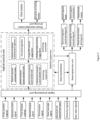
- a drive-by-wire electro-hydraulic steering system based on a double-winding motor provided by the present invention includes a steering wheel, a steering column assembly, a road sense assembly, an electro-hydraulic power-assisted module, a double-winding motor power-assisted module, a steering control unit, an electromagnetic clutch, a steering tie rod, a steering trapezoid and steering wheels.
- the steering wheel is connected with the steering column assembly.
- the steering column assembly includes a first steering column, a first torque sensor, a steering angle sensor, a second steering column, a ball screw and a displacement sensor.
- the first torque sensor and the steering angle sensor are respectively and fixedly arranged on the first steering column.
- the second steering column is connected to a screw nut of the ball screw. Two ends of a screw of the ball screw are axially and fixedly connected with a coaxial line of the steering tie rod.
- the displacement sensor is fixedly arranged on the ball screw.
- the first steering column and the second steering column are connected through the electromagnetic clutch. When the electromagnetic clutch is in a disengagement state, acting force input from the steering wheel acts on the road sense assembly through the first steering column. When the electromagnetic clutch is in an engagement state, acting force input from the steering wheel is converted into displacement of the steering tie rod through the first steering column, the electromagnetic clutch, the second steering column and the ball screw.
- the road sense assembly includes a road sense motor, a second torque sensor, and a worm and gear.
- An output end of the road sense motor is connected with a gear end of the worm and gear through the second torque sensor.
- a worm end of the worm and gear is fixed onto the first steering column. Torque output from the road sense motor sequentially passes through the worm and gear and the first steering column to be transmitted to the steering wheel for forming a steering road sense.
- the electro-hydraulic power-assisted module includes an oil tank, a hydraulic pump, a first motor, an electromagnetic reversing valve, a hydraulic cylinder, a piston, a piston rod, and a third torque sensor.
- the piston rod is positioned in the hydraulic cylinder.
- the piston is fixedly arranged on the piston rod.
- Two ends of the piston rod are axially and fixedly connected with the coaxial line of the steering tie rod.
- the third torque sensor is arranged at an output end of the first motor. Hydraulic oil sequentially flows to the electromagnetic reversing valve from the oil tank and the hydraulic pump under the effect of the first motor.
- the hydraulic oil flows to two sides of the piston inside the hydraulic cylinder to generate a pressure difference at the two sides of the piston, so that axial acting force is generated on the piston rod.
- the piston rod performs axial displacement movement under the effect of the axial force, and the axial displacement movement is transmitted to the steering tie rod to be converted into displacement movement of the steering tie rod.
- the double-winding motor module includes a relay control unit, a double-winding motor, a first current sensor, a second current sensor and a deceleration mechanism.
- the relay control unit includes a relay controller, a relay and a power supply unit. An input end of the relay controller is connected with the steering control unit. An output end of the relay controller is connected with the relay. An input end of the power supply unit is connected with the steering control unit. An output end of the power supply unit is connected with the double-winding motor through the relay to supply electricity to the double-winding motor.
- the double-winding motor includes a stator iron core, a rotor assembly, a machine seat, a first set of windings, a second set of windings, and a double-winding motor output shaft.
- the first set of windings includes a phase A winding, a phase B winding and a phase C winding.
- the second set of windings includes a phase a winding, a phase b winding and a phase c winding.
- An input end of the first set of windings is divided into three branches respectively connected with an input end of the phase A winding, an input end of the phase B winding and an input end of the phase C winding.
- An input end of the second set of windings is divided into three branches respectively connected with an input end of the phase a winding, an input end of the phase b winding and an input end of the phase c winding.
- Stator slots are distributed on the stator iron core.
- the same phase of windings of the first set of windings and the second set of windings are staggered for an electric angle of 30° to be embedded and put in different stator slots.
- the stator iron core is fixed onto the machine seat.
- the input end of the first set of windings is connected with the first current sensor.
- the input end of the second set of windings is connected with the second current sensor.
- the rotor assembly includes a rotor iron core and a rotor winding.
- the rotor winding is wound on the rotor iron core.
- the rotor iron core is fixed onto the double-winding motor output shaft.
- the first set of windings and the second set of windings work at the same time to generate a resultant magnetic field to generate an induction current in the rotor winding.
- the induction current drives the rotor iron core to rotate under the effect of the magnetic field.
- the rotor iron core outputs torque through the double-winding motor output shaft.
- the deceleration mechanism includes a pinion, a belt and a gearwheel.
- the pinion is fixed onto the double-winding motor output shaft in the axial direction.
- the belt is connected with the pinion and the gearwheel. Screw threads are formed inside the gearwheel.
- the gearwheel is sleeved over the ball screw in the axial direction.
- the steering control unit includes a main controller and other vehicle state units.
- An input end of the main controller is electrically connected with each sensor, and obtains a first torque signal, a second torque signal, a third torque signal, a first current signal, a second current signal, a steering angle signal, and a steering tie rod displacement signal.
- the other vehicle state units provide a velocity signal and a yaw rate signal of a current vehicle state for the main controller.
- An output end of the main controller is connected with the road sense assembly, the electromagnetic clutch, the first motor, and the relay control unit.
- the electromagnetic clutch includes an armature, a driving shaft, a driven shaft, an electromagnet and a friction sheet group.
- the driving shaft is fixed to the first steering column in the axial direction.
- the driven shaft is fixed to the second steering column in the axial direction.
- the armature is sleeved over the driving shaft, and is able to axially move.
- the electromagnet is fixed onto the driving shaft.
- the friction sheet group is fixed onto the driven shaft.
- the electromagnet is positioned between the armature and the friction sheet group.
- An electromagnetic clutch control signal output by the main controller controls an on-off state of a coil, and further controls engagement and disengagement of the electromagnetic clutch.
- the electromagnetic reversing valve has three work states: a forward loading work state, a reverse loading work state and an unloading work state.
- the first motor drives an oil pump
- the electromagnetic reversing valve controls opening and closing of the valve so as to make the hydraulic oil forwardly flow
- the hydraulic coil flows to the two sides of the piston inside the hydraulic cylinder, and a pressure at the left side of the piston is greater than that at the right side, so that steering power is provided for the vehicle during rightward steering.
- the first motor drives the oil pump, the electromagnetic reversing valve controls opening and closing of the valve so as to make the hydraulic oil reversely flow, the hydraulic oil flows to the two sides of the piston inside the hydraulic cylinder, and the pressure at the right side of the piston is greater than that at the left side, so that steering power is provided for the vehicle during rightward steering.
- the first motor stops working, the hydraulic oil stops flowing to the two sides of the piston inside the hydraulic cylinder, and steering power is unable to be provided.
- the double-winding motor output shaft is arranged parallel to the steering die rod, and is connected onto the ball screw through the deceleration mechanism. Rotation movement of the double-winding motor output shaft is converted into rotation movement of the pinion. The rotation movement of the pinion is converted into rotation movement of the gearwheel through the belt. The rotation movement of the gearwheel is converted into displacement movement of the steering tie rod through the ball screw.
- the steering tie rod, the piston rod and the ball screw are fixedly connected into a whole, displacement of the piston rod and the ball screw is overlapped on the steering die rod, and two ends of the steering tie rod are respectively connected with the steering wheels through the steering trapezoid, so that the displacement movement of the steering tie rod is converted into steering angles of the steering wheels, and vehicle steering action is completed.
- the double-winding motor is a brushless direct current motor.
- first current sensor and the second current sensor are Hall current sensors.
- the main controller includes a signal processing unit, a steering decision unit, a steering database, a hybrid control unit, a power-assisted motor driving unit, a road sense motor driving unit, an electromagnetic reversing valve driving unit and an electromagnetic clutch driving unit.
- the signal processing unit is electrically connected with each sensor and the other vehicle state units to obtain each sensor signal and other vehicle state signals in real time.
- the steering decision unit receives input signals of the signal processing unit, the steering database and the hybrid control unit through a vehicle-mounted communication line.
- the road sense motor driving unit, the electromagnetic reversing valve driving unit and the electromagnetic clutch driving unit receive an input signal of the steering decision unit through the vehicle-mounted communication line, and respectively output a road sense motor control signal, an electromagnetic reversing valve control signal and an electromagnetic clutch control signal.
- the hybrid control unit receives input signals of the signal processing unit and the steering database through the vehicle-mounted communication line.
- the power-assisted motor driving unit receives an input signal of the hybrid control unit through the vehicle-mounted communication line, and respectively outputs a first motor control signal and a double-winding motor control signal to complete steering action control.
- the hybrid control unit includes a switching supervisor, a switching controller, and a stability supervisor.
- the switching supervisor switches the work mode of the steering system according to an input signal of the signal processing unit, simultaneously detects a changing process of all work modes of the steering system, and reduces impact and shock caused by mode switching in the steering control process.
- the switching controller selects a control algorithm corresponding to each work mode of the steering system according to the work modes of the steering system recognized by the switching supervisor.
- the stability supervisor monitors instability characteristic quantities in each work mode and the corresponding control algorithm in real time, recognizes an instability trend, and forcibly limits an output amplitude value.
- the electromagnet includes the coil and a magnet yoke.
- the electromagnetic clutch has two work states: a disengagement work state and an engagement work state.
- the magnet yoke When the coil is not electrified, the magnet yoke is separated from the armature, the friction sheet group does not transmit the torque, the electromagnetic clutch is in the disengagement state, and the torque is not transmitted between the first steering column and the second steering column.
- the magnet yoke is sucked with the armature to tightly press the friction sheet group, the friction sheet group transmits the torque through friction force, the electromagnetic clutch is in the engagement state, and the torque is transmitted between the first steering column and the second steering column.
- a hybrid control method of a drive-by-wire electro-hydraulic steering system based on a double-winding motor provided by the present invention is based on the system, and includes the following steps:
- the steering system has four work modes: an electric power-assisted mode, an electro-hydraulic composite power-assisted mode, an electro-hydraulic power-assisted mode and a mechanical composite power-assisted mode.
- control algorithm corresponding to each work mode of the steering system specifically includes:
- switching the work mode of the steering system by the switching supervisor specifically includes:
- 20 Km/h is used as a medium-low-speed switching point
- 60 Km/h is used as a medium-high-speed switching point
- the work condition with the velocity between 0 Km/h and 20 Km/h is the low-speed work condition
- the work condition with the velocity between 20 Km/h and 60 Km/h is the medium-speed work condition
- the work condition with the velocity higher than 60 Km/h is the high-speed work condition.
- the present invention has the beneficial effects:
- the present invention integrates advantages of electric steering and hydraulic steering in a drive-by-wire steering system.
- the sufficient power-assisted torque can be output.
- the problems that an existing drive-by-wire steering system has low power and is difficult to be applied to big vehicles such as commercial vehicles are solved.
- the steering precision of the steering system is improved.
- the problem of poor operation stability of hydraulic steering under the high-speed work condition is solved.
- a drive-by-wire motor is arranged on the steering tie rod, the mechanical coupling and interference caused by electric power is reduced, and the steering precision of the steering system is further improved.
- the present invention can realize switching among various steering work modes according to the current work condition of the vehicle, and meets the steering requirements under various work conditions. Through mode switching, the hydraulic power-assisted work time can be reduced, and the energy consumption of the steering system is greatly reduced. Additionally, a work mode that two sets of windings of the double-winding motor work at the same time is used, and the motor winding redundancy function is realized. When one set of windings fails, the other set of windings can drive the motor to provide the power-assisted torque. The reliability of the steering system is improved. The vehicle driving safety is enhanced.
- the hybrid control method of the present invention converts a control problem of the steering system under the complicated work condition into a switching coordination problem between multi-mode control and the control algorithm to be solved.
- the switching supervisor and the stability supervisor of the steering control system are built.
- the impact and shock caused by mode switching in the steering control process are reduced.
- the gradual stability and global bounded stability in the work mode switching process are ensured.
- 1 denotes a steering wheel
- 2 denotes a steering angle sensor
- 3 denotes a first torque sensor
- 4 denotes a worm and gear
- 5 denotes a first steering column
- 6 denotes an electromagnetic clutch
- 7 denotes an electromagnetic reversing valve
- 8 denotes a hydraulic pump
- 9 denotes a first motor
- 10 denotes a third torque sensor
- 11 denotes an oil tank
- 12 denotes a steering wheel
- 13 denotes a steering trapezoid
- 14 denotes a piston rod
- 15 denotes a piston
- 16 denotes a hydraulic cylinder
- 17 denotes a steering tie rod
- 18 denotes a second steering column
- 19 denotes a screw nut
- 20 denotes a ball screw
- 21 denotes a displacement sensor
- 22 denotes a deceleration mechanism
- 23 denotes a double-winding motor output shaft
- 24 de
- A denotes a rotating angle signal
- B denotes a first torque signal
- C denotes a second torque signal
- D denotes a third torque signal
- E denotes a first current signal
- F denotes a second current signal
- G denotes a steering tie rod displacement signal
- H denotes a road sense motor control signal
- I denotes a first motor control signal
- J denotes an electromagnetic clutch control signal
- K denotes an electromagnetic reversing valve control signal
- L denotes a double-winding motor control signal
- M denotes a velocity signal
- N denotes a yaw rate signal.
- a drive-by-wire electro-hydraulic steering system based on a double-winding motor includes a steering wheel 1, a steering column assembly, a road sense assembly, an electro-hydraulic power-assisted module, a double-winding motor power-assisted module 28, a steering control unit, an electromagnetic clutch 6, a steering tie rod 17, a steering trapezoid 13 and steering wheels 12.
- the steering wheel 1 is connected with the steering column assembly.
- the steering column assembly includes a first steering column 5, a first torque sensor 3, a steering angle sensor 2, a second steering column 18, a ball screw 20 and a displacement sensor 21.
- the first torque sensor 3 and the steering angle sensor 2 are respectively and fixedly arranged on the first steering column 5.
- the second steering column 18 is connected to a screw nut 19 of the ball screw 20. Two ends of a screw of the ball screw 20 are axially and fixedly connected with a coaxial line of the steering tie rod 17.
- the displacement sensor 21 is fixedly arranged on the ball screw 20.
- the first steering column 5 and the second steering column 18 are connected through the electromagnetic clutch 6.
- the road sense assembly includes a road sense motor 32, a second torque sensor 33, and a worm and gear 4.
- An output end of the road sense motor 32 is connected with a gear end of the worm and gear 32 through the second torque sensor 33.
- a worm end of the worm and gear 4 is fixed onto the first steering column 5. Torque output from the road sense motor 32 sequentially passes through the worm and gear 4 and the first steering column 5 to be transmitted to the steering wheel 1 for forming a steering road sense.
- the electro-hydraulic power-assisted module includes an oil tank 11, a hydraulic pump 8, a first motor 9, an electromagnetic reversing valve 7, a hydraulic cylinder 16, a piston 15, a piston rod 14, and a third torque sensor 10.
- the piston rod 14 is positioned in the hydraulic cylinder 16.
- the piston 15 is fixedly arranged on the piston rod 14.
- Two ends of the piston rod 14 are axially and fixedly connected with the coaxial line of the steering tie rod 17.
- the third torque sensor 10 is arranged at an output end of the first motor 9. Hydraulic oil sequentially flows to the electromagnetic reversing valve 7 from the oil tank 11 and the hydraulic pump 8 under the effect of the first motor 9.
- the hydraulic oil flows to two sides of the piston inside the hydraulic cylinder 16 to generate a pressure difference at the two sides of the piston 15, so that axial acting force is generated on the piston rod 14.
- the piston rod 14 performs axial displacement movement under the effect of the axial force, and the axial displacement movement is transmitted to the steering tie rod 17 to be converted into displacement movement of the steering tie rod.
- the electromagnetic reversing valve 7 has three work states: a forward loading work state, a reverse loading work state and an unloading work state.
- the first motor 9 drives an oil pump
- the electromagnetic reversing valve 7 controls opening and closing of the valve so as to make the hydraulic oil forwardly flow
- the hydraulic coil flows to the two sides of the piston 15 inside the hydraulic cylinder 16, and a pressure at the left side of the piston 15 is greater than that at the right side, so that steering power is provided for the vehicle during rightward steering.
- the first motor 9 drives the oil pump, the electromagnetic reversing valve 7 controls opening and closing of the valve so as to make the hydraulic oil reversely flow, the hydraulic oil flows to the two sides of the piston 15 inside the hydraulic cylinder 16, and the pressure at the right side of the piston 15 is greater than that at the left side, so that steering power is provided for the vehicle during rightward steering.
- the first motor 9 stops working, the hydraulic oil stops flowing to the two sides of the piston 15 inside the hydraulic cylinder, and steering power is unable to be provided.
- the double-winding motor module 28 includes a relay control unit 27, a double-winding motor, a first current sensor 29, a second current sensor 26 and a deceleration mechanism 22.
- the relay control unit 27 includes a relay controller, a relay and a power supply unit. An input end of the relay controller is connected with the steering control unit. An output end of the relay controller is connected with the relay. An input end of the power supply unit is connected with the steering control unit. An output end of the power supply unit is connected with the double-winding motor through the relay to supply electricity to the double-winding motor.
- the double-winding motor is a brushless direct current motor, and includes a stator iron core, a rotor assembly, a machine seat, a first set of windings 24, a second set of windings 25, and a double-winding motor output shaft 23.
- the first set of windings 24 includes a phase A winding, a phase B winding and a phase C winding.
- the second set of windings 25 includes a phase a winding, a phase b winding and a phase c winding.
- An input end of the first set of windings 24 is divided into three branches respectively connected with an input end of the phase A winding, an input end of the phase B winding and an input end of the phase C winding.
- An input end of the second set of windings 25 is divided into three branches respectively connected with an input end of the phase a winding, an input end of the phase b winding and an input end of the phase c winding.
- Stator slots are distributed on the stator iron core.
- the same phase of windings of the first set of windings 24 and the second set of windings 25 are staggered for an electric angle of 30° to be embedded and put in different stator slots.
- the stator iron core is fixed onto the machine seat.
- the input end of the first set of windings 24 is connected with the first current sensor 29.
- the input end of the second set of windings 25 is connected with the second current sensor 26.
- the first current sensor and the second current sensor are both Hall current sensors.
- the rotor assembly includes a rotor iron core and a rotor winding.
- the rotor winding is wound on the rotor iron core.
- the rotor iron core is fixed onto the double-winding motor output shaft.
- the first set of windings and the second set of windings work at the same time to generate a resultant magnetic field to generate an induction current in the rotor winding.
- the induction current drives the rotor iron core to rotate under the effect of the magnetic field.
- the rotor iron core outputs torque through the double-winding motor output shaft.
- the deceleration mechanism 22 includes a pinion, a belt and a gearwheel.
- the pinion is fixed onto the double-winding motor output shaft in the axial direction.
- the belt is connected with the pinion and the gearwheel. Screw threads are formed inside the gearwheel.
- the gearwheel is sleeved over the ball screw 20 in the axial direction.
- the double-winding motor output shaft 23 is arranged parallel to the steering die rod 17, and is connected onto the ball screw 20 through the deceleration mechanism 22. Rotation movement of the double-winding motor output shaft 23 is converted into rotation movement of the pinion. The rotation movement of the pinion is converted into rotation movement of the gearwheel through the belt. The rotation movement of the gearwheel is converted into displacement movement of the steering tie rod through the ball screw.
- the steering tie rod 17, the piston rod 14 and the ball screw 20 are fixedly connected into a whole, displacement of the piston rod 14 and the ball screw 20 is overlapped on the steering die rod, and the two ends of the steering tie rod 17 are respectively connected with the steering wheels through the steering trapezoid, so that the displacement movement of the steering tie rod is converted into steering angles of the steering wheels, and vehicle steering action is completed.
- the steering control unit includes a main controller 31 and other vehicle state units 30.
- An input end of the main controller 31 is electrically connected with each sensor, and obtains a first torque signal B, a second torque signal C, a third torque signal D, a first current signal E, a second current signal F, a steering angle signal A, and a steering tie rod displacement signal G.
- the other vehicle state units 30 provide a velocity signal M and a yaw rate signal N of a current vehicle state for the main controller.
- An output end of the main controller is connected with the road sense assembly, the electromagnetic clutch, the first motor, and the relay control unit.
- the main controller 31 includes a signal processing unit, a steering decision unit, a steering database, a hybrid control unit, a power-assisted motor driving unit, a road sense motor driving unit, an electromagnetic reversing valve driving unit and an electromagnetic clutch driving unit.
- the signal processing unit is electrically connected with each sensor and the other vehicle state units to obtain each sensor signal and other vehicle state signals in real time.
- the steering decision unit receives input signals of the signal processing unit, the steering database and the hybrid control unit through a vehicle-mounted communication line.
- the road sense motor driving unit, the electromagnetic reversing valve driving unit and the electromagnetic clutch driving unit receive an input signal of the steering decision unit through the vehicle-mounted communication line, and respectively output a road sense motor control signal H, an electromagnetic reversing valve control signal K and an electromagnetic clutch control signal J.
- the hybrid control unit receives input signals of the signal processing unit and the steering database through the vehicle-mounted communication line.
- the power-assisted motor driving unit receives an input signal of the hybrid control unit through the vehicle-mounted communication line, and respectively outputs a first motor control signal I and a double-winding motor control signal L to complete steering action control.
- the hybrid control unit includes a switching supervisor, a switching controller, and a stability supervisor.
- the switching supervisor switches the work mode of the steering system according to an input signal of the signal processing unit, simultaneously detects a changing process of all work modes of the steering system, and reduces impact and shock caused by mode switching in the steering control process.
- the switching controller selects a control algorithm corresponding to each work mode of the steering system according to the work modes of the steering system recognized by the switching supervisor.
- the stability supervisor monitors instability characteristic quantities in each work mode and the corresponding control algorithm in real time, recognizes an instability trend, and forcibly limits an output amplitude value.
- the electromagnetic clutch 6 includes an armature, a driving shaft, a driven shaft, an electromagnet and a friction sheet group.
- the driving shaft is fixed to the first steering column in the axial direction.
- the driven shaft is fixed to the second steering column in the axial direction.
- the armature is sleeved over the driving shaft, and is able to axially move.
- the electromagnet is fixed onto the driving shaft.
- the friction sheet group is fixed onto the driven shaft.
- the electromagnet is positioned between the armature and the friction sheet group.
- An electromagnetic clutch control signal output by the main controller controls an on-off state of a coil, and further controls engagement and disengagement of the electromagnetic clutch.
- the electromagnet includes the coil and a magnet yoke.
- the electromagnetic clutch has two work states: a disengagement work state and an engagement work state.
- the magnet yoke When the coil is not electrified, the magnet yoke is separated from the armature, the friction sheet group does not transmit the torque, the electromagnetic clutch is in the disengagement state, and the torque is not transmitted between the first steering column and the second steering column.
- the magnet yoke is sucked with the armature to tightly press the friction sheet group, the friction sheet group transmits the torque through friction force, the electromagnetic clutch is in the engagement state, and the torque can be transmitted between the first steering column and the second steering column.
- a hybrid control method of a drive-by-wire electro-hydraulic steering system based on a double-winding motor provided by the present invention is based on the system, and includes the following steps:
- the steering system has four work modes: an electric power-assisted mode, an electro-hydraulic composite power-assisted mode, an electro-hydraulic power-assisted mode and a mechanical composite power-assisted mode.
- the control algorithm corresponding to each work mode of the steering system specifically includes:
- Switching the work mode of the steering system by the switching supervisor specifically includes:
- 20 Km/h is used as a medium-low-speed switching point
- 60 Km/h is used as a medium-high-speed switching point
- the work condition with the velocity between 0 Km/h and 20 Km/h is the low-speed work condition
- the work condition with the velocity between 20 Km/h and 60 Km/h is the medium-speed work condition
- the work condition with the velocity higher than 60 Km/h is the high-speed work condition.
Landscapes
- Engineering & Computer Science (AREA)
- Chemical & Material Sciences (AREA)
- Combustion & Propulsion (AREA)
- Transportation (AREA)
- Mechanical Engineering (AREA)
- Steering Control In Accordance With Driving Conditions (AREA)
- Power Steering Mechanism (AREA)
Claims (10)
- Drive-by-wire-elektrohydraulisches Lenksystem auf Basis eines Doppelwicklungsmotors, umfassend ein Lenkrad (1), eine Lenksäulenanordnung, eine Straßensensoranordnung, ein elektrohydraulisches Leistungsunterstützungsmodul, ein Leistungsunterstützungsmodul (28) für den Doppelwicklungsmotor, eine Lenksteuereinheit, eine elektromagnetische Kupplung (6), eine Spurstange (17), ein Lenktrapez (13) und Lenkräder (12) umfasst;wobei das Lenkrad (1) mit der Lenksäulenanordnung verbunden ist, und wobei die Lenksäulenanordnung eine erste Lenksäule (5), einen ersten Drehmomentsensor (3), einen Lenkwinkelsensor (2), eine zweite Lenksäule (18), eine Kugelgewindespindel (20) und einen Verschiebungssensor (21) umfasst; wobei der erste Drehmomentsensor (3) und der Lenkwinkelsensor (2) jeweils fest an der ersten Lenksäule (5) angeordnet sind, wobei die zweite Lenksäule (18) mit einer Spindelmutter (19) der Kugelgewindespindel (20) verbunden ist, wobei zwei Enden einer Gewindespindel der Kugelgewindespindel (20) axial und fest mit einer Koaxiallinie der Spurstange (17) verbunden sind, wobei der Verschiebungssensor (21) fest an der Kugelgewindespindel (20) angeordnet ist, und wobei die erste Lenksäule (5) und die zweite Lenksäule (18) über die elektromagnetische Kupplung (6) verbunden sind; wenn sich die elektromagnetische Kupplung (6) in einem Entkoppelungszustand befindet, wirkt die vom Lenkrad (1) eingetragene Wirkkraft durch die erste Lenksäule (5) auf die Straßensensoranordnung; wenn sich die elektromagnetische Kupplung (6) in einem Koppelungszustand befindet, wird die vom Lenkrad (1) eingetragene Wirkkraft durch die erste Lenksäule (5), die elektromagnetische Kupplung (6), die zweite Lenksäule (18) und die Kugelgewindespindel (20) in eine Verschiebung der Spurstange (17) umgewandelt;wobei die Straßensensoranordnung einen Straßensensormotor (32), einen zweiten Drehmomentsensor (33) und ein Schneckengetriebe (4) umfasst; wobei ein Ausgangsende des Straßensensormotors (32) mit einem Zahnradende des Schneckengetriebes (4) über den zweiten Drehmomentsensor (33) verbunden ist, und wobei ein Schneckenende des Schneckengetriebes (4) an der ersten Lenksäule (5) befestigt ist; wobei das Drehmoment, das vom Straßensensormotor (32) ausgegeben wird, führt nacheinander durch das Schneckengetriebe (4) und die erste Lenksäule (5) führt durchläuft und an das Lenkrad (1) übertragen wird, eine Lenk-Straßenwahrnehmung zu erzeugen;wobei das elektrohydraulische Leistungsunterstützungsmodul einen Öltank (11), eine Hydraulikpumpe (8), einen ersten Motor (9), ein elektromagnetisches Umkehrventil (7), einen Hydraulikzylinder, einen Kolben (15), eine Kolbenstange (14) und einen dritten Drehmomentsensor (10) umfasst; wobei die Kolbenstange (14) in den Hydraulikzylinder (16) positioniert ist, wobei der Kolben (15) fest auf der Kolbenstange (14) angeordnet ist, und wobei zwei Enden der Kolbenstange (14) axial und fest mit der Koaxiallinie der Spurstange (17) verbunden sind; wobei der dritte Drehmomentsensor (10) an einem Ausgangsende des ersten Motors (9) angeordnet ist; wobei das Hydrauliköl nacheinander vom Öltank (11) und der Hydraulikpumpe (8) unter Einwirkung des ersten Motors (9) zum elektromagnetischen Umkehrventil (7) fließt, wobei durch unterschiedliche Ventilöffnungsgrade des elektromagnetischen Umkehrventils (7), das Hydrauliköl auf zwei Seiten des Kolbens (15) innerhalb des Hydraulikzylinders (16) fließt, um einen Druckunterschied auf beiden Seiten des Kolbens (15) zu erzeugen, so dass auf der Kolbenstange (14) axiale Wirkkraft erzeugt wird, wobei die Kolbenstange (14) unter Einwirkung der axialen Kraft eine axiale Verschiebungsbewegung durchführt, und wobei die axiale Verschiebungsbewegung an die Spurstange (17) übertragen wird, um in die Verschiebungsbewegung der Spurstange (17) umzuwandeln;wobei das Doppelwicklungsmotormodul eine Relaissteuereinheit (27), einen Doppelwicklungsmotor, einen ersten Stromsensor (29), einen zweiten Stromsensor (26) und einen Verzögerungsmechanismus (22) umfasst;wobei die Relaissteuereinheit (27) eine Relaissteuerung, ein Relais und eine Stromversorgungseinheit umfasst; wobei ein Eingangsende der Relaissteuerung mit der Lenksteuereinheit verbunden ist und ein Ausgangsende der Relaissteuerung mit dem Relais verbunden ist; wobei ein Eingangsende der Stromversorgungseinheit mit der Lenksteuereinheit verbunden ist und ein Ausgangsende der Stromversorgungseinheit über das Relais mit dem Doppelwicklungsmotor verbunden ist, um den Doppelwicklungsmotor mit Strom zu versorgen;wobei der Doppelwicklungsmotor einen Statorkern, eine Rotoranordnung, einen Maschinensitz, eine erste Wicklungsgruppe (24), eine zweite Wicklungsgruppe (25) und eine Ausgangswelle (23) des Doppelwicklungsmotors umfasst;wobei die erste Wicklungsgruppe (24) eine Phasenwicklung A, eine Phasenwicklung B und eine Phasenwicklung C umfasst; wobei die zweite Wicklungsgruppe (25) eine Phasenwicklung A, eine Phasenwicklung B und eine Phasenwicklung C umfasst; wobei ein Eingangsende der ersten Wicklungsgruppe (24) in drei Zweige unterteilt ist, die jeweils mit einem Eingangsende der Phasenwicklung A, einem Eingangsende der Phasenwicklung B und einem Eingangsende der Phasenwicklung C verbunden sind; wobei ein Eingangsende der zweiten Wicklungsgruppe (25) in drei Zweige unterteilt ist, die jeweils mit einem Eingangsende der Phasenwicklung A, einem Eingangsende der Phasenwicklung B und einem Eingangsende der Phasenwicklung C verbunden sind;wobei Statorschlitze auf dem Statorkern verteilt sind, und wobei die gleichen Phasen der Wicklungen der ersten Wicklungsgruppe (24) und der zweiten Wicklungsgruppe (25) sind gestaffelt, um einen elektrischen Winkel von 30° einzubetten und in verschiedene Statorschlitze zu platzieren, und wobei der Statorkern am Maschinensitz befestigt ist; wobei das Eingangsende der ersten Wicklungsgruppe (24) mit dem ersten Stromsensor (29) verbunden ist und das Eingangsende der zweiten Wicklungsgruppe (25) mit dem zweiten Stromsensor (26) verbunden ist;wobei die Rotoranordnung einen Rotorkern und eine Rotorwicklung umfasst; wobei die Rotorwicklung auf den Rotorkern gewickelt und der Rotorkern an der Ausgangswelle (23) des Doppelwicklungsmotors befestigt ist; wobei die erste Wicklungsgruppe (24) und die zweite Wicklungsgruppe (25) gleichzeitig arbeiten, um ein daraus resultierendes Magnetfeld zu erzeugen, um einen Induktionsstrom in der Rotorwicklung zu erzeugen, der den Rotorkern unter der Wirkung des Magnetfelds dreht, und wobei der Rotorkern Drehmoment durch die Ausgangswelle (23) des Doppelwicklungsmotors ausgibt;wobei der Verzögerungsmechanismus (22) ein Ritzel, einen Riemen und ein Zahnrad umfasst; wobei das Ritzel in axialer Richtung an der Ausgangswelle (23) des Doppelwicklungsmotors befestigt ist, wobei der Riemen mit dem Ritzel und dem Zahnrad verbunden ist, wobei innerhalb des Zahnrads Schraubengewinde gebildet sind und das Zahnrad in axialer Richtung über die Kugelgewindespindel (20) verschraubt ist;wobei die Lenksteuereinheit eine Hauptsteuerung (31) und andere Fahrzeugzustandseinheiten (30) umfasst; wobei ein Eingangsende der Hauptsteuerung (31) elektrisch mit jedem Sensor verbunden ist und ein erstes Drehmomentsignal, ein zweites Drehmomentsignal, ein drittes Drehmomentsignal, ein erstes Stromsignal, ein zweites Stromsignal, ein Lenkwinkelsignal und ein Spurstangenverschiebungssignal erhält; wobei die anderen Fahrzeugzustandseinheiten (30) ein Geschwindigkeitssignal und ein Giergeschwindigkeitssignal eines aktuellen Fahrzeugzustands für die Hauptsteuerung (31) bereitstellen; wobei ein Ausgangsende der Hauptsteuerung (31) mit der Straßensensoranordnung, der elektromagnetischen Kupplung (6), dem ersten Motor (9) und der Relaissteuereinheit (27) verbunden ist; undwobei die elektromagnetische Kupplung (6) einen Anker, eine Antriebswelle, eine Abtriebswelle, einen Elektromagnet und eine Reibblechgruppe umfasst; wobei die Antriebswelle in axialer Richtung an der ersten Lenksäule (5) befestigt ist, wobei die Abtriebswelle in axialer Richtung an der zweiten Lenksäule (18) befestigt ist, wobei der Anker auf der Antriebswelle verschiebbar ist und sich axial bewegen kann, wobei der Elektromagnet an der Antriebswelle befestigt ist, wobei die Reibblechgruppe an der Abtriebswelle befestigt ist, und wobei der Elektromagnet zwischen dem Anker und der Reibblechgruppe positioniert ist; und wobei ein von der Hauptsteuerung (31) ausgegebenes elektromagnetisches Kupplungssteuersignal den Ein-/Ausschaltzustand einer Spule steuert und ferner die Koppelung und Entkoppelung der elektromagnetischen Kupplung (6) steuert.
- Drive-by-wire-elektrohydraulische Lenksystem auf Basis eines Doppelwicklungsmotors gemäß Anspruch 1, wobei das elektromagnetische Umkehrventil (7) drei Arbeitszustände aufweist: einen Vorwärtsbeladungszustand, einen Rückbeladungszustand und einen Entladearbeitszustand; wobei während der Vorwärtsbelastung der erste Motor (9) eine Ölpumpe antreibt, wobei das elektromagnetische Umkehrventil (7) das Öffnen und Schließen des Ventils derart steuert, dass das Hydrauliköl nach vorn fließt, wobei die Hydraulikspule auf die beiden Seiten des Kolbens (15) innerhalb des Hydraulikzylinders (16) fließt, und wobei ein Druck auf der linken Seite des Kolbens (15) größer ist als auf der rechten Seite, so dass dem Fahrzeug bei Rechtslenkung Lenkkraft zur Verfügung gestellt wird; wobei während der Rückbeladung der erste Motor (9) die Ölpumpe antreibt, wobei das elektromagnetische Umkehrventil (7) das Öffnen und Schließen des Ventils derart steuert, dass Hydrauliköl in umgekehrter Richtung fließt, wobei das Hydrauliköl auf die beiden Seiten des Kolbens (15) innerhalb des Hydraulikzylinders (16) fließt und der Druck auf der rechten Seite des Kolbens (15) größer ist als auf der linken Seite, so dass dem Fahrzeug bei Rechtslenkung Lenkkraft zur Verfügung gestellt wird; und wobei während des Entladens der erste Motor (9) nicht mehr arbeitet, wobei das Hydrauliköl nicht mehr zu den beiden Seiten des Kolbens (15) innerhalb des Hydraulikzylinders (16) fließt und die Lenkkraft nicht bereitgestellt werden kann.
- Drive-by-wire-elektrohydraulische Lenksystem auf Basis eines Doppelwicklungsmotors gemäß Anspruch 1, wobei die Ausgangswelle (23) des Doppelwicklungsmotors parallel zur Spurstange angeordnet ist und über den Verzögerungsmechanismus (22) an die Kugelgewindespindel (20) angeschlossen ist; und wobei die Drehbewegung der Ausgangswelle (23) des Doppelwicklungsmotors in die Drehbewegung des Ritzels umgewandelt wird, wobei die Drehbewegung des Ritzels durch den Riemen in die Drehbewegung des Zahnrads umgewandelt wird, und wobei die Drehbewegung des Zahnrads durch die Kugelgewindespindel (20) in die Verschiebungsbewegung der Spurstange (17) umgewandelt wird.
- Drive-by-wire-elektrohydraulische Lenksystem auf Basis eines Doppelwicklungsmotors gemäß Anspruch 1, wobei die Spurstange (17), die Kolbenstange (14) und die Kugelgewindespindel (20) einstückig fest verbunden sind, wobei die Verschiebung der Kolbenstange (14) und der Kugelgewindespindel (20) auf der Spurstange überlappt ist und wobei die beiden Enden der Spurstange (17) jeweils durch das Lenktrapez (13) mit den Lenkrädern (12) verbunden sind, so dass die Verschiebungsbewegung der Spurstange (17) in Lenkwinkel der Lenkräder (12) umgewandelt wird und die Fahrzeuglenkung abgeschlossen ist.
- Drive-by-wire-elektrohydraulische Lenksystem auf Basis eines Doppelwicklungsmotors gemäß Anspruch 1, wobei die Hauptsteuerung (31) eine Signalverarbeitungseinheit, eine Lenkentscheidungseinheit, eine Lenkdatenbank, eine Hybridsteuereinheit, eine leistungsunterstützte Motorantriebseinheit, eine Straßensensormotorantriebseinheit, eine elektromagnetische Umkehrventilantriebseinheit und eine elektromagnetische Kupplungsantriebseinheit umfasst; wobei die Signalverarbeitungseinheit elektrisch mit jedem Sensor und den anderen Fahrzeugzustandseinheiten (30) verbunden ist, um jedes Sensorsignal und andere Fahrzeugzustandssignale in Echtzeit zu erhalten; wobei die Lenkentscheidungseinheit Eingangssignale der Signalverarbeitungseinheit empfängt , wobei der Lenkdatenbank und der Hybridsteuereinheit über eine Fahrzeugkommunikationsleitung, die Straßensensormotorantriebseinheit, die elektromagnetische Umkehrventilantriebseinheit und die elektromagnetische Kupplungsantriebseinheit ein Eingangssignal der Lenkentscheidungseinheit über die Fahrzeugkommunikationsleitung empfängen und jeweils ein Straßensensormotorsteuersignal, ein elektromagnetisches Umkehrventilsteuersignal und ein elektromagnetisches Kupplungssteuersignal ausgeben; und wobei die Hybridsteuereinheit Eingangssignale der Signalverarbeitungseinheit und der Lenkdatenbank über die Fahrzeugkommunikationsleitung empfängt, und wobei die leistungsunterstützte Motorantriebseinheit das Eingangssignal der Hybridsteuereinheit über die Fahrzeugkommunikationsleitung empfängt und jeweils ein erstes Motorsteuersignal und ein Doppelwicklungsmotorsteuersignal ausgibt, um die Lenkaktionsteuerung abzuschließen.
- Drive-by-wire-elektrohydraulische Lenksystem auf Basis eines Doppelwicklungsmotors gemäß Anspruch 5, wobei die Hybridsteuereinheit einen Schaltüberwacher, einen Schaltregler und einen Stabilitätsüberwacher umfasst; wobei der Schaltüberwacher den Arbeitsmodus des Lenksystems entsprechend einem Eingangssignal der Signalverarbeitungseinheit schaltet, gleichzeitig einen Änderungsprozess aller Arbeitsmodus des Lenksystems erfasst und den Aufprall und den Schock reduziert, der durch den Moduswechsel im Lenksteuerungsprozess verursacht wird; wobei der Schaltregler einen Steueralgorithmus auswählt, der jedem Arbeitsmodus des Lenksystems entsprechend den vom Schaltüberwacher erkannten Arbeitsmodi des Lenksystems entspricht; und wobei der Stabilitätsüberwacher die Instabilitätsmerkmale in jedem Arbeitsmodus und den entsprechenden Steueralgorithmus in Echtzeit überwacht, einen Instabilitätstrend erkennt und den Ausgangsamplitudenwert erzwungen begrenzt.
- Drive-by-wire-elektrohydraulische Lenksystem auf Basis eines Doppelwicklungsmotors gemäß Anspruch 1, wobei der Elektromagnet die Spule und ein Magnetjoch umfasst; wobei die elektromagnetische Kupplung (6) zwei Betriebszustände aufweist: einen getrennten Betriebszustand und einen gekoppelten Betriebszustand; wenn die Spule nicht elektrifiziert ist, wird das Magnetjoch von dem Anker getrennt, wobei die Reibblechgruppe das Drehmoment nicht überträgt, wobei die elektromagnetische Kupplung (6) sich im Trennzustand befindet und das Drehmoment nicht zwischen der ersten Lenksäule (5) und der zweiten Lenksäule (18) übertragen wird; und wenn die Spule elektrifiziert ist, wird das Magnetjoch mit dem Anker gesaugt, um die Reibblechgruppe fest zu drücken, wobei die Reibblechgruppe das Drehmoment durch Reibungskraft überträgt, wobei die elektromagnetische Kupplung (6) sich im Koppelungszustand befindet und das Drehmoment zwischen der ersten Lenksäule (5) und der zweiten Lenksäule (18) übertragen wird.
- Hybridsteuerungsverfahren eines drive-by-wire-elektrohydraulischen Lenksystems auf Basis eines Doppelwicklungsmotors, das auf dem System gemäß einem der Ansprüche 1 bis 7 basiert, wobei das Hybridsteuerungsverfahren folgende Schritte umfasst:1) Eingeben eines Lenkwinkels eines Lenkrads (1) entsprechend dem aktuellen Fahrarbeitszustand;2) Empfangen des ersten Drehmomentsignals, des zweiten Drehmomentsignals, des dritten Drehmomentsignals, des ersten Stromsignals, des zweiten Stromsignals, des Lenkwinkelsignals, des Spurstangenverschiebungssignals, des Geschwindigkeitssignals und des Giergeschwindigkeitssignals von der Signalverarbeitungseinheit, Erhalten eines aktuellen Fahrzeugzustandssignals durch Berechnung, und Übertragen des Signals an die Lenkentscheidungseinheit und die Hybridsteuereinheit;3) Empfangen des Eingangssignals der Signalverarbeitungseinheit von der Hybridsteuereinheit; Erhalten einer Stromgeschwindigkeit und eines Arbeitszustandes jedes leistungsunterstützungsmoduls von dem Schaltüberwacher gemäß dem Eingangssignal der Signalverarbeitungseinheit, und Schalten des Arbeitsmodus des Lenksystems; Auswählen durch den Schaltregler des dem jeweiligen Arbeitsmodus des Lenksystems entsprechenden Steuerungsalgorithmus gemäß den vom Schaltüberwacher erkannten Arbeitsmodi des Lenksystems, Durchführen einer Berechnung durch den dem jeweiligen Betriebsmodus entsprechenden Steueralgorithmus gemäß einem im Lenkdatenbank gespeicherten erwarteten Lenkwinkel der Vorderräder für jeden Fahrzeugzustand, um eine erwartete Spurstangenverschiebung zu erhalten, und Übertragen der erwarteten Spurstangenverschiebung an die leistungsunterstützte Motorantriebseinheit; Überwachen der Instabilitätscharakteristikgrößen in jedem Arbeitsmodus und des entsprechenden Steueralgorithmus durch den Stabilitätsüberwacher in Echtzeit, Erkennen des Instabilitätstrends und erzwungenes Begrenzen des Ausgangsamplitudenwerts; Übermitteln des aktuellen Arbeitsmodus des Lenksystems durch die Hybridsteuereinheit an die Lenkentscheidungseinheit; Erhalten der Arbeitszustände der elektromagnetischen Kupplung (6) und des elektromagnetischen Umkehrventils (7) durch die Lenkentscheidungseinheit entsprechend dem aktuellen Arbeitsmodus des Lenksystems, und Übertragen der Arbeitszustände an die elektromagnetische Kupplungsantriebseinheit und die elektromagnetische Umkehrventilantriebseinheit; Und Berechnen des erwarteten ersten Lenksäulendrehmoments durch die Lenkentscheidungseinheit, das einem erwarteten Fahrzeugfühl entspricht, basierend auf dem erwarteten Fahrzeugfühl in jedem Fahrzeugzustand, der in der Lenkdatenbank gespeichert ist, und Übertragen des erwarteten ersten Lenksäulendrehmoments an die Straßensensormotorantriebseinheit;4) Durchführen einer Berechnung durch die leistungsunterstützte Motorantriebseinheit gemäß der Ausgangsbefehle der Hybridsteuereinheit unter Verwendung der erwarteten Spurstangenverschiebung als Steuermenge, um einen ersten Motorantriebsstrom und einen Doppelwicklungsmotorantriebsstrom zu erhalten, Ausgeben des ersten Motorsteuersignals und des Doppelwicklungsmotorsteuersignals, und Antreiben des ersten Motors (9) und des Doppelwicklungsmotors; Ausgeben des elektromagnetischen Kupplungssteuersignals und des elektromagnetischen Umkehrventilsteuersignals durch die elektromagnetische Kupplungsantriebseinheit und die elektromagnetische Umkehrventilantriebseinheit gemäß einer Ausgangsbefehle der Lenkentscheidungseinheit, und Steuern der Arbeitszustände der elektromagnetischen Kupplung (6) und des elektromagnetischen Umkehrventils (7); und Durchführen einer Berechnung durch die Straßensensormotorantriebseinheit gemäß der Ausgangsbefehle der Lenkentscheidungseinheit durch Verwendung des erwarteten ersten Drehmoments der Lenksäule als Steuermenge, um einen Straßensensormotorantriebsstrom zu erhalten, Ausgeben des Straßensensormotorsteuersignal, und Antreiben des Straßensensormotor (32); und5) Übertragen des vom Straßensensormotor (32) ausgegebenen elektromagnetischen Drehmoments auf die erste Lenksäule (5), Übertragen das gebildete erste Lenksäulendrehmoment an das Lenkrad (1), um ein Fahrgefühl für den Fahrer zu vermitteln; Auswirken des elektromagnetischen Drehmoments des Doppelwickelungsmotors durch den Verzögerungsmechanismus (22) auf die Kugelgewindespindel (20), um in die Spurstangenverschiebung umzuwandeln; Antreiben der Hydraulikpumpe (8) durch das vom ersten Motor (9) ausgegebene elektromagnetische Drehmoment, so dass die Druckdifferenz an beiden Seiten des Kolbens (15) innerhalb des Hydraulikzylinders (16) erzeugt wird und die axiale Wirkkraft ausgegeben wird und durch den Kolben (15) und die Kolbenstange (14) an die Spurstange (17) übertragen wird, um in eine Spurstangenverschiebung umzuwandeln; und Überlappen der Verschiebung der Kolbenstange (14) und der Kugelgewindespindel (20) an der Spurstange (17), und Ausgeben der Verschiebung an das Lenktrapez (13) und die Lenkräder (12), um die Lenkaktion abzuschließen.
- Hybridsteuerungsverfahren eines drive-by-wire-elektrohydraulischen Lenksystems auf Basis eines Doppelwicklungsmotors gemäß Anspruch 8, wobei das Lenksystem in Schritt 3) vier Arbeitsmodi aufweist: einen elektrisch unterstützten Modus, einen elektro-hydraulisch kombinierten unterstützten Modus, einen elektro-hydraulisch unterstützten Modus und einen mechanisch kombinierten unterstützten Modus.
- Hybridsteuerungsverfahren eines drive-by-wire-elektrohydraulischen Lenksystems auf Basis eines Doppelwicklungsmotors gemäß Anspruch 9, wobei der Steueralgorithmus, der jedem Arbeitsmodus des Lenksystems entspricht, insbesondere umfasst:31) Im elektrisch unterstützten Modus arbeitet das Fahrzeug unter Hochgeschwindigkeitsbedingungen und es wird ein Feed-Forward-Feedback-kombiniertes Steueralgorithmus verwendet.32) Im elektrohydraulischen kombinierten unterstützten Modus arbeitet das Fahrzeug unter mittleren Geschwindigkeitsbedingungen, wobei ein fuzzy-PID-Steueralgorithmus verwendet wird.33) Im elektrohydraulischen unterstützten Modus arbeitet das Fahrzeug unter niedrigen Geschwindigkeitsbedingungen, wobei ein PID-Steueralgorithmus verwendet wird, und34) Im mechanischen kombinierten unterstützten Modus arbeitet das Fahrzeug unter fehlerhaften Betriebszustand, und ein Gleitmodus-Steueralgorithmus wird angewendet.
Applications Claiming Priority (2)
| Application Number | Priority Date | Filing Date | Title |
|---|---|---|---|
| CN202010030912.9A CN111152835B (zh) | 2020-01-13 | 2020-01-13 | 一种基于双绕组电机的线控电液转向系统及混杂控制方法 |
| PCT/CN2020/090298 WO2021022863A1 (zh) | 2020-01-13 | 2020-05-14 | 一种基于双绕组电机的线控电液转向系统及混杂控制方法 |
Publications (4)
| Publication Number | Publication Date |
|---|---|
| EP3967573A1 EP3967573A1 (de) | 2022-03-16 |
| EP3967573A4 EP3967573A4 (de) | 2022-09-07 |
| EP3967573C0 EP3967573C0 (de) | 2025-01-01 |
| EP3967573B1 true EP3967573B1 (de) | 2025-01-01 |
Family
ID=70562763
Family Applications (1)
| Application Number | Title | Priority Date | Filing Date |
|---|---|---|---|
| EP20850637.8A Active EP3967573B1 (de) | 2020-01-13 | 2020-05-14 | Elektrohydraulisches drive-by-wire-lenksystem und hybrides steuerungsverfahren für doppelwicklungsmotor |
Country Status (4)
| Country | Link |
|---|---|
| US (1) | US11505241B2 (de) |
| EP (1) | EP3967573B1 (de) |
| CN (1) | CN111152835B (de) |
| WO (1) | WO2021022863A1 (de) |
Families Citing this family (38)
| Publication number | Priority date | Publication date | Assignee | Title |
|---|---|---|---|---|
| CN111422251B (zh) * | 2020-05-25 | 2024-01-26 | 吉林大学 | 一种具有多种转向模式的无人驾驶汽车转向系统及其控制方法 |
| DE102020116863A1 (de) * | 2020-06-26 | 2021-12-30 | Thyssenkrupp Ag | Sensoranordnung |
| CN111923996B (zh) * | 2020-07-07 | 2022-04-26 | 南京天航智能装备研究院有限公司 | 一种线控底盘多模式电液转向系统及控制方法 |
| WO2022041248A1 (zh) * | 2020-08-31 | 2022-03-03 | 华为技术有限公司 | 一种控制系统、控制方法、智能汽车以及装置 |
| CN112660235A (zh) * | 2020-12-28 | 2021-04-16 | 嬴彻科技(浙江)有限公司 | 冗余助力转向系统及其控制方法、以及车辆 |
| CN112896298B (zh) * | 2021-02-22 | 2022-03-22 | 江苏大学 | 一种具有差速控制功能的线控转向容错装置及其控制方法 |
| CN112918552B (zh) * | 2021-03-25 | 2022-03-08 | 福州大学 | 基于液压变压器的重型多轴车辆转向系统及其控制方法 |
| CN113212534B (zh) * | 2021-04-20 | 2022-04-22 | 南京航空航天大学 | 一种多模式线控底盘系统及优化方法 |
| CN113212547B (zh) * | 2021-06-11 | 2022-04-22 | 南京航空航天大学 | 一种商用车可变传动比电动转向系统及其控制方法 |
| CN113247088B (zh) * | 2021-06-30 | 2023-02-24 | 中国第一汽车股份有限公司 | 一种具有冗余功能的线控转向装置及控制方法 |
| CN113911205B (zh) * | 2021-11-22 | 2022-09-23 | 中国第一汽车股份有限公司 | 车辆及其线控转向控制系统、方法 |
| CN113997919B (zh) * | 2021-12-15 | 2023-11-17 | 吉林大学 | 一种基于双绕组电机的线控电液制动耦合系统 |
| CN114228824A (zh) * | 2021-12-27 | 2022-03-25 | 河南省高远公路养护技术有限公司 | 一种连续式纤维碎石同步封层车遥控转向系统及控制方法 |
| CN114379643B (zh) * | 2022-01-21 | 2023-07-21 | 北京理工大学 | 一种具有应急转向功能的电液转向器及其匹配方法 |
| CN114684093B (zh) * | 2022-02-17 | 2023-04-07 | 北京英创汇智科技有限公司 | 一种面向高级别自动驾驶的线控冗余制动系统 |
| CN114537357A (zh) * | 2022-03-07 | 2022-05-27 | 北京英创汇智科技有限公司 | 用于无人驾驶汽车的双绕组线控冗余制动系统 |
| CN114664144A (zh) * | 2022-03-21 | 2022-06-24 | 电子科技大学 | 一种面向人机共驾测评的驾驶模拟器高拟真触觉反馈系统 |
| EP4488146A4 (de) * | 2022-04-13 | 2025-04-23 | Shenzhen Yinwang Intelligent Technologies Co., Ltd. | Lenksteuerungsvorrichtung, lenksystem und fahrzeug |
| CN114771645B (zh) * | 2022-05-12 | 2024-02-23 | 山东理工大学 | 一种电液组合自动转向装置及其控制方法 |
| CN115195850A (zh) * | 2022-06-20 | 2022-10-18 | 成都中科微信息技术研究院有限公司 | 一种人工和无人双模并联线控转向系统和方法 |
| CN115009357B (zh) * | 2022-06-30 | 2023-11-07 | 北京主线科技有限公司 | 车辆转向检测控制系统、方法、电子设备及存储介质 |
| CN115158450B (zh) * | 2022-08-09 | 2023-11-10 | 一汽解放青岛汽车有限公司 | 一种汽车转向助力装置及转向助力控制方法 |
| CN115140161B (zh) * | 2022-08-10 | 2024-07-30 | 江苏大学 | 一种具有差动转向功能的线控转向容错系统及方法 |
| CN115257915A (zh) * | 2022-08-24 | 2022-11-01 | 合众新能源汽车有限公司 | 滑板底盘转向系统、滑板底盘及车辆 |
| AT17931U1 (de) * | 2022-08-30 | 2023-08-15 | Wacker Neuson Linz Gmbh | Vorrichtung zum Lenken einer radbetriebenen mobilen Arbeitsmaschine |
| WO2024138773A1 (zh) * | 2022-12-31 | 2024-07-04 | 华为技术有限公司 | 后轮回正装置、转向系统、车辆、控制方法和装置 |
| CN116176544B (zh) * | 2023-01-30 | 2025-08-05 | 三一电动车科技有限公司 | 线控集成电驱系统及电动工程车辆 |
| CN116811994B (zh) * | 2023-06-30 | 2024-03-22 | 北京理工大学 | 一种智能车辆冗余转向系统及其控制方法 |
| CN116985898B (zh) * | 2023-08-31 | 2024-01-30 | 北京理工大学 | 一种用于线控转向系统的角度伺服控制方法和装置 |
| CN117533385B (zh) * | 2023-11-24 | 2026-05-01 | 博世华域转向系统有限公司 | 全冗余电动助力转向系统内部通信故障安全降级的方法 |
| CN117341804B (zh) * | 2023-12-04 | 2024-02-23 | 上海集度汽车有限公司 | 线控转向系统、车辆、力反馈方法、装置及存储介质 |
| CN117775101A (zh) * | 2024-02-04 | 2024-03-29 | 武汉沃兴科技有限公司 | 一种低压可唤醒功能安全电动液压助力转向系统 |
| CN117719591B (zh) * | 2024-02-08 | 2024-05-10 | 杭州世宝汽车方向机有限公司 | 一种适用于线控转向装置的液压机械备份系统及控制方法 |
| US20250331438A1 (en) * | 2024-04-29 | 2025-10-30 | Deere & Company | Work vehicles with constant curvature control during steering mode transitions |
| CN118358647B (zh) * | 2024-04-29 | 2025-08-01 | 比亚迪股份有限公司 | 转向装置、转向控制方法、存储介质以及车辆 |
| EP4711242A1 (de) | 2024-09-14 | 2026-03-18 | KB Intellectual Property GmbH & Co. KG | Lenksystem |
| CN119262059B (zh) * | 2024-10-31 | 2025-11-07 | 江苏大学 | 一种车辆冗余线控转向和辅助驱动的集成系统及其控制方法 |
| CN119190179B (zh) * | 2024-11-06 | 2025-06-27 | 滁州学院 | 一种具有能量回收和冗余安全功能的车辆多模式切换转向系统及控制方法 |
Family Cites Families (17)
| Publication number | Priority date | Publication date | Assignee | Title |
|---|---|---|---|---|
| DE602004025068D1 (de) * | 2003-06-11 | 2010-03-04 | Nissan Motor | Ausfallsichere Lenkanlage für ein Kraftfahrzeug |
| JP4604566B2 (ja) * | 2004-06-17 | 2011-01-05 | 日産自動車株式会社 | 車両用操舵装置 |
| JP4725132B2 (ja) * | 2005-03-01 | 2011-07-13 | 日産自動車株式会社 | 操舵制御装置 |
| US7664584B2 (en) * | 2005-03-01 | 2010-02-16 | Nissan Motor Co., Ltd. | Steering control system |
| JP4792815B2 (ja) * | 2005-05-27 | 2011-10-12 | 日産自動車株式会社 | 車両用操舵装置 |
| JP2007161210A (ja) * | 2005-12-16 | 2007-06-28 | Toyota Motor Corp | ステアリングシステム |
| WO2013114429A1 (ja) * | 2012-01-31 | 2013-08-08 | トヨタ自動車株式会社 | 車両の操舵制御装置 |
| JP5880953B2 (ja) * | 2012-03-22 | 2016-03-09 | 株式会社ジェイテクト | 車両用操舵装置 |
| US9573617B2 (en) * | 2013-01-11 | 2017-02-21 | Nissan Motor Co., Ltd. | Steering control device and steering control method |
| CN104760612A (zh) * | 2015-03-09 | 2015-07-08 | 长安大学 | 一种双电机电动助力转向系统及其助力转向方法 |
| JPWO2017115411A1 (ja) * | 2015-12-28 | 2018-03-22 | 三菱電機株式会社 | ステアバイワイヤ方式の電動パワーステアリング装置およびその制御方法 |
| CN106515843B (zh) | 2016-11-10 | 2018-12-04 | 北京理工大学 | 一种混合型线控转向系统 |
| CN207747931U (zh) * | 2017-12-15 | 2018-08-21 | 南京航空航天大学 | 一种双电机冗余线控转向装置 |
| CN107953928A (zh) | 2017-12-15 | 2018-04-24 | 南京航空航天大学 | 一种双电机冗余线控转向装置及其控制方法 |
| CN208007056U (zh) * | 2018-01-16 | 2018-10-26 | 郑州宇通客车股份有限公司 | 电动车辆及其转向助力系统、双源双绕组电机 |
| CN109291991B (zh) * | 2018-12-01 | 2023-10-24 | 南京天航智能装备研究院有限公司 | 一种双电机线控复合转向系统及其控制方法 |
| CN109774786B (zh) * | 2019-01-30 | 2024-04-12 | 南京航空航天大学 | 一种基于线控转向的多模式助力转向系统及其控制方法 |
-
2020
- 2020-01-13 CN CN202010030912.9A patent/CN111152835B/zh active Active
- 2020-05-14 US US17/258,415 patent/US11505241B2/en active Active
- 2020-05-14 WO PCT/CN2020/090298 patent/WO2021022863A1/zh not_active Ceased
- 2020-05-14 EP EP20850637.8A patent/EP3967573B1/de active Active
Also Published As
| Publication number | Publication date |
|---|---|
| EP3967573C0 (de) | 2025-01-01 |
| EP3967573A1 (de) | 2022-03-16 |
| CN111152835A (zh) | 2020-05-15 |
| EP3967573A4 (de) | 2022-09-07 |
| CN111152835B (zh) | 2020-11-06 |
| WO2021022863A1 (zh) | 2021-02-11 |
| US20220126910A1 (en) | 2022-04-28 |
| US11505241B2 (en) | 2022-11-22 |
Similar Documents
| Publication | Publication Date | Title |
|---|---|---|
| US11505241B2 (en) | Drive-by-wire electro-hydraulic steering system based on double-winding motor and hybrid control method | |
| CN114524019A (zh) | 一种商用车双绕组双电机线控转向系统及其控制方法 | |
| CN111055918B (zh) | 一种基于双绕组电机的双电机线控转向系统及其控制方法 | |
| JP3220952B2 (ja) | 自動車のためのかじ取りシステム | |
| CN104401388A (zh) | 一种智能电液转向系统 | |
| CN107792168A (zh) | 一种套筒电机线控转向装置及控制方法 | |
| CN106043419B (zh) | 电-液复合动力转向系统控制装置及其控制方法 | |
| CN102229347B (zh) | 电动汽车电动助力转向系统及其转向助力方法 | |
| CN113212543B (zh) | 一种变传动比循环球式电液转向系统及其控制方法 | |
| CN103010298B (zh) | 重型车辆电控液压转向系统及其控制方法 | |
| CN113928412B (zh) | 一种电液复合转向系统及电液解耦控制方法 | |
| CN113335371B (zh) | 一种商用车多功能电动循环球转向系统及其控制方法 | |
| CN113147887B (zh) | 一种具有安全冗余的重型商用车纯电动转向系统 | |
| CN202987263U (zh) | 重型车辆电控液压转向系统 | |
| CN110962919B (zh) | 一种主动电液耦合转向系统及车辆 | |
| CN210707598U (zh) | 一种汽车自动转向机构及包括其的无人驾驶汽车 | |
| CN110104058A (zh) | 一种基于电磁直线执行器的汽车助力转向系统 | |
| CN113415336B (zh) | 一种电传动转向控制系统及装载机 | |
| CN111943091B (zh) | 一种叉车液压转向的控制方法及液压转向系统 | |
| CN112031062A (zh) | 电动装载机行走驱动系统及控制方法 | |
| CN101012049A (zh) | 一种混合动力叉车 | |
| CN201010489Y (zh) | 一种混合动力叉车 | |
| CN112550448A (zh) | 一种节能汽车线控转向机构及控制方法 | |
| CN209921068U (zh) | 一种新能源汽车驱动、制动、转向一体化系统 | |
| CN108068661B (zh) | 电动汽车辅助激磁开关磁阻电机牵引系统及控制方法 |
Legal Events
| Date | Code | Title | Description |
|---|---|---|---|
| STAA | Information on the status of an ep patent application or granted ep patent |
Free format text: STATUS: THE INTERNATIONAL PUBLICATION HAS BEEN MADE |
|
| PUAI | Public reference made under article 153(3) epc to a published international application that has entered the european phase |
Free format text: ORIGINAL CODE: 0009012 |
|
| STAA | Information on the status of an ep patent application or granted ep patent |
Free format text: STATUS: REQUEST FOR EXAMINATION WAS MADE |
|
| 17P | Request for examination filed |
Effective date: 20211210 |
|
| AK | Designated contracting states |
Kind code of ref document: A1 Designated state(s): AL AT BE BG CH CY CZ DE DK EE ES FI FR GB GR HR HU IE IS IT LI LT LU LV MC MK MT NL NO PL PT RO RS SE SI SK SM TR |
|
| A4 | Supplementary search report drawn up and despatched |
Effective date: 20220805 |
|
| RIC1 | Information provided on ipc code assigned before grant |
Ipc: B62D 5/30 20060101ALN20220801BHEP Ipc: B62D 5/06 20060101ALN20220801BHEP Ipc: B62D 5/09 20060101ALI20220801BHEP Ipc: B62D 5/00 20060101ALI20220801BHEP Ipc: B62D 5/04 20060101AFI20220801BHEP |
|
| DAV | Request for validation of the european patent (deleted) | ||
| DAX | Request for extension of the european patent (deleted) | ||
| GRAP | Despatch of communication of intention to grant a patent |
Free format text: ORIGINAL CODE: EPIDOSNIGR1 |
|
| STAA | Information on the status of an ep patent application or granted ep patent |
Free format text: STATUS: GRANT OF PATENT IS INTENDED |
|
| RIC1 | Information provided on ipc code assigned before grant |
Ipc: B62D 5/30 20060101ALN20240930BHEP Ipc: B62D 5/06 20060101ALN20240930BHEP Ipc: B62D 5/09 20060101ALI20240930BHEP Ipc: B62D 5/00 20060101ALI20240930BHEP Ipc: B62D 5/04 20060101AFI20240930BHEP |
|
| INTG | Intention to grant announced |
Effective date: 20241014 |
|
| GRAS | Grant fee paid |
Free format text: ORIGINAL CODE: EPIDOSNIGR3 |
|
| GRAA | (expected) grant |
Free format text: ORIGINAL CODE: 0009210 |
|
| STAA | Information on the status of an ep patent application or granted ep patent |
Free format text: STATUS: THE PATENT HAS BEEN GRANTED |
|
| AK | Designated contracting states |
Kind code of ref document: B1 Designated state(s): AL AT BE BG CH CY CZ DE DK EE ES FI FR GB GR HR HU IE IS IT LI LT LU LV MC MK MT NL NO PL PT RO RS SE SI SK SM TR |
|
| REG | Reference to a national code |
Ref country code: GB Ref legal event code: FG4D |
|
| REG | Reference to a national code |
Ref country code: CH Ref legal event code: EP |
|
| REG | Reference to a national code |
Ref country code: DE Ref legal event code: R096 Ref document number: 602020044240 Country of ref document: DE |
|
| REG | Reference to a national code |
Ref country code: IE Ref legal event code: FG4D |
|
| U01 | Request for unitary effect filed |
Effective date: 20250114 |
|
| U07 | Unitary effect registered |
Designated state(s): AT BE BG DE DK EE FI FR IT LT LU LV MT NL PT RO SE SI Effective date: 20250124 |
|
| U20 | Renewal fee for the european patent with unitary effect paid |
Year of fee payment: 6 Effective date: 20250425 |
|
| PG25 | Lapsed in a contracting state [announced via postgrant information from national office to epo] |
Ref country code: PL Free format text: LAPSE BECAUSE OF FAILURE TO SUBMIT A TRANSLATION OF THE DESCRIPTION OR TO PAY THE FEE WITHIN THE PRESCRIBED TIME-LIMIT Effective date: 20250101 |
|
| PG25 | Lapsed in a contracting state [announced via postgrant information from national office to epo] |
Ref country code: ES Free format text: LAPSE BECAUSE OF FAILURE TO SUBMIT A TRANSLATION OF THE DESCRIPTION OR TO PAY THE FEE WITHIN THE PRESCRIBED TIME-LIMIT Effective date: 20250101 |
|
| PG25 | Lapsed in a contracting state [announced via postgrant information from national office to epo] |
Ref country code: IS Free format text: LAPSE BECAUSE OF FAILURE TO SUBMIT A TRANSLATION OF THE DESCRIPTION OR TO PAY THE FEE WITHIN THE PRESCRIBED TIME-LIMIT Effective date: 20250501 Ref country code: NO Free format text: LAPSE BECAUSE OF FAILURE TO SUBMIT A TRANSLATION OF THE DESCRIPTION OR TO PAY THE FEE WITHIN THE PRESCRIBED TIME-LIMIT Effective date: 20250401 |
|
| PG25 | Lapsed in a contracting state [announced via postgrant information from national office to epo] |
Ref country code: HR Free format text: LAPSE BECAUSE OF FAILURE TO SUBMIT A TRANSLATION OF THE DESCRIPTION OR TO PAY THE FEE WITHIN THE PRESCRIBED TIME-LIMIT Effective date: 20250101 |
|
| PG25 | Lapsed in a contracting state [announced via postgrant information from national office to epo] |
Ref country code: GR Free format text: LAPSE BECAUSE OF FAILURE TO SUBMIT A TRANSLATION OF THE DESCRIPTION OR TO PAY THE FEE WITHIN THE PRESCRIBED TIME-LIMIT Effective date: 20250402 |
|
| PG25 | Lapsed in a contracting state [announced via postgrant information from national office to epo] |
Ref country code: CZ Free format text: LAPSE BECAUSE OF FAILURE TO SUBMIT A TRANSLATION OF THE DESCRIPTION OR TO PAY THE FEE WITHIN THE PRESCRIBED TIME-LIMIT Effective date: 20250101 |
|
| PG25 | Lapsed in a contracting state [announced via postgrant information from national office to epo] |
Ref country code: SM Free format text: LAPSE BECAUSE OF FAILURE TO SUBMIT A TRANSLATION OF THE DESCRIPTION OR TO PAY THE FEE WITHIN THE PRESCRIBED TIME-LIMIT Effective date: 20250101 |
|
| PG25 | Lapsed in a contracting state [announced via postgrant information from national office to epo] |
Ref country code: SK Free format text: LAPSE BECAUSE OF FAILURE TO SUBMIT A TRANSLATION OF THE DESCRIPTION OR TO PAY THE FEE WITHIN THE PRESCRIBED TIME-LIMIT Effective date: 20250101 |
|
| PLBE | No opposition filed within time limit |
Free format text: ORIGINAL CODE: 0009261 |
|
| STAA | Information on the status of an ep patent application or granted ep patent |
Free format text: STATUS: NO OPPOSITION FILED WITHIN TIME LIMIT |
|
| REG | Reference to a national code |
Ref country code: CH Ref legal event code: L10 Free format text: ST27 STATUS EVENT CODE: U-0-0-L10-L00 (AS PROVIDED BY THE NATIONAL OFFICE) Effective date: 20251112 |
|
| 26N | No opposition filed |
Effective date: 20251002 |
|
| REG | Reference to a national code |
Ref country code: CH Ref legal event code: H13 Free format text: ST27 STATUS EVENT CODE: U-0-0-H10-H13 (AS PROVIDED BY THE NATIONAL OFFICE) Effective date: 20251223 |
|
| PG25 | Lapsed in a contracting state [announced via postgrant information from national office to epo] |
Ref country code: CH Free format text: LAPSE BECAUSE OF NON-PAYMENT OF DUE FEES Effective date: 20250531 |
|
| GBPC | Gb: european patent ceased through non-payment of renewal fee |
Effective date: 20250514 |
|
| PG25 | Lapsed in a contracting state [announced via postgrant information from national office to epo] |
Ref country code: MC Free format text: LAPSE BECAUSE OF FAILURE TO SUBMIT A TRANSLATION OF THE DESCRIPTION OR TO PAY THE FEE WITHIN THE PRESCRIBED TIME-LIMIT Effective date: 20250101 |
|
| PG25 | Lapsed in a contracting state [announced via postgrant information from national office to epo] |
Ref country code: GB Free format text: LAPSE BECAUSE OF NON-PAYMENT OF DUE FEES Effective date: 20250514 |
|
| PG25 | Lapsed in a contracting state [announced via postgrant information from national office to epo] |
Ref country code: IE Free format text: LAPSE BECAUSE OF NON-PAYMENT OF DUE FEES Effective date: 20250514 |
|
| U20 | Renewal fee for the european patent with unitary effect paid |
Year of fee payment: 7 Effective date: 20260327 |