EP3967552A1 - Système de surveillance de caméra pour véhicules à moteur - Google Patents
Système de surveillance de caméra pour véhicules à moteur Download PDFInfo
- Publication number
- EP3967552A1 EP3967552A1 EP20382801.7A EP20382801A EP3967552A1 EP 3967552 A1 EP3967552 A1 EP 3967552A1 EP 20382801 A EP20382801 A EP 20382801A EP 3967552 A1 EP3967552 A1 EP 3967552A1
- Authority
- EP
- European Patent Office
- Prior art keywords
- driver
- image
- ecu
- head
- image region
- Prior art date
- Legal status (The legal status is an assumption and is not a legal conclusion. Google has not performed a legal analysis and makes no representation as to the accuracy of the status listed.)
- Pending
Links
- 238000012544 monitoring process Methods 0.000 title claims abstract description 34
- 230000033001 locomotion Effects 0.000 claims description 65
- 230000008859 change Effects 0.000 claims description 20
- 230000035945 sensitivity Effects 0.000 claims description 16
- 210000003128 head Anatomy 0.000 description 175
- 230000004886 head movement Effects 0.000 description 23
- 238000012545 processing Methods 0.000 description 20
- 239000011521 glass Substances 0.000 description 17
- 238000001514 detection method Methods 0.000 description 14
- 230000003287 optical effect Effects 0.000 description 14
- 238000006073 displacement reaction Methods 0.000 description 9
- 238000004091 panning Methods 0.000 description 8
- 230000007423 decrease Effects 0.000 description 7
- 230000008901 benefit Effects 0.000 description 5
- 210000004247 hand Anatomy 0.000 description 5
- 238000004891 communication Methods 0.000 description 4
- 238000005516 engineering process Methods 0.000 description 4
- 210000003811 finger Anatomy 0.000 description 4
- 230000009467 reduction Effects 0.000 description 3
- 230000009471 action Effects 0.000 description 2
- 230000003190 augmentative effect Effects 0.000 description 2
- 230000000295 complement effect Effects 0.000 description 2
- 230000003247 decreasing effect Effects 0.000 description 2
- 201000009409 embryonal rhabdomyosarcoma Diseases 0.000 description 2
- 230000001815 facial effect Effects 0.000 description 2
- 230000002452 interceptive effect Effects 0.000 description 2
- 239000011159 matrix material Substances 0.000 description 2
- 230000001960 triggered effect Effects 0.000 description 2
- 238000002604 ultrasonography Methods 0.000 description 2
- 241000950314 Figura Species 0.000 description 1
- 230000000712 assembly Effects 0.000 description 1
- 238000000429 assembly Methods 0.000 description 1
- 238000004422 calculation algorithm Methods 0.000 description 1
- 238000004364 calculation method Methods 0.000 description 1
- 239000003086 colorant Substances 0.000 description 1
- 238000012937 correction Methods 0.000 description 1
- 238000009795 derivation Methods 0.000 description 1
- 210000005069 ears Anatomy 0.000 description 1
- 230000004424 eye movement Effects 0.000 description 1
- 230000008921 facial expression Effects 0.000 description 1
- 239000006260 foam Substances 0.000 description 1
- 238000005259 measurement Methods 0.000 description 1
- 238000000034 method Methods 0.000 description 1
- 238000012986 modification Methods 0.000 description 1
- 230000004048 modification Effects 0.000 description 1
- 210000003813 thumb Anatomy 0.000 description 1
- 238000013519 translation Methods 0.000 description 1
- 230000000007 visual effect Effects 0.000 description 1
Images


Classifications
-
- B—PERFORMING OPERATIONS; TRANSPORTING
- B60—VEHICLES IN GENERAL
- B60R—VEHICLES, VEHICLE FITTINGS, OR VEHICLE PARTS, NOT OTHERWISE PROVIDED FOR
- B60R1/00—Optical viewing arrangements; Real-time viewing arrangements for drivers or passengers using optical image capturing systems, e.g. cameras or video systems specially adapted for use in or on vehicles
-
- G—PHYSICS
- G06—COMPUTING; CALCULATING OR COUNTING
- G06V—IMAGE OR VIDEO RECOGNITION OR UNDERSTANDING
- G06V20/00—Scenes; Scene-specific elements
- G06V20/50—Context or environment of the image
- G06V20/59—Context or environment of the image inside of a vehicle, e.g. relating to seat occupancy, driver state or inner lighting conditions
-
- B—PERFORMING OPERATIONS; TRANSPORTING
- B60—VEHICLES IN GENERAL
- B60R—VEHICLES, VEHICLE FITTINGS, OR VEHICLE PARTS, NOT OTHERWISE PROVIDED FOR
- B60R1/00—Optical viewing arrangements; Real-time viewing arrangements for drivers or passengers using optical image capturing systems, e.g. cameras or video systems specially adapted for use in or on vehicles
- B60R1/20—Real-time viewing arrangements for drivers or passengers using optical image capturing systems, e.g. cameras or video systems specially adapted for use in or on vehicles
- B60R1/22—Real-time viewing arrangements for drivers or passengers using optical image capturing systems, e.g. cameras or video systems specially adapted for use in or on vehicles for viewing an area outside the vehicle, e.g. the exterior of the vehicle
- B60R1/23—Real-time viewing arrangements for drivers or passengers using optical image capturing systems, e.g. cameras or video systems specially adapted for use in or on vehicles for viewing an area outside the vehicle, e.g. the exterior of the vehicle with a predetermined field of view
- B60R1/26—Real-time viewing arrangements for drivers or passengers using optical image capturing systems, e.g. cameras or video systems specially adapted for use in or on vehicles for viewing an area outside the vehicle, e.g. the exterior of the vehicle with a predetermined field of view to the rear of the vehicle
-
- B—PERFORMING OPERATIONS; TRANSPORTING
- B60—VEHICLES IN GENERAL
- B60R—VEHICLES, VEHICLE FITTINGS, OR VEHICLE PARTS, NOT OTHERWISE PROVIDED FOR
- B60R1/00—Optical viewing arrangements; Real-time viewing arrangements for drivers or passengers using optical image capturing systems, e.g. cameras or video systems specially adapted for use in or on vehicles
- B60R1/12—Mirror assemblies combined with other articles, e.g. clocks
-
- B—PERFORMING OPERATIONS; TRANSPORTING
- B60—VEHICLES IN GENERAL
- B60R—VEHICLES, VEHICLE FITTINGS, OR VEHICLE PARTS, NOT OTHERWISE PROVIDED FOR
- B60R11/00—Arrangements for holding or mounting articles, not otherwise provided for
- B60R11/04—Mounting of cameras operative during drive; Arrangement of controls thereof relative to the vehicle
-
- G—PHYSICS
- G06—COMPUTING; CALCULATING OR COUNTING
- G06F—ELECTRIC DIGITAL DATA PROCESSING
- G06F3/00—Input arrangements for transferring data to be processed into a form capable of being handled by the computer; Output arrangements for transferring data from processing unit to output unit, e.g. interface arrangements
- G06F3/01—Input arrangements or combined input and output arrangements for interaction between user and computer
- G06F3/017—Gesture based interaction, e.g. based on a set of recognized hand gestures
-
- G—PHYSICS
- G06—COMPUTING; CALCULATING OR COUNTING
- G06V—IMAGE OR VIDEO RECOGNITION OR UNDERSTANDING
- G06V40/00—Recognition of biometric, human-related or animal-related patterns in image or video data
- G06V40/20—Movements or behaviour, e.g. gesture recognition
- G06V40/28—Recognition of hand or arm movements, e.g. recognition of deaf sign language
-
- B—PERFORMING OPERATIONS; TRANSPORTING
- B60—VEHICLES IN GENERAL
- B60R—VEHICLES, VEHICLE FITTINGS, OR VEHICLE PARTS, NOT OTHERWISE PROVIDED FOR
- B60R1/00—Optical viewing arrangements; Real-time viewing arrangements for drivers or passengers using optical image capturing systems, e.g. cameras or video systems specially adapted for use in or on vehicles
- B60R1/12—Mirror assemblies combined with other articles, e.g. clocks
- B60R2001/1253—Mirror assemblies combined with other articles, e.g. clocks with cameras, video cameras or video screens
-
- B—PERFORMING OPERATIONS; TRANSPORTING
- B60—VEHICLES IN GENERAL
- B60R—VEHICLES, VEHICLE FITTINGS, OR VEHICLE PARTS, NOT OTHERWISE PROVIDED FOR
- B60R11/00—Arrangements for holding or mounting articles, not otherwise provided for
- B60R2011/0001—Arrangements for holding or mounting articles, not otherwise provided for characterised by position
- B60R2011/0003—Arrangements for holding or mounting articles, not otherwise provided for characterised by position inside the vehicle
- B60R2011/0019—Side or rear panels
-
- B—PERFORMING OPERATIONS; TRANSPORTING
- B60—VEHICLES IN GENERAL
- B60R—VEHICLES, VEHICLE FITTINGS, OR VEHICLE PARTS, NOT OTHERWISE PROVIDED FOR
- B60R11/00—Arrangements for holding or mounting articles, not otherwise provided for
- B60R2011/0001—Arrangements for holding or mounting articles, not otherwise provided for characterised by position
- B60R2011/004—Arrangements for holding or mounting articles, not otherwise provided for characterised by position outside the vehicle
-
- B—PERFORMING OPERATIONS; TRANSPORTING
- B60—VEHICLES IN GENERAL
- B60R—VEHICLES, VEHICLE FITTINGS, OR VEHICLE PARTS, NOT OTHERWISE PROVIDED FOR
- B60R2300/00—Details of viewing arrangements using cameras and displays, specially adapted for use in a vehicle
- B60R2300/10—Details of viewing arrangements using cameras and displays, specially adapted for use in a vehicle characterised by the type of camera system used
- B60R2300/105—Details of viewing arrangements using cameras and displays, specially adapted for use in a vehicle characterised by the type of camera system used using multiple cameras
-
- B—PERFORMING OPERATIONS; TRANSPORTING
- B60—VEHICLES IN GENERAL
- B60R—VEHICLES, VEHICLE FITTINGS, OR VEHICLE PARTS, NOT OTHERWISE PROVIDED FOR
- B60R2300/00—Details of viewing arrangements using cameras and displays, specially adapted for use in a vehicle
- B60R2300/30—Details of viewing arrangements using cameras and displays, specially adapted for use in a vehicle characterised by the type of image processing
- B60R2300/303—Details of viewing arrangements using cameras and displays, specially adapted for use in a vehicle characterised by the type of image processing using joined images, e.g. multiple camera images
-
- B—PERFORMING OPERATIONS; TRANSPORTING
- B60—VEHICLES IN GENERAL
- B60R—VEHICLES, VEHICLE FITTINGS, OR VEHICLE PARTS, NOT OTHERWISE PROVIDED FOR
- B60R2300/00—Details of viewing arrangements using cameras and displays, specially adapted for use in a vehicle
- B60R2300/30—Details of viewing arrangements using cameras and displays, specially adapted for use in a vehicle characterised by the type of image processing
- B60R2300/306—Details of viewing arrangements using cameras and displays, specially adapted for use in a vehicle characterised by the type of image processing using a re-scaling of images
-
- B—PERFORMING OPERATIONS; TRANSPORTING
- B60—VEHICLES IN GENERAL
- B60R—VEHICLES, VEHICLE FITTINGS, OR VEHICLE PARTS, NOT OTHERWISE PROVIDED FOR
- B60R2300/00—Details of viewing arrangements using cameras and displays, specially adapted for use in a vehicle
- B60R2300/80—Details of viewing arrangements using cameras and displays, specially adapted for use in a vehicle characterised by the intended use of the viewing arrangement
- B60R2300/802—Details of viewing arrangements using cameras and displays, specially adapted for use in a vehicle characterised by the intended use of the viewing arrangement for monitoring and displaying vehicle exterior blind spot views
-
- B—PERFORMING OPERATIONS; TRANSPORTING
- B60—VEHICLES IN GENERAL
- B60R—VEHICLES, VEHICLE FITTINGS, OR VEHICLE PARTS, NOT OTHERWISE PROVIDED FOR
- B60R2300/00—Details of viewing arrangements using cameras and displays, specially adapted for use in a vehicle
- B60R2300/80—Details of viewing arrangements using cameras and displays, specially adapted for use in a vehicle characterised by the intended use of the viewing arrangement
- B60R2300/8046—Details of viewing arrangements using cameras and displays, specially adapted for use in a vehicle characterised by the intended use of the viewing arrangement for replacing a rear-view mirror system
Definitions
- the present invention has its application within the control systems for motor vehicles comprising electronic (interior and/or exterior) rear-view mirror assemblies.
- the present invention relates to a camera monitoring system (CMS) to manage the field of view from one or more rear-view mirrors displayed to the driver of a vehicle by the driver's gesture detection.
- CMS camera monitoring system
- a problem of the prior art in the field of motor vehicles is adjusting the field of view while driving.
- US9073493B1 discloses a method and apparatus for adjusting the view mirror in vehicle, by (i) obtaining a first angle of the view mirror; (ii) capturing an image of a head of a driver; (iii) determining the perpendicular distance of the view mirror (iv) calculating a view angle based on the viewing distance and the perpendicular distance; and (v) adjusting the view mirror from the first angle to the second angle.
- US9073493B1 solves the technical problem of adjusting the field of view when driving by the determining the position of the driver. However, the adjustment is made by using an actuator to rotate the side-mirror.
- a mechanical actuator means cost, complexity and likelihood of damage over time.
- the aperture angle ( ⁇ ) may be defined as the angular extent (from a top view) of a given scene (captured image region) which is captured by the image means.
- the aperture angle ( ⁇ ) is translated into a horizontal length of the captured image region from the driver's point of view (on a mirror or on a display).
- a motor vehicle with a control system monitoring the intelligent rear-view mirror system(s) to change the field of view of the rear-view mirror(s) with nor mechanical nor manual actuation and without touching any display. More particularly, it is an object of the present invention to enhance the driver's visibility of the exterior scenes by providing a visual system with at least an exterior rear-view mirror that allows the exterior field of view to be adjusted by moving the driver's head. In order to cause a better view for the driver and particularly to minimize the blind spot zone when overtaking, an improved field of view of the lateral adjacent area of the driver's vehicle is needed.
- the present invention solves the aforementioned problems and overcomes previously explained state-of-art work limitations by providing a camera monitoring system (CMS) for motor vehicles which provides at least a display device configured to display images captured from an electronic (exterior and/or side) rear-view mirror of the motor vehicle into an electronic display.
- CMS camera monitoring system
- the proposed CMS is capable of adjusting the field of view (FOV) of the rear-view mirror based on the position of at least one part of the user's body (e.g., the driver's head) without touching the display.
- Head/body movements may be detected by a sensor which may be based on different technologies (ultrasound, image, TOF: Time of Flight, radar, etc.).
- the electronic display may refer to a screen (preferably, a touchless screen) or to a display glass.
- An aspect of the present invention refers to a camera monitoring system for motor vehicles which comprises:
- CMS camera monitoring systems
- IRMS interior rear-view mirror system
- the symmetric image can be obtained by: (i) the image sensor of the camera, (ii) the ISP of the camera, or (iii) the ECU of the vehicle.
- Option (i) allows to obtain the captured image directly from the camera thanks to its hardware architecture.
- Options (ii) and (iii) involve image processing to obtain the captured image within the image region can be moved by gestures.
- the camera As for the camera capturing the (raw) captured image, in the case of CMS, the camera is on the side of the vehicle (e.g., in a "winglet” mounting assembly); in the case of IRMS, the camera is on the roof of the vehicle (e.g., in a "sharkfin” mounting assembly); and in the case that the FOV monitoring is used for parking, the camera for parking (cameras of this type are also called rear backup camera) in the rear bumper of the vehicle is used.
- CMS the camera is on the side of the vehicle (e.g., in a "winglet” mounting assembly); in the case of IRMS, the camera is on the roof of the vehicle (e.g., in a "sharkfin” mounting assembly); and in the case that the FOV monitoring is used for parking, the camera for parking (cameras of this type are also called rear backup camera) in the rear bumper of the vehicle is used.
- the present invention can be applied to control an interior rear-view mirror (IRMS) or any other electronic mirror on the motor vehicle.
- the proposed CMS can manage the FOV of the rear-view mirror without touching the display (i.e., through a touchless screen of the display device) by using a gesture detection technology.
- the touchless screen e.g., located at the door of the vehicle
- the present invention can be applied to control any exterior rear-view mirror of the (left or right) side of the vehicle without reducing the aperture angle ( ⁇ ) of the FOV displayed to the driver (image region) when the position of the driver's head changes.
- This solves the handicap of conventional reflective mirrors or digital vision systems emulating a conventional reflective mirror explained in the prior-art: reduction of the aperture angle ( ⁇ ) causes an undesired reduction of the view of the blind spot zone; the aperture angle ( ⁇ ) being defined as the angular extent of the displayed FOV; i.e., the displayed image region (crop).
- the present invention is configured at least to:
- the Camera Monitoring System is configured to select just one single image region (the "crop") so that the selected image region can be moved within the captured image based on changes in the position of the head/face or any movement of the driver's body (preferably, torso, head and/or hands).
- the Field of View (FOV) of an electronic rear-view mirror shown to the driver by the display is thereby adjusted. Moving the crop is also known as “pan” or “digital panning”.
- the CMS is further configured to keep fixed the aperture angle ( ⁇ ) of the selected image region being thus independent of the detected relative angle of the driver's head with respect to the CMS (i.e., the display device).
- the image region (the "crop") selected by the ECU of the CMS is off-center (not centered) on the captured image, but is located at an inner, right ot left, side of the captured image: the right side of the image if the crop is displayed by a display device located in the left part of the vehicle (the driver's display for right-hand traffic) or the left side if the crop is displayed by a display device located in the right part of the vehicle. Therefore, the driver is provided with a path on the display to move the selected image region outwardly along the horizontal axis of the captured image and the non-centered location of the crop is to maximize its available path to be movable on the display.
- the length of said path is at least 20% of the length of the selected image region before starting the movement (i.e., displacement). More preferably, the length of said path is at least twice as long as length of the space defined at the other side of the selected region (the "crop").
- the size of the raw image captured by the image capturing means i.e., camera
- the aperture angle ( ⁇ ) of the image region may depend on the lens and the image sensor (i.e., imager) of the camera.
- a wider aperture angle ( ⁇ ) of the image region may be achieved by a lens including a curved surface or increasing the size of the image sensor.
- a lens including a curved surface may cause distorted images. It may be needed image processing to correct distorted images.
- the crop (image region) is not centered on the captured image so as to maximize the above-mentioned available path.
- the ECU of the camera monitoring system is configured to select two image regions (crops): a first image region (i.e., the first crop) of the captured image and a second image region (i.e., the second crop) which is an additional extended view, wherein said additional extended view is next to the first image region (i.e., the first crop), forming a total image region defined as the first crop joined to the second crop.
- the second crop is further configured to be expanded and/or retracted based on changes in the position of the head/face or any movement of the driver's body (preferably, torso, head and/or hands).
- the displayed image region comprises the first image region (i.e., the first crop) and the second image region which is the additional extended view (i.e., the second, extendable, crop).
- the Field of View (FOV) of the electronic rear-view mirror shown to the driver in the total image region on the display is thereby adjusted.
- the CMS is configured to increase the aperture angle ( ⁇ ) of the second image region, and hence the aperture angle ( ⁇ ) of the total image region, as the relative angle of the driver's head with respect to the driver's camera of the CMS increases.
- the first of the two crops is not centered on the captured image but is located at its right or left inner side: i) the right side of the image for left-hand-drive vehicles, which are sold in right-hand traffic countries, e.g., Spain; ii), the left side of the image for right -hand-drive vehicles, which are sold in left -hand traffic countries, e.g., UK . Therefore, the driver is provided with a path on the display to expand the second crop outwardly along the horizontal axis of the captured image. More preferably, the length of said path is at least 20% of the length of the selected image region before starting the movement (i.e., displacement). More preferably, the length of said path is at least twice as long as length of the space defined at the other side of the selected region (the "crop").
- the second image region (the extendable crop) progressively extends its length at least horizontally outward within the captured image, according to the determined driver's body movement in the driving direction, and wherein the first image region (the "crop") remains unchanged both in size and location.
- the display device comprises two different portions: a first portion in which the first crop is displayed, and a second portion in which the additional extended view (the second crop) is displayed.
- the display device is one single screen, preferably a touch screen.
- the display device comprises two different screens, where the first portion distinguised by the ECU may be implemented in the first screen, which can be touchless and then cheaper, and the second portion may be implemented in the second screen, which can be touch-sensitive.
- the ECU of the camera monitoring system is configured to select two image regions (a first crop and a second crop) and to operate the display according to any of two states which depends on the driver's head movement: i) when a head movement is detected, the ECU enters the display in a first state of operation, wherein the second image region is displayed (i.e. switched on) in full on the display or preferably on the second portion of the display device; ii) conversely, when the driver's head is detected to get back to its original position, the ECU enters the display in a second state wherein the second image region is not displayed at all (i.e. switched off).
- the present invention allows the user to customize the system by configuring the sensitivity for (i) moving the displayed image (the"crop" if there is only one image region selected by the ECU, or the first crop if there is a total image region formed by two crops selected by the ECU) within the captured image, or (ii) expanding and/or retracting the additional extended view (the second crop).
- the electronic display device is in a head-mounted device.
- the the head-mounted device may also be applied to control a driver's pair of glasses with Augmented Reality (AR).
- AR Augmented Reality
- the AR glasses display the images captured from the rear-view mirror(s) of the motor vehicle; i.e., the display is at least a portion of the glasses, instead of a screen in the cabin of the vehicle.
- the sensor is in the glasses themselves.
- Head/body movements (or a change in head/body position) is detected by a sensor which may be based on different technologies (ultrasound, image, TOF: Time of Flight, radar, etc.).
- the display is a screen in the cabin of the vehicle (e.g., ubicated at the driver's door or in the IRMS)
- the sensor is inside the vehicle.
- the display is a portion of the AR glasses, the sensor is in the glasses themselves.
- the present invention has a number of advantages with respect to prior art, which can be summarized as follows:
- the CMS comprises image processing means comprising a camera pointing substantially rearward and located on a side part (right and/or left) of the motor vehicle (e.g., a car).
- the obtained captured image comprises at least a lateral / side portion of the car and the zone behind the car.
- the ECU Electronic Control Unit
- the image capturing means can be fixedly mounted outside the vehicle.
- the CMS further comprises a gesture detector to allow the driver to command the CMS to adjust the FOV by a movement of the driver's head or other part of the body (e.g., an eye movement or facial gestures).
- the crop-and-pan functionality may be triggered by a driver's head movement.
- the driver's head movement may be tracked by a surveillance system, which is preferably within the vehicle, more preferably fixed (i) in front of the driver, or (ii) in the interior rear-view mirror, (iii) or near to the CMS display device.
- the driver surveillance system may comprise a camera.
- the surveillance system may be capable of working out the position and distance of the driver's head.
- the displayed image region within the captured image may be controlled by the driver's head, moving forward when this movement is captured by the gesture detector.
- the display is within a head mounted device (i.e., a near-eye device for a driver), preferably a pair of glasses with Augmented Reality, AR.
- AR glasses already exist, for example, Google glasses and Microsoft HoloLens.
- Said head mounted device e.g.,, an interactive pair of AR glasses
- the head mounted device may include a communications facility configured to connect the interactive head-mounted device to an external device such as the ECU of the camera monitoring system (CMS).
- CMS camera monitoring system
- the head mounted device comprises a gaze position detection unit for detecting the driver's gaze.
- the proposed CMS using the head mounted device e.g., with AR glasses as a driver's display, ubicated inside the vehicle when the driver put it on
- the proposed CMS using the head mounted device is capable of generating, based on the position of the driver's head and/or his/her gaze direction, an instruction to move the crop ("digital pan") within the captured image.
- the captured image may include the symmetric image of the raw captured image.
- the head movement electronically detected by the head mounted device is consistent with a direction of the driver's eyes/gaze, and so the communications facility is configured to provide the ECU with a video feed consistent with the direction of the head movement and the eye gaze.
- the video feed sent from the ECU to the head mounted display through the communications facility is an enriched video stream comprising data of at least one of: (i) the displayed image region (crop); and (ii) blind spot detection.
- the displayed image region (crop) is displayed only when the detected driver's eyes are looking at one specific point on the optical assembly. For example, the display of the AR glasses is off unless the driver is looking to a point where the rearview mirror should be; in this case, the ECU generates a signal to turn on the display of the AR glasses screen only when the "gaze detector" captures that the driver is looking at said particular point.
- the adjustment of the FOV involves the symmetry of the raw captured image, which is the original image captured by the image capturing means, to obtain the symmetric image.
- the symmetric image can be provided directly by the image capturing means, but it can alternatively be provided by the ECU (more particularly, an ISP) applying image processing.
- the symmetric image when it is provided directly by the image capturing means, it may be obtained through the hardware of the image sensor which advantageously reduces considerably the amount of operations of image processing (software).
- the adjustment of the FOV also implies (i) moving the crop within said symmetric image; or (ii) expanding the additional extended view within said symmetric image.
- Figure 1 shows the relationship between the movement (111) of the driver's head (11) detected by a sensor (gesture detector) and the movement (211) or “pan” of the displayed image region (210) or “crop” within the captured image (200), according to a possible example.
- the movement (111) of the driver's head (11) along the driving direction is translated into a displacement / movement (211) of the displayed image region (210) processed (by the ECU) in the horizontal direction. Therefore, the change in the Field of View, FOV, seen by the driver (11) is performed indirectly, by changing the location of the crop, which results in a new FOV seen by the driver (11).
- the ECU performs image processing to:
- the symmetry of the raw image is performed with respect to its vertical axis.
- No other type of image processing such as emulating a conventional rear-view mirror, for example, is required.
- the arm of the mounting means i.e. winglet or sharkfin
- the image processing for changing the perspective i.e. perspective correction
- applying the homography matrix on: i) the raw image (400); ii) the symmetrical image (200); or iii) the image region (210) is definitely not the same or equivalent to emulate a conventional reflective rear-view mirror. It is not the same or equivalent because the conventional reflective rear-view mirror decreases the aperture angle ( ⁇ ) of the reflected image as increases the relative angle between the driver's head and the display device which causes an undesired reduction of the view of the blind spot zone.
- the captured image (200) has a FOV in a range of 40° - 60°, while the image region (210) has a FOV between 60% and 80% the length of the captured image (200).
- the ratio shape / geometry of the captured image (200) keeps the same for the crop or image region (210). If an 80% FOV is in use when cropped, FOV of the crop is 32° (calculated as 80% of 40°); whereas if a 60% FOV is in use when cropped, FOV of the crop is 36° (calculated as 60% of 60°).
- the FOV of the captured image of is 70°, according to another non-limiting example.
- Figure 2 shows the relationship between another movement (112) of the driver's head (11) and the movement (212) of the displayed image region (210), according to another possible example.
- the movement (212) of the displayed image region (210) is in the vertical direction and downwards when the movement (112) of the driver's head (11) is upwards.
- the crop or displayed image region (210) is displaced according to a pre-established relationship.
- the pre-established relationship may be linear or non-linear (see Figure 3 ).
- Table 1 below and Figure 3 illustrate horizontal movements of the crop based on the movement of the driver's head forward along the driving direction and on the length of the crop.
- Table 1 Forward head positioning variation (mm)
- Horizontal crop movement (%) 0 0 100 10 200 40 300 100
- the horizontal crop movement depending on crop length is 100% when the head moves forward 300 mm , if the camera captures 60°, and the crop is 60% of the camera, the crop has an FOV of 36°, i.e. it has 24° left for horizontal translation.
- Figure 4 shows the raw image (400) captured by the image capturing means located on a winglet in the exterior side of the vehicle (10) corresponding to the driver's side; in this case, the raw image (400) captured by the image capturing means (e.g., an exterior camera) located on the left side of the vehicle (10).
- This raw image (400) including a partial image of the vehicle (10) on the left is what is seen by the image capturing means located on the side of the driver (11).
- the exterior square corresponds to the image border of the total FOV captured by said image capturing means, for example, a FOV of 60 degrees.
- the captured image (200) shown in Figure 5 is obtained as the symmetry of the raw image (400) with respect to its vertical axis.
- the partial image of the vehicle (10) is seen on the right side of the captured image (200).
- the interior square corresponds to the crop or image region (210) selected to be displayed; i.e., the border of the effective FOV shown to the driver (11) on his/her display, for example an effective FOV of 36 degrees.
- the effective FOV shows the highway with the horizon included.
- Figure 5 shows the crop or image region (210) displayed when the ECU has moved the crop horizontally 40% (of the total crop movement) within the captured image (200). According to Table 1 and Figure 3 , this corresponds to the case when the driver has moved his/her head 200 millimetres forward, i.e. in the driving direction of the vehicle (10).
- Figure 6 shows the crop or image region (210) displayed when the ECU has moved the crop horizontally 100%, which would reach the limit of the captured image.
- this corresponds to the case when the driver has moved his/her head forward 300 millimetres, i.e. in the driving direction of the vehicle (10).
- the crop or image region (210) is preferably at the right side of the captured image when the driver's head is in the usual driving position, while the image region (210) moves to the left, as shown in Figure 6 , when the head moves forward.
- the image region (210) is initially not centered, i.e., the image region (210) is off-center on the captured image, but is usually located at an inner, right or left, side: e.g., the right side for left-hand-drive vehicles in right-hand traffic countries. Therefore, the driver is provided with a path on the display to move the crop along the horizontal axis of the captured image which is much longer.
- the displayed image region or crop (210, 210') is not centered so as to leave a space (i.e., path) on its left within the captured image (200) that is not displayed.
- the length (L2) of said space is at least 20% of the length (L1) of the image region (210, 210') before starting to be moved within the capture image (200). Furthermore, the crop (210, 210') may leave a smaller space on its right with a length (L3), being L2 ⁇ L3 as illustrated in Figure 11 .
- the skilled person recognizes that the size of the raw image (400) captured by the image capturing means (i.e., camera) may be a limitation.
- the aperture angle ( ⁇ ) of the image region (210) may depend on the lens and the image sensor (i.e., imager) of the camera.
- a wider aperture angle ( ⁇ ) of the image region (210) may be achieved by a lens including a curved surface or increasing the size of the image sensor.
- a lens including a curved surface may cause distorted images. It may be needed image processing to correct distorted images.
- the crop (image region) is not centered on the captured image (200) so as to maximize the above-mentioned available path
- the same crop movement can be perfomed for the driver as well as the co-driver occupying the front passenger seat of the vehicle, for which another camera of the CMS is provided.
- rear-view mirrors with different positions and / or sizes are used.
- CMS the same values for adjusting the FOV can be used maintaining the FOV symmetry for both sides of the vehicle.
- the relationship between the movements of the crop and the driver's head may be linear, but there may be other alternatives, for example, for different driving scenarios such as: i) a dead zone where the CMS FOV remains fixed or with very small variations because the driver is driving right and alone in a highway, and ii) another zone where the crop displacement is required to be more significant because the driver is merging onto a highway or changing lanes.
- the linear movement of the crop may be vertical, horizontal, and ultimately the crop may be moved diagonally.
- the crop may optionally be zoom in / out. Zoom out is increasing the size of the crop (displayed image), whereas zoom in is decreasing the size of the crop (displayed image).
- the gesture detector is a camera, it is possible to detect the driver's gaze, i.e. at which point the driver is looking. Therefore, according to a further possible example, the ECU can carry out the digital pan when there is a head movement and also if the driver is looking at the display. Thus, according to this example, if there is a head movement but the driver is not looking at the display, then the crop is not moved. So, the displayed image is not always moving each time the driver moves his/her head, only when the detected gesture complies with a threshold or certain criteria.
- the driver's head could be detected on three axes, x, y and z, with the driving axis, denoted as x, being essential and the other two axes being optional / additional.
- the ECU can work both with the locations of the head and with a relative angle of the head with respect to the driver's display (alpha angle, if seen from the top view). If the driver moves his/her head forward, he/she is increasing the alpha angle and is displacing the crop to the left in the display, in a straight direction according to the horizontal axis, x.
- the ECU can work and move the crop based on at least the variation of the position (defined by x, y, z coordinates) of the head or on at least the alpha (top view) angle, beta (lateral view) angle, gama angle of the head.
- the ECU can perform the digital pan (move the crop) based on the following data obtained by the gesture detector (measured by a sensor or extracted from an image of the head captured by a camera):
- the driver's eyes go from a first position (E51) to a second position (E52): the angle of the driver's view (a1, a2) with respect to the reflective rear-view mirror (1000) corresponding to the driver's eye first position (E51) is different from the angle of the driver's view (b1, b2) corresponding to the second position (E52).
- the case where there is a greater difference between both images is when the head is moved forward at the same level as the mirror (1000).
- the captured image is simply the symmetrical image of the -raw- image covering the exterior FOV, i.e., captured by the camera associated with the rear-view mirror, but a conventional rear-view mirror is not emulated by said captured image. Therefore, computationally speaking, it is advantageously less tedious. That is, the reflected image from reflective mirror is neither the same as nor technically equivalent to the displayed image obtained by image processing (symmetry) plus cropping+panning performed by the proposed CMS.
- Figure 7 shows the comparison between the optical lines reflected in a conventional reflective rear-view mirror (1000) and the field of view captured by a camera arranged on the exterior side of a motor vehicle.
- the reflected optical lines i.e., what the driver sees through the mirror
- the second angle (b1, b2) corresponding to the second position (E52)) is greater than the first angle (a1, a2) corresponding to the first position (E51). Note that if the angle increases, this means that the lines tend to be parallel, and when the optical lines are parallel, the image is being distorted.
- the displayed image (i.e., image region (210)) of the present invention is very different from what the driver can see in the conventional rear-view mirror (1000).
- the conventional reflective mirror (1000) is actually zooming in due to the fact that the head is located in a closer position to the conventional reflective mirror (1000).
- the conventional reflective mirror 1000 is changing the field of view shown/reflected when the driver's moves his/her head, while the field of view captured by the exterior side camera which is displayed by the display device is always a constant FOV, according to this particular embodiment in which the image region (210) is formed by a single crop.
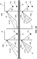
- FIG 8 Another further -third- position of the driver's eyes is added in Figure 8 , so that the variation of the optical lines as the driver moves his/her head can be shown.
- the depicted square (1001) in the mirror (1000) represents the lens of the camera of the CMS
- the depicted triangle (1002) represents the FOV of said CMS camera associated with the rear-view mirror (1000), i.e., equivalent to the captured image.
- Figure 8 shows the comparison between the image of captured by the exterior side camera, associated with the rear-view mirror (1000), and the optical lines of a conventional reflective rearview mirror.
- first position (E61), second position (E62) and third position (E63) become gradually more inclined, so when the driver's eye moves closer to the mirror (1000), the relative angle makes the images observed by the reflective mirror(1000) be not consistent with the true magnitude (and therefore the difference between the CMS image -merely a symmetry- and the reflected image becomes increasingly more accentuated). It is very important to note that both images (the reflective image and the displayed image) are not the same, and the difference is accentuated more as the driver's head position goes more forward (i.e., as the relative angle between camera / mirror and the driver's head varies).
- Figure 9 shows a triangle (1003) which represents the crop within the captured image, the captured image represented by the other triangle being either the raw image or its symmetrical image.
- Figure 9 shows the difference between the image perceived by the driver using the reflective image of the conventional mirror and the image displayed by the driver's display device.
- the aperture angle ( ⁇ ) of the displayed FOV does not change when the position of the driver's head change. More particularly, the value of aperture angle ( ⁇ ) remains fixed when the relative angle between CMS and driver's head changes.
- the displayed FOV or crop i.e., the image region (210)
- the displayed FOV or crop does change when the position of the driver's head changes (its relative angle alpha changes), as the image region (210) is moved within the captured image.
- the aperture angle ( ⁇ ) of the image region (210) keeps fixed because said angle ( ⁇ ) is independent of the detected head/body position, but the image region (210) represented in Figure 9 by the triangle (1003), is moved at least horizontally within the captured image.
- the captured image is a mere symmetry of the raw image captured by the image capturing means of the CMS. If there were a wall behind the vehicle (10), the camera could not capture any image behind the wall and so the triangle (1003) would get truncated.
- The, aperture, angle ( ⁇ ) of the triangle (1003) is the same for the first position (E61) as for the second position (E62) and the third position (E63).
- the image region (210) to be displayed comprises a fixed aperture angle ( ⁇ ) of FOV.
- Figure 10 shows a comparison between the aperture angle (a1', a2') of the conventional reflective rear-view mirror (1000) -upper quadrants A of Figure 10 - and the aperture angle (C1, C2) of a preferred embodiment of the invention -bottom quadrants B of Figure 10 . Also, Figure 10 illustrates the relative angle (X1, X2) between the obtained position of the part of the driver's body (e.g., the driver's head) and:
- the angle of the driver's view (a1') with respect to the reflective rear-view mirror (1000) corresponding to this first position (E11), represented at the left side of Figure 10 is greater than the angle of the driver's view (a2') corresponding to the second position (E12), represented at the left side of Figure 10 ; i.e., a1' > a2', as explained before in Figure 7 .
- Figure 10 also shows the optical axis (E1, E2) as the bisector of the triangle that represents the FOV for the first position (E11) and the second position (E12) respectively; the FOV being directly shown to the driver in the reflective rear-view mirror (1000) in the case of a conventional system represented in the upper part (A) of Figure 10 , the FOV being displayed, as a crop, according to a preferred embodiment of the invention represented in the lower part (B) of Figure 10 .
- the driver's eyes go to the first position (E11) to the second position (E12), in the example of Figure 10 :
- the relative angle between the driver's eyes and the conventional side exterior rear-view mirror (1000) is not the relative angle between the driver's eyes and the camera located on the exterior side and associated with the exterior rear-view mirror.
- the reflective mirror is replaced by an exterior camera which does not have to be located exactly where it is in the mirror (for example, it could be a little lower and not visible to the driver).
- trucks it is very likely that the rearview mirror is not replaced by an exterior camera, both the mirror and the camera co-exist and work in complementary way.
- the distance between the driver's eyes and the rear-view mirror In the second position (E12), the driver's head is closer to the rear-view mirror, so there is a "zoom in", the "zoom in” reducing the aperture angle (C1, C2) of the single crop. Therefore, the angle (C1, C2) of the displayed FOV is constant for the variation of the angle X1, X2, but changes when "zooming in/out".
- an interior camera of the vehicle capturing images of the driver and functioning as a gesture detector can sense, not only the position/movement of his/her head but also detect the eyes. Then, the ECU can optionally establish a midpoint between the two eyes from the images provided by said interior camera (the gesture detector): the detection of the head can be established as the midpoint between the eyes. Another option is to calculate the outline of the head.
- the camera can capture different parts of the face (ears, mouth / lips, nose, etc.).
- Figure 11 shows another, second, embodiment where the displayed image region (210) comprises two image regions or crops selected by the ECU: a first crop (210') and a second crop which corresponds to an additional extended view (220).
- the first crop (210') is selected by the electronic control unit, ECU, from the captured image (200) and encompasses a portion of the exterior part of the vehicle (10).
- the additional extended view (220) is a second crop selected by the ECU from the captured image (200), where said additional extended view (220) is located near the first crop (210'). As shown in figure 11 , it may be particularly located next to the first crop (210'), i.e., adjacent to the first crop (210'), and may preferably have the same height as the first crop (210').
- the gesture detector is configured to obtain at least one position of at least one part of the driver's body (e.g., the driver's head), and the ECU is configured to adjust the displayed image region (210) of the exterior FOV based on the at least one obtained position, by expanding in length the additional extended view (220) when the detected relative angle (X1, X2) between the driver's head and the camera monitoring system - i) camera for ERMS or ii) display for IRMS- is increased.
- the gesture detecture detects that the relative angle (X1, X2) increases (i.e., when the driver moves his/her head forward before overtaking)
- the ECU is configured to lengthen (i.e., to expand) horizontally outwardly the additional extended view (220).
- the ECU when the gesture detecture detects that the relative angle (X1, X2) decreases, then the ECU is configured to shorten (i.e., contract) horizontally inwardly the additional extended view (220) back to the original situation. It is preferred that the ECU is configured to expand or retract progressively as the relative angle (X1, X2) increases or decreases respectively. It is important to note that the shown example increases the aperture angle ( ⁇ ) of the image region (210) as increases the relative angle of the driver's head with respect to the CMS. Therefore, the additional extended view (220) causes an improved field of view of the exterior lateral adjacent area of the driver's vehicle because it reduces the blind spot zone when overtaking.
- the driver will always see at least a portion of the exterior side of the vehicle at all times even when the head moves forward. This is, the first crop (210') remains fixed (i.e., unchanged) regardless of the driver's head movement.
- the length of the additional extended view (220) is increased, at least, when the driver moves his/her head forward.
- the additional extended view (220) progressively increases / decreases its horizontal length as a result of an increase / decrease of the relative angle between the driver's head and the display device; while the first crop (210') remains unchanged regadless of the driver's head movement to ensure an exterior lateral portion of the vehicle is permanently displayed.
- the first crop (210') once displayed is smaller than the display device.
- the display device is large enough to display both crops: (210') and the additional extended view (220).
- said additional extended view (220) may be switched off if head movements are not detected (i.e., during the normal driving condition, the driver is not overtaking).
- the relative angle between the driver's head and the display device is increased, so when the ECU detects that it passes a threshold, the ECU is configured to generate the extended view (220) without modifying the first crop (210').
- the first crop (210') is not displayed on the entire screen size. Due to the fact that the first crop (210') is smaller than the actual size of the display device, there is space available to show, as depicted in Figure 11 , and subsequently to expand the additional extended view (220).
- the first crop (210') is always displayed while driving, and is fixed (i.e., constant over time) both in location within the capture image (200) and in size and shape.
- the additional extended view (220) may not be fixed since it may increase its length. This is, the aperture angle ( ⁇ ) of the whole, displayed, image region (210) is increased based on the detected increase in the relative angle (X1, X2).
- Figure 11 also shows the relationship between the movement of the driver's head detected by a sensor (gesture detector) and the expansion of the displayed additional extended view (220) within the captured image 200, according to a possible example.
- the movement of the driver's head along the driving direction is translated into a growth of the displayed additional extended view (220) processed (by the ECU) in the horizontal direction. Therefore, the change (i.e., adjustment) in the Field of View, FOV, seen by the driver is performed indirectly, by lengthening of the second crop (220), which results in a new FOV seen by the driver.
- FOV Field of View
- the ECU performs image processing to:
- the digital expansion of the displayed additional extended view 220 may be according to a pre-established relationship.
- the pre-established relationship may be linear or non-linear (see Figure 3 ).
- the first crop (210') is displayed permanently while the vehicle is running.
- the ECU is configured to generate the instruction to at least horizontally enlarged the additional extended view (220) by 40% of the total length of the first crop (210'). This corresponds to the case when the driver has moved his/her head 200 millimetres forward, i.e. in the driving direction of the vehicle (10).
- the ECU is configured to horizontally expand the additional extended view (220) displayed to reach the limit of the captured image (200).
- the first crop (210') is at the right side of the captured image when the driver's head is in the usual driving position, while the additional extended view (220) expands to the left, as shown in Figure 11 , when the head moves forward. That is, the first crop (210') is initially not centered on the captured image but is usually located at the right side. Therefore, the driver is provided with a path on the display to increase the length of the additional extended view (220) along the horizontal axis of the captured image which is much longer.
- the first crop (210') is not centered so as to leave an available space on its left within the captured image (200) that is not displayed.
- the length (L2) of said space is at least 20% of the length (L1) of the first crop 210'.
- the length (L2) is at least twice as long as the smallest length (L3) left from the right border of the captured image (200).
- the linear movement of the additional extended view may be vertical, horizontal, and ultimately said second crop may be moved diagonally (not shown).
- the sensor may be configured to detect the, at least one part, of the driver's body in the three-dimensional space, and wherein the ECU may configured to select an additional extended view (220) located up to the first image region (210'), wherein the additional extended view (220) progressively extends its heigh vertically downwards within the captured image (200) according to the determined body movement in a vertical direction, and wherein the first image region (210') remains fixed (i.e., unchanged) (not shown).
- the first and the second crops (210', 220) forming the displayed image region (210) may optionally be zoom in / out. Zoom out is increasing the size of any of the two crops (210' 220), whereas zoom in is decreasing the size of any of said crops (210', 220).
- the gesture detector is a camera, it is possible to detect the driver's gaze, i.e. at which point the driver is looking. Therefore, according to a further possible example, the ECU can carry out the digital expansion of the additional extended view (220) when a head movement is detected and also if the driver is looking at the display device.
- the additional extended view (220) is not displayed. So, the additional extended view (220) is not always displayed each time the driver moves his/her head, only when the detected gesture complies with a threshold or certain criteria.
- the driver's head could be detected on three axes, x, y and z, with the driving axis, denoted as x, being essential and the other two axes being optional / additional.
- the ECU can work both with the locations of the head and with a relative angle of the head with respect to the driver's display. If the driver moves his/her head forward, he/she is increasing the alpha angle and is expanding the additional extended view (220) to the left in the display, at least in a straight direction according to the horizontal axis, x.
- Figure 12 shows from a top view the increase of the aperture angle ( ⁇ 1, ⁇ 2) as the driver's head moves forward for overtaking another vehicle (10').
- the aperture angle has an initial value ( ⁇ 1).
- the driver of the vehicle (10) starts to overtake the other vehicle (10').
- the driver's head goes to a second position (E52) and the aperture angle takes another value (a2), being ⁇ 2> ⁇ 1.
- This increase of the aperture angle is translated into an increase in the horizontal length of the displayed image region (210), as shown in Figure 11 , because the extendable second crop (220) is added to the first crop (210') and expanded outward horizontally.
- Figure 13 shows another option for the extendable second crop (220) added to the first crop (210') to form the displayed image region (210), which can be vertically expanded downwardly when the driver's head moves a few millimetres upward, e.g., for parking to see the ground and check any curb or another obstacle.
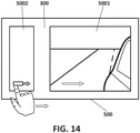
- Figure 14 shows the CMS is provided with an electronic display device (500) having two different portions: a first portion (5001) in which the the first crop 210' is displayed, and a second portion (5002) in which the additional extended view (220) is displayed.
- the display device (500) is one single screen, prefereably a touch screen.
- the display device (500) comprises two different screens. Having two screens, the first portion (5001) distinguised by the ECU may be implemented in the first screen, which can be touchless and then cheaper, and the second portion (5002) may be implemented in the second screen, which can be touch-sensitive.
- the second portion (5002) is preferably smaller than the first portion (5001).
- One technical advantage is the cost of non-touch-sensitive screens.
- the driver may perform a "touch & drag" operation in the second portion (5002) so as to move the display image region (210). It may be advantageous for the initial calibration of the camera monitoring system, CMS, when the driver is about to start driving. The technical advantage of doing so is that the first portion (5001) does not get dirty. Further, the second portion (5002) may display the parameters related to brightness and/or contrast and/or color of the first portion (5001). As explained, the second screen only displays the additional extended view (220) when the ECU determines the additional extended view (220) has to be displayed, whereas the first screen shows permanently the first crop (210') while the engine of the vehicle (10) is on.
- the driver can calibrate the CMS so that a movement of the driver's thumb indicating the OK symbol can switch on the additional extended view (220).
- the first crop (210') displayed on the first screen is fixed (i.e., does not vary by changing the location of the driver's head), so it is ensured to display at least a portion of the exterior side of the vehicle (10) at all times when the engine is running even when the driver's head is moved forward.
- the CMS further comprises a frame (300) covering at least partially the display device (500).
- This frame (300) has the same dimensions as the display device (500) or significantly larger to cover at least the entire display device (500).
- the frame (300) is a cover, preferably made of plastic or glass, which also protects the display device (500) from impacts and damages, since the touch screen may be relatively fragile.
- the frame (300) may be partially tinted. Preferably, the tinting is black. Said frame (300) does not allow all the light emitted by the display device (500) can pass through.
- the frame (300) is placed, for example, on top of the touch screen, and so what the user sees is the "frame", since it is placed between the screen and the user.
- a third embodiment of the present invention comprises two states of operation for the display device (500): a first state corresponds when the gesture detector detects that the detected driver's head passes a threshold, e.g., when overtaking, then the second image region as an additional extended view (220) is displayed (i.e. switched on), as shown in the right picture of Figure 15 , in full on the second portion (5002).
- a second state corresponds when the second image region (220) is not displayed at all when the driver's head is detected to be back to the original position (i.e. normal driving), i.e. the second portion (5002) is switched off, as shown in the left picture of Figure 15 .
- a difference between the second embodiment and the third embodiment is that the extended view of the second embodiment is continuously extended or retracted, whereas the third embodiment is entirely displayed (i.e., first state) or not displayed (i.e., second state).
- the ECU may generate a black image for the second state.
- dark colours such as black have low power consumption if displayed in LED screens such as an OLED display device.
- another further -fourth- embodiment is related to sensitivity, i.e., the speed of changing the FOV (the speed of moving the crop or increasing the size of the additional extended view).
- the proposed CMS allows the user to calibrate said sensitivity; for example, if the driver moves his/her head 10 centimetres, the crop is moved 10 millimetres; but if the driver moves his/her head 20 centimetres, the crop is only moved 10 millimetres.
- a first driver wants the displayed image to be moved only 1 centimetre horizontally within the captured image
- a second driver may want the displayed image to be moved 2 centimetres horizontally within the captured image. That is, not all the head movements produce the same displacement of the crop and the system can be customized according to the driver's preferences for controlling the speed of said displacement/movement (panning).
- This sensitivity calibration also applies to the second embodiment, in which the aperture ( ⁇ ) of the image region (210) increases by expanding (extending / lengthen) the additional extended view as the detected relative angle increases.
- the movement of the driver's part of the body detected by the sensor is at least in the driving direction of the vehicle, and the panning is at least linear and horizontal accordingly.
- it can also be in the vertical plane (perpendicular to the ground plane), and the panning movement is linear and vertical, or a combination of horizontal and vertical, i.e. diagonal, accordingly.
- the movement of the crop is performed by comparing a reference position of the driver's head with its current position. Both positions can be calculated for the driver's head or any other part of the driver's body or head, preferably the face. Therefore, the reference position is not calculated with respect to a fixed element (of the car), but with respect to a part of the driver's upper body.
- the system is calibrated before the driver starts driving. The system is configured to save the driver's personal settings in order to detect each user and load his/her stored profile. Therefore, while driving, the movement of the displayed image change according to said sensitivity customisation (calibration).
- the FOV will change a few little, whereas other drivers will desire greater sensitivity, in which the FOV can change significantly by moving their head just a little.
- the user can calibrate (customise the sensitivity of) the camera monitoring or vision system (CMS) of any of the electronic rear-view mirrors (interior and/or any of the side mirrors).
- CMS camera monitoring or vision system
- Customisation of the sensitivity of the proposed system comprises, according to a possible example, the following steps:
- the gesture detector is configured to perform the "calibration", wherein, for initial "calibration", the user/driver customises the desired sensitivity.
- the gesture detecting sensor detects a first position (e.g., of the head) and a second position (of the head).
- the driver selects / determines the FOV associated with the first position (determines the position of the crop) and a second FOV of the second position (determines the adjusted position of the crop).
- the ECU determines the displacement of the displayed image/crop.
- the sensor detects the position of the driver's head with respect to the initial reference position. Based on the comparison of the reference position (first position) with the second position, the displayed image is shifted (moved). Both positions are dynamic, they have not fixed values because the driver can change the initial reference position of his/her head.
- the driver associates the first position with a given FOV and the second position with another FOV.
- the calibration is optional and carried out before driving: the user sits in the driver's seat and in a first position, for example, in his/her usual driving position, selects a first FOV (location of the crop) to be seen on the display. Then a relationship is established between the first position and the associated first FOV (location of the crop) which the driver wants to see when he/she is in said position. Then, the driver changes the position of the body/head, for example, he/she moves his/her head forward, in a second position corresponding to the position that the driver would occupy if he/she were about to change lane to pass (i.e., overtake) the car in front of him/her.
- a first position for example, in his/her usual driving position
- the driver selects the second FOV that he/she wants to see on the display when he/she is in said second position. Therefore, the ECU has at least two positions of the driver's body/head, with their respective first and second FOVs. At this point, the ECU establishes a (linear or non-linear) relationship based on these positions input by the driver, i.e., if the driver is in an intermediate position while driving, the crop (displayed image) moves in an intermediate position between the positions corresponding to the first FOV and the second FOV. If this relationship is linear, this means that the variation between the first position and the second position is proportional, but it may also not be proportional.
- the reference position (first position) can be calculated as follows:
- the ECU has several ways to determine the movement of the crop (digital panning):
- the sensor or gesture detector is, for example, a camera (although it could be radar or another technology).
- the ideal situation is for it to always find a representative point of the face / body. If it is a camera, it can detect any facial expression, especially the eyes, so it would find the midpoint between the two eyes. If it is radar, detection could be done by finding the outline of the face, and then finding the midpoint (height of the head divided by two, and width of the head divided by two).
- the movement of the crop, the speed of this movement (sensitivity, as explained before) and/or the size of the crop can be changed depending on the yaw angle, pitch angle or roll angle, the turn signal, or a movement of the steering wheel.
- a last example of the proposed camera monitoring system, CMS comprises:
- the adjusted image region (210) is smaller than the captured image (200) and, optionally, is not centered on the captured image; instead, the image region (210), which is displayed by the electronic display device, is located at an inner, right or left, side of the captured image, so as the driver is provided with a path on the display to:
Priority Applications (4)
| Application Number | Priority Date | Filing Date | Title |
|---|---|---|---|
| EP20382801.7A EP3967552A1 (fr) | 2020-09-11 | 2020-09-11 | Système de surveillance de caméra pour véhicules à moteur |
| CN202111064047.0A CN114248689B (zh) | 2020-09-11 | 2021-09-10 | 用于机动车的摄像头监测系统及其图像显示方法 |
| JP2021147247A JP2022047522A (ja) | 2020-09-11 | 2021-09-10 | 自動車用カメラ監視システム |
| US17/473,194 US11694448B2 (en) | 2020-09-11 | 2021-09-13 | Camera monitoring system for motor vehicles |
Applications Claiming Priority (1)
| Application Number | Priority Date | Filing Date | Title |
|---|---|---|---|
| EP20382801.7A EP3967552A1 (fr) | 2020-09-11 | 2020-09-11 | Système de surveillance de caméra pour véhicules à moteur |
Publications (1)
| Publication Number | Publication Date |
|---|---|
| EP3967552A1 true EP3967552A1 (fr) | 2022-03-16 |
Family
ID=72709277
Family Applications (1)
| Application Number | Title | Priority Date | Filing Date |
|---|---|---|---|
| EP20382801.7A Pending EP3967552A1 (fr) | 2020-09-11 | 2020-09-11 | Système de surveillance de caméra pour véhicules à moteur |
Country Status (4)
| Country | Link |
|---|---|
| US (1) | US11694448B2 (fr) |
| EP (1) | EP3967552A1 (fr) |
| JP (1) | JP2022047522A (fr) |
| CN (1) | CN114248689B (fr) |
Cited By (1)
| Publication number | Priority date | Publication date | Assignee | Title |
|---|---|---|---|---|
| US20210370773A1 (en) * | 2018-05-08 | 2021-12-02 | Sony Semiconductor Solutions Corporation | Image processing apparatus, moving apparatus, method, and program |
Families Citing this family (1)
| Publication number | Priority date | Publication date | Assignee | Title |
|---|---|---|---|---|
| WO2022192663A1 (fr) * | 2021-03-12 | 2022-09-15 | Stoneridge, Inc. | Système de miroir de caméra de véhicule à flux vidéo réglable |
Citations (7)
| Publication number | Priority date | Publication date | Assignee | Title |
|---|---|---|---|---|
| DE102007044536A1 (de) * | 2007-09-18 | 2009-03-19 | Bayerische Motoren Werke Aktiengesellschaft | Vorrichtung zum Überwachen der Umgebung eines Kraftfahrzeugs |
| US9073493B1 (en) | 2014-04-10 | 2015-07-07 | Qualcomm Incorporated | Method and apparatus for adjusting view mirror in vehicle |
| WO2016178190A1 (fr) * | 2015-05-06 | 2016-11-10 | Magna Mirrors Of America, Inc. | Système de vision pour véhicule ayant un système d'alerte et d'affichage de zone aveugle |
| US20180050639A1 (en) * | 2016-08-19 | 2018-02-22 | Panasonic Automotive Systems Company Of America, Division Of Panasonic Corporation Of North America | Reactive smart rear view display mirror |
| US20180304814A1 (en) * | 2017-04-24 | 2018-10-25 | Panasonic Automotive Systems Company Of America, Division Of Panasonic Corporation Of North America | Rear view mirror-like perspective change system and method |
| US20190197327A1 (en) * | 2017-12-22 | 2019-06-27 | Texas Instruments Incorporated | Digital mirror systems for vehicles and methods of operating the same |
| US20200231091A1 (en) * | 2019-01-23 | 2020-07-23 | Honda Motor Co., Ltd. | Display system, vehicle control apparatus, display control method, and storage medium for storing program |
Family Cites Families (12)
| Publication number | Priority date | Publication date | Assignee | Title |
|---|---|---|---|---|
| WO2006043721A1 (fr) * | 2004-10-20 | 2006-04-27 | Fujitsu Ten Limited | Dispositif d’affichage |
| EP1990674A1 (fr) * | 2007-05-09 | 2008-11-12 | Harman Becker Automotive Systems GmbH | Système d'affichage monté sur tête |
| US9102269B2 (en) * | 2011-08-09 | 2015-08-11 | Continental Automotive Systems, Inc. | Field of view matching video display system |
| JP6011104B2 (ja) * | 2012-07-24 | 2016-10-19 | 株式会社デンソー | 車両用視界支援装置 |
| GB2508860A (en) * | 2012-12-13 | 2014-06-18 | Nissan Motor Mfg Uk Ltd | Vehicle Rear-View Camera System |
| CN105075247B (zh) * | 2013-02-28 | 2018-08-14 | 爱信精机株式会社 | 车辆的控制装置及存储介质 |
| US10946798B2 (en) * | 2013-06-21 | 2021-03-16 | Magna Electronics Inc. | Vehicle vision system |
| CN106660485B (zh) * | 2014-06-19 | 2020-04-21 | 依维柯股份公司 | 用于辅助车辆驾驶的后视系统 |
| JP6582644B2 (ja) * | 2014-08-11 | 2019-10-02 | セイコーエプソン株式会社 | 撮像装置、撮像表示装置、及び、車両 |
| JP6686886B2 (ja) * | 2014-08-12 | 2020-04-22 | ソニー株式会社 | 信号処理装置と信号処理方法およびモニタリングシステム |
| JP6669019B2 (ja) * | 2016-09-08 | 2020-03-18 | 株式会社Jvcケンウッド | 車両用表示制御装置、車両用表示システム、車両用表示制御方法およびプログラム |
| JP6744236B2 (ja) * | 2017-02-08 | 2020-08-19 | トヨタ自動車株式会社 | 画像表示装置 |
-
2020
- 2020-09-11 EP EP20382801.7A patent/EP3967552A1/fr active Pending
-
2021
- 2021-09-10 CN CN202111064047.0A patent/CN114248689B/zh active Active
- 2021-09-10 JP JP2021147247A patent/JP2022047522A/ja active Pending
- 2021-09-13 US US17/473,194 patent/US11694448B2/en active Active
Patent Citations (7)
| Publication number | Priority date | Publication date | Assignee | Title |
|---|---|---|---|---|
| DE102007044536A1 (de) * | 2007-09-18 | 2009-03-19 | Bayerische Motoren Werke Aktiengesellschaft | Vorrichtung zum Überwachen der Umgebung eines Kraftfahrzeugs |
| US9073493B1 (en) | 2014-04-10 | 2015-07-07 | Qualcomm Incorporated | Method and apparatus for adjusting view mirror in vehicle |
| WO2016178190A1 (fr) * | 2015-05-06 | 2016-11-10 | Magna Mirrors Of America, Inc. | Système de vision pour véhicule ayant un système d'alerte et d'affichage de zone aveugle |
| US20180050639A1 (en) * | 2016-08-19 | 2018-02-22 | Panasonic Automotive Systems Company Of America, Division Of Panasonic Corporation Of North America | Reactive smart rear view display mirror |
| US20180304814A1 (en) * | 2017-04-24 | 2018-10-25 | Panasonic Automotive Systems Company Of America, Division Of Panasonic Corporation Of North America | Rear view mirror-like perspective change system and method |
| US20190197327A1 (en) * | 2017-12-22 | 2019-06-27 | Texas Instruments Incorporated | Digital mirror systems for vehicles and methods of operating the same |
| US20200231091A1 (en) * | 2019-01-23 | 2020-07-23 | Honda Motor Co., Ltd. | Display system, vehicle control apparatus, display control method, and storage medium for storing program |
Cited By (2)
| Publication number | Priority date | Publication date | Assignee | Title |
|---|---|---|---|---|
| US20210370773A1 (en) * | 2018-05-08 | 2021-12-02 | Sony Semiconductor Solutions Corporation | Image processing apparatus, moving apparatus, method, and program |
| US11958358B2 (en) * | 2018-05-08 | 2024-04-16 | Sony Semiconductor Solutions Corporation | Image processing apparatus, moving apparatus, method, and program |
Also Published As
| Publication number | Publication date |
|---|---|
| US20220083794A1 (en) | 2022-03-17 |
| CN114248689B (zh) | 2024-04-02 |
| JP2022047522A (ja) | 2022-03-24 |
| CN114248689A (zh) | 2022-03-29 |
| US11694448B2 (en) | 2023-07-04 |
Similar Documents
| Publication | Publication Date | Title |
|---|---|---|
| CN107444263B (zh) | 车辆用显示装置 | |
| US11034299B2 (en) | Vehicular vision system with episodic display of video images showing approaching other vehicle | |
| US10029621B2 (en) | Rear view camera system using rear view mirror location | |
| US11694448B2 (en) | Camera monitoring system for motor vehicles | |
| US10363876B2 (en) | Image display device | |
| JP6361988B2 (ja) | 車両用表示装置 | |
| US20210392297A1 (en) | Driver monitoring system using camera with adjustable mirror | |
| WO2014130049A1 (fr) | Systèmes et procédés d'affichage augmenté pour rétroviseurs | |
| JP6360850B2 (ja) | 画像表示装置 | |
| JP6770330B2 (ja) | 画像表示装置 | |
| US10390001B2 (en) | Rear view vision system for a vehicle | |
| WO2019034916A1 (fr) | Système et procédé de présentation et de commande d'image de caméra virtuelle pour un véhicule | |
| JP2017056909A (ja) | 車両用画像表示装置 | |
| JP2007230491A (ja) | 視覚情報呈示装置及び視覚情報呈示方法 | |
| KR102347876B1 (ko) | 증강현실 헤드업 디스플레이의 표시 위치 제어 장치 | |
| JP7398637B2 (ja) | 表示制御装置、車両及び表示制御方法 | |
| JP6459071B2 (ja) | 車両用表示装置 | |
| JP2006137209A (ja) | 車両用防眩装置 | |
| JP2017213935A (ja) | 車両用表示装置 | |
| JP7429865B2 (ja) | 表示制御装置、車両及び表示制御方法 | |
| US20220292841A1 (en) | Vehicle camera mirror system with adjustable video feed | |
| EP4306363A1 (fr) | Système et procédé pour fournir une image composite d'un véhicule et de son environnement | |
| CN117261768A (zh) | 一种自动调节视野的电子后视镜控制方法及其系统 | |
| CN111201159B (zh) | 用于机动车辆的改进的视频后视系统 | |
| KR20230000482A (ko) | 디지털 사이드 미러 제어 시스템 및 방법 |
Legal Events
| Date | Code | Title | Description |
|---|---|---|---|
| PUAI | Public reference made under article 153(3) epc to a published international application that has entered the european phase |
Free format text: ORIGINAL CODE: 0009012 |
|
| STAA | Information on the status of an ep patent application or granted ep patent |
Free format text: STATUS: THE APPLICATION HAS BEEN PUBLISHED |
|
| AK | Designated contracting states |
Kind code of ref document: A1 Designated state(s): AL AT BE BG CH CY CZ DE DK EE ES FI FR GB GR HR HU IE IS IT LI LT LU LV MC MK MT NL NO PL PT RO RS SE SI SK SM TR |
|
| STAA | Information on the status of an ep patent application or granted ep patent |
Free format text: STATUS: REQUEST FOR EXAMINATION WAS MADE |
|
| 17P | Request for examination filed |
Effective date: 20220909 |
|
| RBV | Designated contracting states (corrected) |
Designated state(s): AL AT BE BG CH CY CZ DE DK EE ES FI FR GB GR HR HU IE IS IT LI LT LU LV MC MK MT NL NO PL PT RO RS SE SI SK SM TR |
|
| STAA | Information on the status of an ep patent application or granted ep patent |
Free format text: STATUS: EXAMINATION IS IN PROGRESS |
|
| 17Q | First examination report despatched |
Effective date: 20240214 |