EP3967549B1 - Lagervorrichtung für eine kopfstütze - Google Patents
Lagervorrichtung für eine kopfstütze Download PDFInfo
- Publication number
- EP3967549B1 EP3967549B1 EP21191877.6A EP21191877A EP3967549B1 EP 3967549 B1 EP3967549 B1 EP 3967549B1 EP 21191877 A EP21191877 A EP 21191877A EP 3967549 B1 EP3967549 B1 EP 3967549B1
- Authority
- EP
- European Patent Office
- Prior art keywords
- bearing device
- bolt
- band
- latch
- guide part
- Prior art date
- Legal status (The legal status is an assumption and is not a legal conclusion. Google has not performed a legal analysis and makes no representation as to the accuracy of the status listed.)
- Active
Links
Images




Classifications
-
- B—PERFORMING OPERATIONS; TRANSPORTING
- B60—VEHICLES IN GENERAL
- B60N—SEATS SPECIALLY ADAPTED FOR VEHICLES; VEHICLE PASSENGER ACCOMMODATION NOT OTHERWISE PROVIDED FOR
- B60N2/00—Seats specially adapted for vehicles; Arrangement or mounting of seats in vehicles
- B60N2/80—Head-rests
- B60N2/806—Head-rests movable or adjustable
- B60N2/809—Head-rests movable or adjustable vertically slidable
- B60N2/812—Head-rests movable or adjustable vertically slidable characterised by their locking devices
- B60N2/815—Release mechanisms, e.g. buttons
-
- B—PERFORMING OPERATIONS; TRANSPORTING
- B60—VEHICLES IN GENERAL
- B60N—SEATS SPECIALLY ADAPTED FOR VEHICLES; VEHICLE PASSENGER ACCOMMODATION NOT OTHERWISE PROVIDED FOR
- B60N2/00—Seats specially adapted for vehicles; Arrangement or mounting of seats in vehicles
- B60N2/80—Head-rests
- B60N2/806—Head-rests movable or adjustable
- B60N2/809—Head-rests movable or adjustable vertically slidable
- B60N2/812—Head-rests movable or adjustable vertically slidable characterised by their locking devices
- B60N2/818—Head-rests movable or adjustable vertically slidable characterised by their locking devices with stepwise positioning
Definitions
- the invention relates to a bearing device for a support rod of a headrest.
- the bearing device comprises a locking device with which the support rod can be releasably locked in at least one position.
- Such a bearing is known from prior public use.
- the bearing comprises a guide sleeve that can be attached to the backrest of a vehicle seat.
- a slide is movably guided on the guide sleeve.
- a latch is held on the slide, which interacts with at least one recess in the support rod.
- the latch is loaded by a spring into engagement with the recess. By operating the slide, the latch can be moved from the locking position to a release position in which the support rod can be moved freely in the directions z1 and z2 relative to the guide sleeve.
- the WO 2011/088167 A1 describes a seat device with a backrest comprising side parts and a cross member, which has a first and a second opening each for receiving support rods of a headrest.
- the cross member also has means for locking and unlocking the support rod.
- the bearing device is intended for supporting a headrest with at least one support rod.
- the support rod is part of the bearing device.
- the support rod can be, for example, a single rod or a free end of a support rod bracket.
- the bearing device also comprises a guide part with which the support rod of the headrest can be supported on a vehicle seat.
- the guide part is attached to the vehicle seat, in particular to a backrest of the vehicle seat.
- the guide part comprises bearing surfaces which guide and hold the support rod in a locking position during assembly in the guide part and during disassembly.
- the bearing device comprises a locking device by means of which the support rod can be releasably secured in a locking position relative to the guide part.
- the locking device comprises a latch that can be moved between a locking position and a release position, which is associated with the guide part, and at least one recess that is associated with the support rod. In the locking position, the latch is in engagement with the recess. The holding rod is then held immovably in the locking position. In the release position, the latch and recess are disengaged, so that the holding rod can be moved out of the locking position.
- the locking device can be adjusted between the locking position and the release position using an actuating device.
- the actuation is carried out manually or by motor.
- the bolt is loaded into the locking position by a reset element.
- the reset takes place by releasing the force on the actuation.
- the actuating device comprises a force transmission connection in the form of a band, e.g. a band guided like a pulley.
- the latch can be adjusted to the release position by a resulting actuating force.
- a second force component moves the ejector from a first position to a second position, e.g. via the connection, whereby the ejector moves the holding rod from the locking position to a removal position.
- the second force component supports the movement to the removal position.
- the bearing device comprises, for example, an ejector, which is intended to move the holding rod from the locking position to a removal position.
- a further resulting actuating force acts, for example, on the ejector and loads it from a first position to a second position.
- the ejector is connected to the holding rod in such a way that the holding rod is arranged in a locking position when the ejector is in the first position and is arranged in a removal position when the ejector is in the second position.
- the holding rod In the locking position, the holding rod is arranged in a seat of the guide part, for example. In the removal position, the holding rod is moved out of the seat, for example in the disassembly direction.
- the actuating device comprises a band which forms the connection.
- the band is made of textile, metal or plastic, for example, or a composite material.
- the band should be able to transmit tensile forces to a sufficient extent.
- the band comprises, for example, an actuating area which interacts with an abutment of the latch, such that when a tensile force is applied to the band, a force is exerted on the abutment which Latch is moved to the release position.
- the operating area is arranged between the end areas of the strap.
- the band is deflected at the abutment from a first direction of extension to a second direction of extension.
- a resulting force of the actuation force acts on the latch, causing the latch to move from the locking position to the release position.
- the band is loosely guided around the abutment of the latch and moves relative to the abutment.
- An end area of the band facing away from the actuation is, for example, firmly attached to the guide part or, alternatively, the force resulting at this end area is used to move another part, e.g. an ejector.
- the bolt is in contact with a first stop in the locking position and with a second stop on the guide part in the release position.
- the stops represent a movement limit for the bolt.
- a force can be transferred from the bolt or a bolt holder to the guide part using the stops.
- a force resulting from the actuating force can move the latch into the release position and a further resulting force can load the ejector. If a pulling force is applied to the band, the latch is then initially moved into the release position due to the resulting force, in which the latch or a latch holder is in contact with the second stop. After unlocking, a further resulting force can be absorbed by the guide part or this force can alternatively load the ejector in the direction of the second position and thus support the movement of the holding rod into the removal position.
- the actuating region is formed, for example, between a first end region and a second end region of the band.
- One end of the strap is designed for motor or manual operation. If operated manually, the strap can be provided with a loop for an advantageous grip.
- the latch is, for example, associated with a latch holder that is movably guided between the latch position and the release position.
- the latch holder can, for example, have a latch area or, alternatively, an additional latch element, such as a latch wire, is attached to the latch holder.
- the latch holder is associated with, for example, first guide means that interact with second guide means of the guide part in order to movably guide the latch holder in such a way that the latch can be moved between the latch position and the release position.
- the abutment for the band can, for example, be formed on the latch holder.
- the bolt holder is guided, for example, in a recess in the guide part.
- guide means e.g. in the form of sliding surfaces, are formed on the guide part, which interact with corresponding sliding surfaces of the bolt holder in order to movably guide the bolt holder with the bolt between the locking position and the release position.
- the latch is mounted so that it can move, for example, translationally or rotationally between the latch position and the release position.
- the latch is loaded into the latch position by a spring. In this way, when the actuating device is relieved of load, the latch is held in engagement with a recess. This ensures the safety of the bearing device.
- the ejector is mounted so that it can move in a translational or rotational manner, for example.
- the ejector can move parallel to the disassembly direction of the holding rod, for example.
- the rotational movement of an actuating surface of the holding rod is such that the holding rod can be moved by the ejector, at least over part of the movement, from the locking position to the removal position.
- the ejector for example, is additionally loaded by a spring in the ejection direction. After the holding rod is unlocked by moving the locking device from the locking position to the release position, the ejector is simultaneously loaded by the spring force and by the force exerted on the ejector via the connection in the disassembly direction. When the ejector moves from the first position to the second position, the spring relaxes, while the holding rod is moved in the disassembly direction to the removal position. If the holding rod is moved in the assembly direction to the locking position, the spring is tensioned.
- the support rod for example, has a conical shape at the end.
- this feature causes the latch to move out of the movement path of the support rod, so that the latch can automatically engage in the recess as soon as the support rod has reached the locking position.
- the conical shape of the support rod is assigned to a plastic part, for example, which is connected to the support rod.
- the support rod which is designed as a support rod tube, for example, can then be manufactured in the usual way, while the plastic part with the conical shape is produced by plastic injection molding.
- the bearing device as a whole is designated by the reference numeral 10 in the figures.
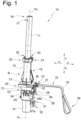
- the storage device 10 comprises according to Fig.1 a holding rod 11, a guide part 12, and a locking device 15 which can be actuated by means of an actuating device 16 for the locking device 15.
- the holding rod 11 is a single holding rod.
- a headrest part (not shown) is mounted, for example, on two bearing devices 10.
- the locking device 15 can be provided on just one of the bearing devices 10 or, alternatively, on both bearing devices 10.
- the support rod 11 is provided at an upper end region 18 with a fastening structure 17, with which the headrest part can be fastened to the support rod.
- the fastening structure 17 is designed as a recess, but other fastening structures can also be used.
- a lower end region 19 of the support rod 11 is accommodated in a guide recess 20 of the guide part 12.
- the guide part 12 is designed in two parts and has an upper guide part 13 and a lower guide part 14. The two-part design facilitates the assembly of the guide part 12.
- the upper guide part 13 has an annular thickening 22 which serves to accommodate a sliding bearing.
- first guide means 24 are formed, which interact with second guide means 25 of the lower guide part 14 in order to move the upper guide part 13 into a locking seat of the lower guide part and to connect these parts to one another in this way.
- the first guide means 24 are formed in the embodiment of webs 26a and 26b, wherein the web 26a engages in grooves 27a and the web 26b in grooves 27b.
- a hook structure 28 of the lower guide part 14 engages with a recess 29 of the upper guide part 13. In the locked state the upper guide part 13 and the lower guide part 14 cannot move relative to each other.
- a bearing structure 30 is formed on the guide upper part 13, which serves to guide a latch holder 31.
- the bearing structure 30 comprises a recess 32, on the inner surfaces of which the latch holder 31 is guided in such a way that it only has degrees of freedom in the directions y1 and y2.
- the latch holder can be moved in the directions y1 and y2 between a latch position and a release position, which is explained in more detail below.
- the movement of the latch holder 31 runs approximately at right angles to a longitudinal center axis m1 of the guide recess 20.
- a longitudinal center axis m2 of the holding rod 11 runs approximately parallel to the longitudinal center axis m1 when the holding rod is in the latch position or the removal position.
- the locking device 15 comprises the actuating device 16 with which the locking device 15 can be adjusted between the locking position and the release position.
- the locking device 15 is actuated manually using an actuation 63.
- a motor actuation could also be provided.
- the actuating device 16 comprises a band 33, wherein the band 33 is manually actuated at an end region 34.
- a loop is formed at the end region 34, to which a tensile force F1 can be applied to the band 33.
- another actuation 63 could also be provided, such as a handle or, alternatively or additionally, a connection to a motor drive.
- An end portion 35 of the band 33 is attached by means of a holder 37 to an ejector 36, which will be discussed further below.
- the band 33 runs from the holder 37 approximately parallel to the longitudinal center axis m1 approximately in the direction of the z-axis, being guided by a guide 38 of the guide part 12 on the outside of the guide part 12.
- the band 33 rests against an abutment surface 57 of an abutment of the latch holder 31, and is held against the abutment surface, which is in Fig.1 cannot be seen, is deflected approximately at a right angle in a direction parallel to the axis y.
- the abutment surface 57 forms a sliding bearing, over which the band 33 slides when it moves relative to the latch holder 31.
- a roller could also be provided over which the band 33 slides.
- the abutment surface 57 is formed by the reveal of a recess 39 of the latch holder 31.
- the abutment surface represents, for example, a pulley-like guide, so that a force F2 is absorbed at the abutment surface when a force F1 acts on the belt at the end region 34.
- the force F2 at the abutment surface 57 is, for example, twice as large as a force F1 that is applied to the holder 37 and also to the end region 34 of the belt.
- the belt can move relative to the abutment surface 57.
- Fig.2 is a side view of the device approximately according to arrow B in Fig.1 .
- the guide part 12 has sliding bearings 40 and 41, which are held at a distance from one another on the guide part and project radially into a guide space 42 of the guide part 12 in such a way that they can guide the holding rod 11 in the direction z1 during assembly and in the direction z2 during disassembly.
- a spring 44 is accommodated in a receiving space 43 of the guide part 12, which is supported with a spring end 45 on a base surface 46 of the guide part.
- a spring end 47 is in contact with a contact surface 48 of the ejector 36, such that the spring 44 can load the ejector 36 in the direction z1 when it is under tension.
- the ejector 36 is guided in the guide part 12 in such a way that it can only move in the directions z1 and z2. According to Fig.3 the spring 44 is tensioned.
- the ejector 44 has an actuating surface 49 which is in contact with a counter surface 50 of an attachment part 51 which is firmly connected to the lower end region 19 of the holding rod 11.
- the attachment part 51 comprises an inclined surface 59 which is designed in such a way that when the holding rod 11 is inserted in the direction z1 into the guide recess 20 of the guide part 12, a force can be exerted on the bolt located in the movement path in the direction y1, so that it moves out of the movement path in the direction y1.
- a conical, circumferential slope is formed on the attachment part 51.
- the attachment part 51 forms an extension of the support rod 11.
- the attachment part 51 is arranged in a seat 52 of the guide part 12.
- the seat 52 is formed by an inner surface 53 of the guide part 12, e.g. the guide lower part 14.
- a separate latch 54 is held on the latch holder 31.
- the latch 54 is formed, for example, by a wire which is attached to the latch 54, eg injected using a plastic injection molding process. Alternatively, the latch can also be formed by a surface of the latch holder 31, ie not be a separate part.
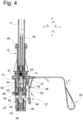
- the latch 54 is according to Fig.4 in engagement with a recess 55 of the support rod 11. The recess 55 is located on the outer surface 56 of the support rod 11.
- the latch 54 engages in the recess 55 approximately radially to the longitudinal center axis m1, such that it prevents movement of the holding rod 11 in the directions z1 and z2.
- the holding rod 11 cannot move in other spatial directions in the locking position either.
- the forces absorbed by the latch 54 are transferred to the latch holder 31 and from there to the guide part 12.
- a force F2 in the direction y1 acts on the band 33 when an actuating force F1 is applied to the abutment surface 57 of the latch holder 31.
- the force F2 causes the latch holder 31 to move in the direction y1, whereby the latch 54 moves out of engagement with the recess 55.
- the locking device has thus been moved from the latch position to the release position (see the Fig. 5 to 7 ).
- the surfaces 61 and 62 are spaced apart by a distance s1.
- the holding rod 11 Since the holding rod 11 is no longer locked in the locking position, it can be moved by the ejector 36 under the influence of the spring force and the force F1 into a removal position, which is in the Fig. 8 to 10
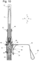
- the ejector 36 moves from a first position according to the Fig.3 and 4 in a second position according to Fig.10
- the surfaces 61 and 62 are spaced apart by the distance s2.
- the holding rod 11 In the removal position, the holding rod 11 cannot be relocked when the force on the band 33 decreases. Even if the latch holder 31 moves in the direction y2, the latch 54 strikes an outer surface 58 of the attachment part 51 of the holding rod 11, since the latch 54 and the recess 55 are in different positions with respect to the Z axis.
- the holding rod 11 can be removed from the guide space 42 by a movement in direction z1.
- the spring 60 (see Fig.10 ) in direction y2 is then moved in direction y2 until holding surfaces 61 of the latch holder 31 rest against a counter surface 62 of the guide part 12.
- the mounting of the holding rod 11 is carried out by moving the holding rod 11 in the mounting direction z2 into the guide space 42 until the inclined surface 59 of the attachment part 51 comes into contact with the latch 54 or the latch holder 31. With further movement in the direction z2, a force is exerted on the latch holder 31 in the direction y1, which moves the latch holder 31 in the direction y2 out of the path of movement of the holding rod 11.
- the holding rod 11 can therefore be moved further in the direction z2 until the attachment part 51 is arranged in the seat 52. The holding rod 11 is then back in the locking position.
- the latch 54 and the recess 55 are on the same level with respect to the Z-axis, so that the latch holder 31, loaded by springs 60 in direction y2, can move in direction y2, whereby the latch 54 moves into engagement with the recess 55.
Landscapes
- Engineering & Computer Science (AREA)
- Aviation & Aerospace Engineering (AREA)
- Transportation (AREA)
- Mechanical Engineering (AREA)
- Seats For Vehicles (AREA)
- Moulds For Moulding Plastics Or The Like (AREA)
Description
- Die Erfindung betrifft eine Lagervorrichtung für eine Haltestange einer Kopfstütze. Die Lagervorrichtung umfasst eine Verriegelungsvorrichtung mit welcher die Haltestange in wenigstens einer Position lösbar verriegelbar ist.
- Ein solches Lager ist bekannt aus offenkundiger Vorbenutzung. Das Lager umfasst eine Führungshülse, die an der Rückenlehne eines Fahrzeugsitzes befestigbar ist. An der Führungshülse ist ein Schieber bewegbar geführt. An dem Schieber, ist ein Riegel gehalten, welcher mit wenigstens einer Aussparung der Haltestange zusammenwirkt. Der Riegel ist von einer Feder in Eingriff mit der Aussparung belastet. Durch Betätigen des Schiebers kann der Riegel aus der Riegelposition in eine Löseposition bewegt werden, in welcher die Tragstange frei in die Richtungen z1 und z2 relativ zu der Führungshülse bewegbar ist.
- Die
WO 2011/088167 A1 beschreibt eine Sitzvorrichtung mit einer Rückenlehne umfassend Seitenteile sowie eine Traverse, welche eine erste und eine zweite Öffnung jeweils zur Aufnahme von Haltestangen einer Kopfstütze umfasst. Die Traverse weist außerdem Mittel zur Ver- und Entriegelung der Haltestange auf. In unterschiedlichen Ausführungsbeispielen sind mehrere Ausführungen dieser Mittel beschrieben. - Es war Aufgabe der Erfindung eine Lagervorrichtung zu schaffen, welche die Handhabung bei der Montage der Haltestange in einer Arretierstellung sowie die Demontage aus der Arretierstellung heraus erleichtert.
- Die Aufgabe wurde gelöst durch eine Lagervorrichtung mit den Merkmalen des Anspruchs 1.
- Die Lagervorrichtung ist zur Lagerung einer Kopfstütze mit wenigstens einer Haltestange vorgesehen. Die Haltestange ist Teil der Lagervorrichtung. Die Haltestange kann z.B. eine Einzelstange oder ein freies Ende eines Haltestangenbügels sein. Außerdem umfasst die Lagervorrichtung ein Führungsteil, mit welchem die Haltestange der Kopfstütze an einem Fahrzeugsitz lagerbar ist. Das Führungsteil ist an dem Fahrzeugsitz, insbesondere an einer Rückenlehne des Fahrzeugsitzes, befestigt. Das Führungsteil umfasst Lagerflächen, welche die Haltestange bei der Montage in dem Führungsteil in eine Arretierstellung und bei der Demontage führen und halten.
- Die Lagervorrichtung umfasst eine Verriegelungsvorrichtung mittels welcher die Tragstange in einer Arretierstellung relativ zu dem Führungsteil lösbar festlegbar ist. Die Verriegelungsvorrichtung umfasst einen zwischen einer Riegelposition und einer Löseposition bewegbaren Riegel, welcher dem Führungsteil zugeordnet ist und wenigstens eine Aussparung, welche der Tragstange zugeordnet ist. In der Riegelposition ist der Riegel in Eingriff mit der Aussparung. Die Haltestange ist dann unbewegbar in der Arretierstellung gehalten. In der Löseposition sind Riegel und Aussparung außer Eingriff, so dass die Haltestange aus der Arretierstellung bewegbar ist.
- Die Verriegelungsvorrichtung ist mit einer Betätigungsvorrichtung zwischen der Riegelposition und der Löseposition verstellbar. Die Betätigung erfolgt z.B. manuell oder motorisch. Z.B. ist der Riegel von einem Rückstellelement in die Riegelposition belastet. Durch Betätigung der Betätigungsvorrichtung wird dann z.B. der Riegel aus der Riegelposition in die Löseposition verstellt. Die Rückstellung erfolgt in diesem Fall durch Nachlassen der Kraft auf die Betätigung.
- Die Betätigungsvorrichtung umfasst eine Kraftübertragungs-Verbindung in Form eines Bandes, z.B. eines flaschenzugartig geführten Bandes. Bei einer Verstellung der Betätigungsvorrichtung in die Löseposition ist der Riegel durch eine resultierende Betätigungskraft in die Löseposition verstellbar. Ein zweiter Kraftanteil bewegt z.B. über die Verbindung den Ausstoßer aus einer ersten Position in eine zweite Position, wobei der Ausstoßer die Haltestange aus der Arretierstellung in eine Entnahmestellung bewegt. Alternativ unterstützt der zweite Kraftanteil die Bewegung in die Entnahmeposition.
- Die Lagervorrichtung umfasst z.B. einen Ausstoßer, welcher dazu vorgesehen ist, die Bewegung der Haltestange aus der Arretierstellung in eine Entnahmestellung vorzunehmen. Eine weitere resultierende Betätigungskraft wirkt z.B. auf den Ausstoßer und belastet diesen von einer ersten Position in einer zweite Position. Der Ausstoßer steht derart mit der Haltestange in Verbindung, dass die Haltestange in einer Arretierstellung angeordnet ist, wenn sich der Ausstoßer in der ersten Position befindet und in einer Entnahmeposition angeordnet ist, wenn sich der Ausstoßer in der zweiten Position befindet.
- In der Arretierposition ist die Haltestange z.B. in einem Sitz des Führungsteils angeordnet. In der Entnahmeposition ist die Haltestange z.B. in Demontagerichtung aus dem Sitz herausbewegt.
- Die Betätigungsvorrichtung umfasst ein Band, welches die Verbindung ausbildet. Das Band ist z.B. textiler, metallischer oder kunststofflicher Art oder von einem Verbundwerkstoff gebildet. Das Band sollte Zugkräfte in ausreichendem Maße übertragen können.
- Das Band umfasst z.B. einen Betätigungsbereich, welcher mit einem Widerlager des Riegels zusammenwirkt, derart, dass bei einer Zugkraft auf das Band eine Kraft auf das Widerlager ausgeübt wird, welche den Riegel in die Löseposition verstellt. Der Betätigungsbereich ist z.B. zwischen den Endbereichen des Bandes angeordnet.
- Das Band wird z.B. an dem Widerlager von einer ersten Erstreckungs-Richtung in eine zweite Erstreckungs-Richtung umgelenkt. An der Kontaktstelle eines Betätigungsbereichs des Bandes mit dem Widerlager wirkt eine resultierende Kraft der Betätigungskraft auf den Riegel, wodurch der Riegel aus der Riegelposition in die Löseposition bewegt wird. Z.B. ist das Band lose um das Widerlager des Riegels geführt und bewegt sich relativ zu dem Widerlager. Ein der Betätigung abgewandter Endbereich des Bandes ist z.B. fest an dem Führungsteil befestigt oder alternativ wird die an diesem Endbereich resultierende Kraft zur Bewegung eines weiteren Teils, z.B. eines Ausstoßers genutzt.
- Der Riegel steht z.B. in der Riegelposition mit einem ersten Anschlag und in der Löseposition mit einem zweiten Anschlag des Führungsteils in Kontakt. Die Anschläge stellen eine Bewegungsbegrenzung für den Riegel dar. Darüber hinaus kann mittels der Anschläge eine Kraft von dem Riegel oder einem Riegelhalter auf das Führungsteil übertragen werden.
- Wenn z.B. der Riegelhalter das Widerlager ausbildet, kann in der Riegelposition eine aus der Betätigungskraft resultierende Kraft den Riegel in die Löseposition bewegen und eine weitere resultierende Kraft den Ausstoßer belasten. Bei einer Zugkraft auf das Band wird dann der Riegel aufgrund der resultierenden Kraft zunächst in die Löseposition bewegt, in welcher der Riegel oder ein Riegelhalter mit dem zweiten Anschlag in Kontakt steht. Nach Entriegelung kann eine weitere resultierende Kraft von dem Führungsteil aufgenommen werden oder diese Kraft belastet alternativ den Ausstoßer in Richtung der zweiten Position und unterstützt so die Bewegung der Haltestange in die Entnahmeposition.
- Der Betätigungsbereich ist z.B. zwischen einem ersten Endbereich und einem zweiten Endbereich des Bandes ausgebildet.
- Ein Endbereich des Bandes ist z.B. zur motorischen oder manuellen Betätigung vorgesehen. Bei einer manuellen Betätigung kann das Band z.B. für einen vorteilhaften Griff mit einer Schlaufe versehen sein.
- Der Riegel ist z.B. einem zwischen der Riegelposition und der Löseposition bewegbar geführten Riegelhalter zugeordnet. Der Riegelhalter kann z.B. einen Riegelbereich aufweisen oder alternativ ist ein zusätzliches Riegelelement, wie z.B. ein Riegeldraht, an dem Riegelhalter befestigt. Dem Riegelhalter sind z.B. erste Führungsmittel zugeordnet, die mit zweiten Führungsmitteln des Führungsteils zusammenwirken, um den Riegelhalter derart bewegbar zu führen, dass der Riegel zwischen der Riegelposition und der Löseposition bewegbar ist. Außerdem kann z.B. das Widerlager für das Band an dem Riegelhalter ausgebildet sein.
- Der Riegelhalter ist z.B. in einer Aussparung des Führungsteils geführt. Z.B. sind an dem Führungsteil Führungsmittel, z.B. in Form von Gleitflächen, ausgebildet, die mit korrespondierenden Gleitflächen des Riegelhalters zusammenwirken, um den Riegelhalter mit dem Riegel zwischen der Riegelposition und der Löseposition bewegbar zu führen.
- Der Riegel ist z.B. translatorisch oder rotatorisch zwischen der Riegelposition und der Löseposition bewegbar gelagert.
- Gemäß einer Ausgestaltung ist der Riegel von einer Feder in die Riegelposition belastet. Auf diese Weise wird bei Entlastung der Betätigungsvorrichtung der Riegel in Eingriff mit einer Aussparung gehalten. Das gewährleistet die Sicherheit der Lagervorrichtung.
- Der Ausstoßer ist z.B. translatorisch oder rotatorisch bewegbar gelagert. Bei translatorischer Bewegbarkeit ist der Ausstoßer z.B. parallel zu der Demontagerichtung der Haltestange bewegbar. Bei rotatorischer Bewegbarkeit ist z.B. die Rotationsbewegung einer Betätigungsfläche der Haltestange derart, dass die Haltestange zumindest über einen Teil der Bewegung von der Arretierstellung in die Entnahmestellung von dem Ausstoßer bewegbar ist.
- Der Ausstoßer ist z.B. zusätzlich von einer Feder in Ausstoßrichtung belastet. Nach Entriegelung der Haltestange durch eine Bewegung der Verriegelungsvorrichtung von der Riegelposition in die Löseposition wird der Ausstoßer zugleich von der Federkraft und von der über die Verbindung auf den Ausstoßer ausgeübten Kraft in Demontagerichtung belastet. Bei der Bewegung des Ausstoßers von der ersten Position in die zweite Position entspannt sich die Feder, während die Haltestange in Demontagerichtung in die Entnahmeposition bewegt wird. Wird die Haltestange in Montagerichtung in die Arretierstellung bewegt, wird die Feder gespannt.
- Die Haltestange weist z.B. endseitig eine Konusform auf. Das Merkmal verursacht bei der Bewegung der Haltestange in Montagerichtung eine Bewegung des Riegels aus der Bewegungsbahn der Tragstange, so dass der Riegel automatisch in die Aussparung einrasten kann, sobald die Haltestange die Arretierstellung erreicht hat.
- Die Konusform der Haltestange ist z.B. einem Kunststoffteil zugeordnet, welches mit der Haltestange verbunden ist. Die Haltestange, die z.B. als Haltestangenrohr ausgebildet ist, kann dann in üblicher Weise gefertigt werden, während das Kunststoffteil mit der Konusform durch Kunststoffspritzguss erzeugt wird.
- Ein Ausführungsbeispiel der Erfindung ist in der nachfolgenden Figurenbeschreibung, auch unter Bezugnahme auf die schematischen Zeichnungen, beispielhaft beschrieben. Dabei werden der Übersichtlichkeit halber - auch soweit unterschiedliche Ausführungsbespiele betroffen sind - gleiche oder vergleichbare Teile oder Elemente oder Bereiche mit gleichen Bezugszeichen, teilweise unter Hinzufügung kleiner Buchstaben, bezeichnet.
- Merkmale, die nur in Bezug auf ein Ausführungsbeispiel beschrieben, dargestellt oder offenbart sind, können im Rahmen der Erfindung auch bei jedem anderen Ausführungsbeispiel der Erfindung vorgesehen werden. Derartig geänderte Ausführungsbeispiele sind - auch wenn sie in den Zeichnungen nicht dargestellt sind - von der Erfindung mit umfasst, solange sie von den Ansprüchen abgedeckt sind.
- Es zeigen:
-
Fig. 1 eine perspektivische Darstellung der Lagervorrichtung, wobei sich die Haltestange in der Arretierposition und die Verriegelungsvorrichtung in der Riegelposition befinden, -
Fig. 2 eine Seitenansicht der Lagervorrichtung gemäßFig. 1 , -
Fig. 3 eine Längsschnittdarstellung der Lagervorrichtung gemäßFig. 2 , -
Fig. 4 eine Schnittdarstellung gemäß Schnittlinie A - A inFig. 2 , -
Fig. 5 eine perspektivische Darstellung der Lagervorrichtung, wobei sich die Haltestange in der Arretierposition und die Verriegelungsvorrichtung in der Löseposition befinden, -
Fig. 6 eine Seitenansicht der Lagervorrichtung gemäßFig. 5 , -
Fig. 7 eine Längsschnittdarstellung der Lagervorrichtung gemäßFig. 6 , -
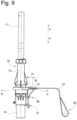
Fig. 8 eine perspektivische Darstellung der Lagervorrichtung, wobei sich die Haltestange in der Entnahmeposition und die Verriegelungsvorrichtung in der Löseposition befinden, -
Fig. 9 eine Seitenansicht der Lagervorrichtung gemäßFig. 8 , und -
Fig. 10 eine Längsschnittdarstellung der Lagervorrichtung gemäßFig. 9 . - Die Lagervorrichtung insgesamt ist in den Fig. mit dem Bezugszeichen 10 bezeichnet.
- Die Lagervorrichtung 10 umfasst gemäß
Fig. 1 eine Haltestange 11, ein Führungsteil 12, und eine Verriegelungsvorrichtung 15, die mittels einer Betätigungsvorrichtung 16 für die Verriegelungsvorrichtung 15 betätigbar ist. - Die Haltestange 11 ist im vorliegenden Ausführungsbeispiel eine Einzelhaltestange. Ein nicht dargestelltes Kopfanlageteil ist z.B. an zwei Lagervorrichtungen 10 gelagert. Die Verriegelungsvorrichtung 15 kann lediglich bei einer der Lagervorrichtungen 10 oder alternativ bei beiden Lagervorrichtungen 10 vorgesehen sein.
- Die Haltestange 11 ist an einem oberen Endbereich 18 mit einer Befestigungsstruktur 17 versehen, mit welcher das Kopfanlageteil an der Haltestange befestigbar ist. In diesem Ausführungsbeispiel ist die Befestigungsstruktur 17 als Aussparung ausgebildet, wobei aber auch andere Befestigungsstrukturen einsetzbar sind.
- Ein unterer Endbereich 19 der Haltestange 11 ist in einer Führungsaussparung 20 des Führungsteils 12 aufgenommen. Das Führungsteil 12 ist in diesem Ausführungsbeispiel zweiteilig ausgebildet und weist ein Führungsoberteil 13 sowie ein Führungsunterteil 14 auf. Die Zweiteiligkeit erleichtert die Montage des Führungsteils 12. An einem oberen Endbereich 21 weist das Führungsoberteil 13 eine ringförmige Verdickung 22 auf, welche der Aufnahme eines Gleitlagers dient.
- An einem unteren Endbereich 23 des Führungsoberteils 13 sind erste Führungsmittel 24 ausgebildet, die mit zweiten Führungsmitteln 25 des Führungsunterteils 14 zusammenwirken, um das Führungsoberteil 13 in einen Rastsitz des Führungsunterteils zu bewegen und diese Teile auf diese Weise miteinander zu verbinden.
- Die ersten Führungsmittel 24 sind in dem Ausführungsbeispiel von Stegen 26a und 26b gebildet, wobei der Steg 26a in Nuten 27a und und der Steg 26b in Nuten 27b eingreift. Wenn der Rastsitz gemäß
Fig. 1 erreicht ist, verrastet eine Hakenstruktur 28 des Führungsunterteils 14 mit einer Aussparung 29 des Führungsoberteils 13. Im verrasteten Zustand sind das Führungsoberteil 13 und das Führungsunterteil 14 nicht zueinander relativbewegbar. - An dem Führungsoberteil 13 ist eine Lagerstruktur 30 ausgebildet, welche der Gleitführung eines Riegelhalters 31 dient. Die Lagerstruktur 30 umfasst eine Aussparung 32, an deren Innenflächen der Riegelhalter 31 derart geführt ist, dass er lediglich Freiheitsgrade in Richtung y1 und y2 aufweist. Der Riegelhalter ist im vorliegenden Beispiel in die Richtungen y1 und y2 zwischen einer Riegelposition und einer Löseposition bewegbar, was weiter unten genauer erläutert wird. Die Bewegung des Riegelhalters 31 verläuft etwa rechtwinklig zu einer Längsmittelachse m1 der Führungsaussparung 20. In dem unteren Endbereich 19 der Haltestange 11 verläuft eine Längsmittelachse m2 der Haltestange 11 etwa parallel zu der Längsmittelachse m1, wenn sich die Haltestange in der Riegelstellung oder der Entnahmestellung befindet.
- Die Verriegelungsvorrichtung 15 umfasst die Betätigungsvorrichtung 16 mit welcher dier Verriegelungsvorrichtung 15 zwischen der Riegelposition und der Löseposition verstellbar ist. In dem vorliegenden Beispiel wird die Verriegelungsvorrichtung 15 manuell an einer Betätigung 63 betätigt. Alternativ könnte aber ebenso eine motorische Betätigung vorgesehen sein.
- Die Betätigungsvorrichtung 16 umfasst ein Band 33, wobei das Band 33 an einem Endbereich 34 manuell betätigt wird. An dem Endbereich 34 ist in dem vorliegenden Beispiel eine Schlaufe ausgebildet, an welcher eine Zugkraft F1 auf das Band 33 aufgebracht werden kann. Alternativ zu der Schlaufe könnte auch eine andere Betätigung 63 vorgesehen sein, wie z.B. ein Griff oder z.B. alternativ oder zusätzlich eine Verbindung mit einem motorischen Antrieb.
- Ein Endbereich 35 des Bandes 33 ist mittels einer Halterung 37 an einem Ausstoßer 36 befestigt, auf den weiter unten eingegangen wird.
- Das Band 33 verläuft von der Halterung 37 etwa parallel zu der Längsmittelachse m1 etwa in Richtung der z-Achse, wobei es von einer Führung 38 des Führungsteils 12 außen an dem Führungsteil 12 geführt wird. Das Band 33 liegt an einer Widerlagerfläche 57 eines Widerlagers des Riegelhalters 31 an, und wird an der Widerlagerfläche, die in
Fig. 1 nicht erkennbar ist, in eine Richtung parallel zu der Achse y etwa rechtwinklig umgelenkt. Die Widerlagerfläche 57 bildet ein Gleitlager, an welchem das Band 33 vorbeigleitet, wenn es sich relativ zu dem Riegelhalter 31 bewegt. Alternativ könnte aber auch eine Rolle vorgesehen sein, über welche das Band 33 gleitet. Im vorliegenden Ausführungsbeispiel ist die Widerlagerfläche 57 von der Laibung einer einer Aussparung 39 des Riegelhalters 31 gebildet. - Die Widerlagerfläche stellt z.B. eine flaschenzugartige Führung dar, so dass an der Widerlagerfläche eine Kraft F2 aufgenommen wird, wenn an dem Endbereich 34 eine Kraft F1 auf das Band wirkt. Die Kraft F2 an der Widerlagerfläche 57 ist z.B. doppelt so groß wie eine Kraft F1, die an der Halterung 37 und auch an dem Endbereich 34 des Bandes anliegt. Das Band kann sich relativ zu der Widerlagerfläche 57 bewegen.
-
Fig. 2 ist eine Seitenansicht der Vorrichtung etwa gemäß Ansichtspfeil B inFig. 1 . - In der Schnittdarstellung gemäß
Fig. 3 ist erkennbar, dass das Führungsteil 12 Gleitlager 40 und 41 aufweist, die voneinander beabstandet an dem Führungsteil gehalten sind und derart in einen Führungsraum 42 des Führungsteils 12 radial hineinragen, dass sie die Haltestange 11 bei der Montage in Richtung z1 und der Demontage in Richtung z2 gleitführen können. - In einem Aufnahmeraum 43 des Führungsteils 12 ist eine Feder 44 aufgenommen, welche sich mit einem Federende 45 an einer Bodenfläche 46 des Führungsteils abstützt. Ein Federende 47 steht mit einer Kontaktfläche 48 des Ausstoßers 36 in Kontakt, derart, dass die Feder 44 den Ausstoßer 36 in Richtung z1 belasten kann, wenn sie unter Spannung steht. Der Ausstoßer 36 ist derart in dem Führungsteil 12 geführt, dass er sich lediglich in die Richtungen z1 und z2 bewegen kann. Gemäß
Fig. 3 ist die Feder 44 gespannt. Der Ausstoßer 44 weist eine Betätigungsfläche 49 auf, die mit einer Gegenfläche 50 eines Ansatzteils 51 in Kontakt steht, welches fest mit dem unteren Endbereich 19 der Haltestange 11 verbunden ist. - Das Ansatzteil 51 umfasst eine Schrägfläche 59, die derart ausgebildet ist, dass beim Einstecken der Haltestange 11 in Richtung z1 in die Führungsaussparung 20 des Führungsteils 12 eine Kraft auf den in der Bewegungsbahn befindlichen Riegel in Richtung y1 ausgeübt werden kann, so dass dieser sich in Richtung y1 aus der Bewegungsbahn herausbewegt. Im vorliegenden Beispiel ist an dem Ansatzteil 51 eine konusformige umlaufende Schräge ausgebildet. Wie in
Fig. 3 zu erkennen ist, bildet das Ansatzteil 51 eine Verlängerung der Haltestange 11. - In den
Fig. 3 und4 ist zu sehen, dass in der dargestellten Arretierposition der Haltestange 11 das Ansatzteil 51 in einem Sitz 52 des Führungsteils 12 angeordnet ist. Der Sitz 52 wird von einer Innenfläche 53 des Führungsteils 12, z.B. des Führungsunterteils 14 ausgebildet. - Gemäß
Fig. 4 ist an dem Riegelhalter 31 ein separater Riegel 54 gehalten. Der Riegel 54 ist z.B. von einem Draht gebildet, der an dem Riegel 54 befestigt, z.B. im Kunststoffspritzgießverfahren eingespritzt ist. Alternativ kann der Riegel aber auch von einer Fläche des Riegelhalters 31 gebildet sein, d.h. kein gesondertes Teil sein. Der Riegel 54 steht gemäßFig. 4 in Eingriff mit einer Aussparung 55 der Haltestange 11. Die Aussparung 55 befindet sich an der Mantelfläche 56 der Haltestange 11. - Der Riegel 54 greift etwa radial zu der Längsmittelachse m1 in die Aussparung 55 ein, derart, dass er eine Bewegung der Haltestange 11 in die Richtungen z1 und z2 verhindert. Auch in andere Raumrichtungen kann sich die Haltestange 11 in der Arretierposition nicht bewegen. Die dabei von dem Riegel 54 aufgenommenen Kräfte werden auf den Riegelhalter 31 übertragen und von diesem weiter auf das Führungsteil 12 übertragen.
- Die Funktion der Lagervorrichtung 10 wird nachstehend erläutert. Wenn sich die Haltestange 11 in der Arretierstellung in dem Führungsteil befindet und der Riegel 54 in der Riegelposition der Verriegelungsvorrichtung 15 in Eingriff mit der Aussparung 55 der Haltestange 11 ist, wird die Kraft der Feder 44 über den Ausstoßer 36 auf die Haltestange 11 übertragen und über den Riegelhalter 31 an die das Führungsteil 12 abgegeben.
- Eine zusätzlich auf das Band 33 ausgeübte Kraft F1 wird auf den Ausstoßer 36 übertragen, so dass dieser von einer zusätzlich zu der Federkraft einwirkenden Kraft F1 in Richtung z1 belastet wird. Solange der Riegel 54 in Eingriff mit der Aussparung 55 ist, wird auch diese Kraft von dem Führungsteil 12 aufgenommen.
- An der in
Fig. 4 erkennbaren Widerlagerfläche 57 des Riegelhalters 31 wirkt bei einer Betätigungskraft F1 auf das Band 33 eine Kraft F2 in Richtung y1. Die Kraft F2 bewirkt eine Bewegung des Riegelhalters 31 in Richtung y1, wobei sich der Riegel 54 außer Eingriff mit der Aussparung 55 bewegt. Die Verriegelungsvorrichtung ist damit von der Riegelposition in die Löseposition verstellt worden (siehe dieFig. 5 bis 7 ). Die Flächen 61 und 62 sind um eine Strecke s1 voneinander beabstandet. - Da die Haltestange 11 nun nicht mehr in der Arretierposition verriegelt ist, kann diese unter Einwirkung der Federkraft sowie der Kraft F1 von dem Ausstoßer 36 in eine Entnahmeposition bewegt werden, die in den
Fig. 8 bis 10 dargestellt ist. Der Ausstoßer 36 bewegt sich dabei von einer ersten Position gemäß derFig. 3 und4 in eine zweite Position gemäßFig. 10 . Die Flächen 61 und 62 sind um die Strecke s2 voneinander beabstandet. - In der Entnahmeposition kann bei nachlassender Kraft auf das Band 33 die Haltestange 11 nicht wiederverriegelt werden. Auch wenn sich der Riegelhalter 31 in Richtung y2 bewegt, schlägt der Riegel 54 an eine Außenfläche 58 des Ansatzteils 51 der Haltestange 11 an, da sich der Riegel 54 und die Aussparung 55 in unterschiedlichen Positionen bezüglich der Z-Achse befinden.
- Aus der Entnahmeposition kann die Haltestange 11 durch eine Bewegung in Richtung z1 aus dem Führungsraum 42 entfernt werden. Der von Federn 60 (siehe
Fig. 10 ) in Richtung y2 belastete Riegelhalter 31 wird dann in Richtung y2 bewegt, bis Halteflächen 61 des Riegelhalters 31 an einer Gegenfläche 62 des Führungsteils 12 anliegen. - Die Montage der Haltestange 11 erfolgt, indem die Haltestange 11 in Montagerichtung z2 in den Führungsraum 42 bewegt wird, bis die Schrägfläche 59 des Ansatzteils 51 mit dem Riegel 54 oder dem Riegelhalter 31 in Kontakt gerät. Bei weiterer Bewegung in Richtung z2 wird eine Kraft in Richtung y1 auf den Riegelhalter 31 ausgeübt, welche den Riegelhalter 31 in Richtung y2 aus der Bewegungsbahn der Haltestange 11 bewegt. Die Haltestange 11 kann daher weiter in Richtung z2 bewegt werden, bis das Ansatzteil 51 in dem Sitz 52 angeordnet ist. Die Haltestange 11 befindet sich dann wieder in der Arretierposition. In der Arretierposition befinden sich der Riegel 54 und die Aussparung 55 auf dem gleichen Niveau bezüglich der Z-Achse, so dass sich der von Federn 60 in Richtung y2 belastete Riegelhalter 31 in Richtung y2 bewegen kann, wobei sich der Riegel 54 in Eingriff mit der Aussparung 55 bewegt.
Claims (15)
- Lagervorrichtung (10) für eine Kopfstütze umfassend ein Führungsteil (12) mit welchem die Haltestange (11) der Kopfstütze an einem Fahrzeugsitz lagerbar ist und mittels einer Verriegelungsvorrichtung (15) in einer Arretierstellung relativ zu dem Führungsteil (12) lösbar festlegbar ist, wobei die Verriegelungsvorrichtung (15) einen zwischen einer Riegelposition und einer Löseposition bewegbaren Riegel (54) umfasst, welcher dem Führungsteil (12) zugeordnet ist und wenigstens eine Aussparung (55) umfasst, welche der Haltestange (11) zugeordnet ist, dadurch gekennzeichnet, dass eine Betätigungsvorrichtung (16) der Verriegelungsvorrichtung (15) eine Kraftübertragungs-Verbindung in Form eines Bandes (33), insbesondere eines flaschenzugartig geführten Bandes (33), umfasst, derart, dass bei einer Verstellung der Betätigungsvorrichtung der Riegel (54) durch eine resultierende Betätigungskraft in die Löseposition verstellbar ist.
- Lagervorrichtung nach einem der vorangehenden Ansprüche, dadurch gekennzeichnet, dass dass Band (33) mit einem an dem Führungsteil (12) geführten Ausstoßer (36) für die Haltestange (11) in Verbindung steht, derart, dass eine weitere resultierende Betätigungskraft auf den Ausstoßer (36) wirkt und diesen von einer ersten Position in eine zweite Position belastet.
- Lagervorrichtung nach einem der vorangehenden Ansprüche, dadurch gekennzeichnet, dass das Band (33) einen Betätigungsbereich umfasst, welcher mit einem Widerlager des Riegels (54) zusammenwirkt, derart, dass bei einer Zugkraft auf das Band (33) eine Kraft auf das Widerlager ausgeübt wird, welche den Riegel (54) in die Löseposition verstellt.
- Lagervorrichtung nach einem der vorangehenden Ansprüche, dadurch gekennzeichnet, dass in der Riegelposition das Band (33) an dem Widerlager von einer ersten Erstreckungs-Richtung (y1, y2) in eine zweite Erstreckungs-Richtung (z1, z2) umgelenkt wird.
- Lagervorrichtung nach einem der vorangehenden Ansprüche, dadurch gekennzeichnet, dass der Betätigungsbereich zwischen einem ersten Endbereich (34) und einem zweiten Endbereich (35) des Bandes (33) ausgebildet ist.
- Lagervorrichtung nach einem der vorangehenden Ansprüche, dadurch gekennzeichnet, dass ein Endbereich (34) des Bandes (33) eine motorische oder manuelle Betätigung (63) bildet und der andere Endbereich (35) eine Halterung an dem Ausstoßer (36) bildet.
- Lagervorrichtung nach einem der vorangehenden Ansprüche, dadurch gekennzeichnet, dass der Riegel (54) einem zwischen der Riegelposition und der Löseposition bewegbar geführten Riegelhalter (31) zugeordnet ist.
- Lagervorrichtung nach Anspruch 7, dadurch gekennzeichnet, dass der Riegelhalter (31) in einer Aussparung (32) des Führungsteils (12) geführt ist.
- Lagervorrichtung nach einem der vorangehenden Ansprüche, dadurch gekennzeichnet, dass der Riegel (54) in der Riegelposition mit einem ersten Anschlag und in der Löseposition mit einem zweiten Anschlag in Kontakt steht.
- Lagervorrichtung nach einem der vorangehenden Ansprüche, dadurch gekennzeichnet, dass der Riegel (54) translatorisch verschiebbar oder drehbar gelagert ist.
- Lagervorrichtung nach einem der vorangehenden Ansprüche, dadurch gekennzeichnet, dass der Riegel (54) von wenigstens einer Feder (60) in die Riegelposition belastet ist.
- Lagervorrichtung nach einem der vorangehenden Ansprüche, dadurch gekennzeichnet, dass der Ausstoßer (36) translatorisch oder rotatorisch bewegbar gelagert ist.
- Lagervorrichtung nach einem der vorangehenden Ansprüche, dadurch gekennzeichnet, dass der Ausstoßer (36) von wenigstens einer Feder (44) in Ausstoßrichtung belastet ist.
- Lagervorrichtung nach einem der vorangehenden Ansprüche, dadurch gekennzeichnet, dass die Haltestange (11) endseitig eine Konusstruktur aufweist.
- Lagervorrichtung nach Anspruch 14, dadurch gekennzeichnet, dass die Konusstruktur einem Ansatzteil (51), welches insbesondere als Kunststoffteil ausgebildet ist, zugeordnet ist und welches mit der Haltestange (11) verbunden ist.
Applications Claiming Priority (1)
| Application Number | Priority Date | Filing Date | Title |
|---|---|---|---|
| DE102020122353.6A DE102020122353B4 (de) | 2020-08-26 | 2020-08-26 | Lagervorrichtung für eine Kopfstütze |
Publications (2)
| Publication Number | Publication Date |
|---|---|
| EP3967549A1 EP3967549A1 (de) | 2022-03-16 |
| EP3967549B1 true EP3967549B1 (de) | 2024-07-24 |
Family
ID=77398451
Family Applications (1)
| Application Number | Title | Priority Date | Filing Date |
|---|---|---|---|
| EP21191877.6A Active EP3967549B1 (de) | 2020-08-26 | 2021-08-18 | Lagervorrichtung für eine kopfstütze |
Country Status (2)
| Country | Link |
|---|---|
| EP (1) | EP3967549B1 (de) |
| DE (1) | DE102020122353B4 (de) |
Family Cites Families (4)
| Publication number | Priority date | Publication date | Assignee | Title |
|---|---|---|---|---|
| DE2138078A1 (de) | 1971-07-30 | 1973-02-08 | Daimler Benz Ag | Endlagesicherung fuer eine kopfstuetze |
| DE19803182C2 (de) | 1998-01-28 | 2000-02-17 | Grammer Ag | Fahrzeugsitz |
| DE102007022623B4 (de) | 2007-05-15 | 2010-08-19 | Lear Corporation, Southfield | Fahrzeugsitz mit einer einstellbaren Kopfstütze |
| DE112011100271B4 (de) * | 2010-01-18 | 2014-09-18 | Lear Corporation | Sitzbaugruppe |
-
2020
- 2020-08-26 DE DE102020122353.6A patent/DE102020122353B4/de active Active
-
2021
- 2021-08-18 EP EP21191877.6A patent/EP3967549B1/de active Active
Also Published As
| Publication number | Publication date |
|---|---|
| DE102020122353B4 (de) | 2026-05-13 |
| EP3967549A1 (de) | 2022-03-16 |
| DE102020122353A1 (de) | 2022-03-03 |
Similar Documents
| Publication | Publication Date | Title |
|---|---|---|
| DE3930171C2 (de) | Überrollschutz | |
| DE19711006A1 (de) | Kopfstütze für Kraftfahrzeugsitz | |
| EP2879905B1 (de) | Verstellbarer fahrzeugsitz | |
| EP0525837B1 (de) | Vorrichtung zum Straffen eines Sicherheitsgurtes in einem Fahrzeug, insbesondere Kraftfahrzeug | |
| EP3566933B1 (de) | Gliederkette und rahmenschlosssystem für ein zweirad | |
| DE60312340T2 (de) | Im boden verstaubare sitzanordnung mit querverschiebung | |
| EP3299216A1 (de) | Armlehne | |
| DE102018107492A1 (de) | Verbesserter Klappmechanismus für einen Elektroroller | |
| DE102015012411B4 (de) | Kopfstütze | |
| DE102019201809B4 (de) | Armlehnenanordnung für einen Kraftfahrzeuginnenraum | |
| EP1809441B1 (de) | Spann- oder greifvorrichtung insbesondere linear- oder zentrischgreifer | |
| EP3356696B1 (de) | Schnell lösbare rastanordnung für ein bauteil der hebe-, zurr- oder anschlagtechnik | |
| DE102014001980B3 (de) | Kopfstütze für Fahrzeugsitze | |
| DE69002172T2 (de) | Werkzeugspannvorrichtung. | |
| DE2507848C3 (de) | Schwenkbare Armstütze | |
| DE202021100671U1 (de) | Kopfstütze | |
| DE102008011560B3 (de) | Verriegelungsvorrichtung, insbesondere für eine Kopfstütze für Fahrzeugsitze | |
| DE102020122353B4 (de) | Lagervorrichtung für eine Kopfstütze | |
| DE102020131548A1 (de) | Tragstange, Haltevorrichtung und Verfahren zur Herstellung | |
| EP3819513B1 (de) | Geitlager, ausstattungsvorrichtung mit wenigstens einem gleitlager und ausstattungsvorrichtung mit wenigstens einem drehbaren aufgenommenen lager | |
| EP3620082B1 (de) | Arretierungsvorrichtung für ein verschwenkbares sitzmöbel, sitzmöbel | |
| DE3205133C2 (de) | ||
| DE102005005826B4 (de) | Kopfstütze | |
| DE1079475B (de) | Nach vorn schwenkbare, mit einer Feststellvorrichtung versehene Rueckenlehne, insbesondere fuer die Vordersitze von Kraftfahrzeugen | |
| DE102016109715B4 (de) | Verriegelungseinrichtung für Kraftfahrzeuge |
Legal Events
| Date | Code | Title | Description |
|---|---|---|---|
| PUAI | Public reference made under article 153(3) epc to a published international application that has entered the european phase |
Free format text: ORIGINAL CODE: 0009012 |
|
| STAA | Information on the status of an ep patent application or granted ep patent |
Free format text: STATUS: THE APPLICATION HAS BEEN PUBLISHED |
|
| AK | Designated contracting states |
Kind code of ref document: A1 Designated state(s): AL AT BE BG CH CY CZ DE DK EE ES FI FR GB GR HR HU IE IS IT LI LT LU LV MC MK MT NL NO PL PT RO RS SE SI SK SM TR |
|
| STAA | Information on the status of an ep patent application or granted ep patent |
Free format text: STATUS: REQUEST FOR EXAMINATION WAS MADE |
|
| 17P | Request for examination filed |
Effective date: 20220505 |
|
| RBV | Designated contracting states (corrected) |
Designated state(s): AL AT BE BG CH CY CZ DE DK EE ES FI FR GB GR HR HU IE IS IT LI LT LU LV MC MK MT NL NO PL PT RO RS SE SI SK SM TR |
|
| STAA | Information on the status of an ep patent application or granted ep patent |
Free format text: STATUS: EXAMINATION IS IN PROGRESS |
|
| 17Q | First examination report despatched |
Effective date: 20220915 |
|
| GRAP | Despatch of communication of intention to grant a patent |
Free format text: ORIGINAL CODE: EPIDOSNIGR1 |
|
| STAA | Information on the status of an ep patent application or granted ep patent |
Free format text: STATUS: GRANT OF PATENT IS INTENDED |
|
| INTG | Intention to grant announced |
Effective date: 20240325 |
|
| GRAS | Grant fee paid |
Free format text: ORIGINAL CODE: EPIDOSNIGR3 |
|
| GRAA | (expected) grant |
Free format text: ORIGINAL CODE: 0009210 |
|
| STAA | Information on the status of an ep patent application or granted ep patent |
Free format text: STATUS: THE PATENT HAS BEEN GRANTED |
|
| AK | Designated contracting states |
Kind code of ref document: B1 Designated state(s): AL AT BE BG CH CY CZ DE DK EE ES FI FR GB GR HR HU IE IS IT LI LT LU LV MC MK MT NL NO PL PT RO RS SE SI SK SM TR |
|
| P01 | Opt-out of the competence of the unified patent court (upc) registered |
Free format text: CASE NUMBER: APP_36619/2024 Effective date: 20240619 |
|
| REG | Reference to a national code |
Ref country code: GB Ref legal event code: FG4D Free format text: NOT ENGLISH |
|
| REG | Reference to a national code |
Ref country code: CH Ref legal event code: EP |
|
| REG | Reference to a national code |
Ref country code: DE Ref legal event code: R096 Ref document number: 502021004472 Country of ref document: DE |
|
| REG | Reference to a national code |
Ref country code: IE Ref legal event code: FG4D Free format text: LANGUAGE OF EP DOCUMENT: GERMAN |
|
| REG | Reference to a national code |
Ref country code: LT Ref legal event code: MG9D |
|
| REG | Reference to a national code |
Ref country code: NL Ref legal event code: MP Effective date: 20240724 |
|
| PG25 | Lapsed in a contracting state [announced via postgrant information from national office to epo] |
Ref country code: PT Free format text: LAPSE BECAUSE OF FAILURE TO SUBMIT A TRANSLATION OF THE DESCRIPTION OR TO PAY THE FEE WITHIN THE PRESCRIBED TIME-LIMIT Effective date: 20241125 |
|
| PG25 | Lapsed in a contracting state [announced via postgrant information from national office to epo] |
Ref country code: NL Free format text: LAPSE BECAUSE OF FAILURE TO SUBMIT A TRANSLATION OF THE DESCRIPTION OR TO PAY THE FEE WITHIN THE PRESCRIBED TIME-LIMIT Effective date: 20240724 |
|
| PG25 | Lapsed in a contracting state [announced via postgrant information from national office to epo] |
Ref country code: PT Free format text: LAPSE BECAUSE OF FAILURE TO SUBMIT A TRANSLATION OF THE DESCRIPTION OR TO PAY THE FEE WITHIN THE PRESCRIBED TIME-LIMIT Effective date: 20241125 Ref country code: NL Free format text: LAPSE BECAUSE OF FAILURE TO SUBMIT A TRANSLATION OF THE DESCRIPTION OR TO PAY THE FEE WITHIN THE PRESCRIBED TIME-LIMIT Effective date: 20240724 |
|
| PG25 | Lapsed in a contracting state [announced via postgrant information from national office to epo] |
Ref country code: NO Free format text: LAPSE BECAUSE OF FAILURE TO SUBMIT A TRANSLATION OF THE DESCRIPTION OR TO PAY THE FEE WITHIN THE PRESCRIBED TIME-LIMIT Effective date: 20241024 |
|
| PG25 | Lapsed in a contracting state [announced via postgrant information from national office to epo] |
Ref country code: FI Free format text: LAPSE BECAUSE OF FAILURE TO SUBMIT A TRANSLATION OF THE DESCRIPTION OR TO PAY THE FEE WITHIN THE PRESCRIBED TIME-LIMIT Effective date: 20240724 Ref country code: GR Free format text: LAPSE BECAUSE OF FAILURE TO SUBMIT A TRANSLATION OF THE DESCRIPTION OR TO PAY THE FEE WITHIN THE PRESCRIBED TIME-LIMIT Effective date: 20241025 Ref country code: PL Free format text: LAPSE BECAUSE OF FAILURE TO SUBMIT A TRANSLATION OF THE DESCRIPTION OR TO PAY THE FEE WITHIN THE PRESCRIBED TIME-LIMIT Effective date: 20240724 |
|
| PG25 | Lapsed in a contracting state [announced via postgrant information from national office to epo] |
Ref country code: BG Free format text: LAPSE BECAUSE OF FAILURE TO SUBMIT A TRANSLATION OF THE DESCRIPTION OR TO PAY THE FEE WITHIN THE PRESCRIBED TIME-LIMIT Effective date: 20240724 |
|
| PG25 | Lapsed in a contracting state [announced via postgrant information from national office to epo] |
Ref country code: LV Free format text: LAPSE BECAUSE OF FAILURE TO SUBMIT A TRANSLATION OF THE DESCRIPTION OR TO PAY THE FEE WITHIN THE PRESCRIBED TIME-LIMIT Effective date: 20240724 |
|
| PG25 | Lapsed in a contracting state [announced via postgrant information from national office to epo] |
Ref country code: IS Free format text: LAPSE BECAUSE OF FAILURE TO SUBMIT A TRANSLATION OF THE DESCRIPTION OR TO PAY THE FEE WITHIN THE PRESCRIBED TIME-LIMIT Effective date: 20241124 |
|
| PG25 | Lapsed in a contracting state [announced via postgrant information from national office to epo] |
Ref country code: HR Free format text: LAPSE BECAUSE OF FAILURE TO SUBMIT A TRANSLATION OF THE DESCRIPTION OR TO PAY THE FEE WITHIN THE PRESCRIBED TIME-LIMIT Effective date: 20240724 |
|
| PG25 | Lapsed in a contracting state [announced via postgrant information from national office to epo] |
Ref country code: ES Free format text: LAPSE BECAUSE OF FAILURE TO SUBMIT A TRANSLATION OF THE DESCRIPTION OR TO PAY THE FEE WITHIN THE PRESCRIBED TIME-LIMIT Effective date: 20240724 Ref country code: RS Free format text: LAPSE BECAUSE OF FAILURE TO SUBMIT A TRANSLATION OF THE DESCRIPTION OR TO PAY THE FEE WITHIN THE PRESCRIBED TIME-LIMIT Effective date: 20241024 |
|
| PG25 | Lapsed in a contracting state [announced via postgrant information from national office to epo] |
Ref country code: RS Free format text: LAPSE BECAUSE OF FAILURE TO SUBMIT A TRANSLATION OF THE DESCRIPTION OR TO PAY THE FEE WITHIN THE PRESCRIBED TIME-LIMIT Effective date: 20241024 Ref country code: PL Free format text: LAPSE BECAUSE OF FAILURE TO SUBMIT A TRANSLATION OF THE DESCRIPTION OR TO PAY THE FEE WITHIN THE PRESCRIBED TIME-LIMIT Effective date: 20240724 Ref country code: NO Free format text: LAPSE BECAUSE OF FAILURE TO SUBMIT A TRANSLATION OF THE DESCRIPTION OR TO PAY THE FEE WITHIN THE PRESCRIBED TIME-LIMIT Effective date: 20241024 Ref country code: LV Free format text: LAPSE BECAUSE OF FAILURE TO SUBMIT A TRANSLATION OF THE DESCRIPTION OR TO PAY THE FEE WITHIN THE PRESCRIBED TIME-LIMIT Effective date: 20240724 Ref country code: IS Free format text: LAPSE BECAUSE OF FAILURE TO SUBMIT A TRANSLATION OF THE DESCRIPTION OR TO PAY THE FEE WITHIN THE PRESCRIBED TIME-LIMIT Effective date: 20241124 Ref country code: HR Free format text: LAPSE BECAUSE OF FAILURE TO SUBMIT A TRANSLATION OF THE DESCRIPTION OR TO PAY THE FEE WITHIN THE PRESCRIBED TIME-LIMIT Effective date: 20240724 Ref country code: GR Free format text: LAPSE BECAUSE OF FAILURE TO SUBMIT A TRANSLATION OF THE DESCRIPTION OR TO PAY THE FEE WITHIN THE PRESCRIBED TIME-LIMIT Effective date: 20241025 Ref country code: FI Free format text: LAPSE BECAUSE OF FAILURE TO SUBMIT A TRANSLATION OF THE DESCRIPTION OR TO PAY THE FEE WITHIN THE PRESCRIBED TIME-LIMIT Effective date: 20240724 Ref country code: ES Free format text: LAPSE BECAUSE OF FAILURE TO SUBMIT A TRANSLATION OF THE DESCRIPTION OR TO PAY THE FEE WITHIN THE PRESCRIBED TIME-LIMIT Effective date: 20240724 Ref country code: BG Free format text: LAPSE BECAUSE OF FAILURE TO SUBMIT A TRANSLATION OF THE DESCRIPTION OR TO PAY THE FEE WITHIN THE PRESCRIBED TIME-LIMIT Effective date: 20240724 |
|
| REG | Reference to a national code |
Ref country code: CH Ref legal event code: PL |
|
| PG25 | Lapsed in a contracting state [announced via postgrant information from national office to epo] |
Ref country code: RO Free format text: LAPSE BECAUSE OF FAILURE TO SUBMIT A TRANSLATION OF THE DESCRIPTION OR TO PAY THE FEE WITHIN THE PRESCRIBED TIME-LIMIT Effective date: 20240724 Ref country code: SM Free format text: LAPSE BECAUSE OF FAILURE TO SUBMIT A TRANSLATION OF THE DESCRIPTION OR TO PAY THE FEE WITHIN THE PRESCRIBED TIME-LIMIT Effective date: 20240724 Ref country code: DK Free format text: LAPSE BECAUSE OF FAILURE TO SUBMIT A TRANSLATION OF THE DESCRIPTION OR TO PAY THE FEE WITHIN THE PRESCRIBED TIME-LIMIT Effective date: 20240724 |
|
| PG25 | Lapsed in a contracting state [announced via postgrant information from national office to epo] |
Ref country code: LU Free format text: LAPSE BECAUSE OF NON-PAYMENT OF DUE FEES Effective date: 20240818 |
|
| PG25 | Lapsed in a contracting state [announced via postgrant information from national office to epo] |
Ref country code: MC Free format text: LAPSE BECAUSE OF FAILURE TO SUBMIT A TRANSLATION OF THE DESCRIPTION OR TO PAY THE FEE WITHIN THE PRESCRIBED TIME-LIMIT Effective date: 20240724 Ref country code: CH Free format text: LAPSE BECAUSE OF NON-PAYMENT OF DUE FEES Effective date: 20240831 Ref country code: EE Free format text: LAPSE BECAUSE OF FAILURE TO SUBMIT A TRANSLATION OF THE DESCRIPTION OR TO PAY THE FEE WITHIN THE PRESCRIBED TIME-LIMIT Effective date: 20240724 |
|
| PG25 | Lapsed in a contracting state [announced via postgrant information from national office to epo] |
Ref country code: CZ Free format text: LAPSE BECAUSE OF FAILURE TO SUBMIT A TRANSLATION OF THE DESCRIPTION OR TO PAY THE FEE WITHIN THE PRESCRIBED TIME-LIMIT Effective date: 20240724 |
|
| REG | Reference to a national code |
Ref country code: DE Ref legal event code: R097 Ref document number: 502021004472 Country of ref document: DE |
|
| PG25 | Lapsed in a contracting state [announced via postgrant information from national office to epo] |
Ref country code: IT Free format text: LAPSE BECAUSE OF FAILURE TO SUBMIT A TRANSLATION OF THE DESCRIPTION OR TO PAY THE FEE WITHIN THE PRESCRIBED TIME-LIMIT Effective date: 20240724 Ref country code: SK Free format text: LAPSE BECAUSE OF FAILURE TO SUBMIT A TRANSLATION OF THE DESCRIPTION OR TO PAY THE FEE WITHIN THE PRESCRIBED TIME-LIMIT Effective date: 20240724 |
|
| PLBE | No opposition filed within time limit |
Free format text: ORIGINAL CODE: 0009261 |
|
| STAA | Information on the status of an ep patent application or granted ep patent |
Free format text: STATUS: NO OPPOSITION FILED WITHIN TIME LIMIT |
|
| REG | Reference to a national code |
Ref country code: BE Ref legal event code: MM Effective date: 20240831 |
|
| 26N | No opposition filed |
Effective date: 20250425 |
|
| PG25 | Lapsed in a contracting state [announced via postgrant information from national office to epo] |
Ref country code: BE Free format text: LAPSE BECAUSE OF NON-PAYMENT OF DUE FEES Effective date: 20240831 |
|
| PG25 | Lapsed in a contracting state [announced via postgrant information from national office to epo] |
Ref country code: IE Free format text: LAPSE BECAUSE OF NON-PAYMENT OF DUE FEES Effective date: 20240818 |
|
| PG25 | Lapsed in a contracting state [announced via postgrant information from national office to epo] |
Ref country code: SE Free format text: LAPSE BECAUSE OF FAILURE TO SUBMIT A TRANSLATION OF THE DESCRIPTION OR TO PAY THE FEE WITHIN THE PRESCRIBED TIME-LIMIT Effective date: 20240724 |
|
| PGFP | Annual fee paid to national office [announced via postgrant information from national office to epo] |
Ref country code: DE Payment date: 20250819 Year of fee payment: 5 |
|
| PGFP | Annual fee paid to national office [announced via postgrant information from national office to epo] |
Ref country code: AT Payment date: 20251020 Year of fee payment: 5 Ref country code: FR Payment date: 20250821 Year of fee payment: 5 |
|
| PG25 | Lapsed in a contracting state [announced via postgrant information from national office to epo] |
Ref country code: CY Free format text: LAPSE BECAUSE OF FAILURE TO SUBMIT A TRANSLATION OF THE DESCRIPTION OR TO PAY THE FEE WITHIN THE PRESCRIBED TIME-LIMIT; INVALID AB INITIO Effective date: 20210818 |
|
| PG25 | Lapsed in a contracting state [announced via postgrant information from national office to epo] |
Ref country code: HU Free format text: LAPSE BECAUSE OF FAILURE TO SUBMIT A TRANSLATION OF THE DESCRIPTION OR TO PAY THE FEE WITHIN THE PRESCRIBED TIME-LIMIT; INVALID AB INITIO Effective date: 20210818 |
|
| GBPC | Gb: european patent ceased through non-payment of renewal fee |
Effective date: 20250818 |