EP3967537A1 - Verfahren zur darstellung eines virtuellen elements - Google Patents
Verfahren zur darstellung eines virtuellen elements Download PDFInfo
- Publication number
- EP3967537A1 EP3967537A1 EP21191949.3A EP21191949A EP3967537A1 EP 3967537 A1 EP3967537 A1 EP 3967537A1 EP 21191949 A EP21191949 A EP 21191949A EP 3967537 A1 EP3967537 A1 EP 3967537A1
- Authority
- EP
- European Patent Office
- Prior art keywords
- virtual
- sub
- display area
- display device
- elements
- Prior art date
- Legal status (The legal status is an assumption and is not a legal conclusion. Google has not performed a legal analysis and makes no representation as to the accuracy of the status listed.)
- Granted
Links
Images

Classifications
-
- G—PHYSICS
- G02—OPTICS
- G02B—OPTICAL ELEMENTS, SYSTEMS OR APPARATUS
- G02B27/00—Optical systems or apparatus not provided for by any of the groups G02B1/00 - G02B26/00, G02B30/00
- G02B27/01—Head-up displays
- G02B27/0101—Head-up displays characterised by optical features
-
- B—PERFORMING OPERATIONS; TRANSPORTING
- B60—VEHICLES IN GENERAL
- B60K—ARRANGEMENT OR MOUNTING OF PROPULSION UNITS OR OF TRANSMISSIONS IN VEHICLES; ARRANGEMENT OR MOUNTING OF PLURAL DIVERSE PRIME-MOVERS IN VEHICLES; AUXILIARY DRIVES FOR VEHICLES; INSTRUMENTATION OR DASHBOARDS FOR VEHICLES; ARRANGEMENTS IN CONNECTION WITH COOLING, AIR INTAKE, GAS EXHAUST OR FUEL SUPPLY OF PROPULSION UNITS IN VEHICLES
- B60K35/00—Instruments specially adapted for vehicles; Arrangement of instruments in or on vehicles
- B60K35/20—Output arrangements, i.e. from vehicle to user, associated with vehicle functions or specially adapted therefor
- B60K35/21—Output arrangements, i.e. from vehicle to user, associated with vehicle functions or specially adapted therefor using visual output, e.g. blinking lights or matrix displays
- B60K35/213—Virtual instruments
-
- B—PERFORMING OPERATIONS; TRANSPORTING
- B60—VEHICLES IN GENERAL
- B60K—ARRANGEMENT OR MOUNTING OF PROPULSION UNITS OR OF TRANSMISSIONS IN VEHICLES; ARRANGEMENT OR MOUNTING OF PLURAL DIVERSE PRIME-MOVERS IN VEHICLES; AUXILIARY DRIVES FOR VEHICLES; INSTRUMENTATION OR DASHBOARDS FOR VEHICLES; ARRANGEMENTS IN CONNECTION WITH COOLING, AIR INTAKE, GAS EXHAUST OR FUEL SUPPLY OF PROPULSION UNITS IN VEHICLES
- B60K35/00—Instruments specially adapted for vehicles; Arrangement of instruments in or on vehicles
- B60K35/20—Output arrangements, i.e. from vehicle to user, associated with vehicle functions or specially adapted therefor
- B60K35/21—Output arrangements, i.e. from vehicle to user, associated with vehicle functions or specially adapted therefor using visual output, e.g. blinking lights or matrix displays
- B60K35/23—Head-up displays [HUD]
-
- B—PERFORMING OPERATIONS; TRANSPORTING
- B60—VEHICLES IN GENERAL
- B60K—ARRANGEMENT OR MOUNTING OF PROPULSION UNITS OR OF TRANSMISSIONS IN VEHICLES; ARRANGEMENT OR MOUNTING OF PLURAL DIVERSE PRIME-MOVERS IN VEHICLES; AUXILIARY DRIVES FOR VEHICLES; INSTRUMENTATION OR DASHBOARDS FOR VEHICLES; ARRANGEMENTS IN CONNECTION WITH COOLING, AIR INTAKE, GAS EXHAUST OR FUEL SUPPLY OF PROPULSION UNITS IN VEHICLES
- B60K35/00—Instruments specially adapted for vehicles; Arrangement of instruments in or on vehicles
- B60K35/20—Output arrangements, i.e. from vehicle to user, associated with vehicle functions or specially adapted therefor
- B60K35/28—Output arrangements, i.e. from vehicle to user, associated with vehicle functions or specially adapted therefor characterised by the type of the output information, e.g. video entertainment or vehicle dynamics information; characterised by the purpose of the output information, e.g. for attracting the attention of the driver
-
- B—PERFORMING OPERATIONS; TRANSPORTING
- B60—VEHICLES IN GENERAL
- B60K—ARRANGEMENT OR MOUNTING OF PROPULSION UNITS OR OF TRANSMISSIONS IN VEHICLES; ARRANGEMENT OR MOUNTING OF PLURAL DIVERSE PRIME-MOVERS IN VEHICLES; AUXILIARY DRIVES FOR VEHICLES; INSTRUMENTATION OR DASHBOARDS FOR VEHICLES; ARRANGEMENTS IN CONNECTION WITH COOLING, AIR INTAKE, GAS EXHAUST OR FUEL SUPPLY OF PROPULSION UNITS IN VEHICLES
- B60K35/00—Instruments specially adapted for vehicles; Arrangement of instruments in or on vehicles
- B60K35/65—Instruments specially adapted for specific vehicle types or users, e.g. for left- or right-hand drive
-
- B—PERFORMING OPERATIONS; TRANSPORTING
- B60—VEHICLES IN GENERAL
- B60K—ARRANGEMENT OR MOUNTING OF PROPULSION UNITS OR OF TRANSMISSIONS IN VEHICLES; ARRANGEMENT OR MOUNTING OF PLURAL DIVERSE PRIME-MOVERS IN VEHICLES; AUXILIARY DRIVES FOR VEHICLES; INSTRUMENTATION OR DASHBOARDS FOR VEHICLES; ARRANGEMENTS IN CONNECTION WITH COOLING, AIR INTAKE, GAS EXHAUST OR FUEL SUPPLY OF PROPULSION UNITS IN VEHICLES
- B60K35/00—Instruments specially adapted for vehicles; Arrangement of instruments in or on vehicles
- B60K35/80—Arrangements for controlling instruments
- B60K35/81—Arrangements for controlling instruments for controlling displays
-
- G—PHYSICS
- G01—MEASURING; TESTING
- G01C—MEASURING DISTANCES, LEVELS OR BEARINGS; SURVEYING; NAVIGATION; GYROSCOPIC INSTRUMENTS; PHOTOGRAMMETRY OR VIDEOGRAMMETRY
- G01C21/00—Navigation; Navigational instruments not provided for in groups G01C1/00 - G01C19/00
- G01C21/26—Navigation; Navigational instruments not provided for in groups G01C1/00 - G01C19/00 specially adapted for navigation in a road network
- G01C21/34—Route searching; Route guidance
- G01C21/36—Input/output arrangements for on-board computers
- G01C21/3626—Details of the output of route guidance instructions
- G01C21/365—Guidance using head up displays or projectors, e.g. virtual vehicles or arrows projected on the windscreen or on the road itself
-
- G—PHYSICS
- G02—OPTICS
- G02B—OPTICAL ELEMENTS, SYSTEMS OR APPARATUS
- G02B27/00—Optical systems or apparatus not provided for by any of the groups G02B1/00 - G02B26/00, G02B30/00
- G02B27/01—Head-up displays
- G02B27/0179—Display position adjusting means not related to the information to be displayed
-
- G—PHYSICS
- G02—OPTICS
- G02B—OPTICAL ELEMENTS, SYSTEMS OR APPARATUS
- G02B30/00—Optical systems or apparatus for producing three-dimensional [3D] effects, e.g. stereoscopic images
- G02B30/50—Optical systems or apparatus for producing three-dimensional [3D] effects, e.g. stereoscopic images the image being built up from image elements distributed over a three-dimensional [3D] volume, e.g. voxels
- G02B30/52—Optical systems or apparatus for producing three-dimensional [3D] effects, e.g. stereoscopic images the image being built up from image elements distributed over a three-dimensional [3D] volume, e.g. voxels the three-dimensional [3D] volume being constructed from a stack or sequence of two-dimensional [2D] planes, e.g. depth sampling systems
-
- G—PHYSICS
- G06—COMPUTING OR CALCULATING; COUNTING
- G06T—IMAGE DATA PROCESSING OR GENERATION, IN GENERAL
- G06T15/00—Three-dimensional [3D] image rendering
- G06T15/10—Geometric effects
- G06T15/20—Perspective computation
-
- B—PERFORMING OPERATIONS; TRANSPORTING
- B60—VEHICLES IN GENERAL
- B60K—ARRANGEMENT OR MOUNTING OF PROPULSION UNITS OR OF TRANSMISSIONS IN VEHICLES; ARRANGEMENT OR MOUNTING OF PLURAL DIVERSE PRIME-MOVERS IN VEHICLES; AUXILIARY DRIVES FOR VEHICLES; INSTRUMENTATION OR DASHBOARDS FOR VEHICLES; ARRANGEMENTS IN CONNECTION WITH COOLING, AIR INTAKE, GAS EXHAUST OR FUEL SUPPLY OF PROPULSION UNITS IN VEHICLES
- B60K2360/00—Indexing scheme associated with groups B60K35/00 or B60K37/00 relating to details of instruments or dashboards
- B60K2360/16—Type of output information
- B60K2360/166—Navigation
-
- B—PERFORMING OPERATIONS; TRANSPORTING
- B60—VEHICLES IN GENERAL
- B60K—ARRANGEMENT OR MOUNTING OF PROPULSION UNITS OR OF TRANSMISSIONS IN VEHICLES; ARRANGEMENT OR MOUNTING OF PLURAL DIVERSE PRIME-MOVERS IN VEHICLES; AUXILIARY DRIVES FOR VEHICLES; INSTRUMENTATION OR DASHBOARDS FOR VEHICLES; ARRANGEMENTS IN CONNECTION WITH COOLING, AIR INTAKE, GAS EXHAUST OR FUEL SUPPLY OF PROPULSION UNITS IN VEHICLES
- B60K2360/00—Indexing scheme associated with groups B60K35/00 or B60K37/00 relating to details of instruments or dashboards
- B60K2360/16—Type of output information
- B60K2360/177—Augmented reality
-
- B—PERFORMING OPERATIONS; TRANSPORTING
- B60—VEHICLES IN GENERAL
- B60K—ARRANGEMENT OR MOUNTING OF PROPULSION UNITS OR OF TRANSMISSIONS IN VEHICLES; ARRANGEMENT OR MOUNTING OF PLURAL DIVERSE PRIME-MOVERS IN VEHICLES; AUXILIARY DRIVES FOR VEHICLES; INSTRUMENTATION OR DASHBOARDS FOR VEHICLES; ARRANGEMENTS IN CONNECTION WITH COOLING, AIR INTAKE, GAS EXHAUST OR FUEL SUPPLY OF PROPULSION UNITS IN VEHICLES
- B60K2360/00—Indexing scheme associated with groups B60K35/00 or B60K37/00 relating to details of instruments or dashboards
- B60K2360/20—Optical features of instruments
- B60K2360/31—Virtual images
-
- B—PERFORMING OPERATIONS; TRANSPORTING
- B60—VEHICLES IN GENERAL
- B60K—ARRANGEMENT OR MOUNTING OF PROPULSION UNITS OR OF TRANSMISSIONS IN VEHICLES; ARRANGEMENT OR MOUNTING OF PLURAL DIVERSE PRIME-MOVERS IN VEHICLES; AUXILIARY DRIVES FOR VEHICLES; INSTRUMENTATION OR DASHBOARDS FOR VEHICLES; ARRANGEMENTS IN CONNECTION WITH COOLING, AIR INTAKE, GAS EXHAUST OR FUEL SUPPLY OF PROPULSION UNITS IN VEHICLES
- B60K2360/00—Indexing scheme associated with groups B60K35/00 or B60K37/00 relating to details of instruments or dashboards
- B60K2360/741—Instruments adapted for user detection
-
- G—PHYSICS
- G02—OPTICS
- G02B—OPTICAL ELEMENTS, SYSTEMS OR APPARATUS
- G02B27/00—Optical systems or apparatus not provided for by any of the groups G02B1/00 - G02B26/00, G02B30/00
- G02B27/01—Head-up displays
- G02B27/0101—Head-up displays characterised by optical features
- G02B2027/0127—Head-up displays characterised by optical features comprising devices increasing the depth of field
-
- G—PHYSICS
- G02—OPTICS
- G02B—OPTICAL ELEMENTS, SYSTEMS OR APPARATUS
- G02B27/00—Optical systems or apparatus not provided for by any of the groups G02B1/00 - G02B26/00, G02B30/00
- G02B27/01—Head-up displays
- G02B27/0179—Display position adjusting means not related to the information to be displayed
- G02B2027/0185—Displaying image at variable distance
-
- G—PHYSICS
- G02—OPTICS
- G02B—OPTICAL ELEMENTS, SYSTEMS OR APPARATUS
- G02B30/00—Optical systems or apparatus for producing three-dimensional [3D] effects, e.g. stereoscopic images
- G02B30/50—Optical systems or apparatus for producing three-dimensional [3D] effects, e.g. stereoscopic images the image being built up from image elements distributed over a three-dimensional [3D] volume, e.g. voxels
Definitions
- the invention relates to a method for displaying at least one virtual element in a display area of at least one display device of a vehicle, with a three-dimensional space being displayed in the display area of the display device, with three-dimensional coordinates based on at least one data source in the displayed three-dimensional space for locating at least one virtual element be determined, wherein the at least one virtual element is transformed as a two-dimensional image into the three-dimensional space that is displayed in the display area of the display device, and wherein the at least one virtual element in the display area of the display device is perspectively correct in relation to the three-dimensional space in the driver's field of vision is pictured.
- the invention relates to a device for displaying at least one virtual element, having at least one display device with at least one display area.
- the invention also relates to a vehicle with a device for displaying at least one virtual element.
- Augmented Reality is the enrichment of the real world with virtual elements that are correctly registered or located in three-dimensional space and allow real-time interaction.
- the head-up display offers a possible technical realization to enrich the driver's workplace accordingly with perspectively correct virtual augmentations.
- the virtual display is created by an imaging unit integrated in the dashboard, such as a TFT display.
- This image is directed via a series of mirrors towards the windshield, where the light is reflected into the driver's eye.
- the driver perceives this image as a virtual display in the field of vision.
- the area into which the light is reflected is spatially limited to achieve higher brightness through less light scattering. This area is referred to as the "EyeBox" because the driver's field of vision must be in this area in order to be able to perceive the virtual image.
- a major problem with head-up displays is that virtual 3D elements that are located in a three-dimensional space must be displayed on a 2-dimensional display. As a result, the virtual elements cannot be perceived by the viewer as part of the environment. A line running forwards on the road as an extension of the environment could, due to the design of the virtual image plane, sometimes not be perceived as lying on the road, but as standing and running upwards. This perception error is referred to below as the ramp effect. In order to reduce the ramp effect, human depth perception must be taken into account.
- the DE 11 2017 006 054 T5 shows, for example, a system for displaying virtual elements on a head-up display.
- a device that serves to display virtual elements on the display area of the head-up display has an optical axis that includes different image realization surfaces, so that images displayed on the display area have a different virtual distance, so that the viewer experiences different depth perceptions of the virtual elements.
- a disadvantage is that as the image distance increases, more space is required for the display device to improve depth perception.
- the U.S. 2011/0102303 A1 shows a method for displaying virtual elements in the form of turning instructions that announce a turning maneuver step by step depending on the distance.
- the turn-by-turn directions are displayed as virtual elements in the driver's field of vision at a distance of 90 m, 60 m and 30 m before the turn and, if possible, are displayed with the correct perspective.
- the invention is now based on the object of specifying a method for displaying a virtual element, a corresponding device and a vehicle in which the depth perception of virtual elements in the display area of a display device is improved.
- this object is initially achieved by the features of the characterizing part of claim 1 in that the virtual element is composed of at least a first virtual sub-element and a second virtual sub-element, with the first virtual sub-element being arranged in perspective in the display area in front of the second sub-element will.
- the display area of the display device can be a display in the central area or in the cockpit area, for example in the instrument cluster of the vehicle.
- the display area of the display device can be designed as a head-up display.
- a head-up display is a display area in which the driver can maintain his head position or line of sight because the information is projected into his field of vision, for example onto the windshield of the vehicle.
- the three-dimensional space shown can preferably describe an area outside the vehicle in the direction of travel.
- the display area of the display device or the three-dimensional space can be equated with the view through the windshield.
- the three-dimensional space is then consequently the space in front of the vehicle in the driver's or front passenger's field of vision.
- the three-dimensional coordinates calculated according to the virtual element can be Cartesian coordinates, for example.
- the data sources required to calculate the coordinates can be of different types. These data sources are preferably vehicle data or navigation data, which are recorded by the positioning sensors of the vehicle, such as GPS, yaw rate sensors or cameras.
- the virtual element can be various image elements and/or buttons that are displayed in the display area of the display device.
- the virtual elements can have a connection to vehicle data and/or be dependent on the driving characteristics of the vehicle.
- the data can come from existing driver assistance systems, for example. However, it is also conceivable that the virtual elements shown are irrelevant to the driving characteristics of the vehicle.
- the virtual sub-elements result in the entire virtual element.
- the first virtual partial element and the second virtual partial element are displayed with a depth extension, so that the virtual element is displayed smaller and higher in the display area of the display device with increasing distance.
- Elements that are displayed in the background are usually smaller than elements in the foreground when viewed in perspective.
- a line shown in the display area, which is intended to show the boundary of the roadway, for example, can therefore be shown in perspective in such a way that the virtual sub-elements through which this line is shown gradually reduce in size. The ramp effect then does not occur because the driver has the impression that the line extends into the image plane.
- the first virtual partial element and the second virtual partial element have a texture gradient.
- the sub-elements further in the background can be provided with a different texture than the virtual sub-elements that are further in the foreground.
- a more realistic depth perception can be generated.
- the first virtual partial element and the second virtual partial element have a sharpness gradient.
- the virtual sub-elements that are further in the background can have a higher degree of blurriness than the virtual sub-elements that are further in the foreground, as a result of which a more realistic depth perception can be generated for the driver of the vehicle.
- At least three virtual sub-elements are necessary for this, with the front virtual sub-element and the rear virtual sub-element each having a higher degree of blurriness than the middle virtual sub-element.
- first virtual element and the second virtual element have a brightness gradient.
- Virtual sub-elements that are correspondingly further in the background can have a lower brightness than virtual sub-elements that are further in the foreground in order to make the depth perception for the driver of the vehicle more realistic.
- At least one third virtual partial element is provided.
- the third virtual partial element is arranged in perspective in the display area behind the second partial element.
- the first virtual sub-element has a first distance from the second virtual sub-element, the second virtual sub-element having a second distance from the third virtual sub-element.
- the first distance is greater than the second distance.
- the quality of the geometrically correct representation of the virtual element is checked as a function of the visual quality of the virtual element for a driver of the vehicle.
- a particularly preferred embodiment of the method according to the invention also provides that the quality of the geometrically correct representation of the virtual element is reduced when the visual quality of the virtual element reaches a previously determined limit value.
- the perspectively correct representation can lead to the distances between virtual sub-elements becoming so small that they are no longer perceptible and the sub-objects overlap in the subjective perception.
- the invention therefore provides that in such a case, 100 percent geometric correctness is dispensed with in favor of higher visual quality.
- 100 percent geometric correctness is dispensed with in favor of higher visual quality.
- it means not keeping the distances between the sub-objects constant over the entire length of the lines, but increasing them with increasing distance in three-dimensional space just enough for the distances to remain perceptible and also reducing the distances over the entire length remains perceptible.
- the device can be, for example, a navigation system that enables a graphic output of contact-analogous elements according to the device according to the invention.
- a vehicle according to the characterizing part of patent claim 10, with a device for displaying at least one virtual element, the device being designed according to the invention.
- the above statements regarding the device according to the invention also apply correspondingly to the vehicle according to the invention.
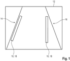
- figure 1 shows the representation of a virtual element 10 in the display area 12 of a display device 14, as is customary in the prior art.
- a three-dimensional space 16 is displayed in the display area 12 of the display device 14 .
- the display device is a head-up display.
- three-dimensional coordinates in the three-dimensional space 16 shown are determined for locating at least one virtual element 10 .
- the virtual element 10 is then transformed as a two-dimensional image 18 into the three-dimensional space 16 that is displayed in the display area 12 of the display device 14 .
- the virtual element 10 is then displayed in the display area 12 of the display device 14 with the correct perspective in relation to the three-dimensional space 16 in the driver's field of vision.
- two virtual elements 10 are displayed in the form of lines delimiting the lane.
- a major problem in the display of elements that are displayed correctly in terms of perspective is that virtual elements 10 that are located in a three-dimensional space 16 must be displayed on a 2-dimensional display area 12 . This means that the virtual elements 10 cannot be perceived by the viewer as part of the environment. So is in figure 1 an extension of the environment is intended to include lines on the road running ahead to visualize the lane. However, due to the design of the virtual image plane, these lines can sometimes not be perceived as lying on the road, but as standing and running upwards due to the ramp effect.
- figure 2 shows a representation of an embodiment of a method according to the invention, in which the disadvantages of the prior art are avoided.
- an improvement in depth perception could be improved by stereoscopic imagers.
- a stereoscopic image generator Using a stereoscopic image generator, two separate images could be generated for the two eyes. As a result, a 3D image is perceived.
- the accommodation vergence conflict occurs, which can lead to headaches, for example. This effect is often observed in 3D cinemas, for example.
- the virtual elements 10 are divided into virtual sub-elements 20, 22, 24.
- a first virtual partial element 20 is arranged in front of a second virtual partial element 22 in perspective, with a third virtual partial element 24 being arranged behind the second virtual partial element 22 in perspective.
- Further virtual sub-elements are also provided in the representation.
- the virtual partial elements 20, 22, 24 can be provided with texture gradients, for example, which make it possible to improve the depth perception of the virtual elements.
- the first virtual sub-element 20 is at a first distance 26 from the second virtual sub-element 22 on.
- the second virtual partial element 22 has a second distance 28 from the third virtual partial element 24 .
- the first distance 26 is greater than the second distance 28.
- the perspectively correct representation can also result in the distances 26, 28 between the virtual partial elements 20, 22, 24 becoming so small that they are no longer perceptible and the virtual partial elements 20, 22, 24 overlap in subjective perception. Therefore, in this exemplary embodiment of the method, it is provided that in such a case, 100 percent geometric correctness is dispensed with in favor of a higher visual quality. In this case, it means not keeping the distances 26, 28 between the partial objects constant over the entire length of the lines, but increasing them with increasing distance in the three-dimensional space 16 just enough that the distances 26, 28 remain perceptible and also one Reduction of the distances 26, 28 remains perceptible over the entire length.
- this exemplary embodiment provides that the virtual sub-elements 20. 24, 28 and/or the virtual element 10 as a whole has a depth extension, so that the virtual element 10 can be displayed smaller and higher in the display area 12 of the display device 14 as the distance increases .
Landscapes
- Engineering & Computer Science (AREA)
- Physics & Mathematics (AREA)
- Chemical & Material Sciences (AREA)
- Combustion & Propulsion (AREA)
- Transportation (AREA)
- Mechanical Engineering (AREA)
- General Physics & Mathematics (AREA)
- Optics & Photonics (AREA)
- Remote Sensing (AREA)
- Radar, Positioning & Navigation (AREA)
- Automation & Control Theory (AREA)
- Theoretical Computer Science (AREA)
- Computer Graphics (AREA)
- Geometry (AREA)
- Computing Systems (AREA)
- Instrument Panels (AREA)
- Processing Or Creating Images (AREA)
Abstract
Description
- Die Erfindung betrifft ein Verfahren zur Darstellung mindestens eines virtuellen Elements in einem Anzeigebereich mindestens einer Anzeigeeinrichtung eines Fahrzeugs, wobei im Anzeigebereich der Anzeigeeinrichtung ein dreidimensionaler Raum dargestellt wird, wobei auf Basis mindestens einer Datenquelle dreidimensionale Koordinaten im dargestellten dreidimensionalen Raum für die Verortung mindestens eines virtuellen Elements bestimmt werden, wobei das mindestens eine virtuelle Element als zweidimensionale Abbildung in den dreidimensionalen Raum, der im Anzeigebereich der Anzeigeeinrichtung dargestellt wird, transformiert wird und wobei das mindestens eine virtuelle Element im Anzeigebereich der Anzeigeeinrichtung in Bezug auf den dreidimensionalen Raum perspektivisch korrekt im Blickfeld des Fahrers dargestellt wird.
- Daneben betrifft die Erfindung eine Vorrichtung zur Darstellung mindestens eines virtuellen Elements, mit mindestens einer Anzeigeeinrichtung mit mindestens einem Anzeigebereich.
- Außerdem betrifft die Erfindung ein Fahrzeug mit einer Vorrichtung zur Darstellung mindestens eines virtuellen Elements.
- Mit der stetigen Weiterentwicklung von Virtual- und Augmented-Reality-Technologien und -Anwendungen finden diese auch Einzug in das Automobil. Bei Augmented-Reality (AR) handelt es sich um die Anreicherung der realen Welt durch virtuelle Elemente, die im dreidimensionalen Raum ortskorrekt registriert beziehungsweise verortet sind und eine Echtzeitinteraktion erlauben. Eine mögliche technische Realisierung um den Fahrerarbeitsplatz entsprechend mit perspektivisch korrekten virtuellen Augmentierungen anzureichern, bietet das Head-Up-Display (HUD).
- Gerade bei Head-Up-Displays entsteht die virtuelle Anzeige durch eine im Armaturenbrett integrierte bildgebende Einheit, wie beispielsweise ein TFT-Display. Dieses Bild wird über mehrere Spiegel in Richtung der Windschutzscheibe gelenkt, wo das Licht in das Auge des Fahrers reflektiert wird. Der Fahrer nimmt dieses Bild als eine virtuelle Anzeige im Sichtfeld wahr. Bei der Auslegung solcher Systeme wird der Bereich, in den das Licht reflektiert wird, räumlich begrenzt, um eine höhere Helligkeit durch geringere Lichtstreuung zu erzielen. Dieser Bereich wird als "EyeBox" bezeichnet, da sich das Blickfeld des Fahrers in diesem Bereich befinden muss, um eine Wahrnehmung des virtuellen Bildes zu ermöglichen.
- Ein wesentliches Problem liegt bei Head-Up-Displays darin, dass virtuelle 3D-Elemente, die in einem dreidimensionalen Raum verortet sind, auf einer 2-dimensionalen Anzeige dargestellt werden müssen. Dies führt dazu, dass die virtuellen Elemente vom Betrachter teilweise nicht als Bestandteile der Umgebung wahrgenommen werden können. Eine als Erweiterung der Umgebung auf der Straße liegende, nach vorne laufende Linie könnte, aufgrund der Auslegung der virtuellen Bildebene, teilweise nicht als auf der Fahrbahn liegend, sondern als stehend und nach oben laufend wahrgenommen werden. Dieser Wahrnehmungsfehler wird im Folgenden als Rampeneffekt bezeichnet. Um den Rampeneffekt zu reduzieren, muss die menschliche Tiefenwahrnehmung berücksichtig werden.
- Die
DE 11 2017 006 054 T5 zeigt beispielsweise ein System zur Darstellung von virtuellen Elementen auf einem Head-Up-Display. Wobei eine Vorrichtung, die dazu dient, virtuelle Elemente auf dem Anzeigebereich des Head-Up-Displays darzustellen, eine optische Achse aufweist, die unterschiedliche Bildrealisierungsflächen umfasst, sodass Bilder, die auf dem Anzeigebereich dargestellt werden, eine unterschiedliche virtuelle Distanz aufweisen, sodass der Betrachter unterschiedliche Tiefenwahrnehmungen der virtuellen Elemente erfährt. - Ein Nachteil besteht darin, dass bei einer Erhöhung der Bilddistanz ein größerer Bauraum für die Anzeigevorrichtung benötigt wird, um die Tiefenwahrnehmung zu verbessern.
- Die
US 2011/0102303 A1 zeigt ein Verfahren zur Darstellung von virtuellen Elementen in Form von Abbiegehinweisen, die ein Abbiegemanöver schrittweise in Abhängigkeit der Entfernung ankündigen. Die Abbiegehinweise sind beispielsweise in einem Abstand von 90 m, 60 m und 30 m vor der Abbiegung als virtuelle Elemente im Blickfeld des Fahrers dargestellt und nach Möglichkeit perspektivisch korrekt dargestellt. Allerdings besteht dabei die Gefahr, dass der oben genannte Rampeneffekt eintritt. - Der Erfindung liegt nun die Aufgabe zugrunde, ein Verfahren zum Anzeigen eines virtuellen Elements, eine entsprechende Vorrichtung sowie ein Fahrzeug anzugeben, bei denen die Tiefenwahrnehmung von virtuellen Elementen im Anzeigebereich einer Anzeigeeinrichtung verbessert wird.
- Diese Aufgabe ist bei der vorliegenden Erfindung zunächst durch die Merkmale des Kennzeichnungsteils des Patentanspruchs 1 dadurch gelöst, dass das virtuelle Element aus mindestens einem ersten virtuellen Teilelement und einem zweiten virtuellen Teilelement aufgebaut wird, wobei das erste virtuelle Teilelement perspektivisch im Anzeigebereich vor dem zweiten Teilelement angeordnet wird.
- Beim Anzeigebereich der Anzeigeeinrichtung kann es sich um ein Display im Mittelbereich oder im Cockpitbereich, beispielsweise im Kombiinstrument des Fahrzeugs, handeln. Alternativ oder zusätzlich kann der Anzeigebereich der Anzeigeeinrichtung als Head-Up-Display ausgestaltet sein. Unter Head-Up-Display ist ein Anzeigebereich zu verstehen, bei dem der Fahrer seine Kopfhaltung beziehungsweise Blickrichtung beibehalten kann, weil die Informationen in sein Sichtfeld, beispielsweise auf die Windschutzscheibe des Fahrzeugs, projiziert werden.
- Der dargestellte dreidimensionale Raum kann vorzugsweise einen Bereich außerhalb des Fahrzeugs in Fahrtrichtung beschreiben. Bei einem Head-Up-Display ist der Anzeigebereich der Anzeigeeinrichtung beziehungsweise der dreidimensionale Raum gleichzusetzen mit dem Blick durch die Windschutzscheibe. Der dreidimensionale Raum ist dann folglich der Raum vor dem Fahrzeug im Blickfeld des Fahrers beziehungsweise des Beifahrers. Bei den entsprechend zum virtuellen Element berechneten dreidimensionalen Koordinaten kann es sich beispielsweise um kartesische Koordinaten handeln.
- Die zur Berechnung der Koordinaten benötigten Datenquellen können unterschiedlicher Art sein. Bevorzugt handelt es sich bei diesen Datenquellen um Fahrzeugdaten beziehungsweise Navigationsdaten, die durch die Positionierungssensorik des Fahrzeugs, wie zum Beispiel GPS, Drehratensensoren oder Kameras aufgenommen werden.
- Bei dem virtuellen Element kann es sich um verschiedene Bildelemente und/oder Schaltflächen handeln, die im Anzeigebereich der Anzeigeeinrichtung dargestellt werden. Die virtuellen Elemente können eine Verbindung zu Fahrzeugdaten aufweisen und/oder abhängig von den Fahreigenschaften des Fahrzeugs sein. Die Daten können zum Beispiel aus vorhandenen Fahrassistenzsystemen stammen. Es ist aber auch denkbar, dass die dargestellten virtuellen Elemente irrelevant für die Fahreigenschaften des Fahrzeugs sind.
- Die virtuellen Teilelemente ergeben zusammen genommen das gesamte virtuelle Element. Durch die Aufteilung des virtuellen Elements ist es möglich, die Teilelemente unterschiedlich auszugestalten, um die Tiefenwahrnehmung für den Betrachter beziehungsweise den Fahrer des Fahrzeugs möglichst realistisch wirken zu lassen.
- Weitere bevorzugte Ausgestaltungen der Erfindung ergeben sich aus den übrigen, in den Unteransprüchen genannten Merkmalen.
- Dazu ist bei einer ersten Ausgestaltung des erfindungsgemäßen Verfahrens vorgesehen, dass das erste virtuelle Teilelement und das zweite virtuelle Teilelement mit einer Tiefenausdehnung dargestellt werden, sodass das virtuelle Element mit zunehmender Entfernung kleiner und höher im Anzeigebereich der Anzeigeeinrichtung dargestellt wird. Elemente, die im Hintergrund dargestellt werden, sind bei einer perspektivischen Darstellung in der Regel kleiner als Elemente im Vordergrund. Eine im Anzeigebereich dargestellte Linie, die beispielsweise die Berandung der Fahrbahn darstellen soll, kann also perspektivisch derart dargestellt werden, dass die virtuellen Teilelemente, durch die diese Linie dargestellt wird, ihre Größe schrittweise verkleinern. Der Rampeneffekt tritt dann nicht auf, da für den Fahrer der Anschein entsteht, dass die Linie sich in die Bildebene erstreckt.
- Bei einer weiteren vorteilhaften Ausgestaltung des erfindungsgemäßen Verfahrens ist vorgesehen, dass das erste virtuelle Teilelement und das zweite virtuelle Teilelement einen Texturgradienten aufweisen. Auf diese Weise können bei den virtuellen Teilelementen, die weiter im Hintergrund liegenden Teilelemente mit einer anderen Textur versehen werden, als die virtuellen Teilelemente, die weiter im Vordergrund liegen. Somit kann eine realistischere Tiefenwahrnehmung generiert werden.
- Alternativ oder zusätzlich ist bei einer weiteren Ausgestaltung des erfindungsgemäßen Verfahrens vorgesehen, dass das erste virtuelle Teilelement und das zweite virtuelle Teilelement einen Schärfegradienten aufweisen. Analog zu den obigen Ausführungen können die virtuellen Teilelemente, die weiter im Hintergrund liegen, eine höhere Unschärfe aufweisen als die virtuellen Teilelemente, die weiter im Vordergrund liegen, wodurch eine realistischere Tiefenwahrnehmung für den Fahrer des Fahrzeugs generiert werden kann. In Abhängigkeit der Distanz der dreidimensionalen Objekte kann es bei geringen Distanzen auch sinnvoll sein, dass die näher im Vordergrund liegenden Objekte eine geringere Schärfe aufweisen als die weiter im Hintergrund liegenden dreidimensionalen Objekte. Eine Kombination beider Ausgestaltungen ist ebenfalls möglich. Hierzu sind mindestens drei virtuelle Teilelemente notwendig, wobei das vordere virtuelle Teilelement und das hintere virtuelle Teilelement jeweils eine höhere Unschärfe aufweisen als das mittlere virtuelle Teilelement.
- Ebenfalls alternativ oder zusätzlich ist bei einer weiteren Ausgestaltung der Erfindung vorgesehen, dass das erste virtuelle Element und das zweite virtuelle Element einen Helligkeitsgradienten aufweisen. Entsprechend weiter im Hintergrund liegende virtuelle Teilelemente können eine geringere Helligkeit aufweisen, als virtuelle Teilelemente, die weiter im Vordergrund liegen, um die Tiefenwahrnehmung für den Fahrer des Fahrzeugs realistischer zu gestalten.
- Bei einer weiteren Ausgestaltung des erfindungsgemäßen Verfahrens ist mindestens ein drittes virtuelles Teilelement vorgesehen. Das dritte virtuelle Teilelement wird perspektivisch im Anzeigebereich hinter dem zweiten Teilelement angeordnet. Das erste virtuelle Teilelement weist einen ersten Abstand zum zweiten virtuellen Teilelement auf, wobei das zweite virtuelle Teilelement einen zweiten Abstand zum dritten virtuellen Teilelement aufweist. Der erste Abstand ist größer als der zweite Abstand. Je weiter die virtuellen Teilelemente perspektivisch im Hintergrund liegen, desto näher werden sie aneinander gerückt, um die Tiefenwahrnehmung für den Fahrer des Fahrzeugs zu verbessern.
- Bei einer bevorzugten Ausgestaltung der Erfindung wird die Qualität der geometrisch korrekten Darstellung des virtuellen Elements in Abhängigkeit der visuellen Qualität des virtuellen Elements für einen Fahrer des Fahrzeugs überprüft.
- Eine besonders bevorzugte Ausgestaltung des erfindungsgemäßen Verfahrens sieht darüber hinaus vor, dass die Qualität der geometrisch korrekten Darstellung des virtuellen Elements reduziert wird, wenn die visuelle Qualität des virtuellen Elements einen zuvor bestimmten Grenzwert erreicht. In Abhängigkeit der Perspektive des Betrachters kann die perspektivisch korrekte Darstellung dazu führen, dass Abstände zwischen virtuellen Teilelementen so klein werden, dass sie nicht mehr wahrnehmbar sind und die Teilobjekte sich in der subjektiven Wahrnehmung überlagern.
- Daher sieht die Erfindung vor, dass in so einem Fall von einer 100 prozentigen geometrischen Korrektheit zu Gunsten einer höheren visuellen Qualität abgesehen wird. In diesem Fall bedeutet es, die Abstände zwischen den Teilobjekten nicht über die gesamte Länge der Linien konstant zu halten, sondern mit zunehmender Entfernung im dreidimensionalen Raum gerade so weit zu erhöhen, dass die Abstände wahrnehmbar bleiben und auch eine Reduktion der Abstände über die gesamte Länge wahrnehmbar bleibt.
- Die zuvor genannte Aufgabe wird außerdem gelöst von einer Vorrichtung, gemäß dem Kennzeichnungsteil des Patentanspruchs 9, dass die Anzeigeeinrichtung dafür ausgelegt ist, ein erfindungsgemäßes Verfahren durchzuführen. Die obigen Ausführungen zum erfindungsgemäßen Verfahren gelten entsprechend auch für die erfindungsgemäße Vorrichtung.
- Bei der Vorrichtung kann es sich beispielsweise um ein Navigationssystem handeln, das eine grafische Ausgabe von kontaktanalogen Elementen gemäß der erfindungsgemäßen Vorrichtung ermöglicht.
- Daneben wird die zuvor genannte Aufgabe gelöst von einem Fahrzeug, gemäß dem Kennzeichnungsteil des Patentanspruchs 10, mit einer Vorrichtung zur Darstellung mindestens eines virtuellen Elements, wobei die Vorrichtung erfindungsgemäß ausgestaltet ist. Die obigen Ausführungen zur erfindungsgemäßen Vorrichtung gelten entsprechend auch für das erfindungsgemäße Fahrzeug.
- Die verschiedenen in dieser Anmeldung genannten Ausführungsformen der Erfindung sind, sofern im Einzelfall nicht anders ausgeführt, mit Vorteil miteinander kombinierbar.
- Die Erfindung wird nachfolgend in Ausführungsbeispielen anhand der zugehörigen Zeichnungen erläutert. Es zeigen:
- Figur 1
- schematisch eine aus dem Stand der Technik bekannte Darstellung eines kontaktanalogen virtuellen Elements und
- Figur 2
- schematisch die Darstellung eines kontaktanalogen virtuellen Elements gemäß einem Ausführungsbeispiel eines erfindungsgemäßen Verfahrens.
-
Figur 1 zeigt die Darstellung eines virtuellen Elements 10 im Anzeigebereich 12 einer Anzeigeeinrichtung 14, wie sie im Stand der Technik üblich ist. Dabei wird im Anzeigebereich 12 der Anzeigeeinrichtung 14 ein dreidimensionaler Raum 16 dargestellt. Bei der Anzeigeeinrichtung handelt es sich in dieser Ausführung um ein Head-Up-Display. Auf Basis mindestens einer Datenquelle werden dreidimensionale Koordinaten im dargestellten dreidimensionalen Raum 16 für die Verortung mindestens eines virtuellen Elements 10 bestimmt. - Das virtuelle Element 10 wird dann als zweidimensionale Abbildung 18 in den dreidimensionalen Raum 16 der im Anzeigebereich 12 der Anzeigeeinrichtung 14 dargestellt wird, transformiert. Anschließend wird das virtuelle Element 10 im Anzeigebereich 12 der Anzeigeeinrichtung 14 in Bezug auf den dreidimensionalen Raum 16 perspektivisch korrekt im Blickfeld des Fahrers dargestellt. Im vorliegenden Beispiel werden zwei virtuelle Elemente 10 in Form von Linien als Begrenzung der Fahrspur angezeigt.
- Ein wesentliches Problem liegt bei der Darstellung von perspektivisch korrekt dargestellten Elementen darin, dass virtuelle Elemente 10, die in einem dreidimensionalen Raum 16 verortet sind, auf einem 2-dimensionalen Anzeigebereich 12 dargestellt werden müssen. Dies führt dazu, dass die virtuellen Elemente 10 vom Betrachter teilweise nicht als Bestandteile der Umgebung wahrgenommen werden können. So ist in
Figur 1 eine Erweiterung der Umgebung um auf der Straße liegende, nach vorne laufende Linien zur Visualisierung der Fahrspur beabsichtigt. Jedoch können diese Linien, aufgrund der Auslegung der virtuellen Bildebene, teilweise nicht als auf der Fahrbahn liegend, sondern, aufgrund des Rampeneffekts, als stehend und nach oben laufend wahrgenommen werden. -
Figur 2 zeigt eine Darstellung eines Ausführungsbeispiels eines erfindungsgemäßen Verfahrens, bei denen die Nachteile aus dem Stand der Technik vermieden werden. Grundsätzlich könnte eine Verbesserung der Tiefenwahrnehmung durch stereoskopische Bildgeber verbessert werden. Mithilfe eines stereoskopischen Bildgebers könnten zwei separate Bilder für die beiden Augen generiert werden. Dadurch wird ein 3D-Bild wahrgenommen. Allerdings tritt bei stereoskopischen Displays der Akkommodations-Vergenz Konflikt auf, der zum Beispiel zu Kopfschmerzen führen kann. Dieser Effekt wird beispielsweise häufig in 3D-Kinos beobachtet. - In
Figur 2 sind die virtuellen Elemente 10 in virtuelle Teilelemente 20, 22, 24 aufgeteilt. Dabei ist ein erstes virtuelles Teilelement 20 perspektivisch vor einem zweiten virtuellen Teilelement 22 angeordnet, wobei ein drittes virtuelles Teilelement 24 perspektivisch hinter dem zweiten virtuellen Teilelement 22 angeordnet ist. In der Darstellung sind noch weitere virtuelle Teilelemente vorgesehen. - Durch Aufteilung der virtuellen Elemente 10 in virtuelle Teilelemente 20, 22, 24 können die virtuellen Teilelemente 20, 22, 24 beispielsweise mit Texturgradienten versehen sein, die es ermöglichen, die Tiefenwahrnehmung der virtuellen Elemente zu verbessern. Dabei weist das erste virtuelle Teilelement 20 einen ersten Abstand 26 zum zweiten virtuellen Teilelement 22 auf. Das zweite virtuelle Teilelement 22 weist einen zweiten Abstand 28 zum dritten virtuellen Teilelement 24 auf. Der erste Abstand 26 ist größer als der zweite Abstand 28. Somit ist der Abstand zwischen zwei virtuellen Teilelementen umso kleiner, je weiter diese virtuellen Teilelemente perspektivisch im Hintergrund angeordnet sind, wodurch die Tiefenwahrnehmung verbessert wird.
- In Abhängigkeit der Perspektive des Betrachters kann die perspektivisch korrekte Darstellung jedoch auch dazu führen, dass die Abstände 26, 28 zwischen den virtuellen Teilelementen 20, 22, 24 so klein werden, dass sie nicht mehr wahrnehmbar sind und die virtuellen Teilelemente 20, 22, 24 sich in der subjektiven Wahrnehmung überlagern. Daher ist bei diesem Ausführungsbeispiel des Verfahrens vorgesehen, dass in so einem Fall von einer 100 prozentigen geometrischen Korrektheit zu Gunsten einer höheren visuellen Qualität abgesehen wird. In diesem Fall bedeutet es, die Abstände 26, 28 zwischen den Teilobjekten nicht über die gesamte Länge der Linien konstant zu halten, sondern mit zunehmender Entfernung im dreidimensionalen Raum 16 gerade so weit zu erhöhen, dass die Abstände 26, 28 wahrnehmbar bleiben und auch eine Reduktion der Abstände 26, 28 über die gesamte Länge wahrnehmbar bleibt.
- Zusätzlich ist bei diesem Ausführungsbeispiel vorgesehen, dass die virtuellen Teilelemente 20. 24, 28, und/oder das virtuelle Element 10 als Ganzes eine Tiefenausdehnung aufweist, sodass das virtuelle Element 10 mit zunehmender Entfernung kleiner und höher im Anzeigebereich 12 der Anzeigeeinrichtung 14 dargestellt werden kann. Daneben ist vorgesehen, dass die virtuellen Teilelemente 20. 24, 28, und/oder das virtuelle Element 10 als Ganzes, mit einem Schärfegradienten versehen sind, der es ermöglicht, dass virtuelle Elemente 10 umso diffuser dargestellt werden, je weiter diese perspektivisch entfernt sind. Außerdem ist vorgesehen, dass die virtuellen Teilelemente 20. 24, 28, und/oder das virtuelle Element 10 als Ganzes, einen Helligkeitsgradienten aufweist, der es ermöglicht, dass virtuelle Elemente 10 umso dunkler dargestellt werden, je weiter diese perspektivisch entfernt sind.
-
- 10
- Virtuelles Element
- 12
- Anzeigebereich
- 14
- Anzeigeeinrichtung
- 16
- Dreidimensionaler Raum
- 18
- Zweidimensionale Abbildung
- 20
- Erstes virtuelles Teilelement
- 22
- Zweites virtuelles Teilelement
- 24
- Drittes virtuelles Teilelement
- 26
- Erster Abstand
- 28
- Zweiter Abstand
Claims (10)
- Verfahren zur Darstellung mindestens eines virtuellen Elements (10) in einem Anzeigebereich (12) mindestens einer Anzeigeeinrichtung (14) eines Fahrzeugs, wobei im Anzeigebereich (12) der Anzeigeeinrichtung (14) ein dreidimensionaler Raum (16) dargestellt wird, wobei auf Basis mindestens einer Datenquelle dreidimensionale Koordinaten im dargestellten dreidimensionalen Raum (16) für die Verortung mindestens eines virtuellen Elements (10) bestimmt werden, wobei das mindestens eine virtuelle Element (10) als zweidimensionale Abbildung (18) in den dreidimensionalen Raum (16), der im Anzeigebereich (12) der Anzeigeeinrichtung (14) dargestellt wird, transformiert wird und wobei das mindestens eine virtuelle Element (10) im Anzeigebereich (12) der Anzeigeeinrichtung (14) in Bezug auf den dreidimensionalen Raum (16) perspektivisch korrekt im Blickfeld des Fahrers dargestellt wird, dadurch gekennzeichnet, dass das virtuelle Element (10) aus mindestens einem ersten virtuellen Teilelement (20) und einem zweiten virtuellen Teilelement (22) aufgebaut wird, wobei das erste virtuelle Teilelement (20) perspektivisch im Anzeigebereich vor dem zweiten Teilelement (22) angeordnet wird.
- Verfahren nach Anspruch 1, dadurch gekennzeichnet, dass das erste virtuelle Teilelement (20) und das zweite virtuelle Teilelement (22) mit einer Tiefenausdehnung dargestellt werden sodass das virtuelle Element (10) mit zunehmender Entfernung kleiner und höher im Anzeigebereich (12) der Anzeigeeinrichtung (14) dargestellt wird.
- Verfahren nach Anspruch 1 oder 2, dadurch gekennzeichnet, dass das erste virtuelle Teilelement (20) und das zweite virtuelle Teilelement (22) einen Texturgradienten aufweisen.
- Verfahren nach einem der Ansprüche 1 bis 3, dadurch gekennzeichnet, dass das erste virtuelle Teilelement (20) und das zweite virtuelle Teilelement (22) einen Schärfegradienten aufweisen.
- Verfahren nach einem der Ansprüche 1 bis 4, dadurch gekennzeichnet, dass das erste virtuelle Teilelement (20) und das zweite virtuelle Teilelement (22) einen Helligkeitsgradienten aufweisen.
- Verfahren nach einem der Ansprüche 1 bis 5, dadurch gekennzeichnet, dass mindestens ein drittes virtuelles Teilelement (24) vorgesehen ist, dass das dritte virtuelle Teilelement (24) perspektivisch im Anzeigebereich (12) hinter dem zweiten virtuellen Teilelement (22) angeordnet wird, dass das erste virtuelle Teilelement (20) einen ersten Abstand zum zweiten virtuellen Teilelement (22) aufweist, dass das zweite virtuelle Teilelement (22) einen zweiten Abstand zum dritten virtuellen Teilelement (24) aufweist und dass der erste Abstand (26) größer ist als der zweite Abstand (28).
- Verfahren nach einem der Ansprüche 1 bis 6, dadurch gekennzeichnet, dass die Qualität der geometrisch korrekten Darstellung des virtuellen Elements (10) in Abhängigkeit der visuellen Qualität des virtuellen Elements (10) für einen Fahrer des Fahrzeugs überprüft wird.
- Verfahren nach Anspruch 7, dadurch gekennzeichnet, dass die Qualität der geometrisch korrekten Darstellung des virtuellen Elements (10) reduziert wird, wenn die visuelle Qualität des virtuellen Elements (10) einen zuvor bestimmten Grenzwert erreicht.
- Vorrichtung zur Darstellung mindestens eines virtuellen Elements (10), mit mindestens einer Anzeigeeinrichtung (14) mit mindestens einem Anzeigebereich (12), dadurch gekennzeichnet, dass die Anzeigeeinrichtung (14) dafür ausgelegt ist, ein Verfahren nach einem der Ansprüche 1 bis 8 durchzuführen.
- Fahrzeug mit einer Vorrichtung zur Darstellung mindestens eines virtuellen Elements (10), dadurch gekennzeichnet, dass die Vorrichtung gemäß Anspruch 9 ausgestaltet ist.
Applications Claiming Priority (1)
| Application Number | Priority Date | Filing Date | Title |
|---|---|---|---|
| DE102020211298.3A DE102020211298A1 (de) | 2020-09-09 | 2020-09-09 | Verfahren zur Darstellung eines virtuellen Elements |
Publications (2)
| Publication Number | Publication Date |
|---|---|
| EP3967537A1 true EP3967537A1 (de) | 2022-03-16 |
| EP3967537B1 EP3967537B1 (de) | 2024-05-22 |
Family
ID=77398492
Family Applications (1)
| Application Number | Title | Priority Date | Filing Date |
|---|---|---|---|
| EP21191949.3A Active EP3967537B1 (de) | 2020-09-09 | 2021-08-18 | Verfahren zur darstellung eines virtuellen elements |
Country Status (4)
| Country | Link |
|---|---|
| US (1) | US12179591B2 (de) |
| EP (1) | EP3967537B1 (de) |
| CN (1) | CN114236822B (de) |
| DE (1) | DE102020211298A1 (de) |
Families Citing this family (1)
| Publication number | Priority date | Publication date | Assignee | Title |
|---|---|---|---|---|
| KR102705360B1 (ko) * | 2020-07-08 | 2024-09-09 | 현대모비스 주식회사 | 서라운드뷰 모니터링 시스템 및 방법 |
Citations (9)
| Publication number | Priority date | Publication date | Assignee | Title |
|---|---|---|---|---|
| US20110102303A1 (en) | 2009-11-04 | 2011-05-05 | Denso Corporation | Display apparatus for vehicle |
| US20190049724A1 (en) * | 2017-08-08 | 2019-02-14 | Alpine Electronics, Inc. | Head-up display device, navigation device, and display method |
| JP2019138773A (ja) * | 2018-02-09 | 2019-08-22 | トヨタ自動車株式会社 | 表示装置 |
| DE102018203462A1 (de) * | 2018-03-07 | 2019-09-12 | Volkswagen Aktiengesellschaft | Verfahren zur Berechnung einer Einblendung von Zusatzinformationen für eine Anzeige auf einer Anzeigeeinheit, Vorrichtung zur Durchführung des Verfahrens sowie Kraftfahrzeug und Computerprogramm |
| DE112017006054T5 (de) | 2016-11-30 | 2019-09-19 | Cambridge Enterprise Limited | Mehrtiefe augmented realitätsanzeige |
| WO2019188581A1 (ja) * | 2018-03-30 | 2019-10-03 | 日本精機株式会社 | 表示制御装置、ヘッドアップディスプレイ装置 |
| WO2019189515A1 (en) * | 2018-03-28 | 2019-10-03 | Ricoh Company, Ltd. | Control apparatus, display apparatus, movable body, and image display method |
| WO2020009219A1 (ja) * | 2018-07-05 | 2020-01-09 | 日本精機株式会社 | ヘッドアップディスプレイ装置 |
| US20200143569A1 (en) * | 2017-08-10 | 2020-05-07 | Nippon Seiki Co., Ltd. | Vehicle display device |
Family Cites Families (12)
| Publication number | Priority date | Publication date | Assignee | Title |
|---|---|---|---|---|
| JP2007121001A (ja) | 2005-10-26 | 2007-05-17 | Matsushita Electric Ind Co Ltd | ナビゲーション装置 |
| JP4886751B2 (ja) * | 2008-09-25 | 2012-02-29 | 株式会社東芝 | 車載用表示システム及び表示方法 |
| JP2010121704A (ja) | 2008-11-19 | 2010-06-03 | Ntn Corp | ブーツ取付構造 |
| EP2462480A2 (de) * | 2009-08-07 | 2012-06-13 | Light Blue Optics Ltd. | Headup-anzeigen |
| DE102013212667A1 (de) | 2013-06-28 | 2014-12-31 | Robert Bosch Gmbh | Verfahren und Vorrichtung zum Darstellen eines dreidimensionalen Bildes unter Verwendung eines Bildgebers einer Blickfeldanzeigeeinrichtung für ein Fahrzeug |
| JP6516223B2 (ja) | 2015-06-30 | 2019-05-22 | パナソニックIpマネジメント株式会社 | 表示装置 |
| DE102015225343B4 (de) | 2015-12-15 | 2022-07-07 | Volkswagen Aktiengesellschaft | Fortbewegungsmittel und Anordnung für ein Fortbewegungsmittel zur Ausgabe richtungsanaloger Hinweise auf Umgebungsdetails |
| JP6512449B2 (ja) | 2016-01-20 | 2019-05-15 | パナソニックIpマネジメント株式会社 | 表示装置 |
| JP6938367B2 (ja) * | 2017-12-28 | 2021-09-22 | アルパイン株式会社 | 車載システム |
| JP7052786B2 (ja) * | 2018-12-14 | 2022-04-12 | 株式会社デンソー | 表示制御装置および表示制御プログラム |
| JP2020121704A (ja) | 2019-01-31 | 2020-08-13 | 日本精機株式会社 | 表示制御装置、ヘッドアップディスプレイ装置、方法、及びコンピュータ・プログラム |
| JP7476568B2 (ja) * | 2019-09-02 | 2024-05-01 | 株式会社アイシン | 重畳画像表示装置、重畳画像描画方法及びコンピュータプログラム |
-
2020
- 2020-09-09 DE DE102020211298.3A patent/DE102020211298A1/de active Pending
-
2021
- 2021-08-18 EP EP21191949.3A patent/EP3967537B1/de active Active
- 2021-09-08 US US17/469,177 patent/US12179591B2/en active Active
- 2021-09-09 CN CN202111055355.7A patent/CN114236822B/zh active Active
Patent Citations (9)
| Publication number | Priority date | Publication date | Assignee | Title |
|---|---|---|---|---|
| US20110102303A1 (en) | 2009-11-04 | 2011-05-05 | Denso Corporation | Display apparatus for vehicle |
| DE112017006054T5 (de) | 2016-11-30 | 2019-09-19 | Cambridge Enterprise Limited | Mehrtiefe augmented realitätsanzeige |
| US20190049724A1 (en) * | 2017-08-08 | 2019-02-14 | Alpine Electronics, Inc. | Head-up display device, navigation device, and display method |
| US20200143569A1 (en) * | 2017-08-10 | 2020-05-07 | Nippon Seiki Co., Ltd. | Vehicle display device |
| JP2019138773A (ja) * | 2018-02-09 | 2019-08-22 | トヨタ自動車株式会社 | 表示装置 |
| DE102018203462A1 (de) * | 2018-03-07 | 2019-09-12 | Volkswagen Aktiengesellschaft | Verfahren zur Berechnung einer Einblendung von Zusatzinformationen für eine Anzeige auf einer Anzeigeeinheit, Vorrichtung zur Durchführung des Verfahrens sowie Kraftfahrzeug und Computerprogramm |
| WO2019189515A1 (en) * | 2018-03-28 | 2019-10-03 | Ricoh Company, Ltd. | Control apparatus, display apparatus, movable body, and image display method |
| WO2019188581A1 (ja) * | 2018-03-30 | 2019-10-03 | 日本精機株式会社 | 表示制御装置、ヘッドアップディスプレイ装置 |
| WO2020009219A1 (ja) * | 2018-07-05 | 2020-01-09 | 日本精機株式会社 | ヘッドアップディスプレイ装置 |
Also Published As
| Publication number | Publication date |
|---|---|
| US12179591B2 (en) | 2024-12-31 |
| CN114236822B (zh) | 2025-01-28 |
| US20220072957A1 (en) | 2022-03-10 |
| CN114236822A (zh) | 2022-03-25 |
| EP3967537B1 (de) | 2024-05-22 |
| DE102020211298A1 (de) | 2022-03-10 |
Similar Documents
| Publication | Publication Date | Title |
|---|---|---|
| DE102017216774B4 (de) | Verfahren, Vorrichtung, computerlesbares Speichermedium und Kraftfahrzeug mit Instruktionen zur Steuerung einer Anzeige einer Augmented-Reality-Head-up-Display-Vorrichtung für ein Kraftfahrzeug | |
| DE102014019122B4 (de) | Verfahren zum Betreiben eines Anzeigesystems, Anzeigesystem und Kraftwagen mit einem Anzeigesystem | |
| EP3685123B1 (de) | Verfahren, vorrichtung und computerlesbares speichermedium mit instruktionen zur steuerung einer anzeige einer augmented-reality-head-up-display-vorrichtung für ein kraftfahrzeug | |
| DE102014000803B4 (de) | Fahrzeug, Anzeigesystem und Verfahren zum Anzeigen einer verkehrsrelevanten Information | |
| DE112019000329B4 (de) | Anzeigesystem, bewegliches objekt und gestaltungsverfahren | |
| DE102020107644A1 (de) | Anzeigeverbundsystem zum Einsatz in einem Fahrzeug | |
| EP4005894A1 (de) | Verfahren zur darstellung eines virtuellen elements | |
| EP3361355A1 (de) | Verfahren, vorrichtung und computerlesbares speichermedium mit instruktionen zur steuerung einer anzeige einer augmented-reality-head-up-display-vorrichtung | |
| DE102017209802A1 (de) | Verfahren und Vorrichtung zum Betreiben eines Anzeigesystems mit einer Datenbrille | |
| EP3296795A1 (de) | Verfahren zur darstellung eines bildobjekts in einem fahrzeug auf einer fahrzeugintern und einer fahrzeugextern wahrgenommenen anzeige | |
| EP3978877B1 (de) | Horizontale positionsfestlegung für das einblenden virtueller objekte bei einer head-up- displayeinrichtung | |
| DE102022123223A1 (de) | Übertragung visueller Anzeigeinhalte zwischen einer fahrzeuggebundenen und einer brillengebundenen Darstellung in einem Fahrzeug | |
| EP2888623B1 (de) | Betreiben eines head-up-displays eines fahrzeugs und bildermittlungssystem für das head-up-display | |
| EP3983252B1 (de) | Generieren einer anzeige eines augmented-reality-head-up-displays für ein kraftfahrzeug | |
| DE102017208339A1 (de) | Projektionsanzeigevorrichtung zur Darstellung eines virtuellen Anzeigebildes in verschiedenen Anzeigeebenen und Verfahren zum Betreiben einer Projektionsanzeigevorrichtung | |
| WO2016165799A1 (de) | Verfahren zum betreiben einer virtual-reality-brille und system mit einer virtual-reality-brille | |
| EP3967537B1 (de) | Verfahren zur darstellung eines virtuellen elements | |
| DE102013016249A1 (de) | Verfahren und Vorrichtung zur Darstellung von Navigationshinweisen | |
| DE102016214438B4 (de) | Kraftfahrzeug mit einem Head-up-Display und Verfahren zum Betrieb desselben | |
| EP3967538B1 (de) | Verfahren zur darstellung eines virtuellen elements | |
| DE102015205868A1 (de) | Verfahren und Vorrichtung zum Betreiben einer Anzeigevorrichtung in einem Kraftfahrzeug | |
| DE102013210587A1 (de) | Anzeigensystem mit Datenbrille | |
| WO2022048905A1 (de) | Verfahren zum vorbereiten eines navigationsmanövers eines fahrzeugs | |
| DE19836002B4 (de) | Stereoskopische Flugführungshilfe | |
| DE102016225267B4 (de) | Datenbrille und Verfahren zum Betreiben einer Datenbrille |
Legal Events
| Date | Code | Title | Description |
|---|---|---|---|
| PUAI | Public reference made under article 153(3) epc to a published international application that has entered the european phase |
Free format text: ORIGINAL CODE: 0009012 |
|
| STAA | Information on the status of an ep patent application or granted ep patent |
Free format text: STATUS: THE APPLICATION HAS BEEN PUBLISHED |
|
| AK | Designated contracting states |
Kind code of ref document: A1 Designated state(s): AL AT BE BG CH CY CZ DE DK EE ES FI FR GB GR HR HU IE IS IT LI LT LU LV MC MK MT NL NO PL PT RO RS SE SI SK SM TR |
|
| STAA | Information on the status of an ep patent application or granted ep patent |
Free format text: STATUS: REQUEST FOR EXAMINATION WAS MADE |
|
| 17P | Request for examination filed |
Effective date: 20220916 |
|
| RBV | Designated contracting states (corrected) |
Designated state(s): AL AT BE BG CH CY CZ DE DK EE ES FI FR GB GR HR HU IE IS IT LI LT LU LV MC MK MT NL NO PL PT RO RS SE SI SK SM TR |
|
| GRAP | Despatch of communication of intention to grant a patent |
Free format text: ORIGINAL CODE: EPIDOSNIGR1 |
|
| STAA | Information on the status of an ep patent application or granted ep patent |
Free format text: STATUS: GRANT OF PATENT IS INTENDED |
|
| INTG | Intention to grant announced |
Effective date: 20240125 |
|
| RAP3 | Party data changed (applicant data changed or rights of an application transferred) |
Owner name: VOLKSWAGEN AKTIENGESELLSCHAFT |
|
| P01 | Opt-out of the competence of the unified patent court (upc) registered |
Effective date: 20240227 |
|
| GRAS | Grant fee paid |
Free format text: ORIGINAL CODE: EPIDOSNIGR3 |
|
| GRAA | (expected) grant |
Free format text: ORIGINAL CODE: 0009210 |
|
| STAA | Information on the status of an ep patent application or granted ep patent |
Free format text: STATUS: THE PATENT HAS BEEN GRANTED |
|
| AK | Designated contracting states |
Kind code of ref document: B1 Designated state(s): AL AT BE BG CH CY CZ DE DK EE ES FI FR GB GR HR HU IE IS IT LI LT LU LV MC MK MT NL NO PL PT RO RS SE SI SK SM TR |
|
| REG | Reference to a national code |
Ref country code: GB Ref legal event code: FG4D Free format text: NOT ENGLISH |
|
| REG | Reference to a national code |
Ref country code: CH Ref legal event code: EP |
|
| REG | Reference to a national code |
Ref country code: DE Ref legal event code: R096 Ref document number: 502021003773 Country of ref document: DE |
|
| REG | Reference to a national code |
Ref country code: IE Ref legal event code: FG4D Free format text: LANGUAGE OF EP DOCUMENT: GERMAN |
|
| REG | Reference to a national code |
Ref country code: LT Ref legal event code: MG9D |
|
| REG | Reference to a national code |
Ref country code: NL Ref legal event code: MP Effective date: 20240522 |
|
| PG25 | Lapsed in a contracting state [announced via postgrant information from national office to epo] |
Ref country code: IS Free format text: LAPSE BECAUSE OF FAILURE TO SUBMIT A TRANSLATION OF THE DESCRIPTION OR TO PAY THE FEE WITHIN THE PRESCRIBED TIME-LIMIT Effective date: 20240922 |
|
| PG25 | Lapsed in a contracting state [announced via postgrant information from national office to epo] |
Ref country code: BG Free format text: LAPSE BECAUSE OF FAILURE TO SUBMIT A TRANSLATION OF THE DESCRIPTION OR TO PAY THE FEE WITHIN THE PRESCRIBED TIME-LIMIT Effective date: 20240522 |
|
| PG25 | Lapsed in a contracting state [announced via postgrant information from national office to epo] |
Ref country code: HR Free format text: LAPSE BECAUSE OF FAILURE TO SUBMIT A TRANSLATION OF THE DESCRIPTION OR TO PAY THE FEE WITHIN THE PRESCRIBED TIME-LIMIT Effective date: 20240522 Ref country code: FI Free format text: LAPSE BECAUSE OF FAILURE TO SUBMIT A TRANSLATION OF THE DESCRIPTION OR TO PAY THE FEE WITHIN THE PRESCRIBED TIME-LIMIT Effective date: 20240522 |
|
| PG25 | Lapsed in a contracting state [announced via postgrant information from national office to epo] |
Ref country code: GR Free format text: LAPSE BECAUSE OF FAILURE TO SUBMIT A TRANSLATION OF THE DESCRIPTION OR TO PAY THE FEE WITHIN THE PRESCRIBED TIME-LIMIT Effective date: 20240823 |
|
| PG25 | Lapsed in a contracting state [announced via postgrant information from national office to epo] |
Ref country code: PT Free format text: LAPSE BECAUSE OF FAILURE TO SUBMIT A TRANSLATION OF THE DESCRIPTION OR TO PAY THE FEE WITHIN THE PRESCRIBED TIME-LIMIT Effective date: 20240923 |
|
| PG25 | Lapsed in a contracting state [announced via postgrant information from national office to epo] |
Ref country code: NL Free format text: LAPSE BECAUSE OF FAILURE TO SUBMIT A TRANSLATION OF THE DESCRIPTION OR TO PAY THE FEE WITHIN THE PRESCRIBED TIME-LIMIT Effective date: 20240522 |
|
| PG25 | Lapsed in a contracting state [announced via postgrant information from national office to epo] |
Ref country code: ES Free format text: LAPSE BECAUSE OF FAILURE TO SUBMIT A TRANSLATION OF THE DESCRIPTION OR TO PAY THE FEE WITHIN THE PRESCRIBED TIME-LIMIT Effective date: 20240522 |
|
| PG25 | Lapsed in a contracting state [announced via postgrant information from national office to epo] |
Ref country code: PL Free format text: LAPSE BECAUSE OF FAILURE TO SUBMIT A TRANSLATION OF THE DESCRIPTION OR TO PAY THE FEE WITHIN THE PRESCRIBED TIME-LIMIT Effective date: 20240522 |
|
| PG25 | Lapsed in a contracting state [announced via postgrant information from national office to epo] |
Ref country code: LV Free format text: LAPSE BECAUSE OF FAILURE TO SUBMIT A TRANSLATION OF THE DESCRIPTION OR TO PAY THE FEE WITHIN THE PRESCRIBED TIME-LIMIT Effective date: 20240522 |
|
| PG25 | Lapsed in a contracting state [announced via postgrant information from national office to epo] |
Ref country code: PT Free format text: LAPSE BECAUSE OF FAILURE TO SUBMIT A TRANSLATION OF THE DESCRIPTION OR TO PAY THE FEE WITHIN THE PRESCRIBED TIME-LIMIT Effective date: 20240923 Ref country code: PL Free format text: LAPSE BECAUSE OF FAILURE TO SUBMIT A TRANSLATION OF THE DESCRIPTION OR TO PAY THE FEE WITHIN THE PRESCRIBED TIME-LIMIT Effective date: 20240522 Ref country code: NO Free format text: LAPSE BECAUSE OF FAILURE TO SUBMIT A TRANSLATION OF THE DESCRIPTION OR TO PAY THE FEE WITHIN THE PRESCRIBED TIME-LIMIT Effective date: 20240822 Ref country code: NL Free format text: LAPSE BECAUSE OF FAILURE TO SUBMIT A TRANSLATION OF THE DESCRIPTION OR TO PAY THE FEE WITHIN THE PRESCRIBED TIME-LIMIT Effective date: 20240522 Ref country code: LV Free format text: LAPSE BECAUSE OF FAILURE TO SUBMIT A TRANSLATION OF THE DESCRIPTION OR TO PAY THE FEE WITHIN THE PRESCRIBED TIME-LIMIT Effective date: 20240522 Ref country code: IS Free format text: LAPSE BECAUSE OF FAILURE TO SUBMIT A TRANSLATION OF THE DESCRIPTION OR TO PAY THE FEE WITHIN THE PRESCRIBED TIME-LIMIT Effective date: 20240922 Ref country code: HR Free format text: LAPSE BECAUSE OF FAILURE TO SUBMIT A TRANSLATION OF THE DESCRIPTION OR TO PAY THE FEE WITHIN THE PRESCRIBED TIME-LIMIT Effective date: 20240522 Ref country code: GR Free format text: LAPSE BECAUSE OF FAILURE TO SUBMIT A TRANSLATION OF THE DESCRIPTION OR TO PAY THE FEE WITHIN THE PRESCRIBED TIME-LIMIT Effective date: 20240823 Ref country code: FI Free format text: LAPSE BECAUSE OF FAILURE TO SUBMIT A TRANSLATION OF THE DESCRIPTION OR TO PAY THE FEE WITHIN THE PRESCRIBED TIME-LIMIT Effective date: 20240522 Ref country code: ES Free format text: LAPSE BECAUSE OF FAILURE TO SUBMIT A TRANSLATION OF THE DESCRIPTION OR TO PAY THE FEE WITHIN THE PRESCRIBED TIME-LIMIT Effective date: 20240522 Ref country code: BG Free format text: LAPSE BECAUSE OF FAILURE TO SUBMIT A TRANSLATION OF THE DESCRIPTION OR TO PAY THE FEE WITHIN THE PRESCRIBED TIME-LIMIT Effective date: 20240522 Ref country code: RS Free format text: LAPSE BECAUSE OF FAILURE TO SUBMIT A TRANSLATION OF THE DESCRIPTION OR TO PAY THE FEE WITHIN THE PRESCRIBED TIME-LIMIT Effective date: 20240822 |
|
| PG25 | Lapsed in a contracting state [announced via postgrant information from national office to epo] |
Ref country code: DK Free format text: LAPSE BECAUSE OF FAILURE TO SUBMIT A TRANSLATION OF THE DESCRIPTION OR TO PAY THE FEE WITHIN THE PRESCRIBED TIME-LIMIT Effective date: 20240522 |
|
| PG25 | Lapsed in a contracting state [announced via postgrant information from national office to epo] |
Ref country code: EE Free format text: LAPSE BECAUSE OF FAILURE TO SUBMIT A TRANSLATION OF THE DESCRIPTION OR TO PAY THE FEE WITHIN THE PRESCRIBED TIME-LIMIT Effective date: 20240522 |
|
| PG25 | Lapsed in a contracting state [announced via postgrant information from national office to epo] |
Ref country code: RO Free format text: LAPSE BECAUSE OF FAILURE TO SUBMIT A TRANSLATION OF THE DESCRIPTION OR TO PAY THE FEE WITHIN THE PRESCRIBED TIME-LIMIT Effective date: 20240522 Ref country code: SK Free format text: LAPSE BECAUSE OF FAILURE TO SUBMIT A TRANSLATION OF THE DESCRIPTION OR TO PAY THE FEE WITHIN THE PRESCRIBED TIME-LIMIT Effective date: 20240522 |
|
| PG25 | Lapsed in a contracting state [announced via postgrant information from national office to epo] |
Ref country code: SK Free format text: LAPSE BECAUSE OF FAILURE TO SUBMIT A TRANSLATION OF THE DESCRIPTION OR TO PAY THE FEE WITHIN THE PRESCRIBED TIME-LIMIT Effective date: 20240522 Ref country code: RO Free format text: LAPSE BECAUSE OF FAILURE TO SUBMIT A TRANSLATION OF THE DESCRIPTION OR TO PAY THE FEE WITHIN THE PRESCRIBED TIME-LIMIT Effective date: 20240522 Ref country code: EE Free format text: LAPSE BECAUSE OF FAILURE TO SUBMIT A TRANSLATION OF THE DESCRIPTION OR TO PAY THE FEE WITHIN THE PRESCRIBED TIME-LIMIT Effective date: 20240522 Ref country code: DK Free format text: LAPSE BECAUSE OF FAILURE TO SUBMIT A TRANSLATION OF THE DESCRIPTION OR TO PAY THE FEE WITHIN THE PRESCRIBED TIME-LIMIT Effective date: 20240522 |
|
| PG25 | Lapsed in a contracting state [announced via postgrant information from national office to epo] |
Ref country code: IT Free format text: LAPSE BECAUSE OF FAILURE TO SUBMIT A TRANSLATION OF THE DESCRIPTION OR TO PAY THE FEE WITHIN THE PRESCRIBED TIME-LIMIT Effective date: 20240522 |
|
| REG | Reference to a national code |
Ref country code: DE Ref legal event code: R097 Ref document number: 502021003773 Country of ref document: DE |
|
| PLBE | No opposition filed within time limit |
Free format text: ORIGINAL CODE: 0009261 |
|
| STAA | Information on the status of an ep patent application or granted ep patent |
Free format text: STATUS: NO OPPOSITION FILED WITHIN TIME LIMIT |
|
| REG | Reference to a national code |
Ref country code: CH Ref legal event code: PL |
|
| PG25 | Lapsed in a contracting state [announced via postgrant information from national office to epo] |
Ref country code: LU Free format text: LAPSE BECAUSE OF NON-PAYMENT OF DUE FEES Effective date: 20240818 |
|
| PG25 | Lapsed in a contracting state [announced via postgrant information from national office to epo] |
Ref country code: SI Free format text: LAPSE BECAUSE OF FAILURE TO SUBMIT A TRANSLATION OF THE DESCRIPTION OR TO PAY THE FEE WITHIN THE PRESCRIBED TIME-LIMIT Effective date: 20240522 Ref country code: MC Free format text: LAPSE BECAUSE OF FAILURE TO SUBMIT A TRANSLATION OF THE DESCRIPTION OR TO PAY THE FEE WITHIN THE PRESCRIBED TIME-LIMIT Effective date: 20240522 Ref country code: CH Free format text: LAPSE BECAUSE OF NON-PAYMENT OF DUE FEES Effective date: 20240831 |
|
| 26N | No opposition filed |
Effective date: 20250225 |
|
| REG | Reference to a national code |
Ref country code: BE Ref legal event code: MM Effective date: 20240831 |
|
| PG25 | Lapsed in a contracting state [announced via postgrant information from national office to epo] |
Ref country code: BE Free format text: LAPSE BECAUSE OF NON-PAYMENT OF DUE FEES Effective date: 20240831 |
|
| PG25 | Lapsed in a contracting state [announced via postgrant information from national office to epo] |
Ref country code: IE Free format text: LAPSE BECAUSE OF NON-PAYMENT OF DUE FEES Effective date: 20240818 |
|
| PG25 | Lapsed in a contracting state [announced via postgrant information from national office to epo] |
Ref country code: SE Free format text: LAPSE BECAUSE OF FAILURE TO SUBMIT A TRANSLATION OF THE DESCRIPTION OR TO PAY THE FEE WITHIN THE PRESCRIBED TIME-LIMIT Effective date: 20240522 |
|
| PGFP | Annual fee paid to national office [announced via postgrant information from national office to epo] |
Ref country code: DE Payment date: 20250831 Year of fee payment: 5 |
|
| PGFP | Annual fee paid to national office [announced via postgrant information from national office to epo] |
Ref country code: GB Payment date: 20250826 Year of fee payment: 5 |
|
| PGFP | Annual fee paid to national office [announced via postgrant information from national office to epo] |
Ref country code: FR Payment date: 20250825 Year of fee payment: 5 Ref country code: AT Payment date: 20251020 Year of fee payment: 5 |
|
| PGFP | Annual fee paid to national office [announced via postgrant information from national office to epo] |
Ref country code: CZ Payment date: 20250807 Year of fee payment: 5 |
|
| PG25 | Lapsed in a contracting state [announced via postgrant information from national office to epo] |
Ref country code: SM Free format text: LAPSE BECAUSE OF FAILURE TO SUBMIT A TRANSLATION OF THE DESCRIPTION OR TO PAY THE FEE WITHIN THE PRESCRIBED TIME-LIMIT; INVALID AB INITIO Effective date: 20210818 |
|
| PG25 | Lapsed in a contracting state [announced via postgrant information from national office to epo] |
Ref country code: CY Free format text: LAPSE BECAUSE OF FAILURE TO SUBMIT A TRANSLATION OF THE DESCRIPTION OR TO PAY THE FEE WITHIN THE PRESCRIBED TIME-LIMIT; INVALID AB INITIO Effective date: 20210818 |
|
| PG25 | Lapsed in a contracting state [announced via postgrant information from national office to epo] |
Ref country code: HU Free format text: LAPSE BECAUSE OF FAILURE TO SUBMIT A TRANSLATION OF THE DESCRIPTION OR TO PAY THE FEE WITHIN THE PRESCRIBED TIME-LIMIT; INVALID AB INITIO Effective date: 20210818 |