EP3967390A1 - Behandlungsverfahren für eine zu behandelnde flüssigkeit, die einer zeolithmembran zugeführt wird - Google Patents
Behandlungsverfahren für eine zu behandelnde flüssigkeit, die einer zeolithmembran zugeführt wird Download PDFInfo
- Publication number
- EP3967390A1 EP3967390A1 EP19927589.2A EP19927589A EP3967390A1 EP 3967390 A1 EP3967390 A1 EP 3967390A1 EP 19927589 A EP19927589 A EP 19927589A EP 3967390 A1 EP3967390 A1 EP 3967390A1
- Authority
- EP
- European Patent Office
- Prior art keywords
- fluid
- treated
- zeolite
- membrane
- zeolite membrane
- Prior art date
- Legal status (The legal status is an assumption and is not a legal conclusion. Google has not performed a legal analysis and makes no representation as to the accuracy of the status listed.)
- Granted
Links
Images

Classifications
-
- B—PERFORMING OPERATIONS; TRANSPORTING
- B01—PHYSICAL OR CHEMICAL PROCESSES OR APPARATUS IN GENERAL
- B01D—SEPARATION
- B01D71/00—Semi-permeable membranes for separation processes or apparatus characterised by the material; Manufacturing processes specially adapted therefor
- B01D71/02—Inorganic material
- B01D71/028—Molecular sieves
- B01D71/0281—Zeolites
-
- B—PERFORMING OPERATIONS; TRANSPORTING
- B01—PHYSICAL OR CHEMICAL PROCESSES OR APPARATUS IN GENERAL
- B01D—SEPARATION
- B01D53/00—Separation of gases or vapours; Recovering vapours of volatile solvents from gases; Chemical or biological purification of waste gases, e.g. engine exhaust gases, smoke, fumes, flue gases, aerosols
- B01D53/34—Chemical or biological purification of waste gases
- B01D53/46—Removing components of defined structure
- B01D53/48—Sulfur compounds
- B01D53/50—Sulfur oxides
-
- B—PERFORMING OPERATIONS; TRANSPORTING
- B01—PHYSICAL OR CHEMICAL PROCESSES OR APPARATUS IN GENERAL
- B01D—SEPARATION
- B01D53/00—Separation of gases or vapours; Recovering vapours of volatile solvents from gases; Chemical or biological purification of waste gases, e.g. engine exhaust gases, smoke, fumes, flue gases, aerosols
- B01D53/34—Chemical or biological purification of waste gases
- B01D53/46—Removing components of defined structure
- B01D53/72—Organic compounds not provided for in groups B01D53/48 - B01D53/70, e.g. hydrocarbons
-
- B—PERFORMING OPERATIONS; TRANSPORTING
- B01—PHYSICAL OR CHEMICAL PROCESSES OR APPARATUS IN GENERAL
- B01D—SEPARATION
- B01D61/00—Processes of separation using semi-permeable membranes, e.g. dialysis, osmosis or ultrafiltration; Apparatus, accessories or auxiliary operations specially adapted therefor
- B01D61/02—Reverse osmosis; Hyperfiltration ; Nanofiltration
- B01D61/04—Feed pretreatment
-
- B—PERFORMING OPERATIONS; TRANSPORTING
- B01—PHYSICAL OR CHEMICAL PROCESSES OR APPARATUS IN GENERAL
- B01D—SEPARATION
- B01D61/00—Processes of separation using semi-permeable membranes, e.g. dialysis, osmosis or ultrafiltration; Apparatus, accessories or auxiliary operations specially adapted therefor
- B01D61/14—Ultrafiltration; Microfiltration
- B01D61/16—Feed pretreatment
-
- B—PERFORMING OPERATIONS; TRANSPORTING
- B01—PHYSICAL OR CHEMICAL PROCESSES OR APPARATUS IN GENERAL
- B01D—SEPARATION
- B01D61/00—Processes of separation using semi-permeable membranes, e.g. dialysis, osmosis or ultrafiltration; Apparatus, accessories or auxiliary operations specially adapted therefor
- B01D61/36—Pervaporation; Membrane distillation; Liquid permeation
- B01D61/362—Pervaporation
-
- B—PERFORMING OPERATIONS; TRANSPORTING
- B01—PHYSICAL OR CHEMICAL PROCESSES OR APPARATUS IN GENERAL
- B01D—SEPARATION
- B01D61/00—Processes of separation using semi-permeable membranes, e.g. dialysis, osmosis or ultrafiltration; Apparatus, accessories or auxiliary operations specially adapted therefor
- B01D61/36—Pervaporation; Membrane distillation; Liquid permeation
- B01D61/363—Vapour permeation
-
- B—PERFORMING OPERATIONS; TRANSPORTING
- B01—PHYSICAL OR CHEMICAL PROCESSES OR APPARATUS IN GENERAL
- B01D—SEPARATION
- B01D65/00—Accessories or auxiliary operations, in general, for separation processes or apparatus using semi-permeable membranes
- B01D65/02—Membrane cleaning or sterilisation ; Membrane regeneration
-
- B—PERFORMING OPERATIONS; TRANSPORTING
- B01—PHYSICAL OR CHEMICAL PROCESSES OR APPARATUS IN GENERAL
- B01D—SEPARATION
- B01D65/00—Accessories or auxiliary operations, in general, for separation processes or apparatus using semi-permeable membranes
- B01D65/08—Prevention of membrane fouling or of concentration polarisation
-
- C—CHEMISTRY; METALLURGY
- C02—TREATMENT OF WATER, WASTE WATER, SEWAGE, OR SLUDGE
- C02F—TREATMENT OF WATER, WASTE WATER, SEWAGE, OR SLUDGE
- C02F1/00—Treatment of water, waste water, or sewage
- C02F1/44—Treatment of water, waste water, or sewage by dialysis, osmosis or reverse osmosis
- C02F1/448—Treatment of water, waste water, or sewage by dialysis, osmosis or reverse osmosis by pervaporation
-
- B—PERFORMING OPERATIONS; TRANSPORTING
- B01—PHYSICAL OR CHEMICAL PROCESSES OR APPARATUS IN GENERAL
- B01D—SEPARATION
- B01D2257/00—Components to be removed
- B01D2257/80—Water
-
- B—PERFORMING OPERATIONS; TRANSPORTING
- B01—PHYSICAL OR CHEMICAL PROCESSES OR APPARATUS IN GENERAL
- B01D—SEPARATION
- B01D2311/00—Details relating to membrane separation process operations and control
- B01D2311/04—Specific process operations in the feed stream; Feed pretreatment
-
- B—PERFORMING OPERATIONS; TRANSPORTING
- B01—PHYSICAL OR CHEMICAL PROCESSES OR APPARATUS IN GENERAL
- B01D—SEPARATION
- B01D2311/00—Details relating to membrane separation process operations and control
- B01D2311/12—Addition of chemical agents
-
- B—PERFORMING OPERATIONS; TRANSPORTING
- B01—PHYSICAL OR CHEMICAL PROCESSES OR APPARATUS IN GENERAL
- B01D—SEPARATION
- B01D2311/00—Details relating to membrane separation process operations and control
- B01D2311/26—Further operations combined with membrane separation processes
- B01D2311/2626—Absorption or adsorption
-
- B—PERFORMING OPERATIONS; TRANSPORTING
- B01—PHYSICAL OR CHEMICAL PROCESSES OR APPARATUS IN GENERAL
- B01D—SEPARATION
- B01D2313/00—Details relating to membrane modules or apparatus
- B01D2313/40—Adsorbents within the flow path
-
- B—PERFORMING OPERATIONS; TRANSPORTING
- B01—PHYSICAL OR CHEMICAL PROCESSES OR APPARATUS IN GENERAL
- B01D—SEPARATION
- B01D2325/00—Details relating to properties of membranes
- B01D2325/28—Degradation or stability over time
-
- B—PERFORMING OPERATIONS; TRANSPORTING
- B01—PHYSICAL OR CHEMICAL PROCESSES OR APPARATUS IN GENERAL
- B01D—SEPARATION
- B01D53/00—Separation of gases or vapours; Recovering vapours of volatile solvents from gases; Chemical or biological purification of waste gases, e.g. engine exhaust gases, smoke, fumes, flue gases, aerosols
- B01D53/22—Separation of gases or vapours; Recovering vapours of volatile solvents from gases; Chemical or biological purification of waste gases, e.g. engine exhaust gases, smoke, fumes, flue gases, aerosols by diffusion
- B01D53/228—Separation of gases or vapours; Recovering vapours of volatile solvents from gases; Chemical or biological purification of waste gases, e.g. engine exhaust gases, smoke, fumes, flue gases, aerosols by diffusion characterised by specific membranes
Definitions
- the present invention relates to a treatment method of a fluid to be treated that increases the life of a zeolite membrane.
- a membrane separation method using a zeolite membrane with excellent heat resistance and chemical resistance has been actively adopted as a method of separating water from bioethanol containing impurities such as water to refine high-purity ethanol and as a method of separating and removing hazardous substances such as PCB from contaminated liquid.
- a membrane module formed by arranging many zeolite membranes formed in cylindrical shapes is used as a configuration unit of a membrane separation device and multiple membrane modules are connected in series to increase treatment performance (permeable flux) while maintaining selective permeation performance (permeation substance concentration) at an extremely high level.
- Patent Document 1 proposes a technique of increasing the life of a zeolite membrane by bringing a substance to be treated into contact with zeolite particles filling an inside of a pretreatment device independent of a membrane separation device before the substance to be treated is brought into contact with the zeolite membrane.
- a treatment method that performs the aforementioned pretreatment more efficiently with less energy to further improve membrane separation efficiency and further increase the life of the zeolite membrane.
- Patent Document 1 Japanese Patent Application Publication No. 2012-35163
- An object of the present invention is to provide a method of efficiently treating a fluid to be treated containing a compound that destroys a zeolite membrane to prevent destruction of the zeolite membrane.
- a treatment method of a fluid to be treated by a zeolite membrane in the present invention that achieves the aforementioned object is characterized in that the treatment method treats the fluid to be treated formed of a liquid mixture or a gas mixture and containing a compound that destroys the zeolite membrane, and the treatment method comprises: filling a pretreatment device installed upstream of a membrane module including the zeolite membrane or a portion upstream of the zeolite membrane in the membrane module with particles made of the same type of zeolite as the zeolite membrane; and bringing the fluid to be treated into contact with the particles to destroy the zeolite forming the particles and causing the fluid to be treated to contain a component generated by the destruction.
- the pretreatment device installed upstream of the membrane module or the portion upstream of the zeolite membrane in the membrane module is filled with the particles made of the same type of zeolite as the zeolite membrane and the fluid to be treated containing the compound that destroys the zeolite membrane is brought into contact with the particles to destroy the zeolite forming the particles and is made to contain the component generated by the destruction. Accordingly, the fluid to be treated can be efficiently treated without destroying the zeolite membrane.
- the compound that destroys the zeolite membrane includes at least one selected from the group consisting of an organic acid, an inorganic acid, 3-methyl-1-butanol, acetal, dimethyl sulfide, and dimethyl sulfoxide, and the content thereof is preferably 2000 ppm or less.
- contact time with the particles is preferably 60 to 600 seconds.
- contact time with the particles is preferably 1 to 60 seconds.
- the impurities include components that destroy the zeolite membrane such as, for example, organic acids, inorganic acids, 3-methyl-1-butanol, acetal, dimethyl sulfide, and dimethyl sulfoxide.
- the treatment method of the present invention is a method of efficiently treating fluid to be treated by being subjected to membrane separation treatment using the zeolite membrane to prevent the fluid from destroying the zeolite membrane.
- the fluid to be treated is formed of a liquid mixture or a gas mixture and contains a compound that destroys the zeolite membrane.
- Examples of the fluid to be treated include solutions such as bioethanol that are produced or by-produced in biomass industries, industrial organic waste liquids, solutions produced in chemical industrial processes and containing water, solutions of chemical reaction such as esterification reaction whose byproduct is water, sea water, salt lake water, and the like.
- liquid mixture or the gas mixture examples include mixtures of water and alcohols such as methanol, ethanol, and isopropanol or carboxylic acids such as acetic acid, propionic acid, and butyric acid, mixtures of the aforementioned alcohols and ketones such as acetone and methyl ethyl ketone, halogenated hydrocarbon such as carbon tetrachloride and trichloroethylene, or organic solutions such as the aforementioned carboxylic acids, or mixtures of the aforementioned alcohols or carboxylic acids and aromatic compounds such as benzene and cyclohexane.
- typical examples include dehydration separation of water-ethanol, water-propanol, water-acetic acid, water-methyl methacrylate, and the like.
- Examples of compounds that destroy the zeolite membrane include organic acids, inorganic acids, 3-methyl-1-butanol, acetal, dimethyl sulfide, and dimethyl sulfoxide.
- the content of these impurities is preferably 2000 ppm or less, more preferably 10 to 1000 ppm in the fluid to be treated. Setting the content of impurities to 2000 ppm or less can further increase the life of the zeolite membrane in the membrane separation operation applying the treatment method of the present invention.
- a membrane separation operation employing the treatment method of the present invention can increase the life of the zeolite membrane.
- the liquid mixture can be subjected to the membrane separation treatment by using a pervaporation method in which the liquid mixture is brought into contact with one side (supply side) of a separation membrane and depressurization is performed on the other side (permeation side) to vaporize and separate a specific liquid (permeable substance).
- the gas mixture or the liquid mixture may be subjected to the membrane separation treatment by using a vapor permeation method in which the mixture is heated and supplied in a vapor state to be brought into contact with the separation membrane and depressurization is performed on the permeation side to separate a specific vapor.
- the fluid to be treated formed of the liquid mixture or the gas mixture is brought into contact with particles made of the same type of zeolite as the zeolite membrane to destroy the zeolite forming the particles and a component generated by the destruction is contained in the fluid to be treated. Performing this treatment can prevent the fluid to be treated from destroying the zeolite membrane when the fluid comes into contact with the zeolite membrane.
- Figs. 1 and 2 are schematic explanatory diagrams illustrating an example of the embodiment of the treatment method in the present invention.
- three membrane modules 1 are connected in series from the upstream side to the downstream side.
- a fluid to be treated 10 is supplied to the most-upstream membrane module 1 and is brought into contact with a separation membrane 2.
- a permeating fluid 11 permeating the separation membrane 2 is transferred to permeating fluid collection means or a product tank (both are not illustrated).
- a concentrated fluid 12 not permeating the separation membrane 2 is supplied to the downstream membrane module 1 and brought into contact with the separation membrane 2.
- the downstream membrane module 1 performs treatment of separating the supplied fluid into the permeating fluid 11 and the concentrated fluid 12 and the permeating fluid 11 and the concentrated fluid 12 are transferred to the permeating fluid collection means or the product tank and supplied to the further downstream membrane module 1, respectively, as described above.
- a layer 3 filled with particles made of the same type of zeolite as the zeolite membrane 2 is arranged upstream of the separation membrane 2 in the most-upstream membrane module 1.
- the zeolite membrane 2 is illustrated in a simplified manner as a diagonal line in Fig. 1 , it is assumed that the zeolite membrane 2 has a cylindrical shape and the outside of the cylindrical zeolite membrane is filled with the zeolite particles to form the particle filled layer 3 when the fluid to be treated 10 is supplied to the outside of the cylindrical zeolite membrane and the permeating fluid 11 permeates into the cylindrical zeolite membrane.
- Causing the fluid to be treated 10 to pass through the particle filled layer 3 and come into contact with the zeolite particles destroys the zeolite forming the particles and the component generated by the destruction is contained in the fluid to be treated 10. Since the fluid to be treated 10 passing the particle filled layer 3 contains the component of destroyed zeolite, the fluid to be treated 10 does not destroy the zeolite when coming into contact with the zeolite membrane 2 and desired membrane separation treatment is performed. Moreover, the life of the zeolite membrane 2 can be increased.
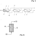
- Fig. 2 is a schematic explanatory diagram of a pretreatment device 4 installed upstream of the membrane module 1.
- a layer 5 filled with particles made of the same type of zeolite as the zeolite membrane 2 is arranged inside the pretreatment device 4. Causing the fluid to be treated 10 to pass through the particle filled layer 5 and come into contact with the zeolite particles destroys the zeolite forming the particles and the component generated by the destruction is contained in the fluid to be treated 10 and the fluid to be treated 10 is discharged as pretreated fluid 13. Since the pretreated fluid 13 passing the particle filled layer 5 contains the component of destroyed zeolite, the pretreated fluid 13 does not destroy the zeolite when coming into contact with the zeolite membrane 2 and desired membrane separation treatment is performed. Moreover, the life of the zeolite membrane 2 can be increased.
- the fluid to be treated is made to destroy the zeolite particles and contain the destroyed component as it is.
- the fluid to be treated that comes into contact with the zeolite membrane thereby contains components in the same composition ratio as the components forming the zeolite membrane.
- An effect of the fluid to be treated damaging, breaking, or destroying the zeolite forming membrane can be thus made as small as possible when the fluid to be treated comes into contact with the zeolite membrane.
- the fluid to be treated is made to destroy the zeolite particles and thereby contain silicon, aluminum, and cations forming the zeolite in the same composition ratio in a large amount. Accordingly, damage, breaking, or destruction of the zeolite membrane can be greatly suppressed when the fluid to be treated comes into contact with the zeolite membrane in a later step.
- contact time of the liquid mixture and the zeolite particles is preferably 60 to 600 seconds, more preferably 60 to 300 seconds. Setting the contact time within such a range can prevent destruction of the zeolite membrane without a decrease in treatment efficiency of the fluid to be treated.
- the contact time of the liquid mixture and the zeolite particles can be adjusted by adjusting: one or all of the cross-sectional area of the layer filled with the particles, the height of this layer, and the diameter of the particles; the number of baffles provided substantially orthogonal to a direction of flow of the fluid to be treated in the particle filled layer; or the length of substantial flow passages in the particle filled layer.
- contact time of the gas mixture and the zeolite particles is preferably 1 to 60 seconds, more preferably 1 to 5 seconds. Setting the contact time within such a range can prevent destruction of the zeolite membrane without a decrease in the treatment efficiency of the fluid to be treated.
- the contact time of the solid mixture and the zeolite particles can be adjusted by adjusting: one or all of the cross-sectional area of the layer filled with the particles, the height of this layer, and the diameter of the particles; the number of baffles provided substantially orthogonal to a direction of flow of the fluid to be treated in the particle filled layer; or the length of substantial flow passages in the particle filled layer.
- ethanol and water were mixed at a weight ratio of 85/15 and each of compounds of formic acid, butyric acid, 3-methyl-1-butanol, dimethyl sulfide, and nitric acid was mixed into the mixture of ethanol and water as an impurity at an impurity concentration of 500 ppm.
- a fluid to be treated containing no impurities was prepared for comparison.
- Fig. 3 schematically illustrates the pretreatment device 4.
- the pretreatment device 4 is formed of a container 15 having the particle filled layer 5 whose inside is filled with the zeolite particles.
- the pretreatment device 4 has a supply port 16 which is provided in a lower portion of the container 15 and through which the fluid to be treated 10 flows in and a discharge port 17 which is provided in an upper portion of the container 15 and through which the pretreated fluid 10 flows out.
- a partition plate 18 is arranged above the supply port 14 in the container 10 and the particle filled layer 5 made of zeolite particles is formed above the partition plate 18. Multiple small holes that allow only the fluid to be treated 10 to pass are opened in the partition plate 18.
- a buffer phase 19 for preventing entrance of the fluid to be treated 10 into the particle filled layer 5 in an uneven flow state is formed below the partition plate 18.
- the residence time of the fluid to be treated 10 can be adjusted by changing the height of the particle filled layer 5 (height from an upper surface of the partition plate 18 to an upper surface of the particle filled layer 5) and a supply flow rate of the fluid to be treated 10.
- the height of the particle filled layer 5 can be adjusted by adjusting the fill amount of the zeolite particles (granulated bodies containing NaA zeolite, product name A-4, produced by Tosoh Corporation, average particle size 6 mm).
- the residence time was set by combining the height of the particle filled layer 5 and the supply flow rate of the fluid to be treated 10 as illustrated in Table 1.
- Measurement results of the Na ion concentrations in the fluids to be treated subjected to no pretreatment (residence time was 0 seconds) and the pretreated fluids (residence times were 5 to 371 seconds) passing the pretreatment device with the residence time varied are illustrated in Table 2 for the blank and the fluids to be treated containing the impurities.
- the Na ion concentrations in the case where the blank was pretreated were the lowest and the Na ion concentrations in the case where the fluids to be treated containing 3-methyl-1-butanol and DMS were pretreated were the lowest next to the pretreated blank. Meanwhile, the Na ion concentrations were high in the fluids containing acid substances of formic acid, nitric acid, and butyric acid as the impurities.
- solubility equilibrium is a solubility equilibrium value at which Na ions in a fluid to be treated with water concentration of 15% by weight can be emitted in a stable state without destroying fillers made of NaA zeolite particles. Meanwhile, it can be assumed that this solubility equilibrium is altered when there is a hydrocarbon compound of 3-methyl-1-butanol or DMS or an acid substance of formic acid, nitric acid, or butyric acid in the fluid to be treated. Specifically, the following two considerations can be made.
- Second is assumption that electric charge in the water solution becomes uneven due to the hydrocarbon compound or the acid substance and the Na ions in the NaA zeolite, which do not dissolve in the pretreatment of the blank, dissolve to achieve equilibrium with respect to this unevenness and reach the equilibrium.
- a fluid to be treated obtained from an isopropanol refinement collection plant was isopropanol/water in a weight ratio of 90/10 (% by weight) and contained 500 ppm oxalic acid as an impurity.
- the pretreatment was performed by using the same pretreatment device as that in Example 1 under the condition where the residence time was 337 seconds.
- the pretreated fluid subjected to the pretreatment and the fluid to be treated not subjected to the pretreatment were subjected to dehydration treatment with the zeolite membrane and the levels of the performance decrease in the zeolite membrane were compared.
- the dehydration treatment was performed by a pervaporation method (PV method) using a NaA zeolite membrane with an effective membrane area of 14.5 cm 2 .
- PV method pervaporation method
- a batch dehydration method was performed at operation temperature of 110°C by using a liquid nitrogen trap with the permeation side set to vacuum pressure of 6 Torr.
- a charge amount was set to 300 ml.
- the dehydration was started after the operation temperature reached 110°C and the permeation amount (permeable flux) per unit time on the permeation side and the water concentration on the permeation side were measured every predetermined time.
- the zeolite membranes were prepared for the respective fluids and were continuously used without being replaced while the tests were repeatedly performed.
- a pump 6 fed the fluid to be treated 10 into the pretreatment device 4, including a predetermined amount of NaA zeolite particles, via a heater 7 at a supply flow rate of 2.4 g/min and the pretreated fluid 13 passing the pretreatment device 4 directly flowed into the membrane module 1 formed of a NaA zeolite membrane (having an effective membrane area of 14.5 cm 2 ) .
- the concentrated fluid 12 not permeating the NaA zeolite membrane was cooled by a cooler 8 and entered a concentration tank (not illustrated).
- Three types of pretreatment devices filled with 0 g, 0.5 g, and 1.0 g of NaA zeolite particles were prepared as the pretreatment devices and the dehydration treatment was performed in the aforementioned flow-type PV operation method. Continuous operation time required for the water concentration on the permeation side to reach or fall below 99.5% by weight was measured and set as breakthrough time to be used as a performance index of the zeolite membrane. The longer the breakthrough time is, the more the performance decrease of the zeolite membrane is suppressed.
- the breakthrough time for the dehydration treatment was about 3.3 hours and the permeating liquid flux was about 15 kg/m 2 h.
- the breakthrough time was about 17 hours and the permeating liquid flux was about 12.6 kg/m 2 h. It can be seen that the higher the concentration of water in the fluid to be treated is, the shorter the breakthrough time is, and the more likely the performance decrease of the zeolite membrane is to occur.
- the breakthrough time for the dehydration treatment was about 10 hours and the permeating liquid flux was about 15.3 kg/m 2 h.
- the breakthrough time was about 47 hours and the permeating liquid flux was about 11.1 kg/m 2 h.
- the breakthrough time was about 2.7 times longer than that in the case where the mixtures were not brought into contact with the NaA zeolite particles, and the performance decrease of the zeolite membrane was suppressed.
- the breakthrough time for the dehydration treatment was about 9.5 hours and the permeating liquid flux was about 16.2 kg/m 2 h.
- the breakthrough time was about 75 hours and the permeating liquid flux was about 13.4 kg/m 2 h.
- the breakthrough time was about 3 to 4.4 times longer than that in the case where the mixtures were not brought into contact with the NaA zeolite particles, and the performance decrease of the zeolite membrane was suppressed.
- a pretreatment device in which NaA zeolite particles were filled to height of 1 m was arranged upstream of a membrane module formed of a NaA zeolite membrane for a fluid to be treated containing isopropanol and water and was made to operate for about one year, that is about 8000 hours.
- the fluid to be treated contained approximately 90/10% by weight of isopropanol/water and contained about 500 ppm oxalic acid on average as an impurity.
- This fluid to be treated was vaporized by using a vaporizer and supplied to the pretreatment device in a vapor state at linear speed of 0.8 m/sec to perform the pretreatment.
- the amount of Na (in terms of Na 2 O oxide) in the unused NaA zeolite particles was about 17% by weight while the amount of Na (in terms of Na 2 O oxide) in the NaA zeolite particles used in the pretreatment was about 11 to 13% by weight.
- the amount of Na decreased by about 35% at maximum and it is assumed that Na flowed out by destruction of the zeolite particles.
- the Al 2 O 3 component was about 37% by weight
- the SiO 2 component was about 45% by weight
- the Al 2 O 3 /SiO 2 ratio was 0.84.
- the Al 2 O 3 component was about 45 to 46% by weight
- the SiO 2 component was about 42 to 43% by weight
- the Al 2 O 3 /SiO 2 ratio was 1.07 to 1.08. Since the Al 2 O 3 /SiO 2 ratio changed as described above, it can be said that the structure of the zeolite particles changed due to contact with the fluid to be treated. Specifically, it is assumed that electrical charge balance in the zeolite structure was altered due to removable of Na ions from the zeolite structure and at least part of zeolite was destroyed.
Landscapes
- Chemical & Material Sciences (AREA)
- Engineering & Computer Science (AREA)
- Chemical Kinetics & Catalysis (AREA)
- Water Supply & Treatment (AREA)
- Analytical Chemistry (AREA)
- General Chemical & Material Sciences (AREA)
- Oil, Petroleum & Natural Gas (AREA)
- Life Sciences & Earth Sciences (AREA)
- Inorganic Chemistry (AREA)
- Environmental & Geological Engineering (AREA)
- Geology (AREA)
- Health & Medical Sciences (AREA)
- Biomedical Technology (AREA)
- Organic Chemistry (AREA)
- Nanotechnology (AREA)
- Hydrology & Water Resources (AREA)
- Separation Using Semi-Permeable Membranes (AREA)
- Manufacturing & Machinery (AREA)
Applications Claiming Priority (2)
| Application Number | Priority Date | Filing Date | Title |
|---|---|---|---|
| JP2019089007A JP6733093B1 (ja) | 2019-05-09 | 2019-05-09 | ゼオライト膜に供する被処理流体の処理方法 |
| PCT/JP2019/029591 WO2020225931A1 (ja) | 2019-05-09 | 2019-07-29 | ゼオライト膜に供する被処理流体の処理方法 |
Publications (4)
| Publication Number | Publication Date |
|---|---|
| EP3967390A1 true EP3967390A1 (de) | 2022-03-16 |
| EP3967390A4 EP3967390A4 (de) | 2023-07-12 |
| EP3967390C0 EP3967390C0 (de) | 2025-10-15 |
| EP3967390B1 EP3967390B1 (de) | 2025-10-15 |
Family
ID=71738491
Family Applications (1)
| Application Number | Title | Priority Date | Filing Date |
|---|---|---|---|
| EP19927589.2A Active EP3967390B1 (de) | 2019-05-09 | 2019-07-29 | Behandlungsverfahren für eine zu behandelnde flüssigkeit, die einer zeolithmembran zugeführt wird |
Country Status (7)
| Country | Link |
|---|---|
| US (1) | US11090618B1 (de) |
| EP (1) | EP3967390B1 (de) |
| JP (1) | JP6733093B1 (de) |
| KR (1) | KR102267831B1 (de) |
| CN (1) | CN112118902A (de) |
| SG (1) | SG11202100090PA (de) |
| WO (1) | WO2020225931A1 (de) |
Family Cites Families (15)
| Publication number | Priority date | Publication date | Assignee | Title |
|---|---|---|---|---|
| US2924630A (en) * | 1957-06-28 | 1960-02-09 | Union Oil Co | Fluid diffusion fractionation |
| JPH09192650A (ja) * | 1996-01-16 | 1997-07-29 | Mitsubishi Rayon Co Ltd | 浄水器用濾過モジュール |
| CN1195578C (zh) * | 2003-05-15 | 2005-04-06 | 大连理工大学 | 沸石分子筛膜用于二氯乙烷和氮气混合物的分离方法 |
| DE10361508A1 (de) | 2003-12-23 | 2005-07-28 | Basf Ag | Verfahren zur Abreicherung von Schwefel und/oder schwefelhaltigen Verbindungen aus einer biochemisch hergestellten organischen Verbindung |
| JP4548080B2 (ja) * | 2004-10-04 | 2010-09-22 | 三菱化学株式会社 | 成分分離方法および成分分離装置 |
| US7897122B2 (en) * | 2005-02-14 | 2011-03-01 | Media And Process Technology | Hybrid adsorptive membrane reactor |
| JP2007055970A (ja) * | 2005-08-26 | 2007-03-08 | Mitsui Eng & Shipbuild Co Ltd | メタノール製造用反応器及びメタノール製造方法 |
| CN101259383B (zh) * | 2008-05-05 | 2012-05-23 | 江西师范大学 | 一种用于液体混合物分离的耐酸性沸石分子筛膜及其制备方法 |
| WO2012018007A1 (ja) | 2010-08-03 | 2012-02-09 | 三菱レイヨン株式会社 | メタノールの分離方法 |
| JP5584043B2 (ja) * | 2010-08-04 | 2014-09-03 | 三井造船株式会社 | 膜分離用前処理装置及びそれを用いた膜分離方法 |
| WO2013035849A1 (ja) * | 2011-09-09 | 2013-03-14 | 宝酒造株式会社 | 無水アルコールの製造方法、並びに、無水アルコール |
| WO2014115687A1 (ja) * | 2013-01-25 | 2014-07-31 | 住友ベークライト株式会社 | 浸透気化膜およびフェノール濃縮方法 |
| JP6730929B2 (ja) * | 2014-09-29 | 2020-07-29 | 日本碍子株式会社 | 分離方法及び分離装置 |
| JP6733091B2 (ja) * | 2015-04-21 | 2020-07-29 | 株式会社三井E&Sマシナリー | 脱水膜分離システムおよび脱水膜分離方法 |
| JP7164324B2 (ja) * | 2017-06-01 | 2022-11-01 | 三菱ケミカル株式会社 | 水素分離装置と水素分離方法 |
-
2019
- 2019-05-09 JP JP2019089007A patent/JP6733093B1/ja active Active
- 2019-07-29 US US17/055,823 patent/US11090618B1/en active Active
- 2019-07-29 EP EP19927589.2A patent/EP3967390B1/de active Active
- 2019-07-29 CN CN201980016362.0A patent/CN112118902A/zh active Pending
- 2019-07-29 WO PCT/JP2019/029591 patent/WO2020225931A1/ja not_active Ceased
- 2019-07-29 SG SG11202100090PA patent/SG11202100090PA/en unknown
- 2019-07-29 KR KR1020207022270A patent/KR102267831B1/ko active Active
Also Published As
| Publication number | Publication date |
|---|---|
| KR20200130244A (ko) | 2020-11-18 |
| JP6733093B1 (ja) | 2020-07-29 |
| EP3967390C0 (de) | 2025-10-15 |
| JP2020182917A (ja) | 2020-11-12 |
| KR102267831B1 (ko) | 2021-06-21 |
| EP3967390B1 (de) | 2025-10-15 |
| WO2020225931A1 (ja) | 2020-11-12 |
| CN112118902A (zh) | 2020-12-22 |
| EP3967390A4 (de) | 2023-07-12 |
| SG11202100090PA (en) | 2021-02-25 |
| US11090618B1 (en) | 2021-08-17 |
| US20210245113A1 (en) | 2021-08-12 |
Similar Documents
| Publication | Publication Date | Title |
|---|---|---|
| KR20130114616A (ko) | 초순수 제조장치 | |
| CN103687836B (zh) | 用于纯化醇的方法和装置 | |
| JP5911228B2 (ja) | 電極製造工程におけるnmp精製システム | |
| JP5617231B2 (ja) | イオン交換樹脂の精製方法及び精製装置 | |
| JP6228531B2 (ja) | 超純水製造装置及び超純水製造方法 | |
| CN102203017B (zh) | 即需即用间歇高净水生产系统 | |
| US9776892B2 (en) | Process for treating water with a counter-current ion exchange unit including silica and boron concentatration monitoring and regeneration thereof | |
| WO2018096700A1 (ja) | 超純水製造システム及び超純水製造方法 | |
| JP6228471B2 (ja) | 被処理水の処理装置、純水の製造装置および被処理水の処理方法 | |
| JP5584043B2 (ja) | 膜分離用前処理装置及びそれを用いた膜分離方法 | |
| JP6733091B2 (ja) | 脱水膜分離システムおよび脱水膜分離方法 | |
| JP4439674B2 (ja) | 脱イオン水製造装置 | |
| EP3967390B1 (de) | Behandlungsverfahren für eine zu behandelnde flüssigkeit, die einer zeolithmembran zugeführt wird | |
| CN212269740U (zh) | 一种超纯水制造系统 | |
| KR101036880B1 (ko) | 폐수 재이용 장치 및 상기 폐수 재이용 장치에 의해 제조된 재이용수를 이용하는 초순수의 제조방법 | |
| KR101695215B1 (ko) | Ipa 함유 폐수로부터 ipa의 농축 및 폐수처리를 위한 병합 막분리 공정 | |
| US20080264773A1 (en) | In vitro prophylactic on site ion-exchange purification process. | |
| WO2023067912A1 (ja) | 電極水の回収方法、及び超純水、もしくは製薬用水製造方法 | |
| JP5564817B2 (ja) | イオン交換樹脂の再生方法及び超純水製造装置 | |
| JP7660749B1 (ja) | 超純水製造方法、超純水製造装置及び超純水製造システム | |
| WO2010033817A2 (en) | Crude glycerol purification process | |
| KR102098748B1 (ko) | 내오염막과 해수용 역삼투막을 이용한 역삼투 농축수의 2차 농축 및 ed 시스템을 이용한 3차 농축 방법 | |
| JP5895962B2 (ja) | イオン交換樹脂のホウ素汚染防止方法 | |
| CN209890414U (zh) | 药用纯化水制备系统 | |
| JP4660890B2 (ja) | 電気脱イオン装置の運転方法 |
Legal Events
| Date | Code | Title | Description |
|---|---|---|---|
| STAA | Information on the status of an ep patent application or granted ep patent |
Free format text: STATUS: THE INTERNATIONAL PUBLICATION HAS BEEN MADE |
|
| PUAI | Public reference made under article 153(3) epc to a published international application that has entered the european phase |
Free format text: ORIGINAL CODE: 0009012 |
|
| STAA | Information on the status of an ep patent application or granted ep patent |
Free format text: STATUS: REQUEST FOR EXAMINATION WAS MADE |
|
| 17P | Request for examination filed |
Effective date: 20210114 |
|
| AK | Designated contracting states |
Kind code of ref document: A1 Designated state(s): AL AT BE BG CH CY CZ DE DK EE ES FI FR GB GR HR HU IE IS IT LI LT LU LV MC MK MT NL NO PL PT RO RS SE SI SK SM TR |
|
| DAV | Request for validation of the european patent (deleted) | ||
| DAX | Request for extension of the european patent (deleted) | ||
| RIN1 | Information on inventor provided before grant (corrected) |
Inventor name: MAEKAWA KAZUYA |
|
| RIC1 | Information provided on ipc code assigned before grant |
Ipc: B01D 53/22 20060101ALI20230503BHEP Ipc: B01D 15/12 20060101ALI20230503BHEP Ipc: B01D 61/36 20060101ALI20230503BHEP Ipc: B01D 61/16 20060101ALI20230503BHEP Ipc: B01D 71/02 20060101AFI20230503BHEP |
|
| RIC1 | Information provided on ipc code assigned before grant |
Ipc: B01D 53/22 20060101ALI20230512BHEP Ipc: B01D 15/12 20060101ALI20230512BHEP Ipc: B01D 61/36 20060101ALI20230512BHEP Ipc: B01D 61/16 20060101ALI20230512BHEP Ipc: B01D 71/02 20060101AFI20230512BHEP |
|
| RIC1 | Information provided on ipc code assigned before grant |
Ipc: B01D 53/22 20060101ALI20230601BHEP Ipc: B01D 15/12 20060101ALI20230601BHEP Ipc: B01D 61/36 20060101ALI20230601BHEP Ipc: B01D 61/16 20060101ALI20230601BHEP Ipc: B01D 71/02 20060101AFI20230601BHEP |
|
| A4 | Supplementary search report drawn up and despatched |
Effective date: 20230609 |
|
| RIC1 | Information provided on ipc code assigned before grant |
Ipc: B01D 53/22 20060101ALI20230602BHEP Ipc: B01D 15/12 20060101ALI20230602BHEP Ipc: B01D 61/36 20060101ALI20230602BHEP Ipc: B01D 61/16 20060101ALI20230602BHEP Ipc: B01D 71/02 20060101AFI20230602BHEP |
|
| RAP1 | Party data changed (applicant data changed or rights of an application transferred) |
Owner name: MITSUI E&S CO., LTD. |
|
| STAA | Information on the status of an ep patent application or granted ep patent |
Free format text: STATUS: EXAMINATION IS IN PROGRESS |
|
| 17Q | First examination report despatched |
Effective date: 20240617 |
|
| 17Q | First examination report despatched |
Effective date: 20240626 |
|
| GRAP | Despatch of communication of intention to grant a patent |
Free format text: ORIGINAL CODE: EPIDOSNIGR1 |
|
| STAA | Information on the status of an ep patent application or granted ep patent |
Free format text: STATUS: GRANT OF PATENT IS INTENDED |
|
| INTG | Intention to grant announced |
Effective date: 20250616 |
|
| GRAS | Grant fee paid |
Free format text: ORIGINAL CODE: EPIDOSNIGR3 |
|
| GRAA | (expected) grant |
Free format text: ORIGINAL CODE: 0009210 |
|
| STAA | Information on the status of an ep patent application or granted ep patent |
Free format text: STATUS: THE PATENT HAS BEEN GRANTED |
|
| AK | Designated contracting states |
Kind code of ref document: B1 Designated state(s): AL AT BE BG CH CY CZ DE DK EE ES FI FR GB GR HR HU IE IS IT LI LT LU LV MC MK MT NL NO PL PT RO RS SE SI SK SM TR |
|
| REG | Reference to a national code |
Ref country code: GB Ref legal event code: FG4D Ref country code: CH Ref legal event code: F10 Free format text: ST27 STATUS EVENT CODE: U-0-0-F10-F00 (AS PROVIDED BY THE NATIONAL OFFICE) Effective date: 20251015 |
|
| REG | Reference to a national code |
Ref country code: IE Ref legal event code: FG4D |
|
| U01 | Request for unitary effect filed |
Effective date: 20251018 |
|
| U07 | Unitary effect registered |
Designated state(s): AT BE BG DE DK EE FI FR IT LT LU LV MT NL PT RO SE SI Effective date: 20251024 |