EP3967167B1 - Rauchvorrichtung - Google Patents
Rauchvorrichtung Download PDFInfo
- Publication number
- EP3967167B1 EP3967167B1 EP20885998.3A EP20885998A EP3967167B1 EP 3967167 B1 EP3967167 B1 EP 3967167B1 EP 20885998 A EP20885998 A EP 20885998A EP 3967167 B1 EP3967167 B1 EP 3967167B1
- Authority
- EP
- European Patent Office
- Prior art keywords
- low
- temperature cigarette
- smoking device
- heating part
- heating
- Prior art date
- Legal status (The legal status is an assumption and is not a legal conclusion. Google has not performed a legal analysis and makes no representation as to the accuracy of the status listed.)
- Active
Links
Images


Classifications
-
- A—HUMAN NECESSITIES
- A24—TOBACCO; CIGARS; CIGARETTES; SIMULATED SMOKING DEVICES; SMOKERS' REQUISITES
- A24F—SMOKERS' REQUISITES; MATCH BOXES; SIMULATED SMOKING DEVICES
- A24F40/00—Electrically operated smoking devices; Component parts thereof; Manufacture thereof; Maintenance or testing thereof; Charging means specially adapted therefor
- A24F40/40—Constructional details, e.g. connection of cartridges and battery parts
- A24F40/46—Shape or structure of electric heating means
- A24F40/465—Shape or structure of electric heating means specially adapted for induction heating
-
- A—HUMAN NECESSITIES
- A24—TOBACCO; CIGARS; CIGARETTES; SIMULATED SMOKING DEVICES; SMOKERS' REQUISITES
- A24F—SMOKERS' REQUISITES; MATCH BOXES; SIMULATED SMOKING DEVICES
- A24F40/00—Electrically operated smoking devices; Component parts thereof; Manufacture thereof; Maintenance or testing thereof; Charging means specially adapted therefor
- A24F40/50—Control or monitoring
-
- A—HUMAN NECESSITIES
- A24—TOBACCO; CIGARS; CIGARETTES; SIMULATED SMOKING DEVICES; SMOKERS' REQUISITES
- A24F—SMOKERS' REQUISITES; MATCH BOXES; SIMULATED SMOKING DEVICES
- A24F40/00—Electrically operated smoking devices; Component parts thereof; Manufacture thereof; Maintenance or testing thereof; Charging means specially adapted therefor
- A24F40/60—Devices with integrated user interfaces
-
- A—HUMAN NECESSITIES
- A24—TOBACCO; CIGARS; CIGARETTES; SIMULATED SMOKING DEVICES; SMOKERS' REQUISITES
- A24F—SMOKERS' REQUISITES; MATCH BOXES; SIMULATED SMOKING DEVICES
- A24F40/00—Electrically operated smoking devices; Component parts thereof; Manufacture thereof; Maintenance or testing thereof; Charging means specially adapted therefor
- A24F40/90—Arrangements or methods specially adapted for charging batteries thereof
-
- A—HUMAN NECESSITIES
- A24—TOBACCO; CIGARS; CIGARETTES; SIMULATED SMOKING DEVICES; SMOKERS' REQUISITES
- A24D—CIGARS; CIGARETTES; TOBACCO SMOKE FILTERS; MOUTHPIECES OF CIGARS OR CIGARETTES; MANUFACTURE OF TOBACCO SMOKE FILTERS OR MOUTHPIECES
- A24D1/00—Cigars; Cigarettes
- A24D1/20—Cigarettes specially adapted for simulated smoking devices
-
- A—HUMAN NECESSITIES
- A24—TOBACCO; CIGARS; CIGARETTES; SIMULATED SMOKING DEVICES; SMOKERS' REQUISITES
- A24F—SMOKERS' REQUISITES; MATCH BOXES; SIMULATED SMOKING DEVICES
- A24F40/00—Electrically operated smoking devices; Component parts thereof; Manufacture thereof; Maintenance or testing thereof; Charging means specially adapted therefor
- A24F40/20—Devices using solid inhalable precursors
Definitions
- the present disclosure relates to a smoking device, belonging to the technical field of low-temperature cigarettes.
- Low-temperature cigarettes are also called heat-not-burn tobacco products, which are different from traditional cigarettes that produce smoke by burning the tobacco itself.
- the tobacco of low-temperature cigarettes does not burn itself, but is heated by a heater, so that the nicotine therein is released in the form of smoke for smoking, such that a physiological sense of pleasure can be produced.
- the heating temperature of low-temperature cigarettes is lower than the burning temperature of traditional cigarettes, it can significantly reduce the large amount of harmful substances produced by the combustion of low-temperature cigarettes, and reduce the harm of passive smoking to non-smokers. Therefore, the harm of low-temperature cigarettes to the human body is much lower than the traditional direct-burn cigarettes.
- Existing low-temperature cigarette electric heating devices are mainly divided into two types, central heating and peripheral heating.
- the central heating means that the heating device is inserted into the low-temperature cigarette, and the tobacco (shredded tobacco) is heated to produce smoke.
- the heating device and the tobacco in the low-temperature cigarette produce adhesion and compaction, so when the low-temperature cigarette is smoked, the tobacco is likely to fall off and stay in the heating device.
- Smoking devices are known from the following publications: CN 208 863 592 U , CN 209 202 162 U , CN 107 373 761 A or CN 108 402 526 A .
- the present disclosure is intended to provide a smoking device, such that reduce the adhesion and/or compaction between the tobacco substance in the low-temperature cigarette and the heating part, and reduce the risk of falling of the material (tobacco and/or tobacco leaf) when extracting (pulling out of) the low-temperature cigarette, making it easier to separate the heating part from the tobacco material.
- the present disclosure provides a smoking device, including a housing, a receiving part for accommodating a low-temperature cigarette, and a heating part for heating the low-temperature cigarette; the receiving part is provided in the housing, and the receiving part is provided with a cavity for accommodating the low-temperature cigarette; a top of the heating part penetrates a bottom of the receiving part and extends inside the receiving part; wherein,
- a bottom of the heating part is connected to a first end of a handle, and a second end of the handle extends out of the housing through a window, the window is provided on a side wall of the housing.
- the handle when the low-temperature cigarette needs to be extracted, the handle is rotated so that the heating part is driven by the handle to rotate.
- the bottom of the heating part is connected to an output shaft of a motor, the motor is connected to a control board, and the control board is configured to control activation and/or deactivation of the motor; the motor and the control board are both provided inside the housing.
- control board when the low-temperature cigarette needs to be extracted, the control board sends a driving signal to drive the motor to rotate, so that the heating part is driven by the motor to rotate.
- the output shaft of the motor is connected to the bottom of the heating part through a transmission part.
- the transmission part comprises a coupling, a driving end of the coupling is connected with the output shaft of the motor, and a driven end of the coupling is connected with the bottom of the heating part.
- the transmission part further comprises a driving gear and a driven gear engaged with the driving gear; the driving gear is connected with the output shaft of the motor, the driven gear is connected to the bottom of the heating part.
- the output shaft of the motor is connected to the driving gear through a reducer.
- the transmission part further comprises a belt transmission mechanism or a chain transmission mechanism.
- the heating part is configured as a resistance heating element or an infrared heating element.
- a plurality of electrical contact points are provided at a bottom of the resistance heating element or the infrared heating element, each electrical contact point is connected to a battery part through a wire, and the battery part is provided inside the housing.
- the each electrical contact point is connected to the control board through the wire, the control board is electrically connected to the battery part; the control board is configured for controlling ON/OFF of a circuit heated by the resistance heating element or the infrared heating element.
- the electrical contact point is connected to a first end of the wire through an elastic electrical connection joint, and a second end of the wire is connected to the control board; wherein, a first end of the elastic electrical connection joint is in contact with the electrical contact point, and a second end of the elastic electrical connection joint is connected to the side wall of the housing through a spring.
- a first end of the spring is firmly connected to the side wall of the housing, and a second end of the spring is provided in a groove at the second end of the elastic electrical connection joint.
- the heating part is configured as an electromagnetic induction heating element; the electromagnetic induction heating element heats the low-temperature cigarette through electromagnetic induction eddy current.
- the receiving part is provided with at least one limiting portion on an inner wall; the at least one limiting portion is used to fix the low-temperature cigarette inside the receiving part, and to prevent the low-temperature cigarette from rotating.
- the at least one limiting portion comprises a protrusion and/or a limiting position.
- the low-temperature cigarette when the low-temperature cigarette is inserted into the receiving part, the low-temperature cigarette is deformed, and a friction is generated between the low-temperature cigarette and the receiving part, so that the low-temperature cigarette is fixed inside the receiving part and unable to rotated.
- a friction generated between the heating part and the low-temperature cigarette is smaller than the friction generated between the low-temperature cigarette and the receiving part, causing the heating part and the low-temperature cigarette to rotate relative to each other, thereby separating the heating part from the tobacco substances in the low-temperature cigarette.
- the at least one limiting portion is provided in a strip shape, and the at least one limiting portion extends from a top of the receiving part to the bottom of the receiving part.
- a plurality of the limiting portions are provided at intervals.
- the heating part has a rotation angle of 0-360 degrees, or greater than 360 degrees.
- the heating part has a cross section in a circular shape, an oval shape or a polygon shape.
- control board is provided with a charging interface; the charging interface is used to charge the battery part.
- the housing is provided with a control button on the side wall, and the control board is connected to the battery part through the control button.
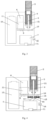
- the smoking device provided by the present disclosure may include a housing 1, a receiving part 3 for a accommodating low-temperature cigarette 2 and a heating part 4 for heating the low-temperature cigarette 2.
- the receiving part 3 is provided in the housing 1, and a cavity for accommodating low-temperature cigarette is provided in the receiving part 3.
- the top of the heating part 4 penetrates the bottom of the receiving part 3 and extends into the interior of the receiving part 3. Wherein, when the low-temperature cigarette 2 needs to be heated, the heating part 4 is inserted inside the low-temperature cigarette 2 to heat the low-temperature cigarette 2.
- the heating part 4 is rotated to make the heating part 4 and the low-temperature cigarette 2 rotate relative to each other, so that the heating part 4 can be separated from the tobacco material 21 (tobacco and/or tobacco leaves) in the low-temperature cigarette 2. It should be noted that separation includes the relative change of the position of the low-temperature cigarette 2 and the heating part 4, or the removal of the adhesion and/or compaction state between the low-temperature cigarette 2 and the heating part 4 due to heating and carbonization.
- the relative movement of the heating part 4 and the low-temperature cigarette 2 before the extraction of the low-temperature cigarette 2 can reduce the adhesion and/or compaction between the tobacco material 21 and the heating part 4, and reduce the risk of tobacco material 21 falling on the receiving part 3 when the low-temperature cigarette 2 is extracted, and can make the heating part 4 and the tobacco substance 21 easy to separate.
- the bottom of the heating part 4 is connected to the first end of the handle 5, and the second end of the handle 5 extends to the outside of the housing 1 through a window, and the window is provided on the side wall of the housing 1.
- the size of the window defines the rotation angle of the handle 5, thereby indirectly restricts the rotation angle of the heating part 4.
- the handle 5 when the low-temperature cigarette 2 needs to be extracted, the handle 5 is rotated, and the handle 5 drives the heating part 4 to rotate, so that the heating part 4 and the low-temperature cigarette 2 rotate relative to each other, thereby making the heating part 4 separated from the tobacco substance 21 in the low-temperature cigarette 2.
- the handle 5 By rotating the handle 5 to drive the heating part 4 to rotate, the structure is simple.
- the bottom of the heating part 4 is connected to the output shaft of the motor 6, the motor 6 is electrically connected to the control board 7, and the control board 7 can control activation (rotation) and/ or deactivation (stop) of the motor 6. It has high degree of intelligence, good flexibility. Both the motor 6 and the control board 7 are provided inside the housing 1.
- the control board 7 sends a drive signal to drive the motor 6 to rotate, and the motor 6 drives the heating part 4 to rotate, so that the heating part 4 and the low-temperature cigarette 2 rotates relative to each other, thereby separating the heating part 4 from the tobacco substance 21 in the low-temperature cigarette 2.
- the heating part 4 is driven to rotate by driving the motor 6, which is convenient to use.
- the output shaft of the motor 6 is connected to the bottom of the heating part 4 through a transmission part.
- the transmission part includes a coupling 8.
- the driving end of the coupling 8 is connected to the output shaft of the motor 6, and the driven end of the coupling 8 is connected to the bottom of the heating part 4, enabling the heating part 4 and the motor 6 to rotate synchronously.
- the transmission by the coupling can reduce the vibration of the mechanical transmission and reduce the impact peak load. At the same time, it has a certain degree of cushioning and shock absorption performance and overload safety protection.
- the transmission part further includes a driving gear 9 and a driven gear 10 engaged with the driving gear 9.
- the driving gear 9 is connected to the output shaft of the motor 6, and the driven gear 10 is connected to the bottom of the heating part 4.
- Gear transmission can facilitate deceleration or acceleration, it has a high carrying capacity, high transmission efficiency, and good stability.
- the output shaft of the motor 6 is connected to the driving gear 9 through a reducer 11.
- the reducer 11 can effectively reduce the rotation speed of the motor 6, thereby increasing the stability of rotation by heating part 4.
- the transmission part further includes a belt transmission mechanism or a chain transmission mechanism.
- the belt transmission mechanism includes a first pulley and a second pulley, and the first pulley and the second pulley are connected by a belt.
- the first pulley is connected to the output shaft of the motor 6, and the second pulley is connected to the bottom of the heating part 4.
- the belt transmission has the advantages of cushioning impact, absorbing vibration, low noise, low cost and convenient maintenance.
- the chain transmission mechanism includes a first sprocket and a second sprocket, and the first sprocket and the second sprocket are connected by a chain.
- the first sprocket is connected with the output shaft of the motor 6, and the second sprocket is connected with the bottom of the heating part 4.
- the chain transmission has no elastic sliding and slipping phenomenon, the average transmission ratio is accurate, the work is reliable, the efficiency is high, and the overload capacity is strong.
- the rotation angle of the heating part 4 is 0 to 360 degrees, or the rotation angle of the heating part 4 is greater than 360 degrees.
- the rotation mode of the heating part 4 is set to be forward and reverse cyclic rotation, and the rotation angle of the heating part 4 is greater than 0 degrees and less than 360 degrees.
- the heating part 4 is configured as a resistance heating element or an infrared heating element, such that the temperature can be quickly risen, it has good controllability.
- the bottom of the resistance heating element or the infrared heating element is provided with a plurality of electrical contact points 41, and each of the electrical contact points 41 is connected to the battery part 13 through a wire 12.
- the battery part 13 is provided inside the housing 1.
- the wire 12 is a flexible wire that can be bent.
- the flexible wire is made of a material that has high toughness and can be repeatedly bent. When the heating part 4 rotates in the forward direction, the flexible wire deforms, and when it rotates in the reverse direction, the flexible wire returns to the original state.
- the electrical contact point 41 is connected to the control board 7 through the wire 12, and the control board 7 is electrically connected to the battery part 13.
- the control board 7 can control the connection (ON) or disconnection (OFF) of the circuit heated by the resistance heating element or by the infrared heating element. It has a high degree of intelligence and flexibility. When the circuit heated by the resistance heating element or the infrared heating element is connected, the resistance heating element or the infrared heating element generates heat and can heat the low-temperature cigarette 2. When the circuit heated by the resistance heating element or the infrared heating element is disconnected, the resistance heating element or the infrared heating element does not generate heat.
- the electrical contact point 41 is connected to the first end of the wire 12 through the elastic electrical connection joint 14, and the second end of the wire 12 is connected to the control board 7.
- the first end of the elastic electrical connection joint 14 is in contact with the electrical contact point 41
- the second end of the elastic electrical connection joint 14 is connected to the side wall of the housing 1 through the spring 15.
- the first end of the spring 15 is firmly connected to the side wall of the housing 1, and the second end of the spring 15 is provided in the groove at the second end of the elastic electrical connection joint 14.
- the heating part 4 is configured as an electromagnetic induction heating element, such that it can quickly heat up, and cause heat to be concentrated inside the electromagnetic induction heating element, with minimal external heat dissipation, high thermal efficiency, and significant energy-saving effects.
- electromagnetic induction heating uses electromagnetic induction eddy currents to heat low-temperature cigarettes.
- a limiting portion 31 is provided on the inner wall of the receiving part 3 for fixing the low-temperature cigarette 2 inside the receiving part 3 and for preventing the low-temperature cigarette 2 from rotating.
- the limiting portion 31 includes at least one protrusion and/or at least one limiting position.
- the low-temperature cigarette 2 when the low-temperature cigarette 2 is inserted into the receiving part 3, the low-temperature cigarette 2 is deformed, and a friction is generated between the low-temperature cigarette 2 and the receiving part 3.
- the low-temperature cigarette 2 can be fixed inside the receiving part 3 and cannot be rotated.
- the friction force generated between the heating part 4 and the low-temperature cigarette 2 is less than the friction force generated between the low-temperature cigarette 2 and the receiving part 3, so that the heating part 4 and the low-temperature cigarette 2 can rotate relative to each other, thereby separating the heating part 4 from the tobacco substance 21 in the low-temperature cigarette 2.
- the limiting portion 31 is provided in a strip shape, and the limiting portion 31 extends from the top of the receiving part 3 to the bottom of the receiving part 3.
- a plurality of the limiting portions 31 are provided at intervals, making the low-temperature cigarette 2 uniformly deform, and good stability can be achieved.
- the cross section of the heating part 4 is set to be circular, oval or polygonal.
- a charging interface 71 is provided on the control board 7 for charging the battery part 13, so that the battery part 13 can be used continuously.
- a control button 16 is provided on the side wall of the housing 1, and the control board 7 is connected to the battery part 13 through the control button 16. Specifically, when the control button 16 is turned on, the battery part 13 supplies power to the heating unit 4. When the control button 16 is turned off, the battery part 13 stops supplying power to the heating unit 4.
- the heating part 4 heats the tobacco section of the low-temperature cigarette 2.
- the heating part 4 When the present disclosure is used, and when the low-temperature cigarette 2 needs to be heated, the heating part 4 is inserted inside the tobacco section of the low-temperature cigarette 2 to heat the tobacco substance 21.
- the heating part 4 is driven to rotate by rotating the handle 5 (as shown in FIG. 1 ) or by driving the motor 6 (as shown in FIGS. 2 to 4 ) to rotate, so that the heating part 4 can rotate relative to the low-temperature cigarette 2, making the heating part 4 separated from the tobacco substance 21 in the low-temperature cigarette 2.
Landscapes
- Engineering & Computer Science (AREA)
- Human Computer Interaction (AREA)
- Toys (AREA)
- Central Heating Systems (AREA)
- Manufacturing Of Cigar And Cigarette Tobacco (AREA)
Claims (22)
- Rauchvorrichtung, umfassend ein Gehäuse, ein Aufnahmeteil zum Aufnehmen einer Niedertemperatur-Zigarette und ein Heizteil zum Erhitzen der Niedertemperatur-Zigarette;wobei das Aufnahmeteil in dem Gehäuse vorgesehen ist und das Aufnahmeteil mit einem Hohlraum zum Aufnehmen der Niedertemperatur-Zigarette im Inneren des Aufnahmeteils versehen ist;ein oberes Ende des Heizteils eine Unterseite des Aufnahmeteils durchdringt und sich in das Innere des Aufnahmeteils erstreckt; wobei,wenn die Niedertemperatur-Zigarette erhitzt werden muss, das Heizteil in das Innere von der Niedertemperatur-Zigarette eingeführt wird, um die Niedertemperatur-Zigarette zu erhitzen; undwenn die Niedertemperatur-Zigarette herausgezogen werden muss, das Heizteil gedreht wird, um das Heizteil relativ zu der Niedertemperatur-Zigarette derart sich drehen zu lassen, dass das Heizteil von den Tabaksubstanzen in der Niedertemperatur-Zigarette getrennt wird; wobeider Heizteil als ein Widerstandsheizelement oder ein Infrarotheizelement konfiguriert ist; eine Vielzahl von elektrischen Kontaktpunkten an einer Unterseite des Widerstandsheizelements oder des Infrarotheizelements vorgesehen ist, jeder elektrische Kontaktpunkt mit einem Batterieteil durch einen Draht verbunden ist, und der Batterieteil innerhalb des Gehäuses vorgesehen ist, jeder elektrische Kontaktpunkt mit der Steuerplatine durch den Draht verbunden ist, die Steuerplatine elektrisch mit dem Batterieteil verbunden ist; die Steuerplatine zum Steuern von EIN/AUS eines durch das Widerstandsheizelement oder das Infrarotheizelement beheizten Schaltkreises konfiguriert ist, der elektrische Kontaktpunkt mit einem ersten Ende des Drahtes durch einen elastischen elektrischen Verbindungsanschluss verbunden ist und ein zweites Ende des Drahtes mit der Steuerplatine verbunden ist;wobei ein erstes Ende des elastischen elektrischen Verbindungsanschlusses in Kontakt mit dem elektrischen Kontaktpunkt ist und ein zweites Ende des elastischen elektrischen Verbindungsanschlusses mit der Seitenwand des Gehäuses durch eine Feder verbunden ist, wobei die Rauchvorrichtung ferner dadurch gekennzeichnet ist, dass der Drehmodus des Heizteils auf eine zyklische Vorwärts- und Rückwärtsdrehbewegung eingestellt ist; der Draht ein biegsamer Draht ist, der gebogen werden kann, wobei der biegsame Draht aus einem Material hergestellt ist, das eine hohe Zähigkeit aufweist und wiederholt gebogen werden kann.
- Rauchvorrichtung nach Anspruch 1, wobei eine Unterseite des Heizteils mit einem ersten Ende eines Griffs verbunden ist und ein zweites Ende des Griffs sich durch ein Fenster aus dem Gehäuse heraus erstreckt, wobei das Fenster an einer Seitenwand des Gehäuses vorgesehen ist.
- Rauchvorrichtung nach Anspruch 2, wobei, wenn die Niedertemperatur-Zigarette herausgezogen werden muss, der Griff gedreht wird, sodass das Heizteil durch den Griff zum Drehen angetrieben wird.
- Rauchvorrichtung nach Anspruch 1, wobei die Unterseite des Heizteils mit einer Abtriebswelle eines Motors verbunden ist, der Motor mit einer Steuerplatine verbunden ist und die Steuerplatine so konfiguriert ist, dass sie die Aktivierung und/oder die Deaktivierung des Motors steuert; der Motor und die Steuerplatine beide innerhalb des Gehäuses vorgesehen sind.
- Rauchvorrichtung nach Anspruch 4, wobei, wenn die Niedertemperatur-Zigarette herausgezogen werden muss, die Steuerplatine ein Antriebssignal sendet, um den Motor zum Drehen anzutreiben, sodass das Heizteil durch den Motor zum Drehen angetrieben wird.
- Rauchvorrichtung nach Anspruch 4, wobei die Abtriebswelle des Motors mit der Unterseite des Heizteils durch ein Übertragungsteil verbunden ist.
- Rauchvorrichtung nach Anspruch 6, wobei das Übertragungsteil eine Kupplung umfasst, wobei ein antreibendes Ende der Kupplung mit der Abtriebswelle des Motors verbunden ist und ein angetriebenes Ende der Kupplung mit der Unterseite des Heizteils verbunden ist.
- Rauchvorrichtung nach Anspruch 6, wobei das Übertragungsteil ferner ein Antriebszahnrad und ein mit dem Antriebszahnrad in Eingriff stehendes Abtriebszahnrad umfasst; das Antriebszahnrad mit der Abtriebswelle des Motors verbunden ist, wobei das Abtriebszahnrad mit der Unterseite des Heizteils verbunden ist.
- Rauchvorrichtung nach Anspruch 8, wobei die Abtriebswelle des Motors mit dem Antriebszahnrad über ein Untersetzungsgetriebe verbunden ist.
- Rauchvorrichtung nach Anspruch 6, wobei das Übertragungsteil ferner einen Riemen-Übertragungsmechanismus oder einen Ketten-Übertragungsmechanismus umfasst.
- Rauchvorrichtung nach Anspruch 1, wobei ein erstes Ende der Feder fest mit der Seitenwand des Gehäuses verbunden ist und ein zweites Ende der Feder in einer Nut an dem zweiten Ende des elastischen elektrischen Verbindungsanschlusses vorgesehen ist.
- Rauchvorrichtung nach Anspruch 4, wobei das Heizteil als ein elektromagnetisches Induktionsheizelement konfiguriert ist; wobei das elektromagnetische Induktionsheizelement die Niedertemperatur-Zigarette durch elektromagnetischen Induktionswirbelstrom erwärmt.
- Rauchvorrichtung nach Anspruch 1, wobei das Aufnahmeteil mit mindestens einem Begrenzungsabschnitt an einer Innenwand versehen ist; der mindestens eine Begrenzungsabschnitt verwendet wird, um die Niedertemperatur-Zigarette im Inneren des Aufnahmeteils zu fixieren und um zu verhindern, dass sich die Niedertemperatur-Zigarette dreht.
- Rauchvorrichtung nach Anspruch 13, wobei der mindestens eine Begrenzungsabschnitt einen Vorsprung und/oder eine Begrenzungsposition aufweist.
- Rauchvorrichtung nach Anspruch 13, wobei, wenn die Niedertemperatur-Zigarette in das Aufnahmeteil eingeführt wird, die Niedertemperatur-Zigarette verformt wird und eine Reibung zwischen der Niedertemperatur-Zigarette und dem Aufnahmeteil erzeugt wird, sodass die Niedertemperatur-Zigarette innerhalb des Aufnahmeteils fixiert ist und nicht in der Lage ist, sich zu drehen.
- Rauchvorrichtung nach Anspruch 15, wobei, wenn sich das Heizteil dreht, eine zwischen dem Heizteil und der Niedertemperatur-Zigarette erzeugte Reibung kleiner ist als die zwischen der Niedertemperatur-Zigarette und dem Aufnahmeteil erzeugte Reibung, wodurch das Heizteil und die Niedertemperatur-Zigarette veranlasst werden, sich relativ zueinander zu drehen, wodurch das Heizteil von den Tabaksubstanzen in der Niedertemperatur-Zigarette getrennt wird.
- Rauchvorrichtung nach Anspruch 13, wobei der mindestens eine Begrenzungsabschnitt in einer Streifenform ausgebildet ist und sich der mindestens eine Begrenzungsabschnitt von einer Oberseite des Aufnahmeteils zu der Unterseite des Aufnahmeteils hin erstreckt.
- Rauchvorrichtung nach Anspruch 17, wobei eine Vielzahl der Begrenzungsabschnitte in Abständen vorgesehen sind.
- Rauchvorrichtung nach Anspruch 1, wobei der Heizteil einen Drehwinkel von 0 bis 360 Grad oder mehr als 360 Grad aufweist.
- Rauchvorrichtung nach Anspruch 1, wobei das Heizteil einen Querschnitt in einer kreisförmigen Form, einer ovalen Form oder einer polygonalen Form aufweist.
- Rauchvorrichtung nach Anspruch 1, wobei die Steuerplatine mit einer Ladeschnittstelle versehen ist; die Ladeschnittstelle zum Laden des Batterieteils verwendet wird.
- Rauchvorrichtung nach Anspruch 1, wobei das Gehäuse mit einem Steuerknopf an der Seitenwand versehen ist und die Steuerplatine über den Steuerknopf mit dem Batterieteil verbunden ist.
Applications Claiming Priority (2)
| Application Number | Priority Date | Filing Date | Title |
|---|---|---|---|
| CN201911068843.4A CN112369682A (zh) | 2019-11-05 | 2019-11-05 | 一种吸烟装置 |
| PCT/CN2020/123680 WO2021088673A1 (zh) | 2019-11-05 | 2020-10-26 | 一种吸烟装置 |
Publications (3)
| Publication Number | Publication Date |
|---|---|
| EP3967167A1 EP3967167A1 (de) | 2022-03-16 |
| EP3967167A4 EP3967167A4 (de) | 2022-12-21 |
| EP3967167B1 true EP3967167B1 (de) | 2024-12-11 |
Family
ID=74585984
Family Applications (1)
| Application Number | Title | Priority Date | Filing Date |
|---|---|---|---|
| EP20885998.3A Active EP3967167B1 (de) | 2019-11-05 | 2020-10-26 | Rauchvorrichtung |
Country Status (5)
| Country | Link |
|---|---|
| EP (1) | EP3967167B1 (de) |
| KR (1) | KR102743150B1 (de) |
| CN (1) | CN112369682A (de) |
| PH (1) | PH12021552651B1 (de) |
| WO (1) | WO2021088673A1 (de) |
Families Citing this family (7)
| Publication number | Priority date | Publication date | Assignee | Title |
|---|---|---|---|---|
| CN215347059U (zh) * | 2021-04-15 | 2021-12-31 | 深圳市合元科技有限公司 | 气溶胶生成装置以及红外加热器 |
| WO2023070269A1 (en) * | 2021-10-25 | 2023-05-04 | Philip Morris Products S.A. | Heating assembly for aerosol-generating device |
| CN116473298B (zh) * | 2022-01-17 | 2026-01-30 | 深圳市凯利健康科技有限公司 | 一种手持烤烟器 |
| US20250311771A1 (en) * | 2022-05-10 | 2025-10-09 | Shenzhen First Union Technology Co., Ltd. | Aerosol generation device and control method |
| CN115886359A (zh) * | 2023-02-06 | 2023-04-04 | 湖北中烟工业有限责任公司 | 一种具有可转动加热元件的气溶胶生成装置 |
| CN117256942A (zh) * | 2023-10-26 | 2023-12-22 | 云南中烟工业有限责任公司 | 一种螺旋插入式电磁加热烟具及使用方法 |
| CN117694618A (zh) * | 2024-01-18 | 2024-03-15 | 湖北中烟工业有限责任公司 | 一种具有可转动加热元件的加热器具 |
Family Cites Families (15)
| Publication number | Priority date | Publication date | Assignee | Title |
|---|---|---|---|---|
| US9943112B2 (en) * | 2014-05-28 | 2018-04-17 | Huizhou Kimree Technology Co., Ltd. Shenzhen Branch | Electronic cigarette having a bottle configured for storing the tobacco oil |
| CN209768983U (zh) * | 2016-06-07 | 2019-12-13 | 惠州市吉瑞科技有限公司深圳分公司 | 一种雾化组件 |
| KR20180070451A (ko) * | 2016-12-16 | 2018-06-26 | 주식회사 케이티앤지 | 에어로졸 형성기질을 가열하기 위한 히터 및 시스템 |
| CN107373761A (zh) * | 2017-07-14 | 2017-11-24 | 中国健康养生集团有限公司 | 一种一次性烟弹 |
| CN111031819B (zh) * | 2017-08-09 | 2023-07-18 | 菲利普莫里斯生产公司 | 具有可移除的感受器的气溶胶生成装置 |
| CN109965353B (zh) * | 2017-12-28 | 2024-06-14 | 湖南中烟工业有限责任公司 | 低温烘焙烟具、烟支及气溶胶生成方法 |
| CN108576927B (zh) * | 2018-01-31 | 2024-04-26 | 湖北中烟工业有限责任公司 | 取烟时可防止烟草脱落的电加热装置 |
| IT201800002849A1 (it) * | 2018-02-20 | 2019-08-20 | Gd Spa | Confezione con apertura a scorrimento per articoli. |
| CN108158043B (zh) * | 2018-03-09 | 2023-07-11 | 广东中烟工业有限责任公司 | 一步法实现卷烟与发热体分离并清洁发热体的卷烟电加热装置 |
| CN108402526A (zh) * | 2018-05-04 | 2018-08-17 | 云南中烟工业有限责任公司 | 一种具有旋转取烟功能的电加热型烟具及旋转取烟方法 |
| CN208863591U (zh) * | 2018-08-21 | 2019-05-17 | 湖南中烟工业有限责任公司 | 发热体旋转脱离式低温烟具 |
| CN208863592U (zh) * | 2018-08-21 | 2019-05-17 | 湖南中烟工业有限责任公司 | 一种方便退烟的低温烟具 |
| CN208957014U (zh) * | 2018-08-21 | 2019-06-11 | 湖南中烟工业有限责任公司 | 发热体旋转移动脱离式低温烟具 |
| CN209202162U (zh) * | 2018-11-22 | 2019-08-06 | 湖南中烟工业有限责任公司 | 低温烟具 |
| CN209202153U (zh) * | 2018-11-29 | 2019-08-06 | 湖南中烟工业有限责任公司 | 智能型烘焙低温烟具 |
-
2019
- 2019-11-05 CN CN201911068843.4A patent/CN112369682A/zh active Pending
-
2020
- 2020-10-26 WO PCT/CN2020/123680 patent/WO2021088673A1/zh not_active Ceased
- 2020-10-26 KR KR1020217037059A patent/KR102743150B1/ko active Active
- 2020-10-26 PH PH1/2021/552651A patent/PH12021552651B1/en unknown
- 2020-10-26 EP EP20885998.3A patent/EP3967167B1/de active Active
Also Published As
| Publication number | Publication date |
|---|---|
| PH12021552651A1 (en) | 2022-07-18 |
| CN112369682A (zh) | 2021-02-19 |
| WO2021088673A1 (zh) | 2021-05-14 |
| KR102743150B1 (ko) | 2024-12-17 |
| EP3967167A1 (de) | 2022-03-16 |
| EP3967167A4 (de) | 2022-12-21 |
| PH12021552651B1 (en) | 2024-06-21 |
| KR20220002376A (ko) | 2022-01-06 |
Similar Documents
| Publication | Publication Date | Title |
|---|---|---|
| EP3967167B1 (de) | Rauchvorrichtung | |
| KR102402190B1 (ko) | 담배를 쉽게 인출할 수 있는 전기 가열 장치 | |
| CN108402526A (zh) | 一种具有旋转取烟功能的电加热型烟具及旋转取烟方法 | |
| EP4005420B1 (de) | Niedertemperaturrauchergerät | |
| CN112401311B (zh) | 一种吸烟装置 | |
| CN203943069U (zh) | 一种不燃烧香烟 | |
| WO2007126297A3 (en) | An automatic stopper apparatus | |
| HK1042823A2 (en) | An electric appliance with a ptc heating member and a method of operating same | |
| RU2779140C1 (ru) | Курительное изделие | |
| CN111820473B (zh) | 具有烟支抱紧结构的低温烟具 | |
| KR101611199B1 (ko) | 레이저를 이용한 뜸 점화장치 | |
| CN108968164A (zh) | 一种双机理的接触式烟草烘焙装置 | |
| CN220777418U (zh) | 高效加热不燃烧电子烟 | |
| CN207542943U (zh) | 一种带有自锁机构的微型电机 | |
| CN109425005B (zh) | 吸油烟机挡烟板的驱动机构 | |
| CN210844173U (zh) | 具有过载保护功能的筋膜枪 | |
| CN217409302U (zh) | 一种艾灸理疗仪 | |
| CN221449877U (zh) | 气溶胶生成装置 | |
| CN209594744U (zh) | 一种双机理的接触式烟草烘焙装置 | |
| CN223695914U (zh) | 一种带压力感应的医用取精器 | |
| CN117084459B (zh) | 高效加热不燃烧电子烟 | |
| CN202703491U (zh) | 一种家用汽车逃生装置 | |
| CN210076584U (zh) | 电子烟 | |
| CN218999530U (zh) | 气溶胶生成装置 | |
| CN206962132U (zh) | 安全插头 |
Legal Events
| Date | Code | Title | Description |
|---|---|---|---|
| STAA | Information on the status of an ep patent application or granted ep patent |
Free format text: STATUS: THE INTERNATIONAL PUBLICATION HAS BEEN MADE |
|
| PUAI | Public reference made under article 153(3) epc to a published international application that has entered the european phase |
Free format text: ORIGINAL CODE: 0009012 |
|
| STAA | Information on the status of an ep patent application or granted ep patent |
Free format text: STATUS: REQUEST FOR EXAMINATION WAS MADE |
|
| 17P | Request for examination filed |
Effective date: 20211210 |
|
| AK | Designated contracting states |
Kind code of ref document: A1 Designated state(s): AL AT BE BG CH CY CZ DE DK EE ES FI FR GB GR HR HU IE IS IT LI LT LU LV MC MK MT NL NO PL PT RO RS SE SI SK SM TR |
|
| A4 | Supplementary search report drawn up and despatched |
Effective date: 20221123 |
|
| RIC1 | Information provided on ipc code assigned before grant |
Ipc: A24F 40/465 20200101ALI20221117BHEP Ipc: A24F 47/00 20200101AFI20221117BHEP |
|
| DAV | Request for validation of the european patent (deleted) | ||
| DAX | Request for extension of the european patent (deleted) | ||
| GRAP | Despatch of communication of intention to grant a patent |
Free format text: ORIGINAL CODE: EPIDOSNIGR1 |
|
| STAA | Information on the status of an ep patent application or granted ep patent |
Free format text: STATUS: GRANT OF PATENT IS INTENDED |
|
| INTG | Intention to grant announced |
Effective date: 20240909 |
|
| GRAS | Grant fee paid |
Free format text: ORIGINAL CODE: EPIDOSNIGR3 |
|
| GRAA | (expected) grant |
Free format text: ORIGINAL CODE: 0009210 |
|
| STAA | Information on the status of an ep patent application or granted ep patent |
Free format text: STATUS: THE PATENT HAS BEEN GRANTED |
|
| AK | Designated contracting states |
Kind code of ref document: B1 Designated state(s): AL AT BE BG CH CY CZ DE DK EE ES FI FR GB GR HR HU IE IS IT LI LT LU LV MC MK MT NL NO PL PT RO RS SE SI SK SM TR |
|
| REG | Reference to a national code |
Ref country code: GB Ref legal event code: FG4D |
|
| REG | Reference to a national code |
Ref country code: CH Ref legal event code: EP |
|
| REG | Reference to a national code |
Ref country code: DE Ref legal event code: R096 Ref document number: 602020043149 Country of ref document: DE |
|
| REG | Reference to a national code |
Ref country code: IE Ref legal event code: FG4D |
|
| REG | Reference to a national code |
Ref country code: LT Ref legal event code: MG9D |
|
| PG25 | Lapsed in a contracting state [announced via postgrant information from national office to epo] |
Ref country code: HR Free format text: LAPSE BECAUSE OF FAILURE TO SUBMIT A TRANSLATION OF THE DESCRIPTION OR TO PAY THE FEE WITHIN THE PRESCRIBED TIME-LIMIT Effective date: 20241211 |
|
| PG25 | Lapsed in a contracting state [announced via postgrant information from national office to epo] |
Ref country code: FI Free format text: LAPSE BECAUSE OF FAILURE TO SUBMIT A TRANSLATION OF THE DESCRIPTION OR TO PAY THE FEE WITHIN THE PRESCRIBED TIME-LIMIT Effective date: 20241211 |
|
| PG25 | Lapsed in a contracting state [announced via postgrant information from national office to epo] |
Ref country code: BG Free format text: LAPSE BECAUSE OF FAILURE TO SUBMIT A TRANSLATION OF THE DESCRIPTION OR TO PAY THE FEE WITHIN THE PRESCRIBED TIME-LIMIT Effective date: 20241211 |
|
| REG | Reference to a national code |
Ref country code: NL Ref legal event code: MP Effective date: 20241211 |
|
| PG25 | Lapsed in a contracting state [announced via postgrant information from national office to epo] |
Ref country code: ES Free format text: LAPSE BECAUSE OF FAILURE TO SUBMIT A TRANSLATION OF THE DESCRIPTION OR TO PAY THE FEE WITHIN THE PRESCRIBED TIME-LIMIT Effective date: 20241211 |
|
| PG25 | Lapsed in a contracting state [announced via postgrant information from national office to epo] |
Ref country code: NO Free format text: LAPSE BECAUSE OF FAILURE TO SUBMIT A TRANSLATION OF THE DESCRIPTION OR TO PAY THE FEE WITHIN THE PRESCRIBED TIME-LIMIT Effective date: 20250311 |
|
| PG25 | Lapsed in a contracting state [announced via postgrant information from national office to epo] |
Ref country code: LV Free format text: LAPSE BECAUSE OF FAILURE TO SUBMIT A TRANSLATION OF THE DESCRIPTION OR TO PAY THE FEE WITHIN THE PRESCRIBED TIME-LIMIT Effective date: 20241211 Ref country code: GR Free format text: LAPSE BECAUSE OF FAILURE TO SUBMIT A TRANSLATION OF THE DESCRIPTION OR TO PAY THE FEE WITHIN THE PRESCRIBED TIME-LIMIT Effective date: 20250312 |
|
| PG25 | Lapsed in a contracting state [announced via postgrant information from national office to epo] |
Ref country code: RS Free format text: LAPSE BECAUSE OF FAILURE TO SUBMIT A TRANSLATION OF THE DESCRIPTION OR TO PAY THE FEE WITHIN THE PRESCRIBED TIME-LIMIT Effective date: 20250311 |
|
| PG25 | Lapsed in a contracting state [announced via postgrant information from national office to epo] |
Ref country code: NL Free format text: LAPSE BECAUSE OF FAILURE TO SUBMIT A TRANSLATION OF THE DESCRIPTION OR TO PAY THE FEE WITHIN THE PRESCRIBED TIME-LIMIT Effective date: 20241211 |
|
| REG | Reference to a national code |
Ref country code: AT Ref legal event code: MK05 Ref document number: 1749620 Country of ref document: AT Kind code of ref document: T Effective date: 20241211 |
|
| PG25 | Lapsed in a contracting state [announced via postgrant information from national office to epo] |
Ref country code: SM Free format text: LAPSE BECAUSE OF FAILURE TO SUBMIT A TRANSLATION OF THE DESCRIPTION OR TO PAY THE FEE WITHIN THE PRESCRIBED TIME-LIMIT Effective date: 20241211 |
|
| PG25 | Lapsed in a contracting state [announced via postgrant information from national office to epo] |
Ref country code: PL Free format text: LAPSE BECAUSE OF FAILURE TO SUBMIT A TRANSLATION OF THE DESCRIPTION OR TO PAY THE FEE WITHIN THE PRESCRIBED TIME-LIMIT Effective date: 20241211 |
|
| PG25 | Lapsed in a contracting state [announced via postgrant information from national office to epo] |
Ref country code: IS Free format text: LAPSE BECAUSE OF FAILURE TO SUBMIT A TRANSLATION OF THE DESCRIPTION OR TO PAY THE FEE WITHIN THE PRESCRIBED TIME-LIMIT Effective date: 20250411 |
|
| PG25 | Lapsed in a contracting state [announced via postgrant information from national office to epo] |
Ref country code: PT Free format text: LAPSE BECAUSE OF FAILURE TO SUBMIT A TRANSLATION OF THE DESCRIPTION OR TO PAY THE FEE WITHIN THE PRESCRIBED TIME-LIMIT Effective date: 20250411 |
|
| PG25 | Lapsed in a contracting state [announced via postgrant information from national office to epo] |
Ref country code: EE Free format text: LAPSE BECAUSE OF FAILURE TO SUBMIT A TRANSLATION OF THE DESCRIPTION OR TO PAY THE FEE WITHIN THE PRESCRIBED TIME-LIMIT Effective date: 20241211 |
|
| PG25 | Lapsed in a contracting state [announced via postgrant information from national office to epo] |
Ref country code: AT Free format text: LAPSE BECAUSE OF FAILURE TO SUBMIT A TRANSLATION OF THE DESCRIPTION OR TO PAY THE FEE WITHIN THE PRESCRIBED TIME-LIMIT Effective date: 20241211 Ref country code: RO Free format text: LAPSE BECAUSE OF FAILURE TO SUBMIT A TRANSLATION OF THE DESCRIPTION OR TO PAY THE FEE WITHIN THE PRESCRIBED TIME-LIMIT Effective date: 20241211 |
|
| PG25 | Lapsed in a contracting state [announced via postgrant information from national office to epo] |
Ref country code: SK Free format text: LAPSE BECAUSE OF FAILURE TO SUBMIT A TRANSLATION OF THE DESCRIPTION OR TO PAY THE FEE WITHIN THE PRESCRIBED TIME-LIMIT Effective date: 20241211 |
|
| PG25 | Lapsed in a contracting state [announced via postgrant information from national office to epo] |
Ref country code: CZ Free format text: LAPSE BECAUSE OF FAILURE TO SUBMIT A TRANSLATION OF THE DESCRIPTION OR TO PAY THE FEE WITHIN THE PRESCRIBED TIME-LIMIT Effective date: 20241211 |
|
| PG25 | Lapsed in a contracting state [announced via postgrant information from national office to epo] |
Ref country code: IT Free format text: LAPSE BECAUSE OF FAILURE TO SUBMIT A TRANSLATION OF THE DESCRIPTION OR TO PAY THE FEE WITHIN THE PRESCRIBED TIME-LIMIT Effective date: 20241211 |
|
| PG25 | Lapsed in a contracting state [announced via postgrant information from national office to epo] |
Ref country code: SE Free format text: LAPSE BECAUSE OF FAILURE TO SUBMIT A TRANSLATION OF THE DESCRIPTION OR TO PAY THE FEE WITHIN THE PRESCRIBED TIME-LIMIT Effective date: 20241211 |
|
| REG | Reference to a national code |
Ref country code: DE Ref legal event code: R097 Ref document number: 602020043149 Country of ref document: DE |
|
| PG25 | Lapsed in a contracting state [announced via postgrant information from national office to epo] |
Ref country code: DK Free format text: LAPSE BECAUSE OF FAILURE TO SUBMIT A TRANSLATION OF THE DESCRIPTION OR TO PAY THE FEE WITHIN THE PRESCRIBED TIME-LIMIT Effective date: 20241211 |
|
| PLBE | No opposition filed within time limit |
Free format text: ORIGINAL CODE: 0009261 |
|
| STAA | Information on the status of an ep patent application or granted ep patent |
Free format text: STATUS: NO OPPOSITION FILED WITHIN TIME LIMIT |
|
| 26N | No opposition filed |
Effective date: 20250912 |