EP3966664B1 - Systeme mit virtueller, erweiterter und gemischter realität mit physikalischem feedback - Google Patents
Systeme mit virtueller, erweiterter und gemischter realität mit physikalischem feedback Download PDFInfo
- Publication number
- EP3966664B1 EP3966664B1 EP20725732.0A EP20725732A EP3966664B1 EP 3966664 B1 EP3966664 B1 EP 3966664B1 EP 20725732 A EP20725732 A EP 20725732A EP 3966664 B1 EP3966664 B1 EP 3966664B1
- Authority
- EP
- European Patent Office
- Prior art keywords
- user
- sensors
- aerial vehicles
- sensor array
- controller
- Prior art date
- Legal status (The legal status is an assumption and is not a legal conclusion. Google has not performed a legal analysis and makes no representation as to the accuracy of the status listed.)
- Active
Links
Images

Classifications
-
- G—PHYSICS
- G06—COMPUTING OR CALCULATING; COUNTING
- G06F—ELECTRIC DIGITAL DATA PROCESSING
- G06F3/00—Input arrangements for transferring data to be processed into a form capable of being handled by the computer; Output arrangements for transferring data from processing unit to output unit, e.g. interface arrangements
- G06F3/01—Input arrangements or combined input and output arrangements for interaction between user and computer
- G06F3/03—Arrangements for converting the position or the displacement of a member into a coded form
- G06F3/0304—Detection arrangements using opto-electronic means
-
- G—PHYSICS
- G05—CONTROLLING; REGULATING
- G05D—SYSTEMS FOR CONTROLLING OR REGULATING NON-ELECTRIC VARIABLES
- G05D1/00—Control of position, course, altitude or attitude of land, water, air or space vehicles, e.g. using automatic pilots
- G05D1/0094—Control of position, course, altitude or attitude of land, water, air or space vehicles, e.g. using automatic pilots involving pointing a payload, e.g. camera, weapon, sensor, towards a fixed or moving target
-
- G—PHYSICS
- G05—CONTROLLING; REGULATING
- G05D—SYSTEMS FOR CONTROLLING OR REGULATING NON-ELECTRIC VARIABLES
- G05D1/00—Control of position, course, altitude or attitude of land, water, air or space vehicles, e.g. using automatic pilots
- G05D1/10—Simultaneous control of position or course in three dimensions
- G05D1/101—Simultaneous control of position or course in three dimensions specially adapted for aircraft
- G05D1/104—Simultaneous control of position or course in three dimensions specially adapted for aircraft involving a plurality of aircrafts, e.g. formation flying
-
- G—PHYSICS
- G06—COMPUTING OR CALCULATING; COUNTING
- G06F—ELECTRIC DIGITAL DATA PROCESSING
- G06F3/00—Input arrangements for transferring data to be processed into a form capable of being handled by the computer; Output arrangements for transferring data from processing unit to output unit, e.g. interface arrangements
- G06F3/01—Input arrangements or combined input and output arrangements for interaction between user and computer
- G06F3/011—Arrangements for interaction with the human body, e.g. for user immersion in virtual reality
- G06F3/013—Eye tracking input arrangements
-
- G—PHYSICS
- G06—COMPUTING OR CALCULATING; COUNTING
- G06F—ELECTRIC DIGITAL DATA PROCESSING
- G06F3/00—Input arrangements for transferring data to be processed into a form capable of being handled by the computer; Output arrangements for transferring data from processing unit to output unit, e.g. interface arrangements
- G06F3/01—Input arrangements or combined input and output arrangements for interaction between user and computer
- G06F3/016—Input arrangements with force or tactile feedback as computer generated output to the user
-
- G—PHYSICS
- G06—COMPUTING OR CALCULATING; COUNTING
- G06T—IMAGE DATA PROCESSING OR GENERATION, IN GENERAL
- G06T11/00—Two-dimensional [2D] image generation
-
- G—PHYSICS
- G06—COMPUTING OR CALCULATING; COUNTING
- G06V—IMAGE OR VIDEO RECOGNITION OR UNDERSTANDING
- G06V20/00—Scenes; Scene-specific elements
- G06V20/10—Terrestrial scenes
- G06V20/13—Satellite images
-
- G—PHYSICS
- G06—COMPUTING OR CALCULATING; COUNTING
- G06V—IMAGE OR VIDEO RECOGNITION OR UNDERSTANDING
- G06V20/00—Scenes; Scene-specific elements
- G06V20/10—Terrestrial scenes
- G06V20/17—Terrestrial scenes taken from planes or by drones
-
- G—PHYSICS
- G06—COMPUTING OR CALCULATING; COUNTING
- G06V—IMAGE OR VIDEO RECOGNITION OR UNDERSTANDING
- G06V40/00—Recognition of biometric, human-related or animal-related patterns in image or video data
- G06V40/10—Human or animal bodies, e.g. vehicle occupants or pedestrians; Body parts, e.g. hands
- G06V40/103—Static body considered as a whole, e.g. static pedestrian or occupant recognition
-
- G—PHYSICS
- G06—COMPUTING OR CALCULATING; COUNTING
- G06V—IMAGE OR VIDEO RECOGNITION OR UNDERSTANDING
- G06V40/00—Recognition of biometric, human-related or animal-related patterns in image or video data
- G06V40/20—Movements or behaviour, e.g. gesture recognition
- G06V40/23—Recognition of whole body movements, e.g. for sport training
-
- B—PERFORMING OPERATIONS; TRANSPORTING
- B64—AIRCRAFT; AVIATION; COSMONAUTICS
- B64U—UNMANNED AERIAL VEHICLES [UAV]; EQUIPMENT THEREFOR
- B64U2101/00—UAVs specially adapted for particular uses or applications
-
- B—PERFORMING OPERATIONS; TRANSPORTING
- B64—AIRCRAFT; AVIATION; COSMONAUTICS
- B64U—UNMANNED AERIAL VEHICLES [UAV]; EQUIPMENT THEREFOR
- B64U2101/00—UAVs specially adapted for particular uses or applications
- B64U2101/30—UAVs specially adapted for particular uses or applications for imaging, photography or videography
-
- B—PERFORMING OPERATIONS; TRANSPORTING
- B64—AIRCRAFT; AVIATION; COSMONAUTICS
- B64U—UNMANNED AERIAL VEHICLES [UAV]; EQUIPMENT THEREFOR
- B64U2201/00—UAVs characterised by their flight controls
- B64U2201/10—UAVs characterised by their flight controls autonomous, i.e. by navigating independently from ground or air stations, e.g. by using inertial navigation systems [INS]
- B64U2201/102—UAVs characterised by their flight controls autonomous, i.e. by navigating independently from ground or air stations, e.g. by using inertial navigation systems [INS] adapted for flying in formations
Definitions
- the present invention relates to virtual, augmented and mixed reality systems with physical feedback.
- Systems which provide virtualised user experiences such as virtual reality, augmented reality and mixed reality systems, have been developed in which the user can receive some form of physical stimulus to provide a more immersive experience.
- a virtual reality, augmented reality or mixed reality display device such as a headset display
- an apparatus may be controlled to make physical contact with the part of the user's body that is observed to be in contact with the virtual object or environment.
- the visual stimulus provided to the user is reinforced by a synchronised physical stimulus.
- the position of parts of the user's body to which physical stimuli can be provided should be tracked with reasonable precision, to provide a more convincing virtualised experience.
- the user's current body position is determined using images captured by one or more cameras.
- situations can arise in which it is difficult or impossible to accurately determine the user's current position, resulting in a discrepancy between the user's actual body position and the location of physical stimuli. It would therefore be desirable to provide a system for more accurately tracking the user's body position in virtual, augmented and mixed reality systems which provide physical stimuli.
- US 2016/0349835 A1 discloses autonomous drones for tactile feedback in immersive virtual reality.
- one or more tactile autonomous drones may position themselves around a user in orientations that enable detailed tracking of particular body parts or objects. This enables close tracking of multiple body parts of the user in a way that enables real-time re-creation and rendering of the user body in the same space as the user in way that increases user sense of self when participating in the immersive virtual environment.
- US 2017/0277200 A1 discloses a method for controlling an unmanned aerial vehicle provided with a camera to follow face rotation.
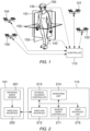
- the system comprises a sensor array comprising a plurality of sensors 201, a sensor array controller 110, a physical feedback mechanism 140 and a controller 110.
- Each sensor 201 is disposed on a respective one of a plurality of aerial vehicles 101, 102, 103, 104.
- the plurality of aerial vehicles 101, 102, 103, 104 can be arranged such that each sensor 201 is positioned so as to monitor a current position of a different part of the user's body 150.
- the controller 110 can determine a current position of the user's body 150, and control the physical feedback mechanism 140 to provide physical feedback to the user in dependence on the determined position of the user's body 150.
- each sensor 201 may determine three-dimensional coordinates of one or more points on the user's body 150 relative to the current location of the sensor 201, and wirelessly transmit the determined coordinates to the controller 110 via suitable wireless interfaces 202, 212.
- the system may also comprise a suitable display, such as virtual reality headset 130, for displaying a virtual reality, augmented reality or mixed reality image to the user.
- the plurality of sensors 201 may comprise a plurality of cameras arranged to capture images of the user's body.
- the controller 110 may apply a body recognition algorithm to one or more images captured by the plurality of cameras to determine the current position of the user's body 150.
- the plurality of cameras may be infrared depth cameras capable of determining a distance between the camera and the user's body 150.
- FIG. 2 is a block diagram illustrating functional elements of the controller 110 and an aerial vehicle 101 in the system of Fig. 1 .
- the controller 110 comprises a sensor array controller 211 configured to reposition the plurality of aerial vehicles 101, 102, 103, 104 so as to provide a line of sight between each one of the plurality of sensors 201 and a respective part of the user's body 150 monitored by said one of the plurality of sensors 201.
- the plurality of sensors can maintain their respective lines of sight, such that the controller 110 can accurately determine the current position of the user's body 150.
- the sensor controller 211 may reposition one or more of the plurality of aerial vehicles 101, 102, 103, 104 so that at least one of the sensors 201 has an unobstructed line of sight to the user's torso.
- the sensor array controller 211 may control the plurality of aerial vehicles 101, 102, 103, 104 so as to form an array of sensors 201 that surrounds the user 150. Such an array may be referred to as a circumambient array.
- the sensor array controller 211 may control the plurality of aerial vehicles 101, 102, 103, 104 so as to maintain a uniform spacing between adjacent ones of the aerial vehicles 101, 102, 103, 104, which may help to minimise the risk of collisions between aerial vehicles whilst also providing a clear view of the whole of the user's body 150.
- the sensor array controller 211 may control the plurality of aerial vehicles 101, 102, 103, 104 to maintain a fixed distance to the user 150.
- the sensor array controller 211 may control a circumambient array of the plurality of aerial vehicles 101, 102, 103, 104 to move in synchronicity with the user, by applying a similar rotation and forward movement to the circumambient array. Controlling the plurality of aerial vehicles 101, 102, 103, 104 in this way can allow the sensor array to maintain lines of sight to the different parts of the user's body 150.
- the plurality of sensors 201 may be attached to the aerial vehicles 101, 102, 103, 104 in a fixed manner. In other embodiments one or more of the plurality of sensors 201 are moveably mounted to the respective ones of the plurality of aerial vehicles 101, 102, 103, 104, such that the sensor 201 can be reoriented independently of the aerial vehicle 101, 102, 103, 104 to which it is mounted.
- the sensor array controller 211 can be configured to reorient one or more of the plurality of sensors 201 in addition to repositioning the plurality of aerial vehicles 101, 102, 103, 104, so as to provide the lines of sight between each one of the plurality of sensors 201 and a respective part of the user's body monitored by said one of the plurality of sensors 201.
- the sensor array controller 201 can choose from more options when determining how to reconfigure the sensor array to maintain optimum imaging conditions.
- the plurality of sensors may be configured to have variable focal lengths. This provides an additional degree of freedom to the sensor array controller 211, which can be configured to increase or decrease a focal length of one or more of the plurality of sensors 201 in addition to repositioning the plurality of aerial vehicles 101, 102, 103, 104, so as to provide a line of sight between each one of the plurality of sensors 201 and a respective part of the user's body monitored by said one of the plurality of sensors 201.
- one or more of the sensors 201 may comprise an imaging sensor with variable focal length which is moveably mounted to one of the aerial vehicles 101, 102, 103, 104, further increasing the degrees of freedom available to the sensor array controller 211 when determining how to reconfigure the sensor array.
- the sensor array comprises a head-mounted sensor worn on the user's head, such as a head-mounted camera
- the head-mounted sensor may also be configured to be capable of being reoriented and/or having a focal length adjusted by the sensor array controller 211.
- the sensor array controller 211 may be configured to reconfigure the sensor array so as to enable the current position of the user's body 150 to be determined with a desired degree of accuracy.
- the desired degree of accuracy may be defined in various ways, for instance in terms of the angular size of the user's body 150 within the field of view of the sensors 201, or in terms of a desired resolution of the user's body 150 in images captured by the sensors 201.
- the sensor array controller 211 may position one of the aerial vehicles 101, 102, 103, 104 so that the part of the user's body 150 that is currently being monitored by the sensor 201 on that aerial vehicle has at least a minimum angular size within the sensor's field of view.
- the sensor array controller 211 may reposition the aerial vehicle so as to increase the angular size of the part of the user's body 150 in the field of view of the sensor 201.
- the sensor array controller 211 may attempt to position the aerial vehicles 101, 102, 103, 104 in such a way that the user's body 150 occupies at least a minimum area within an image frame captured by each sensor 201.
- the minimum area may be a variable threshold that differs for different ones of the sensors 201, since the area of the image occupied by the user's body 150 will be different depending on the position of the sensor 201, for example whether the sensor 201 is positioned above, in front of, behind, or to the side of the user.
- the sensor array controller 211 may reconfigure the sensor array so as to attempt to maintain the desired degree of accuracy, for example by repositioning ones of the aerial vehicles 101, 102, 103, 104 and/or by changing the orientation and/or focal length of one or more of the sensors 201.
- the sensor array controller 211 may be configured to determine a number of the aerial vehicles 101, 102, 103, 104 that is required to determine the current position of the user's body with the desired degree of accuracy. Depending on the outcome of the determination, the required number of aerial vehicles may be equal to the number of aerial vehicles 101, 102, 103, 104 currently comprised in the sensor array, or may be greater than or lesser than the number of aerial vehicles 101, 102, 103, 104 currently comprised in the sensor array. In response to the determined number of aerial vehicles being less than the number of aerial vehicles currently comprised in the sensor array, the sensor array controller 211 may be configured to switch one or more redundant aerial vehicles into a standby mode in which said one or more redundant aerial vehicles do not form part of the sensor array.
- the term “redundant aerial vehicle” refers to an aerial vehicle that is deemed surplus to requirements by the sensor array controller 211, in that the desired degree of accuracy can be obtained without requiring the sensor(s) on the redundant aerial vehicle(s).
- An aerial vehicle that is switched into the standby mode may land and power down so as to conserve power.
- an aerial vehicle that is switched into the standby mode may automatically return to a charging station to begin charging an internal power source while in the standby mode.
- the sensor array controller 211 can be configured to switch one or more aerial vehicles from the standby mode into an active mode in which said one or more aerial vehicles now form part of the sensor array. In this way, standby aerial vehicles may be swapped in and out of the sensor array as and when they are required. This can help to reduce power consumption by avoiding a situation in which more aerial vehicles are currently in use than are needed to provide the controller 110 with the desired degree of accuracy, in terms of the data that is provided by the sensor array.
- the sensor array controller 211 may control the plurality of sensors 201 to monitor different parts of the user's body at different times. In this way, the parts of the user's body that are subject to monitoring by the plurality of sensors 201 can be changed by the sensor array controller 211 over time, for example depending on the mode of immersion (e.g. an autoscopic or a non-autoscopic mode of immersion) and the current point of view (POV) displayed to the user (e.g. whether a first-person POV or a third-person POV is used).
- the mode of immersion e.g. an autoscopic or a non-autoscopic mode of immersion
- POV current point of view
- the system when the system is operating in a first-person POV mode, the user's back will not be visible in the current field of view, and accordingly it may not be necessary for any of the plurality of sensors to maintain a line of sight to points on the user's back. This may still be true even when physical feedback is being applied to the part of the user's body 150 that is not currently visible to the user, for example their back.
- the plurality of sensors 201 may still be controlled to monitor one or more parts of the user's body 150 that are not currently visible to the user, for instance to enable more accurate motion tracking across the user's entire body, and/or to enable a calculation of a current or future point of contact between a virtual object and a part of the user's body that is not currently visible.
- information from the plurality of sensors 201 may enable the determination of a plurality of points of contact between virtual object(s) and parts of the user's body, including parts that may or may not be visible to the user.
- any part of the user's body 150 may be in, or to enter, the user's field of view at any point in time. It will be appreciated that depending on the scenario, for example depending on the size, shape and/or number of virtual objects currently in contact with the user's body 150, one part or a plurality of parts of the user's body 150 may be stimulated by the physical feedback mechanism 140, so as to provide either a single stimulus or a plurality of stimuli.
- the plurality of aerial vehicles 101, 102, 103, 104, 105 may be controlled to maintain lines of sight to all parts of the user's body 150 that are capable of being stimulated by the physical feedback mechanism 140, or to as much of the user's body 150 as is possible given the number of available sensors 201.
- the system may be configured to render the user's avatar in a transparent manner, such that parts of the avatar that would otherwise be occluded in an opaque rendering remain visible to the user at all times.
- the system may be configured to render the user's avatar in a transparent manner, such that parts of the avatar that would otherwise be occluded in an opaque rendering remain visible to the user at all times.
- extremities such as the hand or arm of the avatar may be occluded by the torso of the avatar.
- the transparency means that the hand/arm remains visible through the torso.
- an autoscopic mode of immersion can be provided by displaying the user's avatar as partially transparent, whilst applying a visual effect across a whole or part of the surface of the avatar that is synchronised with tactile stimulus.
- the visual and tactile feedback combine to create the illusion that the avatar is the user's own physical body as viewed from a third person POV and can therefore generate an autoscopic experience.
- a transparent rendering mode may be used when operating in a first-person viewpoint, for example by rendering virtual representations of any parts of the user's body that are currently within the user's first-person field of view (e.g. hands, arms, legs etc.) in a transparent manner.
- the plurality of aerial vehicles 101, 102, 103, 104, 105 may be controlled to maintain lines of sight to all parts of the user's body 150 that are capable of being stimulated by the physical feedback mechanism 140.
- the plurality of aerial vehicles 101, 102, 103, 104, 105 may be controlled to maintain lines of sight to parts of the user's body which are capable of being stimulated by the physical feedback mechanism and which are determined to be visible in the current field of view.
- the physical feedback mechanism 140 is embodied as a suit worn by the user 150.
- the term "suit” is used to refer to a wearable item that may be configured to cover a significant portion of the user's body 150, up to and including the entirety of the body 150.
- the suit 140 is configured to cover the torso, limbs and extremities, including the user's hands and feet.
- the physical feedback mechanism 140 can provide physical feedback across most or all of the user's body 150, providing a more immersive virtual or augmented reality experience.
- the physical feedback mechanism 140 may take a different form to that shown in Fig. 1 .
- the physical feedback mechanism 140 may comprise one or more physically separate modules each configured to be attached to a different part of the user's body 150, such as the torso, limbs, extremities, neck and/or head.
- the physical feedback mechanism 140 may only be configured to provide physical feedback to a limited part of the user's body, for example, in some embodiments the physical feedback mechanism 140 may consist of a glove or a pair of gloves configured to provide physical feedback only to the user's hands.
- the sensor array controller may control the plurality of aerial vehicles 101, 102, 103, 104, 105 to only maintain lines of sight to those parts of the user's body which are capable of being stimulated by the physical feedback mechanism, which in this example would be one or both hands.
- the physical feedback mechanism 140 may include a tactile feedback mechanism capable of providing tactile stimulus to one or more regions of the user's body 150.
- the tactile feedback mechanism may comprise a plurality of actuators capable of being controlled by the physical feedback controller 213 to deliver tactile stimulus to specific points or regions on the user's body 150.
- the plurality of actuators may be electrically activated, and accordingly the stimulus that is generated may be referred to as "electro-tactile" stimulation.
- the plurality of actuators may be distributed evenly across the surface of the user's body 150, or the distribution may vary across the body 150. For example, in some embodiments a higher number of actuators may be provided in one or more regions of the human body that are known to have a high density of touch receptors relative to other regions of the body.
- the physical feedback controller 213 may control the plurality of actuators to deliver dynamic tactile stimulation to the user's body 150.
- dynamic is used to denote tactile stimulation that is spatially and temporally differentiated, that is to say, that varies at different times and at different points in space.
- synchronous stimulation may be applied simultaneously at multiple locations on the user's body. The intensity of the tactile stimulation at any given point may be constant or may vary over time.
- the physical feedback mechanism 140 may include a kinaesthetic feedback mechanism capable of exerting a force on the body 150 so as to resist flexion and/or extension of the user's joints.
- a kinaesthetic feedback mechanism capable of exerting a force on the body 150 so as to resist flexion and/or extension of the user's joints.
- the term 'kinaesthetic' refers to a form of physical feedback that can be sensed by the user via proprioceptor organs that provide awareness of the position and movement of parts of the body.
- the kinaesthetic feedback mechanism may also be referred to as a proprioception feedback mechanism.
- the physical feedback mechanism 140 may comprise both a tactile feedback mechanism and a kinaesthetic feedback mechanism.
- the kinaesthetic feedback mechanism may be capable of forcibly moving parts of the user's body 150.
- the physical feedback controller 213 may control the kinaesthetic feedback mechanism so as to provide proprioceptive stimulus to the user, by applying external forces that affect the position and/or movement of the user's body 150. In this way, a more immersive user experience may be achieved by providing proprioceptive stimulus that complements and reinforces the stimuli received via the user's other senses, such as audio, visual and tactile stimulus.
- the physical feedback controller 213 can control the kinaesthetic feedback mechanism to resist movement of the user's body 150 through the boundary of a virtual object, providing a more immersive experience.
- a kinaesthetic feedback mechanism may comprise an exoskeleton comprising an assembly of struts connected by hinged joints.
- an exoskeleton may be embedded within a suit 140 worn by the user, such as the one illustrated in Fig. 1 , or may be worn externally to the suit 140.
- the exoskeleton may also comprise one or more actuators configured to apply a force to the struts on either side of a joint, so as to cause the joint to open or close.
- the actuators incorporated within the exoskeleton are hereinafter referred to as “joint actuators”
- tilt actuators incorporated within the tactile feedback mechanism
- suitable components for use as a joint actuator in a kinaesthetic feedback mechanism include, but are not limited to, motors, solenoids, artificial muscles such as electroactive polymers, and pneumatic or hydraulic cylinders.
- suitable components for use as tactile actuators in a tactile feedback mechanism include, but are not limited to, piezoelectric transducers and micromotors.
- the kinaesthetic feedback mechanism may be capable of operating in various modes, such as an inactive mode, a passive resistance mode, and an exertive mode.
- the physical feedback controller 213 does not control the joint actuators to exert any force, such that the user is able to freely move without encountering resistance.
- the joint actuators comprise electric motors
- the physical feedback controller 213 may disconnect all joint actuators from a power supply so that a spindle of each motor can freely rotate without exerting a resistive torque on the joint to which the motor is connected. In this way, the user is free to move whilst wearing the exoskeleton without being encumbered by resistance due to the presence of the joint actuators.
- the physical feedback controller 213 controls one or more joint actuators to exert a force in response to a user's movement causing a joint in the exoskeleton to flex or extend.
- the forces exerted by the joint actuators in the passive resistance mode act to resist the user's own movements.
- the force exerted by a joint actuator in the passive resistance mode may be in an opposite direction to the force exerted by the user, or may be in any other non-complimentary direction, that is, any direction that differs from the direction of the force exerted by the user.
- a joint actuator may be controlled to exert a braking force on a joint of the exoskeleton such that the exoskeleton resists the user's movements.
- the passive resistance mode may also be referred to as a 'subordinate' control mode, since the user perceives the movement of the exoskeleton to be subordinate to their own movements, albeit whilst applying some level of resistance.
- the physical feedback controller 213 controls one or more joint actuators to exert a sufficient force to cause a joint in the exoskeleton to flex or extend, overriding the user's own efforts to move the joint.
- a joint actuator may be configured to produce various types of movement of the adjoined limbs, including but not limited to abduction/adduction, pronation/supination, rotation and circumduction. The maximum force that can be exerted by a joint actuator may be limited, so as to avoid causing injury.
- the exertive mode may also be referred to as an 'insubordinate' control mode, since the user perceives the exoskeleton as behaving in a manner that is beyond their control, i.e. insubordinate to the user's own movements.
- the physical feedback controller 213 may switch between the inactive, passive resistance or exertive modes according to the current situation, for example, depending on whether the user is currently deemed to be in contact with a virtual object or any other virtual surface.
- the distinction between the passive resistance mode and the exertive mode depends upon the relationship between the forces exerted by the joint actuators and the forces exerted by the user.
- the user may perceive a transition from the exertive mode to the passive resistance mode, or vice versa, as a result of changing their own behaviour (e.g. their direction of movement and magnitude of forces exerted).
- the exoskeleton may be controlled in the exertive mode to repeatedly execute a dance movement, for instance as a training aid to help the user to learn a new dance routine.
- the user may reach a point at which their own movement trajectories become synchronised with the forced movements of the exoskeleton, and as such may perceive the exoskeleton's movements as changing from insubordinate to subordinate, even though the joint actuators may still be controlled in the same way as before.
- the physical feedback controller 213 may control a plurality of joint actuators at adjoining sections of the exoskeleton to exert a force on the respective joints, depending upon the magnitude of the counterforce deemed to be exerted by a virtual object.
- the joint actuator closest to the point of contact between the virtual object and the user's body 150 may be controlled to exert a corresponding counterforce on that joint.
- one or more joint actuators at adjoining sections of the exoskeleton can be controlled to exert forces on the respective joints between adjoining sections, so as to simulate the distributional effect of exerted counterforces upon distal segments of the user's body 150. In this way, the system can provide a more realistic simulation of the forces experienced when interacting with real physical objections, enabling a user to interact with virtual objects in a more convincing and immersive manner.
- the physical feedback controller 213 may control joint actuators at the wrist and/or finger joints to exert a counterforce to simulate the weight of the virtual object in the user's hand.
- the physical feedback controller 213 may control joint actuators in adjoining sections of the exoskeleton, such as the forearm, elbow, upper arm, shoulder, and so on, to simulate the effect of distributed counterforces exerted upon the user's body 150 as a result of lifting the virtual object.
- the physical feedback controller 213 may be capable of simultaneously providing feedback to simulate a plurality of separate events, such as a user picking up a virtual object with one hand whilst holding another virtual object in the other hand.
- the forces exerted on one arm by the exoskeleton may be independent of the forces exerted on the other arm by the exoskeleton, whilst the forces exerted on the torso may take into account the influence of both virtual objects.
- the physical feedback mechanism can be configured to exert a variable resistance to the user's movements in dependence on control signals received from the physical feedback controller 213, through other means than the joint actuators described above.
- the physical feedback mechanism in embodiments in which the physical feedback mechanism is embodied as an exoskeleton comprising a plurality of exoskeleton members, the plurality of exoskeleton members can include one or more adaptive members that are configured to have a controllable bending stiffness.
- an adaptive exoskeleton member can be rendered more or less flexible in dependence on control signals received from the physical feedback controller 213, such that the part of the exoskeleton frame in which the adaptive member presents a lesser or greater resistance to the user's own body movements.
- an adaptive exoskeleton member may comprise a material such as an electroactive polymer.
- the physical feedback controller 213 may continuously recalculate the forces exerted on the user's body by a virtual object as a user interacts with the object, and adjust the forces exerted by the joint actuators accordingly. For example, if a user pushes against a virtual object and then breaks contact with the object, the forces involved may change significantly over time.
- the physical feedback controller 213 may control a kinaesthetic feedback mechanism and a tactile feedback mechanism to provide both tactile stimulus and proprioceptive stimulus, thereby providing a more realistic simulation.
- Tactile stimulus refers to stimulus that can be detected by touch receptors within the user's body
- proprioceptive also referred to as kinaesthetic
- Tactile stimulus and proprioceptive stimulus are both examples of different types of physical feedback.
- the system may further comprise a user arousal sensor for monitoring the user's current level of alertness, which in psychology is referred to as arousal.
- the controller may be configured to adapt an intensity level of the proprioceptive and/or tactile stimulus according to the user's current level of arousal, as determined by the user arousal sensor.
- the sensor, controller and physical feedback mechanism together form a biofeedback loop which can autonomously regulate the amount of proprioceptive and/or tactile feedback provided to the user.
- the tactile feedback mechanism may be capable of generating proprioceptive stimulus, instead of or in addition to the proprioceptive stimulus generated by a kinaesthetic feedback mechanism.
- tactile actuators in a tactile feedback mechanism may be controlled to generate mild levels of kinaesthetic resistance/holding, and joint actuators in a kinaesthetic feedback mechanism may be controlled to generate stronger levels of kinaesthetic resistance and/or the forced repositioning of the user's body 150.
- the forced feedback mechanism may additionally comprise one or more joint position sensors configured to detect a current position of the struts on either side of the joint.
- the controller 110 may receive information from each joint position sensor that is indicative of the current positions of the struts on either side of the joint, so as to enable the controller 110 to determine a current position of the exoskeleton, and by implication the current position of the user's body 150.
- Such information can indicate the current angle of some or all joints in the user's body 150, but does not convey information about the position and shape of the surface of the user's body 150 between the joints.
- the information obtained from the joint position sensor may be referred to as “low-resolution position information”
- the information obtained from the plurality of sensors 201 mounted on the aerial vehicles 101, 102, 103, 104 may be referred to as “high-resolution position information”.
- the controller 110 may be configured to take into account both the low-resolution position information from the joint sensors and the high-resolution position information from the aerial vehicle sensors when determining the current position of the user's body, to improve the accuracy.
- the aerial vehicles 101, 102, 103, 104 may not be permitted to enter the user's peripersonal space, so as to avoid the risk of a vehicle colliding with the user. Due to this restriction on movement of the aerial vehicles 101, 102, 103, 104, a situation may still arise in which part of the user's body remains obscured to all of the sensors in the sensor array. In such a situation, the part of the user's body that is obscured to all of the sensors may be referred to as an "occluded part" or an "occluded surface".
- the controller 110 may augment the high-resolution position information from the sensor array with low-resolution position information for the part of the user's body that is currently not visible to the sensor array, to provide more complete information about the user's current position.
- the low-resolution position information may capture information that is not included in the high-resolution position information, and vice versa.
- the aerial vehicle sensors may be capable of capturing fine detail such as muscular movement and the bending of limbs/tissue between joints of the exoskeleton, which cannot be determined from the exoskeleton sensor information alone (i.e. the low-resolution position information).
- the joint sensors in the exoskeleton may be capable of measuring a force exerted by the user, which cannot be determined directly from the aerial vehicle sensor data (i.e. the high-resolution position information).
- the physical feedback mechanism may comprise one or more pressure sensors disposed so as to measure a pressure exerted by the user at locations between joints. Such pressure sensors can provide additional information in relation to the force that the user is applying to the virtual object, and can allow the direction and/or magnitude of any forces exerted by the user to be determined with greater accuracy.
- the physical feedback may be synchronised with a virtual reality, augmented reality or mixed reality image that is displayed to the user, to provide a more convincing and more immersive user experience.
- the system may comprise a display device such as a headset 130 for displaying virtual reality, augmented reality or mixed reality images to the user.
- the system comprises a display in the form of a headset 130.
- the controller 110 comprises a rendering unit 214 which can render a virtual reality, augmented reality or mixed reality image and send the rendered image to the display 130 for presentation to the user.
- the headset 130 may comprise a sensor for detecting a current orientation of the user's head, for example a gyroscope and/or electronic compass, which can transmit information about the user's physical angle of view to the controller 110. This information can be utilised by the rendering unit 214 when rendering the virtual reality, augmented reality or mixed reality image.
- the rendering unit 214 may render the image from a first-person perspective or a third-person perspective.
- the first-person perspective may also be referred to as an egocentric perspective
- the third-person perspective may also be referred to as an allocentric perspective.
- a rendered virtual-reality image may include a virtual representation of a part of the user's body that is within the user's current field of view, as determined based on the current position of the user's body 150 and the direction in which the user is looking.
- the controller 110 can use the array of sensors 201 to accurately determine the current position of the user's body 150.
- the accuracy of the determination may be further improved by also taking into account information about the angles of joints in an exoskeleton worn by the user, based on information received from one or more joint position sensors, and/or by taking into account information about the current angle of the user's head, based on information received from a gyroscope or other suitable sensor in a headset 130 worn by the user.
- the system can accurately determine the current position of the user's body 150 and therefore render a virtual representation of part of the user's body 150 that is currently in view which more closely matches the user's own proprioceptive perception of their body position, thereby providing a more convincing and immersive experience.
- the headset may comprise an image sensor arranged so as to capture images with a similar field of view to the user's current view.
- the image sensor may, for example, be an infrared depth camera or sensor.
- the image sensor may be positioned in or on the headset in a fixed manner, such that the camera points in a fixed direction relative to the headset.
- the headset may further comprise a camera positioning mechanism for automatically repositioning the camera according to a user's eye movements, so that the camera points in a direction of the user's gaze.
- an eye tracking sensor may be used to determine the current gaze direction of the user, and the camera positioning mechanism can be automatically controlled to reposition the headset-mounted camera to point in the same direction as the user's gaze.
- one of the plurality of aerial vehicles may be positioned such that the sensor mounted on the aerial vehicle is anterior to, and directed towards, a point in space which is the current focus of the user's attention.
- This is the focus point that is conferred by binocular vision, which is hereinafter referred to as the 'gaze point'.
- the gaze point may alternatively be referred to as the 'point of regard', since this is the point that is currently the focus of the user's attention, or may be referred to as the 'stereoscopic focal point'.
- data provided by the sensor can be used to accurately determine the current position of parts of the body that are within the user's current field of view.
- the aerial vehicle may be positioned such that the sensor mounted on the aerial vehicle has a line of sight which is inverse to the user's current line of sight, that is to say, such that the sensor is directed along the user's line of sight in the opposite direction to that of the user's gaze.
- an image captured by the sensor in effect corresponds to the inverse of the user's current field of view.
- another one of the plurality of aerial vehicles may be positioned in such a way as to image the obscured body part.
- the position of the obscured body part may be determined based on low-resolution position information as described above, for example using data received from one or more joint sensors in an exoskeleton worn by the user.
- the system may further comprise an eye tracking sensor configured to track the user's eye movements and determine the current direction of the user's gaze. The gaze point can then be determined based on the current direction of the user's gaze.
- an eye tracking sensor may be omitted, and the gaze point may simply be assumed to be a point at a certain distance from the user along the mid-sagittal plane of the user's head.
- the eye tracking sensor may, for example, be mounted on the headset. Alternatively, the eye tracking sensor may be mounted elsewhere.
- the headset may comprise transparent eyepieces onto which an augmented reality image may be projected, in a similar manner to a heads-up display.
- the user's eyes may still be visible from an external perspective even when the user is wearing the headset, and as such the eye tracking sensor may be disposed on one of the aerial vehicles.
- an eye tracking sensor may comprise an image sensor disposed so as to capture an image of the user's eye, and an image processing algorithm may be configured to process the captured image to determine the current direction of the user's gaze.
- Real-time tracking of the user's body position via the sensors mounted on the aerial vehicles may therefore be complemented by information gathered using other sensors, such as an eye tracking sensor, headset-mounted orientation sensor and/or headset-mounted image sensor, further increasing the accuracy with which the user's current body position and gaze direction can be determined.
- sensors such as an eye tracking sensor, headset-mounted orientation sensor and/or headset-mounted image sensor, further increasing the accuracy with which the user's current body position and gaze direction can be determined.
- the controller may control one of the plurality of aerial vehicles to adopt a position that is anterior to, and directed towards, the gaze point, to ensure accurate tracking of body parts that are currently within the user's field of view.
- the aerial vehicle that is directed towards the gaze point may be designated as a 'master', and other ones of the aerial vehicles may be designated as ⁇ slaves', with the positions of the slave aerial vehicles being set relative to the current location of the master aerial vehicle.
- the system may comprise a headset-mounted camera and a camera positioning mechanism as described above.
- a headset-mounted sensor when the system is operating in a first-person mode the headset-mounted sensor may be designated as the 'master', and the plurality of aerial vehicles may each be designated as ⁇ slaves'.
- the positions of the slave aerial vehicles are set relative to the current location and orientation of the headset-mounted sensor.
- the aerial vehicle that is positioned to have a sensor line of sight that is inverse to that of the user is considered to be a slave, since the headset-mounted sensor acts as the master. In this way, the headset-mounted camera and the aerial vehicle can both be automatically repositioned in response to the user's eye movements as detected by the eye tracking sensor.
- the gaze point may deviate significantly from the mid-sagittal plane of the user's head, for example when the user adjusts their gaze far to the left or far to the right by eye movement alone, without commensurate head movement.
- a more accurate determination of the current gaze point can be obtained by taking into account information from an eye tracking sensor.
- the controller may reposition the master aerial vehicle if the location of the gaze point deviates from the previous location of the gaze point by more than a certain amount. In more detail, if the controller determines that the gaze point has moved away from the previous gaze point by more than a threshold distance, the controller may control the master aerial vehicle that was directed towards the previous gaze point to move to a suitable new position according to the current gaze point. In this way, accurate tracking of body parts within the user's field of view can be maintained. The controller may also control the slave aerial vehicles to reposition themselves relative to the master aerial vehicle when the master is moved to a new position.
- the rendering unit 214 may render an image of a 3D avatar (a virtual representation of a figure corresponding to a user's body) which corresponds to the determined current position of the user's body 150.
- the avatar may be rendered in a semi-transparent manner to allow the user to view objects on the opposite side of the avatar to the current viewpoint.
- the system can be used to induce an autoscopic experience in which the user perceives the environment from a perspective outside of their own body.
- autoscopic experience the user perceives their body to be somewhere other than its actual location, and accordingly such types of autoscopic experience may be referred to as an 'out-of-body' experience.
- the user's sense of bodily unity is disrupted, such that they perceive themselves to be in a different location to their physical body.
- the term 'autoscopy' may refer to the perception of any form of bodily relocation/projection with or without the preservation of bodily unity.
- Embodiments of the present invention may be configured to produce an autoscopic experience by providing a combination of visual and tactile feedback which is spatially and temporally isomorphic.
- An autoscopic experience may be generated in a first-person mode or in a third-person mode by appropriate control of the physical feedback, in synchronisation with a visual rendering of part of the user's body displayed on the headset.
- the system can accurately determine the current position of the user's body 150 and therefore produce a more immersive autoscopic experience, by rendering an image of an avatar that more closely corresponds to the user's current body position and orientation.
- the system may be configured to be operable in a third-person autoscopic mode in which the user's avatar is displayed as partially transparent.
- a visual effect that is spatially and temporally varying can be applied across a surface of the avatar, for example as a visually discernible alternation of colour and/or brightness.
- the visual effect may be globally distributed across the surface of the avatar, giving a spatially varying 'shimmering' appearance.
- the tactile feedback mechanism can be used to provide the user with tactile stimulus which is spatially and temporally isomorphic to the visual effect applied to the avatar.
- the visual and tactile stimulus can be synchronised with each other.
- an autoscopic experience can be generated. Furthermore, by applying a visual effect across the surface of the avatar together with synchronised tactile stimulus across the user's body, an autoscopic experience can be generated and sustained irrespective of whether the user is making contact with any parts of the virtual environment or with any virtual objects within the environment, and irrespective of whether the user is currently mobile or stationary.
- the array of aerial vehicles can be controlled to maintain a distal (i.e. whole-body) view of the user, for example from a posterior profile such that the user views their avatar from behind.
- the spatial position of the autoscopic visual effect and synchronised tactile stimulus can be continually updated so as to match the user's movements, further reinforcing the belief that the third-person avatar being observed is the user's own body.
- a similar approach may be used to generate an autoscopic experience while the system is operating in a first-person autoscopic mode. Even though a first-person mode is used, the user may still be able to observe virtual representations of parts of their own body, for example by tilting their head downwards or raising their hands in front of their face. In such situations, parts of the user's body within their current field of view can be rendered in a semi-transparent manner similar to the third-person avatar described above, with a similar visual effect and synchronised tactile stimulus being applied to the corresponding part of the user's body via the tactile feedback mechanism.
- the system may be configured to operate in a so-called telepresent mode.
- the system may be switchable between autoscopic and telepresent modes.
- the telepresent mode is similar to a conventional virtual reality mode, insofar as the virtual representation of parts of the user's body that are currently within the field of view match the size, shape and position of the user's actual corresponding body parts.
- parts of the avatar that are within the current field of view may be rendered opaquely, so as to block the user's view of objects or other body parts occluded by part of the avatar.
- Physical feedback such as proprioceptive and/or tactile stimulus, can be provided commensurately with points of contact between the user's body and virtual objects, providing an immersive virtual experience.
- the system may be configured to display a sectional intersection of the user's third-person avatar within a first-person perspective.
- part of the third-person avatar can be displayed as if the user was viewing the avatar from a different position within the body, as opposed to viewing the avatar from a viewpoint outside of the body as in a conventional third-person mode.
- the user can therefore perceive the third-person avatar as a prolongation of their own body as perceived from a first-person point of view, and accordingly this type of operating mode will hereinafter be referred to as a 'prolongated perspectivisation' mode.
- the controller may determine the user's current viewpoint based on information received from a headset-mounted orientation sensor such as a gyroscope, whilst a sectional intersection of the third-person avatar can be rendered and displayed by the controller based on information received from the sensors mounted on the array of aerial vehicles.
- two distinct arrays of aerial vehicles and sensors may be used to capture information for use by the controller in rendering the sectional view of the third-person avatar.
- a first sensor array can be used to capture real-time kinematics for use in rendering the sectional representation of the third-person avatar, by positioning a first master aerial vehicle using coordinates obtained from a positioning sensor (e.g. GPS receiver) worn on the user's body.
- a second sensor array can be used to capture information for determining the current field of view from a first-person perspective, including the position of any parts of the user's body within the current field of view, by positioning a second master aerial vehicle at the current gaze point, as described above.
- the sectional view of the third-person avatar can be changed by moving the aerial vehicles of the first sensor array.
- the aerial vehicles in the first sensor array can be moved closer to or further from the user, to zoom or crop the area of the user's body that is rendered as a sectional view of the third-person avatar.
- autoscopic profiles may be set for a plurality of users in which parameters such as: the distance between the aerial vehicles in the first sensor array and the user, and thus the displayed avatar area; the distance of superimposition upon/from the user's first-person vantage point; and the intersection depth with regard to the plane of presentation, are customised for each user so as to establish optimal autoscopic profiles on an individual user basis.
- autoscopic profiles is not restricted to the prolongated perspectivisation mode.
- user-specific autoscopic profiles can be created, stored and updated for other types of operating modes.
- parameters which can be stored in an autoscopic profile include, but are not limited to, the frequency and/or amplitude of concurrent visual and tactile feedback for producing an autoscopic effect, and/or an optimal spatial-temporal pattern of concurrent visual and tactile feedback for the current user.
- parameters which can be stored in an autoscopic profile include, but are not limited to, the frequency and/or amplitude of concurrent visual and tactile feedback for producing an autoscopic effect, and/or an optimal spatial-temporal pattern of concurrent visual and tactile feedback for the current user.
- intermittently increasing the rhythm of stimulation applied to a user can generate a more intense autoscopic experience.
- the depth of autoscopisis experienced by the user may be improved, and the time taken to initiate the autoscopic experience, referred to as the onset latency, may be decreased.
- Figure 4 illustrates a flowchart showing a method of rendering a third person representation of the user from a user-selected viewpoint, according to an embodiment of the present invention.
- the third-person representation may be referred to as the user's avatar.
- the method shown in Fig. 4 may be used when rendering the avatar in a third-person autoscopic mode as described above, or may be used in a 'normal' (i.e. non-autoscopic) third-person mode.
- step S401 the system receives user input indicative of a desired viewpoint of the third-person perspective view, via the user interface.
- the user interface allows the user to select different viewpoints, for example by selecting one of a plurality of discrete predefined viewpoints or by moving a virtual camera to an arbitrary position relative to the avatar.
- step S402 the sensor array controller controls one of the plurality of aerial vehicles to adopt a position corresponding to the user's desired viewpoint.
- the aerial vehicle positioned at the desired viewpoint can capture information about the user's current body position from the same position relative to the user's body as the current viewpoint relative to the avatar, and so a more accurate avatar can be generated and displayed.
- the sensor array controller may also control other ones of the aerial vehicles to reposition themselves relative to the sensor at the user's current viewpoint.
- the sensor array controller may also control other ones of the aerial vehicles to reposition themselves relative to the sensor at the user's current viewpoint.
- an array of sensors mounted on four aerial vehicles may be controlled to capture data from four vantage points concurrently.
- the user interface may be configured to allow the user to select one of a plurality of third-person viewpoints corresponding to the current locations of the individual aerial vehicles in the sensor array.
- the third-person profile by which the avatar is subsequently displayed may correspond to any one of the four aerial vehicle vantage points.
- the aerial vehicles may, for example, be controlled to maintain fixed positions across the frontal and sagittal planes as the user moves.
- the sensor array controller may control the aerial vehicle array to maintain an equidistant configuration, meaning that all of the aerial vehicles are positioned at the same distance from the user's body.
- the sensor array controller may then control the aerial vehicle sensor array to rotate about the user in three dimensions in accordance with movement of a virtual camera about the third-person avatar, including pitch, roll and yaw rotations.
- These sensor array reconfigurations, such as rotations can be automatically performed as pre-programmed routines of context dependent cues/events, or can be selected by the user from a menu of pre-programmed routines, or can be performed under full manual user control, allowing arbitrary reconfiguration of the sensor array.
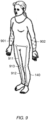
- FIG. 5 illustrates a positioning unit for determining coordinates of a point on a user's body
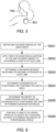
- FIG. 6 is a flowchart showing a method of controlling the plurality of aerial vehicles to avoid contact with the user's body.
- a positioning unit is included in the upper midpoint at the rear of the suit (i.e. between the lower portion of the shoulders). In other embodiments the positioning unit could be located elsewhere on the user's body. In some embodiments the positioning unit may be configured to be detached and reattached at different locations on the user's body, for example according to whether the system is operating with the sensor array in a first-person configuration or in a third-person configuration. Furthermore, in some embodiments a plurality of positioning units may be disposed at different locations on the user's body.
- the positioning unit may be a global navigation satellite system (GNSS) receiver, such as a Global Positioning System (GPS) receiver.
- GNSS global navigation satellite system
- GPS Global Positioning System
- the sensor array controller is configured to control each one of the plurality of aerial vehicles to maintain a set position in three-dimensional space relative to the determined coordinates.
- GNSS positioning unit permits the master aerial vehicle to assume any position relative to the determined GNSS coordinates, irrespective of whether a line of sight between the positioning unit and the master aerial vehicle becomes occluded by part of the user's body or any other object.
- any slave aerial vehicles included in the sensor array may be controlled to adopt equidistant positions relative to the determined GNSS coordinates.
- the method shown in Fig. 6 can allow the sensor array controller to ensure that the aerial vehicles maintain a safe separation distance to the user, to reduce the risk of collisions between the user and the aerial vehicles.
- the controller 110 obtains one or more images of the users' body from the sensors.
- the controller 110 applies a body recognition algorithm to the obtained images to determine the lengths of the user's limbs, and in step S603 the controller 110 uses this information to calculate the maximum distance that each limb can reach from the location of the positioning unit 501.
- the sensor array controller 211 obtains the current coordinates (e.g. GPS coordinates) of the positioning unit 501.
- step S605 the sensor array controller 211 determines the extent of the user's peripersonal space, meaning the space within which the user can interact physically with their environment, based on the known location of the positioning unit and the maximum distances that can be reached by the user's limbs. Finally, in step S604 the sensor array controller 211 controls the plurality of aerial vehicles to adopt positions that are at least the determined minimum distance away from the positioning unit.
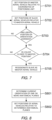
- a flowchart is illustrated showing a method of designating each of the plurality of aerial vehicles as a master or a slave, according to an embodiment of the present invention.
- the plurality of aerial vehicles in the sensor array may be organised into a master aerial vehicle and one or more slave aerial vehicles.
- the method shown in Fig. 7 can be used to automatically reassign the 'master' role according to the user's movements.
- step S701 the sensor array controller 211 is configured to set the position for the master aerial vehicle relative to the determined coordinates of the positioning unit 501. Then, in step S702 the sensor array controller 211 sets a respective position for each of the one or more slave aerial vehicles relative to the position of the master aerial vehicle. The sensor array controller 211 may then monitor the user's movements in step S703 to check whether the user's position or orientation has changed since the master and slave positions were assigned.
- step S704 the sensor array controller 211 checks whether one of the slave vehicles is now closer to the set position for the master than the actual master vehicle. If it is determined that one of the slave vehicles is now closer to the set position for the master, then in step S705 the sensor array controller 211 designates that slave vehicle as a new master, and designates the old master as a slave. This approach avoids having to relocate the master and slave vehicles due to sudden large movements made by the user.
- the sensor array controller 211 may take other factors into account instead of, or in addition to, the distances between the slave and master vehicles and the new position that has been set for the master vehicle. For example, in some embodiments in step S704 the sensor array controller 211 is configured to determine whether a predicted time for the current master aerial vehicle to move from its current location to the set position for the master aerial vehicle will exceed a time limit. It will be appreciated that the predicted time will depend in part on the distance between the current location of the master vehicle and the new position that has been set for the master vehicle, but will also depend on other factors, such as the current speed and direction of travel of the master aerial vehicle (i.e. the current velocity of the master aerial vehicle), the maximum speed at which the master aerial vehicle can travel, and a path that the master aerial vehicle must take to reach the new set position, which may depend on whether any obstacles are present between the current location of the master aerial vehicle and the new set position.
- the current speed and direction of travel of the master aerial vehicle i.e. the current velocity of the master aerial vehicle
- the time limit may be a fixed (i.e. predefined) time limit, or may be a variable time limit.
- the time limit may be a variable time limit that is set by the sensor array controller 211 depending on the user's current speed of movement, such that a shorter time limit is set when the user is moving more quickly.
- the time limit may be a variable time limit that is set by the sensor array controller 211 depending on the shortest time that would be taken for one of the slave aerial vehicles to reach the new set position for the master aerial vehicle.
- the sensor array controller 211 may keep the existing master/slave designations, and may control the master aerial vehicle to move from its current location to the set position for the master aerial vehicle. On the other hand, in response to a determination that the predicted time exceeds the time limit, the sensor array controller 211 may proceed to step S705 and designate one of the slave aerial vehicles as the master aerial vehicle, by designating the slave aerial vehicle that is predicted to be able to reach the new set master position in the shortest time amongst all of the aerial vehicles.
- the sensor array controller 211 may also choose to reorient and/or change the focal length of one or more of the sensors in steps S701 and S702.
- the sensor array comprises a head-mounted sensor configured to be worn on the user's head, such as an imaging sensor arranged so as to capture an image indicative of the user's current field of view
- the sensor array controller 211 may choose to change an orientation and/or adjust a focal length of the head-mounted sensor. Such reorientation and/or focal length adjustment may take place instead of, or as well as, setting new positions of the aerial vehicles in steps S701 and S702.
- FIG. 8 a flowchart is illustrated showing a method of setting the positions of the plurality of aerial vehicles relative to anatomical planes of the user's body, according to an embodiment of the present invention.
- the sensor array controller 211 determines a current orientation in space of one or more anatomical planes of the user's body, such as the frontal plane, sagittal plane, and transverse plane.
- the sensor array controller 211 may identify the anatomical planes based on information obtained using the plurality of sensors, for example by analysing images captured using infra-red depth cameras mounted on the aerial vehicles.
- the sensor array controller 211 may determine the current orientation in space of said one or more anatomical planes based on the determined coordinates of the positioning unit.
- the sensor array controller 211 may take into account both the coordinates of the positioning unit and information from the plurality of sensors to more accurately determine the current orientation of the anatomical planes.
- step S802 the sensor array controller 211 controls each one of the plurality of aerial vehicles to maintain a set position relative to the one or more anatomical planes.
- the sensor array controller 211 can ensure that the sensors maintain a full field of view around the user's entire body.
- the sensor array controller 211 may control the first and second aerial vehicles to adopt positions on opposite sides of the user's body along an intersection between the transverse plane and the sagittal plane, and control the third and fourth aerial vehicles to adopt positions on opposite sides of the user's body, along an intersection between the transverse plane and the frontal plane.
- This arrangement ensures that the aerial vehicles are disposed at uniform angular intervals around the user, allowing a more complete three-dimensional model of the user's current body position to be generated.
- the system may comprise a second sensor array comprising a plurality of sensors mounted on a second plurality of aerial vehicles.
- the second sensor array can be used to map the surrounding physical setting and/or scan the environment for physical objects that could pose a collision risk, whilst the first plurality of aerial vehicles continually monitors the user's movements.
- the second plurality of aerial vehicles may be controlled to scan the environment in more detail in the user's current direction of travel for obstacles that may present a collision hazard to the user, and/or to the aerial vehicles themselves. If any such obstacles are detected by the second sensor array, the system may issue warnings to the user which indicate the direction and distance of obstacles, and which indicate the limits of virtual space and vantage points.
- warnings may be provided to the user in the form of visual cues located in the periphery of the virtual reality display.
- Providing a collision avoidance system which can help the user to avoid obstacles in this way can allow the system to be deployed in more types of environment.
- the system may comprise suitable apparatus capable of permitting unrestricted locomotion, for example in the form of an omnidirectional treadmill.
- the velocity and/or acceleration of the user's locomotive movement may be measured by suitable sensors included in the omnidirectional treadmill. The measured velocity and/or acceleration can be transmitted to the controller 110 and processed in parallel with data from the sensor array, allowing the avatar to be plotted as moving within a virtual setting in accordance with the user's own physical movements.
- Embodiments of the invention have been described in which a user may interact with virtual objects, and be provided with physical feedback in the form of proprioceptive feedback and/or tactile stimulus at the corresponding part of the user's body, so as to provide a more immersive and convincing virtual experience.
- Interactions between the user and virtual objects may be categorised as 'user-solicited contact' or 'unsolicited contact', depending on whether the user has intentionally contacted the virtual object.
- the controller 110 may be configured to automatically determine whether contact between the user and any given virtual object was user-solicited or unsolicited.
- the controller 110 may take into account various factors, including but not limited to: the proximity of the contacted body part to the object immediately before contact; the trajectory of the body part immediately before contact; the current direction in which the user is looking, based on eye-tracking information; whether the user reacts to the object; whether the user draws back from the object (i.e. moves away from the object after contact); the length of time for which the object is the focal point of the user's gaze, as being indicative of the level of fixation/inspection upon the object; and whether the object was within the periphery or outside of the user's field of view before, during and after contact.
- the user's viewpoint may be reoriented accordingly. For example, when a new user-solicited contact is detected while the system is operating in the first-person mode, the user's viewpoint may be reoriented by zooming in on the object with which the user is interacting, thereby affording a clearer view of the object. As a further example, when a new user-solicited contact is detected while the system is operating in the third-person mode, one or more of the camera position, direction and zoom level may be adjusted to provide the user with a clearer view of the object than was afforded by the previous viewpoint.
- a user's viewpoint is automatically reoriented without changing the display mode (i.e. first-person or third-person).
- an automatic reorientation of the viewpoint in response to user-solicited contact with an object can include a transition from first-person to third-person perspectives, or vice versa. For example, if the system is operating in a third-person display mode and user-solicited contact with an object is detected, for instance when a user's gaze is directed at a virtual object within reach of the user and/or the user picks up the virtual object, the display mode may switch to a first-person perspective to afford a closer view of the object.
- the display mode may return to the third-person perspective.
- the opposite transition may occur, by automatically reorienting the viewpoint from first-person perspective to third-person perspective when user-solicited contact is detected.
- the viewpoint may be automatically reoriented only when user-solicited contact is detected.
- automatic reorientation in the case of unsolicited contact which would otherwise be disruptive to the user's current virtual embeddedness/engagement, can be avoided.
- the system can determine that the contact with the other object is unsolicited and therefore avoid a potentially disruptive additional reorientation due to the unsolicited contact.
- the contact with the other object which can be referred to as an 'unsolicited object'
- the system may determine that the contact is not user-solicited and can avoid automatically reorienting the viewpoint towards the contacted object.
- a contact event between part of the user's body and a virtual object may initially be unsolicited but may develop into user-solicited contact.
- a user may unintentionally come into contact with a virtual object, but may then turn their attention to the object and begin engaging with it.
- automatic reorientation may not occur immediately upon the unsolicited contact but may be delayed for a certain time while the system waits to see if the user engages with the object. If the user is deemed to be insufficiently reciprocating to the unsolicited object's contact, reorientation does not ensue. Conversely, when the user is deemed to be sufficiently reciprocating to an unsolicited object's contact, automatic reorientation may ensue.
- a user may override the automatic reorientation function to prevent the viewpoint being automatically reoriented. For example, if a 'non-solicited object override' setting is selected, automatic reorientation may not ensue as a result of contact occurring with a non-solicited object.
- the reorientation compliments the user's active engagement and/or inspection of the soliciting object, thereby providing a more intuitive user experience and making it easier for users to interact with virtual objects. Conversely, by preventing automatic reorientation when the user is deemed to be insufficiently engaging with an unsolicited object, an otherwise disruptive automatic reorientation can be avoided.
- tactile feedback commensurate with the newly-solicited contact can also be provided simultaneously with the pre-existing contact-independent isomorphic visual-tactile feedback.
- Embodiments of the invention have been described in which an array of sensors mounted on a plurality of aerial vehicles adopt positions around a user to track the user's position and movements.
- the system may also comprise a second array of sensors mounted on a second plurality of aerial vehicles, which may be referred to as a 'standby array'.
- a standby array of aerial-vehicle-mounted sensors can be repositioned in advance of a contact event when it is predicted that current trajectories of the user and/or an object are due to intersect at a future point in time.
- the system may predict a time and location of contact between the user and the object as a function of the relative velocities of the user and the object and their respective positions.
- the time and location at which the contact is predicted to occur may be determined based on eye tracking received from an eye tracking sensor, and/or based on body position information determined using data captured by the vehicle-mounted sensor array.
- the aerial vehicles of the standby array can be controlled to adopt suitable positions relative to the predicted location of contact with the object, before the predicted time at which the contact will occur. Then, when contact occurs between the user and the object and the viewpoint is automatically reoriented as described above, the system can begin using the standby array to continue monitoring the user's position while operating in the reoriented viewpoint.
- the first sensor array may adopt positions suitable for first-person operation, such as by positioning the sensors to track points on the front of the user's body without necessarily tracking points on the back of the user's body.
- the standby array may be controlled to adopt suitable positions for third-person operation in advance of the contact occurring. Then, when contact does occur, if the contact is deemed to be user-solicited and automatic reorientation ensues, the sensors of the second array are already in suitable positions to accurately track the user and enable third-person rendering from the reoriented viewpoint.
- the standby array can be positioned in advance without knowing whether the contact will be solicited or unsolicited. If the ensuing contact is deemed to be unsolicited, then automatic reorientation may not occur, and the standby array may no longer be required. For example, the aerial vehicles of the standby array may return to resting positions if not currently required.
- the physical feedback mechanism 140 of Fig. 1 is illustrated in further detail, according to an embodiment of the present invention.
- the physical feedback mechanism 140 of the present embodiment is in the form of an exoskeleton, as has been described above, comprising a plurality of exoskeleton members 911, 912 connected by one or more moveable joints 913.
- exoskeleton members 911, 912 and joints 913 are simplified in Fig. 9 , and only the lower part of the exoskeleton is illustrated. It will be appreciated that the exoskeleton may extend across a greater or lesser extent of the user's body than that illustrated in Fig. 9 , depending on the requirements of a particular embodiment.
- the physical feedback mechanism 140 of the present embodiment comprises a plurality of location sensors 901, 902 distributed over at least part of the user's body.
- the location sensors are configured to provide information on a current location of a respective surface of the user's body, in other words, a surface on which the location sensor 901, 902 is disposed.
- the controller 110 is configured to determine the current position of the user's body based on the information obtained using the plurality of aerial vehicle sensors and based on the information provided by the plurality of location sensors 901, 902. Examples of suitable location sensors include, but are not limited to, orientation sensors such as gyroscopes and/or movement sensors such as accelerometers, which may also be referred to as inertial sensors.
- the controller 110 can use information obtained from the location sensors 901, 902 to track changes in the locations of the respective sensors over time.
- the information that can be obtained from the location sensors 901, 902 can complement the information obtained from the plurality of aerial vehicle sensors, and together both sets of information can be used to determine the current position of the user's body with a greater degree of accuracy. For example, depending on the current position of the user's body and a current spatial arrangement of the plurality of aerial vehicle sensors, one part of the user's body may be visible to one or more of the aerial vehicle sensors whilst another part of the user's body may be hidden from view of all of the aerial vehicle sensors. For example, if the user is crouching or has their arms held close to their body, it may not be possible to position the aerial vehicles so as to provide complete visibility of the user's entire body.
- a surface on the user's body that is currently hidden from view of the plurality of aerial vehicle sensors can be referred to as an "occluded surface", and a surface on the user's body that is currently visible to one or more of the plurality of aerial vehicle sensors can be referred to as a "visible" surface.
- the location sensors 901, 902 are distributed across a substantial portion of the user's body so as to increase the likelihood that for a given body position and configuration of aerial vehicles 101, 102, 103, 104 that results in there being one or more occluded surfaces, there will be at least one location sensor 901, 902 on the occluded surface(s). In this way, even though an occluded surface may not currently be visible to the aerial vehicle sensors, the controller 110 is still able to determine the current position of the user's body by determining the current position of the occluded surface based on information obtained from any of the location sensors that are disposed on the occluded surface.
- the controller 110 may also take into account information from any joint sensors on an occluded surface. At the same time, the controller 110 can continue to determine the current position of any visible surfaces based on the information obtained using the plurality of sensors, and also takes into account information from location sensors 901, 902 on visible surfaces to increase the accuracy of the determination.
- the plurality of location sensors 901, 902 includes location sensors disposed on opposing surfaces of one or more parts of the user's body. In general, any two surfaces on the user's body that face in opposite directions can be considered to be "opposing" surfaces in this context. Examples of pairs of opposing surfaces of the user's body include, but are not limited to, the anterior and posterior sides of the torso, the palm and the back of the hand, the calf and the shin, and so on. For example, in the embodiment illustrated in Fig. 9 a plurality of first location sensors 901 are disposed on the anterior surfaces of both forearms, whilst a plurality of second location sensors 902 are disposed on the posterior surfaces of both forearms. Although in Fig. 9 a plurality of first location sensors 901 are disposed on the anterior surfaces of both forearms, whilst a plurality of second location sensors 902 are disposed on the posterior surfaces of both forearms.
- location sensors 901, 902 are only illustrated on the forearms for clarity, it will be appreciated that the use of location sensors is not limited to these locations. In other embodiments the location sensors may be disposed on any other parts of the user's body as required, instead of or in addition to the forearms.
- Disposing location sensors 901, 902 on opposing surfaces of the user's body in this way can increase the likelihood that for a given body position and configuration of aerial vehicles 101, 102, 103, 104 that results in there being one or more occluded surfaces, there will be at least one location sensor 901, 902 on the occluded surface(s).
- the forearm location sensors 901, 902 in Fig. 9 as an example, when the use holds their arms by their sides with palms facing inwards, the anterior surfaces of the forearms may not be visible to any of the aerial vehicle sensors, since the anterior surfaces of the forearms are facing inwards towards the sides of the torso. In such a scenario, the anterior surfaces of the forearms may constitute occluded surfaces, and the controller 110 may determine the current position of the anterior surfaces of the forearms based on the information provided by the first location sensors 901.
- opposite surfaces should not be construed as implying that the location sensors on any given body part, such as the head, torso, a limb or an extremity, are only disposed on two opposite sides of that part of the body, although this may be one possible arrangement. More detailed location information can be obtained from the location sensors by disposing the location sensors 901, 902 at numerous points around the circumference of a certain body part, such that the current position of the entire surface of the body part can be determined by the controller 110 with a high degree of accuracy. This may be referred to as "encasement”, in that the location sensors 901, 902 may be considered to effectively surround and therefore encase the body part in a location sensor array.
- exoskeleton members 911, 912 may be disposed so as to act on opposing surfaces of a part of the user's body.
- one or more actuators associated with a moveable joint 913 of the exoskeleton assembly can be used to exert a force on the body part in opposite directions (i.e. 'pushing' vs. 'pulling') via the respective exoskeleton members 911, 912 disposed on opposing surfaces of the body part.
- controlling an actuator to exert a force on the user's lower leg via an exoskeleton member 912 disposed on the shin can encourage the user to bend their leg at the knee
- controlling an actuator to exert a force on the user's lower leg via an exoskeleton member 912 disposed on the calf i.e. an opposing surface to the shin
- controlling an actuator to exert a force on the user's lower leg via an exoskeleton member 912 disposed on the calf i.e. an opposing surface to the shin
- more than two exoskeleton members may be disposed around the circumference of the respective part of the user's body so as to increase the degrees of freedom available to the physical feedback mechanism.
- the physical feedback mechanism 140 comprises both a plurality of location sensors 901, 902 and an exoskeleton 911, 912, 913
- a physical feedback mechanism such as an exoskeleton 911, 912, 913 may not comprise any such location sensors 901, 902.
- a plurality of location sensors 901, 902 may be used in combination with a different form of physical feedback mechanism other than an exoskeleton.
- the system may be used in a therapeutic context, such as during muscular/physical rehabilitation or the treatment of psychological conditions.
- the system may be calibrated to capture and present visual information to persons with varying kinds of neuropsychological neglect (e.g., hemispatial) and visual impairments, or as a multisensory substitution and/or assistive communication device.
- the system may be used to assist mobility. For instance, in cases where the user is a subject suffering from restricted mobility, such as a person with multiple sclerosis or a physical injury, the physical feedback mechanism can be controlled to assist the user in performing movements that they would not be capable of executing independently.
- tactile feedback may be used to somatically manage high levels of anxiety and to promote sensorimotor integration in persons with autism.
- the provision of stimulation using static and portable deep pressure devices in persons with autism has been reported to reduce state levels of anxiety and increase sensorimotor integration, whilst vibrohaptic stimulation has also been shown to promote social abilities in persons with autism.
- the system may be used in educational, training and occupational contexts.
- the system may be used to train a user in various types of manual tasks, including but not limited to industrial, medical and engineering fields.
- the system may be used to permit user exploration of remotely rendered environments, such as inaccessible or hostile environments.
- the system can comprise a communication system for remotely controlling a robotic device in dependence on the user's body movements, to enable tasks to be carried out remotely.
- the system may be used within leisure and entertainment contexts. For example, immersive/interactive cinema, gaming, and remote travel scenarios.
Landscapes
- Engineering & Computer Science (AREA)
- Theoretical Computer Science (AREA)
- Physics & Mathematics (AREA)
- General Physics & Mathematics (AREA)
- General Engineering & Computer Science (AREA)
- Human Computer Interaction (AREA)
- Multimedia (AREA)
- Remote Sensing (AREA)
- Astronomy & Astrophysics (AREA)
- Health & Medical Sciences (AREA)
- Computer Vision & Pattern Recognition (AREA)
- General Health & Medical Sciences (AREA)
- Psychiatry (AREA)
- Social Psychology (AREA)
- Aviation & Aerospace Engineering (AREA)
- Radar, Positioning & Navigation (AREA)
- Automation & Control Theory (AREA)
- User Interface Of Digital Computer (AREA)
Claims (21)
- System, umfassend:eine Sensoranordnung, die eine Vielzahl von Sensoren (201) umfasst, die jeweils so angeordnet sind, dass sie eine aktuelle Position eines oder mehrerer Körperteile des Benutzers (150) überwachen;eine Vielzahl von Fluggeräten (101, 102, 103, 104), wobei jedes der Vielzahl von Luftfahrzeugen einen entsprechenden Sensor aus der Vielzahl von Sensoren darauf aufweist;eine Sensoranordnungssteuerung (211), die so konfiguriert ist, dass sie die Vielzahl von Fluggeräten neu positioniert, um eine Sichtlinie zwischen jedem der Vielzahl von Sensoren, die auf einem der Vielzahl von Fluggeräten angeordnet sind, und einem entsprechenden Teil des Körpers des Benutzers bereitzustellen, der von dem einen der Vielzahl von Sensoren überwacht wird;einen Mechanismus mit physikalischem Feedback (140) zum Bereitstellen von physikalischem Feedback für den Benutzer, wobei der Mechanismus mit physikalischem Feedback so konfiguriert ist, dass er am Körper des Benutzers getragen wird;eine Vielzahl von Positionssensoren (901, 902), die über mindestens einen Teil des Körpers des Benutzers verteilt sind, wobei jeder der Positionssensoren so konfiguriert ist, dass er Informationen über eine aktuelle Position einer entsprechenden Oberfläche des Körpers des Benutzers bereitstellt; undeine Steuerung (213), die so konfiguriert ist, dass sie eine aktuelle Position des Körpers des Benutzers basierend auf Informationen bestimmt, die unter Verwendung der Vielzahl von Sensoren und der von der Vielzahl von Standortsensoren bereitgestellten Informationen erhalten werden, und dass sie den Mechanismus mit physikalischem Feedback steuert, um dem Benutzer in Abhängigkeit von der bestimmten Position des Körpers des Benutzers ein physikalisches Feedback zu geben,wobei der Körper des Benutzers sichtbare Oberflächen und verdeckte Oberflächen umfassen kann, abhängig von der aktuellen Position des Körpers des Benutzers und einer aktuellen räumlichen Anordnung der Vielzahl von Sensoren, die auf der Vielzahl von Fluggeräten angeordnet sind, wobei die sichtbaren Oberflächen Körperteile des Benutzers umfassen, die für einen oder mehrere der Vielzahl von Sensoren sichtbar sind, und die verdeckten Oberflächen Körperteile des Benutzers umfassen, die für die Vielzahl von Sensoren nicht sichtbar sind,wobei die Vielzahl von Positionssensoren auf mindestens zwei gegenüberliegenden Flächen des einen oder der mehreren Körperteile des Benutzers angeordnet sind, so dass, wenn eine oder mehrere der gegenüberliegenden Flächen eine verdeckte Fläche ist, die Steuerung so konfiguriert ist, dass sie die aktuelle Position des Körperteils des Benutzers basierend auf den von den Positionssensoren gelieferten Informationen bestimmt und die aktuelle Position aller sichtbaren Flächen basierend auf den Informationen bestimmt, die unter Verwendung der Vielzahl von auf der Vielzahl von Fluggeräten angeordneten Sensoren erhalten wurden.
- System nach Anspruch 1, umfassend:eine Rendering-Einheit (214), die so konfiguriert ist, dass sie in Abhängigkeit von der bestimmten aktuellen Position des Körpers des Benutzers ein Bild rendert, das eine virtuelle Darstellung zumindest eines Körperteils des Benutzers beinhaltet; undeine Anzeigeeinheit (150), die so konfiguriert ist, dass sie dem Benutzer das gerenderte Bild anzeigt.
- System nach Anspruch 2, wobei die Rendering-Einheit so konfiguriert ist, dass sie eine perspektivische Ansicht des Körpers des Benutzers in der dritten Person von einem Standpunkt eines der Vielzahl von Sensoren aus darstellt,wobei das System eine Benutzerschnittstelle (215) umfasst, die so konfiguriert ist, dass sie Eingaben des Benutzers empfängt, die einen gewünschten Standpunkt der perspektivischen Ansicht in der dritten Person angeben, und die Steuerung der Sensoranordnung so konfiguriert ist, dass sie eines der Vielzahl von Fluggeräten so steuert, dass es eine Position einnimmt, die dem durch die Benutzereingabe angegebenen gewünschten Standpunkt entspricht, oderwobei das System gegebenenfalls eine Benutzerschnittstelle umfasst, die so konfiguriert ist, dass sie einen Benutzerbefehl zum Umschalten von einem Erste-Person-Betrachtungsmodus in einen Dritte-Person-Betrachtungsmodus empfängt, wobei die Rendering-Einheit als Reaktion auf den Benutzerbefehl so konfiguriert ist, dass sie die perspektivische Dritte-Person-Ansicht des Körpers des Benutzers aus dem Standpunkt eines der Vielzahl von Sensoren rendert.
- System nach einem der vorhergehenden Ansprüche, wobei die Steuerung so konfiguriert ist, dass sie die aktuelle Position einer oder mehrerer sichtbarer Oberflächen basierend auf den Informationen bestimmt, die unter Verwendung der Vielzahl von Sensoren erhalten wurden, und basierend auf Informationen, die von mindestens einem der Vielzahl von Positionssensoren erhalten wurden, die auf der einen oder den mehreren sichtbaren Oberflächen angeordnet sind,
wobei die Vielzahl der Positionssensoren gegebenenfalls einen oder mehrere Orientierungssensoren und/oder einen oder mehrere Bewegungssensoren umfasst, sodass die von dem einen oder den mehreren Orientierungssensoren und/oder dem einen oder den mehreren Bewegungssensoren erhaltenen Informationen verwendet werden können, um Veränderungen einer Position der jeweiligen Sensoren im Laufe der Zeit nachzuverfolgen. - System nach Anspruch 1, wobei der Mechanismus mit physikalischem Feedback Folgendes umfasst:einen Mechanismus mit taktilem Feedback, der so konfiguriert ist, dass er taktile Reize für mindestens ein Körperteil des Benutzers bereitstellt,wobei der Mechanismus mit taktilem Feedback eine Vielzahl von Aktuatoren umfasst, die so gesteuert werden können, dass sie eine variable Kraft auf eine Oberfläche des Körpers ausüben,wobei die Vielzahl der Aktuatoren in einer Region des Körpers mit einer höheren Dichte an Berührungsrezeptoren enger beieinander liegen und in einer Region des Körpers mit einer geringeren Dichte an Berührungsrezeptoren weniger eng beieinander liegen.
- System nach einem der vorhergehenden Ansprüche, wobei der Mechanismus mit physikalischem Feedback einen Mechanismus mit kinästhetischem Feedback umfasst, der so konfiguriert ist, dass er kinästhetische Reize für mindestens ein Körperteil des Benutzers bereitstellt, wobei der Mechanismus mit kinästhetischem Feedback eine Exoskelettanordnung umfasst, die so konfiguriert ist, dass sie ganz oder teilweise am Körper des Benutzers getragen wird, wobei die Exoskelettanordnung Folgendes umfasst:eine Vielzahl von Exoskelett-Elementen (911, 912), die durch ein oder mehrere bewegliche Gelenke (913) verbunden sind, undeinen oder mehrere Aktuatoren, die jedem beweglichen Gelenk der Exoskelettanordnung zugeordnet sind, wobei jeder Aktuator von der Steuerung gesteuert werden kann, um den kinästhetischen Reiz bereitzustellen, indem eine Kraft auf die jeweiligen Elemente der Vielzahl von Exoskelett-Elementen ausgeübt wird, die mit dem beweglichen Gelenk verbunden sind,wobei das System einen oder mehrere Gelenksensoren umfasst, die jeweils so konfiguriert sind, dass sie eine Position eines entsprechenden einen des einen oder der mehreren beweglichen Gelenke erkennen, und die Steuerung so konfiguriert ist, dass sie die aktuelle Position des Körpers des Benutzers basierend auf Informationen bestimmt, die von dem einen oder den mehreren Gelenksensoren erkannt wurden, und basierend auf den Informationen, die von der Vielzahl von Sensoren erhalten wurden, die auf der Vielzahl von Fluggeräten angeordnet sind,wobei einer oder mehrere der Positionssensoren zwischen den Gelenken des Körpers des Benutzers angeordnet sind,wobei der Mechanismus mit physikalischem Feedback so konfiguriert ist, dass er in Abhängigkeit von Steuersignalen, die von der Steuerung empfangen werden, einen variablen Widerstand auf die Bewegungen des Benutzers ausübt, und die Vielzahl der Exoskelett-Elemente ein oder mehrere adaptive Elemente umfasst, die so konfiguriert sind, dass sie eine steuerbare Biegesteifigkeit aufweisen und/oder zwei oder mehr Exoskelett-Elemente beinhalten, die auf gegenüberliegenden Oberflächen eines oder mehrerer Körperteile des Benutzers angeordnet sind.
- System nach einem der vorhergehenden Ansprüche, umfassend:eine am Körper des Benutzers angeordnete Positionierungseinheit (501), wobei die Positionierungseinheit so konfiguriert ist, dass sie die Koordinaten einer aktuellen Position der Positionierungseinheit im dreidimensionalen Raum bestimmt,wobei die Steuerung der Sensoranordnung so konfiguriert ist, dass sie jedes der Vielzahl von Fluggeräten so steuert, dass es eine bestimmte Position im dreidimensionalen Raum relativ zu den bestimmten Koordinaten aufrechterhält.
- System nach Anspruch 7, wobei die Steuerung der Sensoranordnung so konfiguriert ist, dass sie die Vielzahl von Fluggeräten so steuert, dass sie Positionen einnehmen, die mindestens einen minimalen Abstand zu den bestimmten Koordinaten der Positionierungseinheit haben,wobei die Steuerung der Sensoranordnung so konfiguriert ist, dass sie den minimalen Abstand in Abhängigkeit von einer bekannten Position der Positionierungseinheit am Körper des Benutzers und von einem maximalen Abstand von dem bekannten Standort bestimmt, der durch maximale Ausdehnung eines oder mehrerer Gliedmaßen des Körpers des Benutzers erreicht werden kann,wobei die Steuerung der Sensoranordnung gegebenenfalls so konfiguriert ist, dass sie basierend auf Informationen, die unter Verwendung der Vielzahl von Sensoren erhalten wurden, eine Länge jedes der genannten einen oder mehreren Gliedmaßen bestimmt und den maximalen Abstand in Abhängigkeit von der bestimmten Länge der einen oder mehreren Gliedmaßen bestimmt.
- System nach Anspruch 7 oder 8, wobei die Vielzahl der Fluggeräte ein Hauptfluggerät und ein oder mehrere Nebenfluggeräte umfasst,wobei die Steuerung der Sensoranordnung so konfiguriert ist, dass sie für jedes des einen oder der mehreren Nebenfluggeräte eine entsprechende Position in Relation zu der Position des Hauptluftfahrzeugs einstellt,wobei die Steuerung der Sensoranordnung gegebenenfalls so konfiguriert ist, dass sie die Position für das Hauptfluggerät relativ zu den bestimmten Koordinaten der Positionierungseinheit einstellt.
- System nach Anspruch 9, wobei die Steuerung so konfiguriert ist, dass sie einen aktuellen Blickpunkt des Benutzers bestimmt, und die Steuerung der Sensoranordnung so konfiguriert ist, dass sie das Hauptfluggerät so positioniert, dass einer der Vielzahl von Sensoren, die auf dem Hauptfluggerät angeordnet sind, auf den bestimmten Blickpunkt gelenkt wird.
- System nach Anspruch 10, umfassend:einen Augenverfolgungssensor, der so konfiguriert ist, dass er eine aktuelle Blickrichtung des Benutzers erkennt,wobei die Steuerung so konfiguriert ist, dass sie basierend auf den vom Augenverfolgungssensor empfangenen Informationen den aktuellen Blickpunkt bestimmt und das Hauptfluggerät in Abhängigkeit von einer Bestimmung, dass sich der aktuelle Blickpunkt von einem zuvor bestimmten Blickpunkt unterscheidet, neu positioniert.
- System nach einem der Ansprüche 9 bis 11, wobei verschiedene der Vielzahl von Fluggeräten als Hauptfluggerät bezeichnet werden können, und
wobei die Steuerung der Sensoranordnung so konfiguriert ist, dass sie in Reaktion auf eine Veränderung der Koordinaten der Positionierungseinheit und/oder eine Ausrichtung des Körpers des Benutzers eines des einen oder der mehreren Nebenfluggeräte als Hauptfluggerät bestimmt. - System nach Anspruch 12, wobei die Steuerung so konfiguriert ist, dass sie bestimmt, ob eine vorhergesagte Zeit für die Bewegung des Hauptluftfahrzeugs von seiner aktuellen Position zu der für das Hauptfluggerät eingestellten Position ein Zeitlimit überschreitet, und dass sie das Hauptfluggerät steuert, damit es sich von seinem aktuellen Standort zu der für das Hauptfluggerät eingestellten Position bewegt, und zwar in Reaktion auf eine Bestimmung, dass die vorhergesagte Zeit das Zeitlimit nicht überschreitet, oder dass sie das eine der Nebenfluggeräte als das Hauptfluggerät bestimmt, und zwar in Abhängigkeit von einer Bestimmung, dass die vorhergesagte Zeit das Zeitlimit überschreitet.
- System nach Anspruch 13, wobei das Zeitlimit in Abhängigkeit von der aktuellen Bewegungsgeschwindigkeit des Benutzers eingestellt wird, so dass ein kürzeres Zeitlimit eingestellt wird, wenn sich der Benutzer schneller bewegt.
- System nach einem der vorhergehenden Ansprüche, wobei die Vielzahl der Sensoren beweglich angebracht ist, so dass jeder Sensor unabhängig neu ausgerichtet werden kann,
wobei die Steuerung der Sensoranordnung so konfiguriert ist, dass sie einen oder mehrere der Vielzahl von Sensoren zusätzlich zur Neupositionierung der Vielzahl von Fluggeräten neu ausrichtet, um eine Sichtlinie zwischen jedem der Vielzahl von Sensoren und einem jeweiligen Körperteil des Benutzers bereitzustellen, der von dem einen der Vielzahl von Sensoren überwacht wird. - System nach einem der vorhergehenden Ansprüche, wobei die Vielzahl von Sensoren einen am Kopf befestigten Sensor umfasst, der so konfiguriert ist, dass er am Kopf des Benutzers getragen werden kann,wobei die Steuerung der Sensoranordnung so konfiguriert ist, dass sie den am Kopf befestigten Sensor neu ausrichtet,wobei der am Kopf befestigte Sensor ein Bildsensor ist, der so angeordnet ist, dass er ein Bild erfasst, das das aktuelle Sichtfeld des Benutzers anzeigt.
- System nach einem der vorhergehenden Ansprüche, wobei die Vielzahl der Sensoren so konfiguriert ist, dass sie variable Brennweiten aufweisen,
wobei die Steuerung der Sensoranordnung so konfiguriert ist, dass sie die Brennweite eines oder mehrerer der Vielzahl von Sensoren zusätzlich zur Neupositionierung der Vielzahl von Fluggeräten vergrößert oder verkleinert, um eine Sichtlinie zwischen jedem der Vielzahl von Sensoren und einem entsprechenden Körperteil des Benutzers bereitzustellen, der von dem einen der Vielzahl von Sensoren überwacht wird. - System nach einem der vorhergehenden Ansprüche, wobei die Steuerung der Sensoranordnung so konfiguriert ist, dass sie die Anzahl der Fluggeräte bestimmt, die erforderlich sind, um die aktuelle Position des Körpers des Benutzers mit einem gewünschten Genauigkeitsgrad zu bestimmen,wobei als Reaktion darauf, dass die bestimmte Anzahl von Fluggeräten geringer ist als eine Anzahl von Fluggeräten, die gegenwärtig in der Sensoranordnung umfasst sind, die Steuerung der Sensoranordnung so konfiguriert ist, dass sie ein oder mehrere redundante Fluggeräte in einen Standby-Modus umschaltet, in dem das eine oder die mehreren redundanten Fluggeräte keinen Teil der Sensoranordnung bilden, undwobei als Reaktion auf die bestimmte Anzahl von Fluggeräten, die größer ist als die Anzahl von Fluggeräten, die derzeit in der Sensoranordnung umfasst sind, die Steuerung der Sensoranordnung so konfiguriert ist, dass sie ein oder mehrere Fluggeräte aus dem Standby-Modus in einen aktiven Modus umschaltet, in dem das eine oder die mehreren Fluggeräte einen Teil der Sensoranordnung bilden,wobei die Steuerung der Sensoranordnung gegebenenfalls so konfiguriert ist, dass sie bei der Bestimmung der Anzahl der benötigten Fluggeräte eine aktuelle Körperposition des Benutzers berücksichtigt.
- System nach einem der vorhergehenden Ansprüche, wobei die Steuerung der Anordnung von Sensoren so konfiguriert ist, dass sie basierend auf Informationen, die unter Verwendung der Vielzahl von Sensoren erhalten wurden, eine aktuelle Orientierung im Raum einer oder mehrerer anatomischer Ebenen des Körpers des Benutzers bestimmt, und ferner so konfiguriert ist, dass sie jedes der Vielzahl von Fluggeräten so steuert, dass es eine festgelegte Position relativ zu der einen oder den mehreren anatomischen Ebenen aufrechterhält.
- System nach Anspruch 19, wenn es von Anspruch 7 abhängt, wobei die Steuerung der Sensoranordnung so konfiguriert ist, dass sie basierend auf den bestimmten Koordinaten der Positionierungseinheit die aktuelle Orientierung im Raum der einen oder mehreren anatomischen Ebenen bestimmt,
wobei die eine oder mehreren anatomischen Ebenen gegebenenfalls eine Frontalebene und/oder eine Sagittalebene und/oder eine Querebene beinhalten, die Vielzahl von Fluggeräten erste, zweite, dritte und vierte Fluggeräte umfasst, die Sensoranordnungssteuerung so konfiguriert ist, dass sie die ersten und zweiten Fluggeräte so kontrolliert, dass sie Positionen auf gegenüberliegenden Seiten des Körpers des Benutzers entlang eines Schnittpunkts zwischen der Querebene und der Sagittalebene einnehmen, und die Steuerung der Sensoranordnung ist so konfiguriert, dass sie die dritten und vierten Fluggeräte so steuert, dass sie Positionen auf gegenüberliegenden Seiten des Benutzerkörpers entlang eines Schnittpunkts zwischen der Querebene und der Frontalebene einnehmen. - System nach einem der vorhergehenden Ansprüche, wobei die Vielzahl der Sensoren eine Vielzahl von Kameras umfasst, die so angeordnet sind, dass sie Bilder des Körpers des Benutzers aufnehmen,
wobei die Steuerung so konfiguriert ist, dass sie einen Körpererkennungsalgorithmus auf ein oder mehrere Bilder anwendet, die von der Vielzahl von Kameras aufgenommen wurden, um zu bestimmen, ob ein Objekt Teil des Körpers des Benutzers ist.
Applications Claiming Priority (2)
| Application Number | Priority Date | Filing Date | Title |
|---|---|---|---|
| GBGB1906420.3A GB201906420D0 (en) | 2019-05-07 | 2019-05-07 | Virtual augmented and mixed reality systems with physical feedback |
| PCT/GB2020/051112 WO2020225556A1 (en) | 2019-05-07 | 2020-05-06 | Virtual, augmented and mixed reality systems with physical feedback |
Publications (3)
| Publication Number | Publication Date |
|---|---|
| EP3966664A1 EP3966664A1 (de) | 2022-03-16 |
| EP3966664B1 true EP3966664B1 (de) | 2024-03-27 |
| EP3966664C0 EP3966664C0 (de) | 2024-03-27 |
Family
ID=67226284
Family Applications (1)
| Application Number | Title | Priority Date | Filing Date |
|---|---|---|---|
| EP20725732.0A Active EP3966664B1 (de) | 2019-05-07 | 2020-05-06 | Systeme mit virtueller, erweiterter und gemischter realität mit physikalischem feedback |
Country Status (4)
| Country | Link |
|---|---|
| US (2) | US11989351B2 (de) |
| EP (1) | EP3966664B1 (de) |
| GB (1) | GB201906420D0 (de) |
| WO (1) | WO2020225556A1 (de) |
Families Citing this family (5)
| Publication number | Priority date | Publication date | Assignee | Title |
|---|---|---|---|---|
| US11790669B2 (en) * | 2020-04-27 | 2023-10-17 | Nvidia Corporation | Systems and methods for performing operations in a vehicle using gaze detection |
| EP4254124B1 (de) * | 2022-03-29 | 2024-11-27 | Isaac Alfred Stern | Betrieb einer innerhalb einer arena navigierenden drohne |
| CN117085301B (zh) * | 2023-10-20 | 2024-02-13 | 中国科学院自动化研究所 | 基于虚拟现实的康复机器人多反馈康复训练方法及系统 |
| CN119232973B (zh) * | 2024-09-09 | 2025-09-16 | 南京卓翼智航科技有限公司 | 一种基于无人机视频的虚拟现实融合方法 |
| AU2025204327B1 (en) * | 2025-06-11 | 2026-03-26 | Jouf University | Integrated drone-based motion capture and smart insole system for real-time biomechanical analysis in outdoor environments |
Family Cites Families (89)
| Publication number | Priority date | Publication date | Assignee | Title |
|---|---|---|---|---|
| US5771181A (en) | 1994-12-14 | 1998-06-23 | Moore; Robert S. | Generation for virtual reality simulator systems |
| ES2214115B1 (es) | 2002-10-15 | 2005-07-16 | Universidad De Malaga | Sistema de reconocimiento automatico de objetos por proyeccion en una base algebraica y controlado remotamente por realidad virtual. |
| AU2002368501A1 (en) | 2002-12-31 | 2004-07-22 | Massimo Bergamasco | Ekoskeleton interface apparatus |
| US7098776B2 (en) * | 2003-04-16 | 2006-08-29 | Massachusetts Institute Of Technology | Methods and apparatus for vibrotactile communication |
| NL1030440C2 (nl) | 2005-11-16 | 2007-05-21 | Univ Twente | Bewegingsvolgsysteem. |
| US8543217B2 (en) * | 2006-02-24 | 2013-09-24 | Medtronic, Inc. | Stimulation templates for configuring stimulation therapy |
| EP1970005B1 (de) | 2007-03-15 | 2012-10-03 | Xsens Holding B.V. | System und Verfahren zur Bewegungsnachverfolgung über eine Kalibriereinheit |
| US20110046915A1 (en) | 2007-05-15 | 2011-02-24 | Xsens Holding B.V. | Use of positioning aiding system for inertial motion capture |
| US8203487B2 (en) | 2009-08-03 | 2012-06-19 | Xsens Holding, B.V. | Tightly coupled UWB/IMU pose estimation system and method |
| EP2180920A1 (de) | 2007-07-20 | 2010-05-05 | Össur HF | Prothese bzw. orthopädische vorrichtung mit rückmeldung |
| US20090240170A1 (en) * | 2008-03-20 | 2009-09-24 | Wright State University | Systems and methods for determining pre-fall conditions based on the angular orientation of a patient |
| WO2010045271A1 (en) * | 2008-10-14 | 2010-04-22 | Joshua Victor Aller | Target and method of detecting, identifying, and determining 3-d pose of the target |
| CN101819462B (zh) | 2010-03-12 | 2011-07-20 | 东南大学 | 基于力/触觉交互设备的图像纹理的力触觉再现系统 |
| US9892546B2 (en) * | 2010-06-30 | 2018-02-13 | Primal Space Systems, Inc. | Pursuit path camera model method and system |
| US20120025945A1 (en) | 2010-07-27 | 2012-02-02 | Cyberglove Systems, Llc | Motion capture data glove |
| CN202771366U (zh) | 2011-12-19 | 2013-03-06 | 苏茂 | 外构架式双向力反馈数据手套 |
| CN102717383B (zh) | 2012-06-29 | 2014-08-20 | 北京航空航天大学 | 一种新型的六自由度力反馈装置 |
| KR101389894B1 (ko) | 2012-07-18 | 2014-04-29 | 주식회사 도담시스템스 | 모션 캡쳐 기술을 이용한 가상 현실 시뮬레이션 장치 및 방법 |
| US11311209B1 (en) * | 2013-01-19 | 2022-04-26 | Bertec Corporation | Force measurement system and a motion base used therein |
| DK3014394T3 (da) * | 2013-07-05 | 2022-07-11 | Jacob A Rubin | Helkrops-menneske-computer-grænseflade |
| EA032658B1 (ru) | 2013-07-15 | 2019-06-28 | Вр Электроникс Лимитид | Способ интерактивной физиологической синхронизации пользователя с виртуальной средой |
| US9658454B2 (en) | 2013-09-06 | 2017-05-23 | Omnivision Technologies, Inc. | Eyewear display system providing vision enhancement |
| US10415975B2 (en) | 2014-01-09 | 2019-09-17 | Xsens Holding B.V. | Motion tracking with reduced on-body sensors set |
| JP2015153387A (ja) | 2014-02-19 | 2015-08-24 | 日本電気株式会社 | 仮想現実体感装置、仮想現実体感方法、及びプログラム |
| US9754167B1 (en) | 2014-04-17 | 2017-09-05 | Leap Motion, Inc. | Safety for wearable virtual reality devices via object detection and tracking |
| US10406059B2 (en) * | 2014-04-21 | 2019-09-10 | The Trustees Of Columbia University In The City Of New York | Human movement research, therapeutic, and diagnostic devices, methods, and systems |
| US10423227B2 (en) * | 2014-07-21 | 2019-09-24 | Dexta Robotics | Hand exoskeleton force feedback system |
| EP3218736B1 (de) * | 2014-11-10 | 2023-06-07 | Valve Corporation | Positionsverfolgungssysteme und -verfahren |
| CN105892626A (zh) | 2014-12-15 | 2016-08-24 | 普瑞深视科技(北京)有限公司 | 用于虚拟现实环境中的下肢运动仿真控制设备 |
| MX2015001947A (es) | 2015-02-13 | 2016-08-12 | Secretaría De Educación Pública - Tecnológico Nac De México | Robot exoesqueleto de mano enfocado a rehabilitacion motriz superior. |
| US11461936B2 (en) * | 2015-03-17 | 2022-10-04 | Raytrx, Llc | Wearable image manipulation and control system with micro-displays and augmentation of vision and sensing in augmented reality glasses |
| RU2015115262A (ru) | 2015-04-23 | 2016-11-10 | Константин Геннадьевич Чанчиков | Устройство для компенсации перемещения человека при его наземных локомоциях |
| US20170108929A1 (en) * | 2015-04-28 | 2017-04-20 | Morgan Walker Sinko | System and Method for Full Motion Capture and Haptic Feedback Suite |
| US9836117B2 (en) * | 2015-05-28 | 2017-12-05 | Microsoft Technology Licensing, Llc | Autonomous drones for tactile feedback in immersive virtual reality |
| US9665170B1 (en) | 2015-06-10 | 2017-05-30 | Visionary Vr, Inc. | System and method for presenting virtual reality content to a user based on body posture |
| CN204840790U (zh) | 2015-06-16 | 2015-12-09 | 杭州颐客科技有限公司 | 虚拟现实人体全向移动输入平台无行动限制人体约束机构 |
| US10694155B2 (en) * | 2015-06-25 | 2020-06-23 | Intel Corporation | Personal sensory drones |
| WO2017024177A1 (en) | 2015-08-04 | 2017-02-09 | Board Of Regents Of The Nevada System Of Higher Education,On Behalf Of The University Of Nevada,Reno | Immersive virtual reality locomotion using head-mounted motion sensors |
| GB201514721D0 (en) | 2015-08-19 | 2015-09-30 | Morgan Innovation & Technology Ltd | Haptic stimulation apparatus |
| CN105117022A (zh) * | 2015-09-24 | 2015-12-02 | 北京零零无限科技有限公司 | 一种控制无人机随脸转动的方法和装置 |
| CN105222761A (zh) | 2015-10-29 | 2016-01-06 | 哈尔滨工业大学 | 借助虚拟现实及双目视觉技术实现的第一人称沉浸式无人机驾驶系统及驾驶方法 |
| US10890964B2 (en) | 2016-01-07 | 2021-01-12 | Harshit SHRIVASTAVA | Intent based inputs and forced feedback system for a virtual reality system |
| US20170220110A1 (en) | 2016-02-03 | 2017-08-03 | Peter Stanley Hollander | Wearable Locomotion Capture Device |
| CN109477966B (zh) | 2016-02-18 | 2022-06-03 | 苹果公司 | 具有内-外位置跟踪、用户身体跟踪和环境跟踪的用于虚拟现实和混合现实的头戴式显示器 |
| US10943036B2 (en) * | 2016-03-08 | 2021-03-09 | Az, Llc | Virtualization, visualization and autonomous design and development of objects |
| KR20170114458A (ko) | 2016-04-05 | 2017-10-16 | 조건희 | 스테레오 카메라를 장착하여 가상현실 3d 영상으로 주변을 탐색하는 드론 및 이와 연동하는 복합 기능의 vr 장치 |
| CA2926921A1 (en) | 2016-04-14 | 2017-10-14 | Owen T. Devine | Human interface system for virtual reality |
| US20170322628A1 (en) * | 2016-05-05 | 2017-11-09 | Jamie Tan | Airborne haptic feedback device |
| US11006856B2 (en) * | 2016-05-17 | 2021-05-18 | Harshavardhana Narayana Kikkeri | Method and program product for multi-joint tracking combining embedded sensors and an external sensor |
| US11029352B2 (en) * | 2016-05-18 | 2021-06-08 | Skydio, Inc. | Unmanned aerial vehicle electromagnetic avoidance and utilization system |
| US11453494B2 (en) * | 2016-05-20 | 2022-09-27 | Skydio, Inc. | Unmanned aerial vehicle area surveying |
| KR101880910B1 (ko) | 2016-07-12 | 2018-07-23 | 한국기술교육대학교 산학협력단 | 햅틱 디바이스를 통해 햅틱 증강현실을 제공하기 위한 방법 및 시스템 |
| KR20180025416A (ko) | 2016-08-30 | 2018-03-09 | 금오공과대학교 산학협력단 | 모션 인식 및 가상 현실을 이용한 드론 비행 제어 시스템 및 방법 |
| US10104289B2 (en) * | 2016-08-31 | 2018-10-16 | SWL Robotics, Inc. | Modular camera drone |
| JP2018036993A (ja) | 2016-09-02 | 2018-03-08 | オリンパス株式会社 | 表示システム、携帯情報機器、ウエラブル型端末、情報表示方法およびプログラム |
| US10466036B2 (en) * | 2016-10-07 | 2019-11-05 | Arizona Board Of Regents On Behalf Of The University Of Arizona | Attachable depth and orientation tracker device and method of depth and orientation tracking using focal plane polarization and color camera |
| CN106502412B (zh) | 2016-10-28 | 2017-10-31 | 广州初曲科技有限公司 | 一种多自由度识别动作追踪的形状触感式外骨骼机械手套 |
| KR101841365B1 (ko) | 2016-11-08 | 2018-03-22 | 성균관대학교산학협력단 | 촉각 피드백 장치 |
| US10864423B2 (en) * | 2016-11-10 | 2020-12-15 | National Taiwan University | Augmented learning system for tai-chi chuan with head-mounted display |
| EP3549095B1 (de) | 2016-11-30 | 2022-02-16 | Novasight Ltd. | Verfahren und vorrichtung zur anzeige von bildern mit verändertem sichtfeld |
| US10657696B2 (en) | 2016-12-13 | 2020-05-19 | DeepMotion, Inc. | Virtual reality system using multiple force arrays for a solver |
| CN106791769A (zh) | 2016-12-16 | 2017-05-31 | 广东威创视讯科技股份有限公司 | 虚拟现实实现方法及系统 |
| CN206431575U (zh) | 2016-12-23 | 2017-08-22 | 上海氪达智能科技有限公司 | 一种力反馈全身动作捕捉器 |
| KR20180074325A (ko) * | 2016-12-23 | 2018-07-03 | 삼성전자주식회사 | 복수의 드론을 제어하는 전자 장치 및 방법 |
| KR102700830B1 (ko) * | 2016-12-26 | 2024-09-02 | 삼성전자주식회사 | 무인 이동체를 제어하기 위한 방법 및 전자 장치 |
| CN206470692U (zh) | 2016-12-29 | 2017-09-05 | 北京诺亦腾科技有限公司 | 光混动捕装置及虚拟现实系统 |
| CN106708269B (zh) | 2016-12-29 | 2019-07-05 | 谢弘毅 | 一种虚拟触觉产生的装置 |
| US10055022B2 (en) | 2017-01-11 | 2018-08-21 | International Business Machines Corporation | Simulating obstruction in a virtual environment |
| US10416769B2 (en) | 2017-02-14 | 2019-09-17 | Microsoft Technology Licensing, Llc | Physical haptic feedback system with spatial warping |
| US10368047B2 (en) | 2017-02-15 | 2019-07-30 | Adone Inc. | Six-degree of freedom video playback of a single monoscopic 360-degree video |
| CN106843504A (zh) | 2017-03-15 | 2017-06-13 | 深圳小宅科技有限公司 | Vr环境与现实环境实现真实交互的触感手套及交互方法 |
| CN206757533U (zh) | 2017-05-05 | 2017-12-15 | 重庆梦神科技有限公司 | 虚拟现实体验设备及控制系统 |
| US20180335841A1 (en) | 2017-05-19 | 2018-11-22 | Axonvr Corporation | Haptic feedback glove |
| US20180335842A1 (en) | 2017-05-19 | 2018-11-22 | Axonvr Corporation | Haptic feedback glove |
| CN107589831A (zh) | 2017-07-19 | 2018-01-16 | 华南理工大学 | 一种基于肌电刺激的虚拟力反馈交互系统及方法 |
| CN107632701A (zh) | 2017-08-03 | 2018-01-26 | 东南大学 | 一种人机交互虚拟训练力反馈参数的控制方法 |
| KR101848690B1 (ko) | 2017-08-11 | 2018-04-13 | 최종필 | 가상현실용 카메라 짐벌을 갖는 무인비행기 |
| CN107728778B (zh) | 2017-09-14 | 2020-12-04 | 北京航空航天大学 | 一种基于伺服机构的主动力触觉反馈系统及其工作方法 |
| US10904427B2 (en) * | 2017-09-29 | 2021-01-26 | Blueprint Reality Inc. | Coordinated cinematic drone |
| CN109656017A (zh) * | 2017-10-11 | 2019-04-19 | 宏达国际电子股份有限公司 | 光学基站 |
| US10839576B2 (en) * | 2017-10-27 | 2020-11-17 | Magic Leap, Inc. | Virtual reticle for augmented reality systems |
| CN107927950A (zh) | 2017-12-13 | 2018-04-20 | 浙江传媒学院 | 用于虚拟现实技术的力反馈手套 |
| WO2019133859A1 (en) | 2017-12-29 | 2019-07-04 | Haptx, Inc. | Haptic feedback glove |
| GB2573091B (en) | 2018-02-19 | 2020-11-18 | Valkyrie Industries Ltd | Haptic feedback for virtual reality |
| JP2021144260A (ja) * | 2018-06-15 | 2021-09-24 | ソニーグループ株式会社 | 情報処理装置、情報処理方法、プログラム、および情報処理システム |
| US10535199B1 (en) * | 2018-06-18 | 2020-01-14 | Facebook Technologies, Llc | Systems and methods for determining a safety boundary for a mobile artificial reality user |
| KR20190106879A (ko) * | 2019-05-08 | 2019-09-18 | 엘지전자 주식회사 | 전자 디바이스 |
| EP3742248A1 (de) * | 2019-05-20 | 2020-11-25 | Sony Corporation | Steuerung einer gruppe von drohnen zur bilderfassung |
| US20230091992A1 (en) * | 2021-09-15 | 2023-03-23 | Dill-Davidson Innovations, LLC | Pelvic-Based Alignment System |
-
2019
- 2019-05-07 GB GBGB1906420.3A patent/GB201906420D0/en not_active Ceased
-
2020
- 2020-05-06 EP EP20725732.0A patent/EP3966664B1/de active Active
- 2020-05-06 WO PCT/GB2020/051112 patent/WO2020225556A1/en not_active Ceased
- 2020-05-06 US US17/609,730 patent/US11989351B2/en active Active
-
2024
- 2024-05-20 US US18/669,145 patent/US20240302908A1/en active Pending
Also Published As
| Publication number | Publication date |
|---|---|
| US20240302908A1 (en) | 2024-09-12 |
| EP3966664C0 (de) | 2024-03-27 |
| US20220214750A1 (en) | 2022-07-07 |
| GB201906420D0 (en) | 2019-06-19 |
| EP3966664A1 (de) | 2022-03-16 |
| US11989351B2 (en) | 2024-05-21 |
| WO2020225556A1 (en) | 2020-11-12 |
Similar Documents
| Publication | Publication Date | Title |
|---|---|---|
| EP3966664B1 (de) | Systeme mit virtueller, erweiterter und gemischter realität mit physikalischem feedback | |
| EP3797931B1 (de) | Fernsteuerungssystem, informationsverarbeitungsverfahren und programm | |
| JP6749384B2 (ja) | ヒューマンコンピュータインタラクションの制御方法及びその運用 | |
| EP2967959B1 (de) | Maschine-mensch-schnittstellen zur kommunikation von einer orthese einer unteren extremität | |
| US10860014B2 (en) | Jacket for embodied interaction with virtual or distal robotic device | |
| US8880223B2 (en) | Anthro-centric multisensory interface for sensory augmentation of telesurgery | |
| Mouchoux et al. | Artificial perception and semiautonomous control in myoelectric hand prostheses increases performance and decreases effort | |
| KR101694402B1 (ko) | 투사 영상을 이용한 보행 재활 치료 보조 시스템 및 방법 | |
| US11086392B1 (en) | Devices, systems, and methods for virtual representation of user interface devices | |
| US20200055195A1 (en) | Systems and Methods for Remotely Controlling a Robotic Device | |
| Tanaka et al. | Electrical head actuation: Enabling interactive systems to directly manipulate head orientation | |
| JP5974668B2 (ja) | マニピュレーションシステム | |
| CN108815804A (zh) | 基于myo臂环和移动端的vr上肢康复训练平台及方法 | |
| US20190121515A1 (en) | Information processing device and information processing method | |
| EP3831355B1 (de) | Vorrichtung zur rehabilitationsunterstützung | |
| Tachi | Forty Years of Telexistence—From Concept to TELESAR VI (Invited Talk) | |
| CN110280016B (zh) | 一种vr场景体验系统 | |
| Godden et al. | ETHOS: A Robotic Encountered-Type Haptic Display for Social Interaction in Virtual Reality | |
| CN115033105B (zh) | 一种支持裸手多元触力觉自然交互的大空间可移动平台 | |
| Klatzky | FingerSight: A Vibrotactile Wearable Ring for Assistance With Locating and Reaching Objects in Peripersonal Space | |
| CN120918878A (zh) | 一种视功能辅助器械及其控制方法 | |
| WO2025041459A1 (ja) | 情報処理装置、情報処理方法、および記憶媒体 | |
| Furukawa et al. | Voluntary self-tapping induces self-localization shift | |
| Steinicke et al. | 11. Stepping-Driven Locomotion Interfaces | |
| Raj et al. | Perceptual Tasks |
Legal Events
| Date | Code | Title | Description |
|---|---|---|---|
| STAA | Information on the status of an ep patent application or granted ep patent |
Free format text: STATUS: UNKNOWN |
|
| STAA | Information on the status of an ep patent application or granted ep patent |
Free format text: STATUS: THE INTERNATIONAL PUBLICATION HAS BEEN MADE |
|
| PUAI | Public reference made under article 153(3) epc to a published international application that has entered the european phase |
Free format text: ORIGINAL CODE: 0009012 |
|
| STAA | Information on the status of an ep patent application or granted ep patent |
Free format text: STATUS: REQUEST FOR EXAMINATION WAS MADE |
|
| 17P | Request for examination filed |
Effective date: 20211207 |
|
| AK | Designated contracting states |
Kind code of ref document: A1 Designated state(s): AL AT BE BG CH CY CZ DE DK EE ES FI FR GB GR HR HU IE IS IT LI LT LU LV MC MK MT NL NO PL PT RO RS SE SI SK SM TR |
|
| DAV | Request for validation of the european patent (deleted) | ||
| DAX | Request for extension of the european patent (deleted) | ||
| GRAP | Despatch of communication of intention to grant a patent |
Free format text: ORIGINAL CODE: EPIDOSNIGR1 |
|
| STAA | Information on the status of an ep patent application or granted ep patent |
Free format text: STATUS: GRANT OF PATENT IS INTENDED |
|
| RIC1 | Information provided on ipc code assigned before grant |
Ipc: G06V 40/20 20220101ALI20221028BHEP Ipc: G06V 40/10 20220101ALI20221028BHEP Ipc: G06V 20/17 20220101ALI20221028BHEP Ipc: G06V 20/13 20220101ALI20221028BHEP Ipc: G05D 1/10 20060101ALI20221028BHEP Ipc: G05D 1/00 20060101ALI20221028BHEP Ipc: B64C 39/02 20060101ALI20221028BHEP Ipc: G06K 9/00 20220101ALI20221028BHEP Ipc: G06F 3/03 20060101ALI20221028BHEP Ipc: G06F 3/01 20060101AFI20221028BHEP |
|
| INTG | Intention to grant announced |
Effective date: 20221205 |
|
| GRAJ | Information related to disapproval of communication of intention to grant by the applicant or resumption of examination proceedings by the epo deleted |
Free format text: ORIGINAL CODE: EPIDOSDIGR1 |
|
| STAA | Information on the status of an ep patent application or granted ep patent |
Free format text: STATUS: REQUEST FOR EXAMINATION WAS MADE |
|
| GRAP | Despatch of communication of intention to grant a patent |
Free format text: ORIGINAL CODE: EPIDOSNIGR1 |
|
| STAA | Information on the status of an ep patent application or granted ep patent |
Free format text: STATUS: GRANT OF PATENT IS INTENDED |
|
| INTC | Intention to grant announced (deleted) | ||
| RIC1 | Information provided on ipc code assigned before grant |
Ipc: B64U 10/13 20230101ALI20230419BHEP Ipc: G06V 40/20 20220101ALI20230419BHEP Ipc: G06V 40/10 20220101ALI20230419BHEP Ipc: G06V 20/17 20220101ALI20230419BHEP Ipc: G06V 20/13 20220101ALI20230419BHEP Ipc: G05D 1/10 20060101ALI20230419BHEP Ipc: G05D 1/00 20060101ALI20230419BHEP Ipc: B64C 39/02 20060101ALI20230419BHEP Ipc: G06F 3/03 20060101ALI20230419BHEP Ipc: G06F 3/01 20060101AFI20230419BHEP |
|
| INTG | Intention to grant announced |
Effective date: 20230504 |
|
| GRAJ | Information related to disapproval of communication of intention to grant by the applicant or resumption of examination proceedings by the epo deleted |
Free format text: ORIGINAL CODE: EPIDOSDIGR1 |
|
| STAA | Information on the status of an ep patent application or granted ep patent |
Free format text: STATUS: REQUEST FOR EXAMINATION WAS MADE |
|
| GRAP | Despatch of communication of intention to grant a patent |
Free format text: ORIGINAL CODE: EPIDOSNIGR1 |
|
| STAA | Information on the status of an ep patent application or granted ep patent |
Free format text: STATUS: GRANT OF PATENT IS INTENDED |
|
| INTC | Intention to grant announced (deleted) | ||
| RIC1 | Information provided on ipc code assigned before grant |
Ipc: B64U 101/30 20230101ALI20230927BHEP Ipc: B64U 10/13 20230101ALI20230927BHEP Ipc: G06V 40/20 20220101ALI20230927BHEP Ipc: G06V 40/10 20220101ALI20230927BHEP Ipc: G06V 20/17 20220101ALI20230927BHEP Ipc: G06V 20/13 20220101ALI20230927BHEP Ipc: G05D 1/10 20060101ALI20230927BHEP Ipc: G05D 1/00 20060101ALI20230927BHEP Ipc: B64C 39/02 20060101ALI20230927BHEP Ipc: G06F 3/03 20060101ALI20230927BHEP Ipc: G06F 3/01 20060101AFI20230927BHEP |
|
| INTG | Intention to grant announced |
Effective date: 20231012 |
|
| GRAS | Grant fee paid |
Free format text: ORIGINAL CODE: EPIDOSNIGR3 |
|
| GRAA | (expected) grant |
Free format text: ORIGINAL CODE: 0009210 |
|
| STAA | Information on the status of an ep patent application or granted ep patent |
Free format text: STATUS: THE PATENT HAS BEEN GRANTED |
|
| AK | Designated contracting states |
Kind code of ref document: B1 Designated state(s): AL AT BE BG CH CY CZ DE DK EE ES FI FR GB GR HR HU IE IS IT LI LT LU LV MC MK MT NL NO PL PT RO RS SE SI SK SM TR |
|
| REG | Reference to a national code |
Ref country code: GB Ref legal event code: FG4D |
|
| REG | Reference to a national code |
Ref country code: CH Ref legal event code: EP |
|
| REG | Reference to a national code |
Ref country code: DE Ref legal event code: R096 Ref document number: 602020027926 Country of ref document: DE |
|
| REG | Reference to a national code |
Ref country code: IE Ref legal event code: FG4D |
|
| U01 | Request for unitary effect filed |
Effective date: 20240416 |
|
| U07 | Unitary effect registered |
Designated state(s): AT BE BG DE DK EE FI FR IT LT LU LV MT NL PT SE SI Effective date: 20240422 |
|
| PG25 | Lapsed in a contracting state [announced via postgrant information from national office to epo] |
Ref country code: GR Free format text: LAPSE BECAUSE OF FAILURE TO SUBMIT A TRANSLATION OF THE DESCRIPTION OR TO PAY THE FEE WITHIN THE PRESCRIBED TIME-LIMIT Effective date: 20240628 |
|
| PG25 | Lapsed in a contracting state [announced via postgrant information from national office to epo] |
Ref country code: HR Free format text: LAPSE BECAUSE OF FAILURE TO SUBMIT A TRANSLATION OF THE DESCRIPTION OR TO PAY THE FEE WITHIN THE PRESCRIBED TIME-LIMIT Effective date: 20240327 Ref country code: RS Free format text: LAPSE BECAUSE OF FAILURE TO SUBMIT A TRANSLATION OF THE DESCRIPTION OR TO PAY THE FEE WITHIN THE PRESCRIBED TIME-LIMIT Effective date: 20240627 |
|
| PG25 | Lapsed in a contracting state [announced via postgrant information from national office to epo] |
Ref country code: RS Free format text: LAPSE BECAUSE OF FAILURE TO SUBMIT A TRANSLATION OF THE DESCRIPTION OR TO PAY THE FEE WITHIN THE PRESCRIBED TIME-LIMIT Effective date: 20240627 Ref country code: NO Free format text: LAPSE BECAUSE OF FAILURE TO SUBMIT A TRANSLATION OF THE DESCRIPTION OR TO PAY THE FEE WITHIN THE PRESCRIBED TIME-LIMIT Effective date: 20240627 Ref country code: HR Free format text: LAPSE BECAUSE OF FAILURE TO SUBMIT A TRANSLATION OF THE DESCRIPTION OR TO PAY THE FEE WITHIN THE PRESCRIBED TIME-LIMIT Effective date: 20240327 Ref country code: GR Free format text: LAPSE BECAUSE OF FAILURE TO SUBMIT A TRANSLATION OF THE DESCRIPTION OR TO PAY THE FEE WITHIN THE PRESCRIBED TIME-LIMIT Effective date: 20240628 |
|
| U20 | Renewal fee for the european patent with unitary effect paid |
Year of fee payment: 5 Effective date: 20240717 |
|
| PG25 | Lapsed in a contracting state [announced via postgrant information from national office to epo] |
Ref country code: IS Free format text: LAPSE BECAUSE OF FAILURE TO SUBMIT A TRANSLATION OF THE DESCRIPTION OR TO PAY THE FEE WITHIN THE PRESCRIBED TIME-LIMIT Effective date: 20240727 |
|
| PG25 | Lapsed in a contracting state [announced via postgrant information from national office to epo] |
Ref country code: SM Free format text: LAPSE BECAUSE OF FAILURE TO SUBMIT A TRANSLATION OF THE DESCRIPTION OR TO PAY THE FEE WITHIN THE PRESCRIBED TIME-LIMIT Effective date: 20240327 |
|
| PG25 | Lapsed in a contracting state [announced via postgrant information from national office to epo] |
Ref country code: ES Free format text: LAPSE BECAUSE OF FAILURE TO SUBMIT A TRANSLATION OF THE DESCRIPTION OR TO PAY THE FEE WITHIN THE PRESCRIBED TIME-LIMIT Effective date: 20240327 |
|
| PG25 | Lapsed in a contracting state [announced via postgrant information from national office to epo] |
Ref country code: CZ Free format text: LAPSE BECAUSE OF FAILURE TO SUBMIT A TRANSLATION OF THE DESCRIPTION OR TO PAY THE FEE WITHIN THE PRESCRIBED TIME-LIMIT Effective date: 20240327 |
|
| PG25 | Lapsed in a contracting state [announced via postgrant information from national office to epo] |
Ref country code: PL Free format text: LAPSE BECAUSE OF FAILURE TO SUBMIT A TRANSLATION OF THE DESCRIPTION OR TO PAY THE FEE WITHIN THE PRESCRIBED TIME-LIMIT Effective date: 20240327 |
|
| PG25 | Lapsed in a contracting state [announced via postgrant information from national office to epo] |
Ref country code: SK Free format text: LAPSE BECAUSE OF FAILURE TO SUBMIT A TRANSLATION OF THE DESCRIPTION OR TO PAY THE FEE WITHIN THE PRESCRIBED TIME-LIMIT Effective date: 20240327 |
|
| PG25 | Lapsed in a contracting state [announced via postgrant information from national office to epo] |
Ref country code: SM Free format text: LAPSE BECAUSE OF FAILURE TO SUBMIT A TRANSLATION OF THE DESCRIPTION OR TO PAY THE FEE WITHIN THE PRESCRIBED TIME-LIMIT Effective date: 20240327 Ref country code: SK Free format text: LAPSE BECAUSE OF FAILURE TO SUBMIT A TRANSLATION OF THE DESCRIPTION OR TO PAY THE FEE WITHIN THE PRESCRIBED TIME-LIMIT Effective date: 20240327 Ref country code: RO Free format text: LAPSE BECAUSE OF FAILURE TO SUBMIT A TRANSLATION OF THE DESCRIPTION OR TO PAY THE FEE WITHIN THE PRESCRIBED TIME-LIMIT Effective date: 20240327 Ref country code: PL Free format text: LAPSE BECAUSE OF FAILURE TO SUBMIT A TRANSLATION OF THE DESCRIPTION OR TO PAY THE FEE WITHIN THE PRESCRIBED TIME-LIMIT Effective date: 20240327 Ref country code: IS Free format text: LAPSE BECAUSE OF FAILURE TO SUBMIT A TRANSLATION OF THE DESCRIPTION OR TO PAY THE FEE WITHIN THE PRESCRIBED TIME-LIMIT Effective date: 20240727 Ref country code: ES Free format text: LAPSE BECAUSE OF FAILURE TO SUBMIT A TRANSLATION OF THE DESCRIPTION OR TO PAY THE FEE WITHIN THE PRESCRIBED TIME-LIMIT Effective date: 20240327 Ref country code: CZ Free format text: LAPSE BECAUSE OF FAILURE TO SUBMIT A TRANSLATION OF THE DESCRIPTION OR TO PAY THE FEE WITHIN THE PRESCRIBED TIME-LIMIT Effective date: 20240327 |
|
| REG | Reference to a national code |
Ref country code: CH Ref legal event code: PL |
|
| REG | Reference to a national code |
Ref country code: DE Ref legal event code: R097 Ref document number: 602020027926 Country of ref document: DE |
|
| PG25 | Lapsed in a contracting state [announced via postgrant information from national office to epo] |
Ref country code: MC Free format text: LAPSE BECAUSE OF FAILURE TO SUBMIT A TRANSLATION OF THE DESCRIPTION OR TO PAY THE FEE WITHIN THE PRESCRIBED TIME-LIMIT Effective date: 20240327 |
|
| PG25 | Lapsed in a contracting state [announced via postgrant information from national office to epo] |
Ref country code: MC Free format text: LAPSE BECAUSE OF FAILURE TO SUBMIT A TRANSLATION OF THE DESCRIPTION OR TO PAY THE FEE WITHIN THE PRESCRIBED TIME-LIMIT Effective date: 20240327 Ref country code: CH Free format text: LAPSE BECAUSE OF NON-PAYMENT OF DUE FEES Effective date: 20240531 |
|
| PLBE | No opposition filed within time limit |
Free format text: ORIGINAL CODE: 0009261 |
|
| STAA | Information on the status of an ep patent application or granted ep patent |
Free format text: STATUS: NO OPPOSITION FILED WITHIN TIME LIMIT |
|
| 26N | No opposition filed |
Effective date: 20250103 |
|
| PG25 | Lapsed in a contracting state [announced via postgrant information from national office to epo] |
Ref country code: IE Free format text: LAPSE BECAUSE OF NON-PAYMENT OF DUE FEES Effective date: 20240506 |
|
| U20 | Renewal fee for the european patent with unitary effect paid |
Year of fee payment: 6 Effective date: 20250515 |
|
| PG25 | Lapsed in a contracting state [announced via postgrant information from national office to epo] |
Ref country code: CY Free format text: LAPSE BECAUSE OF FAILURE TO SUBMIT A TRANSLATION OF THE DESCRIPTION OR TO PAY THE FEE WITHIN THE PRESCRIBED TIME-LIMIT; INVALID AB INITIO Effective date: 20200506 |
|
| PG25 | Lapsed in a contracting state [announced via postgrant information from national office to epo] |
Ref country code: HU Free format text: LAPSE BECAUSE OF FAILURE TO SUBMIT A TRANSLATION OF THE DESCRIPTION OR TO PAY THE FEE WITHIN THE PRESCRIBED TIME-LIMIT; INVALID AB INITIO Effective date: 20200506 |
|
| PGFP | Annual fee paid to national office [announced via postgrant information from national office to epo] |
Ref country code: GB Payment date: 20260310 Year of fee payment: 7 |