EP3966375B1 - Führungsvorrichtung für eine greiferstange und greiferwebmaschine mit einer solchen führungsvorrichtung - Google Patents
Führungsvorrichtung für eine greiferstange und greiferwebmaschine mit einer solchen führungsvorrichtung Download PDFInfo
- Publication number
- EP3966375B1 EP3966375B1 EP20723562.3A EP20723562A EP3966375B1 EP 3966375 B1 EP3966375 B1 EP 3966375B1 EP 20723562 A EP20723562 A EP 20723562A EP 3966375 B1 EP3966375 B1 EP 3966375B1
- Authority
- EP
- European Patent Office
- Prior art keywords
- guide
- rapier
- air
- guide device
- bar
- Prior art date
- Legal status (The legal status is an assumption and is not a legal conclusion. Google has not performed a legal analysis and makes no representation as to the accuracy of the status listed.)
- Active
Links
Images




Classifications
-
- D—TEXTILES; PAPER
- D03—WEAVING
- D03D—WOVEN FABRICS; METHODS OF WEAVING; LOOMS
- D03D47/00—Looms in which bulk supply of weft does not pass through shed, e.g. shuttleless looms, gripper shuttle looms, dummy shuttle looms
- D03D47/27—Drive or guide mechanisms for weft inserting
- D03D47/277—Guide mechanisms
-
- D—TEXTILES; PAPER
- D03—WEAVING
- D03D—WOVEN FABRICS; METHODS OF WEAVING; LOOMS
- D03D47/00—Looms in which bulk supply of weft does not pass through shed, e.g. shuttleless looms, gripper shuttle looms, dummy shuttle looms
- D03D47/12—Looms in which bulk supply of weft does not pass through shed, e.g. shuttleless looms, gripper shuttle looms, dummy shuttle looms wherein single picks of weft thread are inserted, i.e. with shedding between each pick
- D03D47/18—Looms in which bulk supply of weft does not pass through shed, e.g. shuttleless looms, gripper shuttle looms, dummy shuttle looms wherein single picks of weft thread are inserted, i.e. with shedding between each pick two weft inserters meeting at or near the middle of the shed and transferring the weft from one to the other
-
- D—TEXTILES; PAPER
- D03—WEAVING
- D03D—WOVEN FABRICS; METHODS OF WEAVING; LOOMS
- D03D47/00—Looms in which bulk supply of weft does not pass through shed, e.g. shuttleless looms, gripper shuttle looms, dummy shuttle looms
- D03D47/27—Drive or guide mechanisms for weft inserting
- D03D47/271—Rapiers
- D03D47/273—Rapier rods
-
- D—TEXTILES; PAPER
- D03—WEAVING
- D03D—WOVEN FABRICS; METHODS OF WEAVING; LOOMS
- D03D47/00—Looms in which bulk supply of weft does not pass through shed, e.g. shuttleless looms, gripper shuttle looms, dummy shuttle looms
- D03D47/27—Drive or guide mechanisms for weft inserting
- D03D47/275—Drive mechanisms
-
- D—TEXTILES; PAPER
- D03—WEAVING
- D03J—AUXILIARY WEAVING APPARATUS; WEAVERS' TOOLS; SHUTTLES
- D03J1/00—Auxiliary apparatus combined with or associated with looms
- D03J1/008—Cooling systems
Definitions
- the present invention relates to a guide device comprising a guide with one or more guide elements for guiding a rapier bar in a rapier weaving machine, wherein this guide device is provided with an air circuit through which compressed air can flow and which is provided with perforations for cooling the rapier bar by means of compressed air.
- the present invention relates to an assembly of a rapier bar, drive means for driving this rapier bar and such a guide device.
- the present invention relates to a rapier weaving machine comprising such an assembly.
- Rapier weaving machines comprise one or more rapiers for introducing weft yarns in a shed between warp yarns in order to form a fabric.
- the rapiers take the weft yarns to transfer means which may, for example, consist of a second rapier.
- transfer means which may, for example, consist of a second rapier.
- the rapiers In order to be able to receive the weft yarns in a reliable manner, the rapiers have to be accurately positioned during this transfer.
- These rapiers are fitted to rapier bars and are moved through the shed by means of this rapier bar in the rapier weaving machine. The movement of this rapier bar is in this case guided by means of one or more guide elements in order to be able to accurately position the rapier bar.
- Such one or more guide elements together form a guide for this rapier bar.
- a guide is provided for each rapier in a rapier weaving machine.
- This guide is accommodated in a guide device which in addition also comprises a support structure for this guide.
- a guide device may comprise for each rapier such a guide with one or more guide elements or a guide device with such a guide with one or more guide elements may be provided for each rapier.
- the one or more guide elements which form the guide are the parts of such a guide device which are arranged adjacent to the movement trajectory of the rapier bar and may come into contact with this rapier bar when the rapier bar is moved. In this case, these one or more guide elements delimit the movement trajectory of the rapier bar in one or more directions at right angles to this movement trajectory.
- EP 0 866 156 B1 therefore proposes to provide a fixedly arranged guide element with an air circuit through which compressed air can flow and which is provided with perforations for mounting and cooling the rapier bar using compressed air.
- the perforations are provided in a plane of the rapier element which faces the rapier bar when guiding this rapier bar.
- rapier bars are typically also made from materials which are less well able to conduct heat, as a result of which there is a greater need to cool these rapier bars.
- a guide device comprising a guide with one or more guide elements for guiding a rapier bar in a rapier weaving machine, wherein this guide device is provided with an air circuit through which compressed air can flow and which is provided with perforations for cooling the rapier bar using compressed air, and wherein this guide device is provided with a cooling circuit through which cooling liquid can flow for cooling the rapier bar using cooling liquid.
- the rapier bar By means of a combination of both cooling by means of compressed air and cooling by means of a cooling liquid, it is possible to sufficiently limit warming up of this rapier bar by friction even at relatively high weaving speeds.
- the rapier bar may be guided sufficiently to ensure more accurate positioning of the rapier and be cooled sufficiently to reduce warming up thereof.
- the perforations for passing through compressed air in order to cool down the rapier bar are preferably provided in the guide.
- these perforations are in this case provided in a surface which faces the rapier bar when guiding the rapier bar, as is the case in the prior art.
- the guide extends along a longitudinal direction for guiding the rapier bar and the guide device comprises at least one air-guiding zone, in which the perforations are arranged, wherein this air-guiding zone is provided in the guide and, viewed in the longitudinal direction, extends along a smaller length than this guide.
- the air circuit is coupled to the compressed air device of the rapier weaving machine in which the guide device is accommodated.
- the air circuit in the guide is limited to one guide element, so that the number of couplings with compressed air lines (from other parts of the air circuit or the compressed air device) is limited.
- cooling by means of compressed air may, where necessary, be supplemented by cooling by means of cooling liquid.
- Water or a water-based liquid are preferably chosen as cooling liquid.
- the cooling circuit preferably forms part of a water cooling circuit of the rapier weaving machine in which the guide device is accommodated.
- the cooling circuit preferably extends along virtually the entire length of the guide, viewed in the longitudinal direction of the guide.
- the cooling circuit may be arranged at least partly in the guide, but may also be arranged at least partly outside this guide in the guide device, for example in the support structure of the guide device, such as for example in a beam adjacent to the rapier bar.
- Said air circuit and/or said cooling circuit may be formed in several ways in the one or more guide elements. It is, for example, possible to provide these by drilling channels into these guide elements or by 3D-printing these guide elements, with the air circuit and/or the cooling circuit being provided herein as recesses.
- Drilling greatly increases the selection of materials from which a guide element may be produced.
- 3D-printing makes it possible to intertwine channels from which the air circuit is formed with channels from which the cooling circuit is formed, in which case an overlapping zone in which both cooling with compressed air and cooling with cooling liquid are provided may be used to the greatest possible extent.
- a guide element from a guide device according to the present invention may, for example, also be produced via extrusion or pultrusion, with the necessary channels being provided in this guide element in order to form (if desired together with other guide elements or other parts of the guide device) the cooling circuit and the air circuit.
- the material (or the materials) of a guide element is (are) selected, on the one hand, in order to be able to ensure good guidance and, on the other hand, to be able to ensure good cooling. In order to ensure good cooling, a good heat-conducting material is preferably selected.
- these one or more guide elements may be made, for example, from steel, aluminium, bronze, magnesium, etc.
- the guide comprises exactly one guide element.
- this air-guiding zone preferably extends along a length which is virtually half the length along which the guide element extends. In this way, it is possible to achieve a good balance between, on the one hand, good guidance and, on the other hand, good cooling with limited costs for compressed air.
- This length is viewed in a longitudinal direction along the direction of the movement trajectory of the rapier bar.
- the guide element preferably substantially extends in this longitudinal direction.
- this guide element is preferably fixedly arranged in the guide device.
- a fixedly arranged guide element may be coupled to a compressed air device more easily.
- the guide comprises several guide elements.
- a guide comprising several guide elements, at least one of these guide elements is preferably configured as an air-guide element, in which a said air-guiding zone is arranged.
- the movement trajectory of the rapier bar may have to be guided, for example, for a relatively short or a relatively long section in order to be able to ensure a more accurate positioning of the rapier.
- a respective air-guide element may be supplemented with one or more additional guide elements in order to form the guide together. These one or more additional guide elements may be produced in a less expensive way than this air-guide element.
- the air-guide element may, for example, be made from a different material than the one or more additional guide elements.
- the guide comprises one or more subcircuits of the cooling circuit, so that the necessary cooling may be provided as close as possible to the rapier bar and in locations where this is most desirable due to the friction during guiding of the rapier bar.
- preferably several of these guide elements each comprise a subcircuit of the cooling circuit in order to ensure the necessary cooling.
- these subcircuits are then mutually coupled by one or more couplings which are arranged substantially outside the guide. Using such external couplings makes it easier to ensure the tightness of the couplings.
- the subcircuits in this case are also directly connected to each other, it is more difficult to ensure the tightness.
- such external couplings which are arranged substantially outside the guide are in this case produced by means of flexible lines.
- several guide elements are preferably at least partly arranged behind each other, viewed in the longitudinal direction of the guide (the direction of the movement trajectory of the rapier bar).
- guide elements together may form one continuous guide.
- one or more such guide elements may be arranged at an intermediate distance apart.
- the zone in which the rapier bar may be heated by friction may be limited, while still guiding the rapier bar over a relatively long distance.
- At least one of the guide elements is arranged in the guide device so as to be displaceable along the longitudinal direction.
- the contact zone between the guide and the rapier bar may be limited while still guiding this rapier bar for as long a distance as possible.
- one of the guide elements of such an embodiment is configured as an air-guide element, then this air-guide element is preferably fixedly arranged in the guide device.
- the object of the present invention is in addition also achieved by providing an assembly of a rapier bar, drive means for driving this rapier bar and a guide device comprising a guide with one or more guide elements for guiding this rapier bar, wherein this guide device is provided with an air circuit through which compressed air can flow and which is provided with perforations for cooling the rapier bar by means of compressed air, and wherein this assembly is provided with a cooling circuit through which cooling liquid can flow for cooling the rapier bar by means of cooling liquid.
- the cooling circuit is preferably as close as possible to the rapier bar to be cooled.
- the cooling circuit of such an assembly according to the present invention preferably forms part of the guide device.
- This guide device is preferably configured as an above-described guide device according to the present invention.
- the drive means of an assembly according to the present invention may be produced in various ways. These may for example comprises a gear wheel, in which the rapier bar comprises a gear rack in which this gear wheel engages.
- the guide of the guide device is arranged at least partly at the location of the drive means. If these drive means comprise a said gear wheel, the guide is preferably arranged at the location of this gear wheel, preferably on a side of the rapier bar opposite the side in which the gear wheel engages in the gear rack of the rapier bar.
- this air-guiding zone preferably extends at least at the location of the drive means.
- the air-guiding zone preferably extends on one side of the drive means along the length of the guide, viewed in the longitudinal direction.
- the guide comprises several guide elements, of which at least one guide element is a guide element in which the cooling circuit partly extends and which is arranged on a side of the rapier bar which is opposite the side of the rapier bar on which the other guide elements are arranged.
- the object of the present invention is furthermore also achieved by providing a rapier weaving machine for weaving a fabric which comprises an above-described assembly according to the present invention.
- the rapier weaving machine preferably comprises a central compressed air device by means of which the air circuit of the assembly is coupled.
- the rapier weaving machine preferably comprises a central cooling circuit of which the cooling circuit of the assembly forms part.
- the assembly of a rapier weaving machine comprises a guide device with an abovementioned air-guiding zone, this air-guiding zone extends on the side of the fabric to be woven, preferably at least at the end of the guide.
- this rapier bar specifically typically experiences a great deal of friction. By allowing the air-guiding zone to extend up to this point, it is possible to limit this friction.
- the air-guiding zone extends on one side of the drive means along the remaining length of the guide, as described above, then this side is preferably turned towards the fabric to be woven.
- the assembly of a rapier weaving machine preferably is an above-described assembly of which the at least one guide element in which the cooling circuit partly extends and which is arranged on the side of the rapier bar opposite the side of the rapier bar on which the other guide elements are arranged, is arranged near the end of the guide on the side of the fabric to be woven.
- front, rear, top, bottom and side refer to the respective side of the guide (1), viewed in a rapier weaving machine, with respect to a fabric which is woven therewith, which extends substantially horizontally during weaving.
- a front view is a view of this guide (1) seen from the fabric.
- the illustrated guides (1) may be rotated through 90° or 180° in other types of rapier weaving machines and/or for guiding a second rapier bar (3) in a double-face weaving machine.
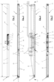
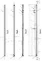
- guides (1) of guide devices according to the present invention are illustrated. By means of each of these guides (1), the movement of a corresponding rapier bar (3) in a rapier weaving machine may be guided.
- corresponding guide devices also comprise a support structure (not shown) by means of which this guide (1) is attachable to a rapier weaving machine.
- this guide (1) is attachable to a rapier weaving machine.
- each of these guides (1) is provided with mounting slots (15).
- these guide devices may also comprise one or more additional corresponding guides (1) for guiding one or more additional rapier bars (3).
- the movement trajectory of a rapier bar (3) in a rapier weaving machine is guided.
- the rapier bar (3) is driven in the rapier weaving machine by means of drive means (4) to introduce a rapier with a weft yarn in a shed between warp yarns in order to form a fabric.
- the rapier bar (3) is to this end provided with a gear rack and the drive means comprise a gear wheel (4) which engages in this gear rack.
- the movement trajectory of the rapier bar (3) is guided by the guide (1) on only one side. In this case, this is the side opposite the side on which the gear wheel (4) engages with the rapier bar (3). In alternative embodiments, it is also possible to guide the movement trajectory of the rapier bar (3) on several sides.
- a said rapier band is provided instead of the illustrated rapier bar, the movement trajectory only has to be provided for the part of the illustrated guide (1) between the gear wheel (4) and the fabric. Additional cooling may then also be provided in the complete arc where the gear wheel (4) and the rapier band engage with each other.
- the guide (1) comprises a first guide element (2) which is configured as an air-guide element (10) and a second guide element (2) in which this air-guide element (10) is accommodated.
- this second guide element (2) is provided with a receiving cavity (20) corresponding with the air-guide element (10).
- a front part (18) of this second guide element (2) extends in front of the air-guide element (10) and a rear part (19) of this second guide element (2) extends behind the air-guide element (10).
- such separate guide elements (2) may be securely fitted with respect to the air-guide element (10) or be arranged so as to be displaceable with respect to this air-guide element (10). In this case, these may be arranged so as to adjoin the air-guide element (10) or may be arranged at an intermediate distance from this air-guide element (10).
- One or more of such separate guide elements (2) may also be configured as an air-guide element (10).
- the guide (1) in the first embodiment also comprises a third guide element (2) which, in the mounted position, as illustrated in Fig. 1 , is arranged on the side of the guide rod (3) opposite the other guide elements (2) of this guide.
- the guide (1) in the form of various guide elements (2), it is possible to produce one guide element (2) (in the illustrated first embodiment the air-guide element) for different types of guides (1) in an identical manner, while it is also possible to produce different types of guides (1) by supplementing this guide element (2) with other guide elements, for example having different cooling options and/or different dimensions and/or different guiding options, etc.
- the guide (1) comprises exactly one guide element (2).
- This guide element (2) is provided for guiding a rapier bar (3) in a similar way to the guide (1) from Fig. 1 without an additional guide element (2) which is arranged on a side of the rapier bar (3) opposite the other guide elements (2).
- this guide element (2) could also be supplemented with such an additional guide element (2).
- the illustrated guide element (2) is configured as an air-guide element (10).
- the guides (1) are provided to be fixedly arranged in a rapier weaving machine.
- Each illustrated air-guide element (10) is provided with an air circuit (5) which is produced by the following:
- such channels could also be 3D-printed and/or be produced via extrusion and/or pultrusion.
- a connection (12) is provided on the access channel (23) in order to couple the air-guide element (10) with the central compressed-air device of the rapier weaving machine.
- air is thus forced through the perforations (7) in order to cool the rapier bar (3) by means of this compressed air.
- the access channel (23) is preferably provided as close as possible to the rear side of the corresponding guide element (10), so that the connection (12) with the central compressed-air device may be provided as close as possible to this central compressed-air device.
- the connection (12) is coupled to a compressed-air line (6) in order to couple it to the central compressed air device.
- the perforations (7) are arranged in an air-guiding zone (Z) which has a shorter length (l) than the length (L) along which the guide (1) extends.
- this air-guiding zone (Z) is situated at the location of the gear wheel (4).
- the length 1 of the air-guiding zone (Z) is virtually half the length (L) of the guide.
- the gear wheel (4) at the location of the gear wheel (4) a larger concentration of these perforations is present and, on the other hand, at the location of the end (14) of the guide (1) on its front side, as may be seen in Figs. 12, 13 and 17 .
- each illustrated guide element (2) is drilled into each illustrated guide element (2) via the ends and side walls of these guide elements (2) and these water channels (17) are closed.
- access channels (24) to these water channels (17) are drilled in order together to form a water circuit (8) in this guide element (2).
- subcircuits (8a, 8b, 8c) are formed in each case in the first embodiment which are mutually couplable to external couplings (11), as may be seen in Fig. 4 , in order together to form a water circuit (8) in the guide (1).
- one single water circuit (8) is provided.
- the water circuit (8) in each case extends over virtually the entire length (L) of the guide (1).
- these may alternatively and/or additionally also be 3D-printed and/or be produced via extrusion and/or pultrusion.
- Each of the water circuits (8) is provided with two connections (13) in order to be able to couple this water circuit (8) with water lines (9) (see Fig. 4 ) in order to incorporate this in the central water circuit of the rapier weaving machine.
- These connections (13) are preferably provided as close as possible to the rear side of the guides (1) in order thus to keep the connections with the central water circuit as far as possible from the fabric to be woven.
- these connections (13) are preferably arranged in the rear side of the guide (1), as is the case with the third embodiment. Both connections (13) may interchangeably be used as an inlet or as an outlet for the water circuit (8).
- the rapier bar (3) When water from the central water circuit flows through the water circuit (8), the rapier bar (3) may be water-cooled.
- the air-guide element (10) from the first embodiment is furthermore provided with cooling ribs (25) in order to increase the cooling surface of this air-guide element (10).
Landscapes
- Engineering & Computer Science (AREA)
- Textile Engineering (AREA)
- Looms (AREA)
Claims (16)
- Führungsvorrichtung, umfassend eine Führung (1) mit einem oder mehreren Führungselementen (2) zum Führen einer Greiferstange (3) in einer Greiferwebmaschine, wobei diese Führungsvorrichtung mit einem Luftkreislauf (5) versehen ist, durch den Druckluft strömen kann und der mit Perforationen (7) zum Kühlen der Greiferstange (3) mittels Druckluft versehen ist, dadurch gekennzeichnet, dass die Führungsvorrichtung mit einem Kühlkreislauf (8) versehen ist, durch den Kühlflüssigkeit zum Kühlen der Greiferstange (3) mittels Kühlflüssigkeit strömen kann.
- Führungsvorrichtung nach Anspruch 1, dadurch gekennzeichnet, dass die Führung (1) einen oder mehrere Teilkreisläufe (8a, 8b, 8c) des Kühlkreislaufs (8) umfasst.
- Führungsvorrichtung nach Anspruch 1 oder 2, dadurch gekennzeichnet, dass sich die Führung (1) in eine Längsrichtung entlang einer Länge (L) zum Führen der Greiferstange (3) erstreckt, und dadurch, dass die Führungsvorrichtung mindestens eine Luftführungszone (Z) umfasst, in dem die Perforationen (7) angeordnet sind, wobei die Luftführungszone (Z) in der Führung (1) vorgesehen ist und sich in Längsrichtung betrachtet über eine kürzere Länge (1) als die Länge (L) der Führung (1) erstreckt und wobei sich der Kühlkreislauf (8) in Längsrichtung betrachtet vorzugsweise praktisch entlang der gesamten Länge (L) der Führung (1) erstreckt.
- Führungsvorrichtung nach einem der vorstehenden Ansprüche, dadurch gekennzeichnet, dass die Führung mehrere Führungselemente (2) umfasst.
- Führungsvorrichtung nach Anspruch 3 und 4, dadurch gekennzeichnet, dass mindestens eines der Führungselemente (2) als Luftführungselement (10) ausgelegt ist, in dem die Luftführungszone (Z) angeordnet ist.
- Führungsvorrichtung nach Anspruch 2 und 4 oder 5, dadurch gekennzeichnet, dass jedes Führungselement (2) einen Teilkreislauf (8a, 8b, 8c) des Kühlkreislaufs (8) umfasst.
- Führungsvorrichtung nach einem der Ansprüche 4 bis 6, dadurch gekennzeichnet, dass die Führungselemente (2) in Längsrichtung betrachtet zumindest teilweise hintereinander angeordnet sind.
- Führungsvorrichtung nach Anspruch 7, dadurch gekennzeichnet, dass mindestens eines der Führungselemente (2) in der Führungsvorrichtung angeordnet ist, um entlang der Längsrichtung versetzbar zu sein.
- Anordnung einer Greiferstange (3), Antriebseinrichtung (4) zum Antreiben der Greiferstange (3) und einer Führungsvorrichtung, die eine Führung (1) mit einem oder mehreren Führungselementen (2) zum Führen der Greiferstange (3) umfasst, wobei die Führungsvorrichtung mit einem Luftkreislauf (5) versehen ist, durch den Druckluft strömen kann und der mit Perforationen (7) zum Kühlen der Greiferstange (3) mittels Druckluft versehen ist, dadurch gekennzeichnet, dass die Anordnung mit einem Kühlkreislauf (8) versehen ist, durch den Kühlflüssigkeit zum Kühlen der Greiferstange (3) mittels Kühlflüssigkeit strömen kann.
- Anordnung nach Anspruch 9, dadurch gekennzeichnet, dass der Kühlkreislauf (8) der Anordnung Teil der Führungsvorrichtung ist, und dadurch, dass die Führungsvorrichtung eine Führungsvorrichtung nach einem der Ansprüche 1 bis 8 ist.
- Anordnung nach Anspruch 9 oder 10, dadurch gekennzeichnet, dass die Führungsvorrichtung eine Führungsvorrichtung nach Anspruch 3 ist, und dadurch, dass sich die Luftführungszone (Z) zumindest an der Position der Antriebseinrichtung (4) erstreckt, vorzugsweise, in Längsrichtung betrachtet, praktisch entlang der verbleibenden Länge der Führung (1) auf einer Seite der Antriebseinrichtung (4).
- Anordnung nach einem der Ansprüche 9 bis 11, dadurch gekennzeichnet, dass die Führung mehrere Führungselemente (2) umfasst, dessen mindestens eines Führungselement (2) ein Führungselement (2) ist, in dem sich der Kühlkreislauf (8) teilweise erstreckt, und das auf einer Seite der Greiferstange (3) angeordnet ist, die der Seite der Greiferstange (3) entgegengesetzt ist, auf der die anderen Führungselemente (2) angeordnet sind.
- Greiferwebmaschine zum Weben eines Gewebes, dadurch gekennzeichnet, dass die Greiferwebmaschine eine Anordnung nach einem der Ansprüche 9 bis 12 umfasst.
- Greiferwebmaschine nach Anspruch 13, dadurch gekennzeichnet, dass die Führungsvorrichtung der Anordnung der Greiferwebmaschine eine Führungsvorrichtung nach Anspruch 3 ist, und dadurch, dass sich die Luftführungszone (Z) auf der Seite des zu webenden Gewebes, zumindest am Ende (14) der Führung (1), erstreckt.
- Greiferwebmaschine nach Anspruch 14, dadurch gekennzeichnet, dass die Anordnung eine Anordnung nach Anspruch 11 ist, und dadurch, dass die Seite der Antriebseinrichtung (4) dem zu webenden Gewebe zugewandt ist.
- Greiferwebmaschine nach Anspruch 14 oder 15, dadurch gekennzeichnet, dass die Anordnung eine Anordnung nach Anspruch 12 ist, und dadurch, dass das mindestens eine Führungselement (2), in dem sich der Kühlkreislauf (8) teilweise erstreckt, und das auf der Seite der Greiferstange (3) angeordnet ist, die der Seite der Greiferstange (3) entgegengesetzt ist, auf der die anderen Führungselemente (2) angeordnet sind, in der Nähe des Endes (14) der Führung (1) auf der Seite des zu webenden Gewebes angeordnet ist.
Applications Claiming Priority (2)
| Application Number | Priority Date | Filing Date | Title |
|---|---|---|---|
| BE20195298A BE1027262B1 (nl) | 2019-05-07 | 2019-05-07 | Geleidingsinrichting voor een grijperstang en grijperweefmachine omvattende een dergelijke geleidingsinrichting |
| PCT/IB2020/054129 WO2020225682A2 (en) | 2019-05-07 | 2020-05-01 | Guide device for a rapier bar and rapier weaving machine comprising such a guide device |
Publications (2)
| Publication Number | Publication Date |
|---|---|
| EP3966375A2 EP3966375A2 (de) | 2022-03-16 |
| EP3966375B1 true EP3966375B1 (de) | 2023-09-06 |
Family
ID=66630063
Family Applications (1)
| Application Number | Title | Priority Date | Filing Date |
|---|---|---|---|
| EP20723562.3A Active EP3966375B1 (de) | 2019-05-07 | 2020-05-01 | Führungsvorrichtung für eine greiferstange und greiferwebmaschine mit einer solchen führungsvorrichtung |
Country Status (5)
| Country | Link |
|---|---|
| US (1) | US11746449B2 (de) |
| EP (1) | EP3966375B1 (de) |
| CN (1) | CN113710840A (de) |
| BE (1) | BE1027262B1 (de) |
| WO (1) | WO2020225682A2 (de) |
Families Citing this family (2)
| Publication number | Priority date | Publication date | Assignee | Title |
|---|---|---|---|---|
| BE1028436B1 (nl) * | 2020-06-25 | 2022-01-31 | Vandewiele Nv | Geleidingsinrichting in een grijperweefmachine, grijperweefmachine en werkwijze voor het omvormen van een grijperweefmachine |
| CN113882070A (zh) * | 2021-11-12 | 2022-01-04 | 绍兴汀冉纺织品有限公司 | 一种剑杆机剑带冷却装置 |
Family Cites Families (18)
| Publication number | Priority date | Publication date | Assignee | Title |
|---|---|---|---|---|
| CH577577A5 (de) * | 1974-12-24 | 1976-07-15 | Rueti Ag Maschf | |
| US4117869A (en) * | 1977-05-20 | 1978-10-03 | Parks-Cramer (Great Britain) Ltd. | Oil mist lubricated textile machine and method |
| CH657640A5 (de) * | 1983-03-23 | 1986-09-15 | Saurer Ag Adolph | Greiferwebmaschine. |
| WO1988007600A1 (fr) * | 1987-04-03 | 1988-10-06 | Textilma Ag | Metier a tisser a pince |
| IT1281187B1 (it) * | 1992-10-23 | 1998-02-17 | Inter Patent Limited | Dispositivo di azionamento dei nastri porta pinza per macchine per tessitura |
| CN2161626Y (zh) * | 1993-01-05 | 1994-04-13 | 陈金朝 | 纺织机剑带散热装置 |
| DE19538287C1 (de) * | 1995-10-14 | 1997-06-19 | Dornier Gmbh Lindauer | Webmaschine mit kühlbarem Greiferantrieb |
| DE19711594A1 (de) * | 1997-03-20 | 1998-09-24 | Dornier Gmbh Lindauer | Vorrichtung zur Führung und Lagerung eines Greifertragorganes in Webmaschinen |
| IT1317495B1 (it) * | 2000-05-08 | 2003-07-09 | Rigo Group S R L | Pinza estensibile per il serraggio trasversale o di testa di lastre di materiale plastico e macchina per la termoformatura in linea di |
| BE1014950A3 (nl) * | 2001-08-29 | 2004-07-06 | Wiele Michel Van De Nv | Inrichting voor het aandrijven en geleiden van een grijper van een weefmachine. |
| US6820655B2 (en) * | 2002-03-22 | 2004-11-23 | Hans Adolf Beeh | Loom and room conditioning system |
| US8542492B2 (en) * | 2009-12-10 | 2013-09-24 | Richard Anthony Dunn, JR. | Scalable up and down nesting integrated electronic enclosures with form factors including asteroids and/or dumbbells and/or approximated tessellation(s)/tiling(s) or combinations thereof with thermal management, wiring, sliding fit, manual and/or automated full range vertical to horizontal positioning, access and structural systems for individual modules and intra-and inter-planar stacks, columns, rows, arrays and associated infrastructures |
| ITMI20110376A1 (it) * | 2011-03-10 | 2012-09-11 | Wilic Sarl | Aerogeneratore raffreddato a fluido |
| CN204211911U (zh) * | 2014-11-11 | 2015-03-18 | 安吉县青云麻纺织厂 | 一种剑带加压装置 |
| BE1022754B1 (nl) * | 2015-02-26 | 2016-08-30 | Picanol Nv | Geleidingsinrichting voor een lans voor een grijperweefmachine |
| CN207494537U (zh) * | 2017-10-11 | 2018-06-15 | 合肥精显电子科技有限公司 | 一种液晶显示屏用蚀刻脱模机 |
| CN207313826U (zh) * | 2017-10-27 | 2018-05-04 | 桐乡闻道纺织有限公司 | 一种棉麻布专用剑杆织机的剑带冷却装置 |
| CN208776912U (zh) | 2018-09-07 | 2019-04-23 | 桐乡市新诺邦纺织有限公司 | 一种透气抗菌纤维窗帘布用剑杆织机的剑带冷却装置 |
-
2019
- 2019-05-07 BE BE20195298A patent/BE1027262B1/nl not_active IP Right Cessation
-
2020
- 2020-05-01 WO PCT/IB2020/054129 patent/WO2020225682A2/en not_active Ceased
- 2020-05-01 EP EP20723562.3A patent/EP3966375B1/de active Active
- 2020-05-01 US US17/606,748 patent/US11746449B2/en active Active
- 2020-05-01 CN CN202080029262.4A patent/CN113710840A/zh active Pending
Also Published As
| Publication number | Publication date |
|---|---|
| WO2020225682A2 (en) | 2020-11-12 |
| US20220220645A1 (en) | 2022-07-14 |
| EP3966375A2 (de) | 2022-03-16 |
| CN113710840A (zh) | 2021-11-26 |
| BE1027262B1 (nl) | 2020-12-08 |
| WO2020225682A3 (en) | 2020-12-24 |
| BE1027262A1 (nl) | 2020-12-02 |
| US11746449B2 (en) | 2023-09-05 |
Similar Documents
| Publication | Publication Date | Title |
|---|---|---|
| US11746449B2 (en) | Guide device for a rapier bar and rapier weaving machine comprising such a guide device | |
| US20160250909A1 (en) | Air nozzle | |
| EP3262222B1 (de) | Führungsvorrichtung eines greifers in einer greiferwebmaschine | |
| US20150034284A1 (en) | Return waterbox for heat exchanger | |
| EP0406926A1 (de) | Greiferwebmaschine mit GreiferbandfÀ¼hrung | |
| KR20160029828A (ko) | 레노 셀비지 형성 장치를 구비한 직조기 | |
| EP2064378B1 (de) | Faserträger für eine webmaschine | |
| JP6059855B2 (ja) | リンク機構およびカバー部を備えるからみ織り装置 | |
| US6058983A (en) | Jacquard-type weaving mechanism and loom equipped with such a weaving mechanism | |
| US9725831B2 (en) | Module suitable for installation in a jacquard machine | |
| EP3485071B1 (de) | Vorrichtung zum durchtrennen von schussfäden in einer webmaschine | |
| US7350542B2 (en) | Blowing nozzle for supporting a weft thread in a weaving machine | |
| CN208440759U (zh) | 一种提花机 | |
| GB2147322A (en) | Rapier looms | |
| US4706714A (en) | Mounting arrangement for a switching unit for a loom | |
| JP2006045762A (ja) | 無ひ織機により作られる織物のトリミングを織る装置 | |
| JPH11315447A (ja) | エアジェットル―ムのためのよこ入れ装置 | |
| JP2006045762A5 (de) | ||
| EP1613799B1 (de) | Antrieb für webschäfte einer webmaschine | |
| HUP0103397A2 (hu) | Borda együttes leno szövéshez, szövőszék, valamint eljárás leno szövéshez | |
| EP3292235B1 (de) | Greiferöffner für eine webmaschine | |
| US5884674A (en) | Shed holder arrangement for a weaving rotor in a series shed loom | |
| EP0841419A1 (de) | Webvorrichtung | |
| WO2020001771A1 (en) | Fabric support | |
| KR102864271B1 (ko) | 냉각구조를 갖는 드라이어 |
Legal Events
| Date | Code | Title | Description |
|---|---|---|---|
| STAA | Information on the status of an ep patent application or granted ep patent |
Free format text: STATUS: UNKNOWN |
|
| STAA | Information on the status of an ep patent application or granted ep patent |
Free format text: STATUS: THE INTERNATIONAL PUBLICATION HAS BEEN MADE |
|
| PUAI | Public reference made under article 153(3) epc to a published international application that has entered the european phase |
Free format text: ORIGINAL CODE: 0009012 |
|
| STAA | Information on the status of an ep patent application or granted ep patent |
Free format text: STATUS: REQUEST FOR EXAMINATION WAS MADE |
|
| 17P | Request for examination filed |
Effective date: 20211011 |
|
| AK | Designated contracting states |
Kind code of ref document: A2 Designated state(s): AL AT BE BG CH CY CZ DE DK EE ES FI FR GB GR HR HU IE IS IT LI LT LU LV MC MK MT NL NO PL PT RO RS SE SI SK SM TR |
|
| DAV | Request for validation of the european patent (deleted) | ||
| DAX | Request for extension of the european patent (deleted) | ||
| GRAP | Despatch of communication of intention to grant a patent |
Free format text: ORIGINAL CODE: EPIDOSNIGR1 |
|
| STAA | Information on the status of an ep patent application or granted ep patent |
Free format text: STATUS: GRANT OF PATENT IS INTENDED |
|
| INTG | Intention to grant announced |
Effective date: 20230420 |
|
| GRAJ | Information related to disapproval of communication of intention to grant by the applicant or resumption of examination proceedings by the epo deleted |
Free format text: ORIGINAL CODE: EPIDOSDIGR1 |
|
| STAA | Information on the status of an ep patent application or granted ep patent |
Free format text: STATUS: REQUEST FOR EXAMINATION WAS MADE |
|
| P01 | Opt-out of the competence of the unified patent court (upc) registered |
Effective date: 20230503 |
|
| INTC | Intention to grant announced (deleted) | ||
| RIN1 | Information on inventor provided before grant (corrected) |
Inventor name: BRUYNOGHE, KOEN Inventor name: MAES, GEERT Inventor name: HALSBERGHE, BRECHT Inventor name: VERSCHEURE, DIEDERIK |
|
| GRAP | Despatch of communication of intention to grant a patent |
Free format text: ORIGINAL CODE: EPIDOSNIGR1 |
|
| STAA | Information on the status of an ep patent application or granted ep patent |
Free format text: STATUS: GRANT OF PATENT IS INTENDED |
|
| GRAS | Grant fee paid |
Free format text: ORIGINAL CODE: EPIDOSNIGR3 |
|
| GRAA | (expected) grant |
Free format text: ORIGINAL CODE: 0009210 |
|
| STAA | Information on the status of an ep patent application or granted ep patent |
Free format text: STATUS: THE PATENT HAS BEEN GRANTED |
|
| INTG | Intention to grant announced |
Effective date: 20230717 |
|
| AK | Designated contracting states |
Kind code of ref document: B1 Designated state(s): AL AT BE BG CH CY CZ DE DK EE ES FI FR GB GR HR HU IE IS IT LI LT LU LV MC MK MT NL NO PL PT RO RS SE SI SK SM TR |
|
| REG | Reference to a national code |
Ref country code: GB Ref legal event code: FG4D |
|
| REG | Reference to a national code |
Ref country code: CH Ref legal event code: EP |
|
| REG | Reference to a national code |
Ref country code: IE Ref legal event code: FG4D |
|
| REG | Reference to a national code |
Ref country code: DE Ref legal event code: R096 Ref document number: 602020017227 Country of ref document: DE |
|
| REG | Reference to a national code |
Ref country code: LT Ref legal event code: MG9D |
|
| REG | Reference to a national code |
Ref country code: NL Ref legal event code: MP Effective date: 20230906 |
|
| PG25 | Lapsed in a contracting state [announced via postgrant information from national office to epo] |
Ref country code: GR Free format text: LAPSE BECAUSE OF FAILURE TO SUBMIT A TRANSLATION OF THE DESCRIPTION OR TO PAY THE FEE WITHIN THE PRESCRIBED TIME-LIMIT Effective date: 20231207 |
|
| PG25 | Lapsed in a contracting state [announced via postgrant information from national office to epo] |
Ref country code: SE Free format text: LAPSE BECAUSE OF FAILURE TO SUBMIT A TRANSLATION OF THE DESCRIPTION OR TO PAY THE FEE WITHIN THE PRESCRIBED TIME-LIMIT Effective date: 20230906 Ref country code: RS Free format text: LAPSE BECAUSE OF FAILURE TO SUBMIT A TRANSLATION OF THE DESCRIPTION OR TO PAY THE FEE WITHIN THE PRESCRIBED TIME-LIMIT Effective date: 20230906 Ref country code: NO Free format text: LAPSE BECAUSE OF FAILURE TO SUBMIT A TRANSLATION OF THE DESCRIPTION OR TO PAY THE FEE WITHIN THE PRESCRIBED TIME-LIMIT Effective date: 20231206 Ref country code: LV Free format text: LAPSE BECAUSE OF FAILURE TO SUBMIT A TRANSLATION OF THE DESCRIPTION OR TO PAY THE FEE WITHIN THE PRESCRIBED TIME-LIMIT Effective date: 20230906 Ref country code: LT Free format text: LAPSE BECAUSE OF FAILURE TO SUBMIT A TRANSLATION OF THE DESCRIPTION OR TO PAY THE FEE WITHIN THE PRESCRIBED TIME-LIMIT Effective date: 20230906 Ref country code: HR Free format text: LAPSE BECAUSE OF FAILURE TO SUBMIT A TRANSLATION OF THE DESCRIPTION OR TO PAY THE FEE WITHIN THE PRESCRIBED TIME-LIMIT Effective date: 20230906 Ref country code: GR Free format text: LAPSE BECAUSE OF FAILURE TO SUBMIT A TRANSLATION OF THE DESCRIPTION OR TO PAY THE FEE WITHIN THE PRESCRIBED TIME-LIMIT Effective date: 20231207 Ref country code: FI Free format text: LAPSE BECAUSE OF FAILURE TO SUBMIT A TRANSLATION OF THE DESCRIPTION OR TO PAY THE FEE WITHIN THE PRESCRIBED TIME-LIMIT Effective date: 20230906 |
|
| REG | Reference to a national code |
Ref country code: AT Ref legal event code: MK05 Ref document number: 1608673 Country of ref document: AT Kind code of ref document: T Effective date: 20230906 |
|
| PG25 | Lapsed in a contracting state [announced via postgrant information from national office to epo] |
Ref country code: NL Free format text: LAPSE BECAUSE OF FAILURE TO SUBMIT A TRANSLATION OF THE DESCRIPTION OR TO PAY THE FEE WITHIN THE PRESCRIBED TIME-LIMIT Effective date: 20230906 |
|
| PG25 | Lapsed in a contracting state [announced via postgrant information from national office to epo] |
Ref country code: IS Free format text: LAPSE BECAUSE OF FAILURE TO SUBMIT A TRANSLATION OF THE DESCRIPTION OR TO PAY THE FEE WITHIN THE PRESCRIBED TIME-LIMIT Effective date: 20240106 |
|
| PG25 | Lapsed in a contracting state [announced via postgrant information from national office to epo] |
Ref country code: AT Free format text: LAPSE BECAUSE OF FAILURE TO SUBMIT A TRANSLATION OF THE DESCRIPTION OR TO PAY THE FEE WITHIN THE PRESCRIBED TIME-LIMIT Effective date: 20230906 |
|
| PG25 | Lapsed in a contracting state [announced via postgrant information from national office to epo] |
Ref country code: ES Free format text: LAPSE BECAUSE OF FAILURE TO SUBMIT A TRANSLATION OF THE DESCRIPTION OR TO PAY THE FEE WITHIN THE PRESCRIBED TIME-LIMIT Effective date: 20230906 |
|
| PG25 | Lapsed in a contracting state [announced via postgrant information from national office to epo] |
Ref country code: SM Free format text: LAPSE BECAUSE OF FAILURE TO SUBMIT A TRANSLATION OF THE DESCRIPTION OR TO PAY THE FEE WITHIN THE PRESCRIBED TIME-LIMIT Effective date: 20230906 Ref country code: RO Free format text: LAPSE BECAUSE OF FAILURE TO SUBMIT A TRANSLATION OF THE DESCRIPTION OR TO PAY THE FEE WITHIN THE PRESCRIBED TIME-LIMIT Effective date: 20230906 Ref country code: IS Free format text: LAPSE BECAUSE OF FAILURE TO SUBMIT A TRANSLATION OF THE DESCRIPTION OR TO PAY THE FEE WITHIN THE PRESCRIBED TIME-LIMIT Effective date: 20240106 Ref country code: ES Free format text: LAPSE BECAUSE OF FAILURE TO SUBMIT A TRANSLATION OF THE DESCRIPTION OR TO PAY THE FEE WITHIN THE PRESCRIBED TIME-LIMIT Effective date: 20230906 Ref country code: EE Free format text: LAPSE BECAUSE OF FAILURE TO SUBMIT A TRANSLATION OF THE DESCRIPTION OR TO PAY THE FEE WITHIN THE PRESCRIBED TIME-LIMIT Effective date: 20230906 Ref country code: CZ Free format text: LAPSE BECAUSE OF FAILURE TO SUBMIT A TRANSLATION OF THE DESCRIPTION OR TO PAY THE FEE WITHIN THE PRESCRIBED TIME-LIMIT Effective date: 20230906 Ref country code: AT Free format text: LAPSE BECAUSE OF FAILURE TO SUBMIT A TRANSLATION OF THE DESCRIPTION OR TO PAY THE FEE WITHIN THE PRESCRIBED TIME-LIMIT Effective date: 20230906 Ref country code: SK Free format text: LAPSE BECAUSE OF FAILURE TO SUBMIT A TRANSLATION OF THE DESCRIPTION OR TO PAY THE FEE WITHIN THE PRESCRIBED TIME-LIMIT Effective date: 20230906 Ref country code: PT Free format text: LAPSE BECAUSE OF FAILURE TO SUBMIT A TRANSLATION OF THE DESCRIPTION OR TO PAY THE FEE WITHIN THE PRESCRIBED TIME-LIMIT Effective date: 20240108 |
|
| PG25 | Lapsed in a contracting state [announced via postgrant information from national office to epo] |
Ref country code: PL Free format text: LAPSE BECAUSE OF FAILURE TO SUBMIT A TRANSLATION OF THE DESCRIPTION OR TO PAY THE FEE WITHIN THE PRESCRIBED TIME-LIMIT Effective date: 20230906 Ref country code: IT Free format text: LAPSE BECAUSE OF FAILURE TO SUBMIT A TRANSLATION OF THE DESCRIPTION OR TO PAY THE FEE WITHIN THE PRESCRIBED TIME-LIMIT Effective date: 20230906 |
|
| REG | Reference to a national code |
Ref country code: DE Ref legal event code: R097 Ref document number: 602020017227 Country of ref document: DE |
|
| PG25 | Lapsed in a contracting state [announced via postgrant information from national office to epo] |
Ref country code: DK Free format text: LAPSE BECAUSE OF FAILURE TO SUBMIT A TRANSLATION OF THE DESCRIPTION OR TO PAY THE FEE WITHIN THE PRESCRIBED TIME-LIMIT Effective date: 20230906 |
|
| PLBE | No opposition filed within time limit |
Free format text: ORIGINAL CODE: 0009261 |
|
| STAA | Information on the status of an ep patent application or granted ep patent |
Free format text: STATUS: NO OPPOSITION FILED WITHIN TIME LIMIT |
|
| PG25 | Lapsed in a contracting state [announced via postgrant information from national office to epo] |
Ref country code: DK Free format text: LAPSE BECAUSE OF FAILURE TO SUBMIT A TRANSLATION OF THE DESCRIPTION OR TO PAY THE FEE WITHIN THE PRESCRIBED TIME-LIMIT Effective date: 20230906 Ref country code: SI Free format text: LAPSE BECAUSE OF FAILURE TO SUBMIT A TRANSLATION OF THE DESCRIPTION OR TO PAY THE FEE WITHIN THE PRESCRIBED TIME-LIMIT Effective date: 20230906 |
|
| 26N | No opposition filed |
Effective date: 20240607 |
|
| PG25 | Lapsed in a contracting state [announced via postgrant information from national office to epo] |
Ref country code: BG Free format text: LAPSE BECAUSE OF FAILURE TO SUBMIT A TRANSLATION OF THE DESCRIPTION OR TO PAY THE FEE WITHIN THE PRESCRIBED TIME-LIMIT Effective date: 20230906 |
|
| PG25 | Lapsed in a contracting state [announced via postgrant information from national office to epo] |
Ref country code: BG Free format text: LAPSE BECAUSE OF FAILURE TO SUBMIT A TRANSLATION OF THE DESCRIPTION OR TO PAY THE FEE WITHIN THE PRESCRIBED TIME-LIMIT Effective date: 20230906 |
|
| REG | Reference to a national code |
Ref country code: CH Ref legal event code: PL |
|
| PG25 | Lapsed in a contracting state [announced via postgrant information from national office to epo] |
Ref country code: MC Free format text: LAPSE BECAUSE OF FAILURE TO SUBMIT A TRANSLATION OF THE DESCRIPTION OR TO PAY THE FEE WITHIN THE PRESCRIBED TIME-LIMIT Effective date: 20230906 |
|
| PG25 | Lapsed in a contracting state [announced via postgrant information from national office to epo] |
Ref country code: LU Free format text: LAPSE BECAUSE OF NON-PAYMENT OF DUE FEES Effective date: 20240501 |
|
| GBPC | Gb: european patent ceased through non-payment of renewal fee |
Effective date: 20240501 |
|
| PG25 | Lapsed in a contracting state [announced via postgrant information from national office to epo] |
Ref country code: MC Free format text: LAPSE BECAUSE OF FAILURE TO SUBMIT A TRANSLATION OF THE DESCRIPTION OR TO PAY THE FEE WITHIN THE PRESCRIBED TIME-LIMIT Effective date: 20230906 Ref country code: LU Free format text: LAPSE BECAUSE OF NON-PAYMENT OF DUE FEES Effective date: 20240501 Ref country code: CH Free format text: LAPSE BECAUSE OF NON-PAYMENT OF DUE FEES Effective date: 20240531 |
|
| PG25 | Lapsed in a contracting state [announced via postgrant information from national office to epo] |
Ref country code: IE Free format text: LAPSE BECAUSE OF NON-PAYMENT OF DUE FEES Effective date: 20240501 |
|
| PG25 | Lapsed in a contracting state [announced via postgrant information from national office to epo] |
Ref country code: FR Free format text: LAPSE BECAUSE OF NON-PAYMENT OF DUE FEES Effective date: 20240531 |
|
| PG25 | Lapsed in a contracting state [announced via postgrant information from national office to epo] |
Ref country code: GB Free format text: LAPSE BECAUSE OF NON-PAYMENT OF DUE FEES Effective date: 20240501 |
|
| PGFP | Annual fee paid to national office [announced via postgrant information from national office to epo] |
Ref country code: DE Payment date: 20250521 Year of fee payment: 6 |
|
| PGFP | Annual fee paid to national office [announced via postgrant information from national office to epo] |
Ref country code: BE Payment date: 20250521 Year of fee payment: 6 |
|
| PGFP | Annual fee paid to national office [announced via postgrant information from national office to epo] |
Ref country code: TR Payment date: 20250422 Year of fee payment: 6 |
|
| PG25 | Lapsed in a contracting state [announced via postgrant information from national office to epo] |
Ref country code: CY Free format text: LAPSE BECAUSE OF FAILURE TO SUBMIT A TRANSLATION OF THE DESCRIPTION OR TO PAY THE FEE WITHIN THE PRESCRIBED TIME-LIMIT; INVALID AB INITIO Effective date: 20200501 |
|
| PG25 | Lapsed in a contracting state [announced via postgrant information from national office to epo] |
Ref country code: HU Free format text: LAPSE BECAUSE OF FAILURE TO SUBMIT A TRANSLATION OF THE DESCRIPTION OR TO PAY THE FEE WITHIN THE PRESCRIBED TIME-LIMIT; INVALID AB INITIO Effective date: 20200501 |