EP3965629B1 - Combined shower and toilet - Google Patents
Combined shower and toilet Download PDFInfo
- Publication number
- EP3965629B1 EP3965629B1 EP20739264.8A EP20739264A EP3965629B1 EP 3965629 B1 EP3965629 B1 EP 3965629B1 EP 20739264 A EP20739264 A EP 20739264A EP 3965629 B1 EP3965629 B1 EP 3965629B1
- Authority
- EP
- European Patent Office
- Prior art keywords
- shower
- toilet
- arrangement
- floor
- shower floor
- Prior art date
- Legal status (The legal status is an assumption and is not a legal conclusion. Google has not performed a legal analysis and makes no representation as to the accuracy of the status listed.)
- Active
Links
Images






Classifications
-
- A—HUMAN NECESSITIES
- A47—FURNITURE; DOMESTIC ARTICLES OR APPLIANCES; COFFEE MILLS; SPICE MILLS; SUCTION CLEANERS IN GENERAL
- A47K—SANITARY EQUIPMENT; ACCESSORIES THEREFOR, e.g. TOILET ACCESSORIES
- A47K4/00—Combinations of baths, showers, sinks, wash-basins, closets, or urinals, not covered by a single other group of this subclass
-
- A—HUMAN NECESSITIES
- A47—FURNITURE; DOMESTIC ARTICLES OR APPLIANCES; COFFEE MILLS; SPICE MILLS; SUCTION CLEANERS IN GENERAL
- A47K—SANITARY EQUIPMENT; ACCESSORIES THEREFOR, e.g. TOILET ACCESSORIES
- A47K10/00—Body-drying implements; Toilet paper; Holders therefor
- A47K10/24—Towel dispensers; Toilet paper dispensers
- A47K10/32—Dispensers for paper towels or toilet paper
- A47K10/34—Dispensers for paper towels or toilet paper dispensing from a web, e.g. with mechanical dispensing means
- A47K10/38—Dispensers for paper towels or toilet paper dispensing from a web, e.g. with mechanical dispensing means the web being rolled-up
-
- A—HUMAN NECESSITIES
- A47—FURNITURE; DOMESTIC ARTICLES OR APPLIANCES; COFFEE MILLS; SPICE MILLS; SUCTION CLEANERS IN GENERAL
- A47K—SANITARY EQUIPMENT; ACCESSORIES THEREFOR, e.g. TOILET ACCESSORIES
- A47K3/00—Baths; Showers; Appurtenances therefor
- A47K3/28—Showers or bathing douches
-
- A—HUMAN NECESSITIES
- A47—FURNITURE; DOMESTIC ARTICLES OR APPLIANCES; COFFEE MILLS; SPICE MILLS; SUCTION CLEANERS IN GENERAL
- A47K—SANITARY EQUIPMENT; ACCESSORIES THEREFOR, e.g. TOILET ACCESSORIES
- A47K3/00—Baths; Showers; Appurtenances therefor
- A47K3/28—Showers or bathing douches
- A47K3/30—Screens or collapsible cabinets for showers or baths
- A47K3/32—Collapsible cabinets
-
- A—HUMAN NECESSITIES
- A47—FURNITURE; DOMESTIC ARTICLES OR APPLIANCES; COFFEE MILLS; SPICE MILLS; SUCTION CLEANERS IN GENERAL
- A47K—SANITARY EQUIPMENT; ACCESSORIES THEREFOR, e.g. TOILET ACCESSORIES
- A47K3/00—Baths; Showers; Appurtenances therefor
- A47K3/28—Showers or bathing douches
- A47K3/30—Screens or collapsible cabinets for showers or baths
- A47K3/32—Collapsible cabinets
- A47K3/325—Collapsible cabinets movable, e.g. for easy transportation to the site of use
-
- E—FIXED CONSTRUCTIONS
- E03—WATER SUPPLY; SEWERAGE
- E03C—DOMESTIC PLUMBING INSTALLATIONS FOR FRESH WATER OR WASTE WATER; SINKS
- E03C1/00—Domestic plumbing installations for fresh water or waste water; Sinks
- E03C1/01—Domestic plumbing installations for fresh water or waste water; Sinks for combinations of baths, showers, sinks, wash-basins, closets, urinals, or the like
-
- E—FIXED CONSTRUCTIONS
- E03—WATER SUPPLY; SEWERAGE
- E03D—WATER-CLOSETS OR URINALS WITH FLUSHING DEVICES; FLUSHING VALVES THEREFOR
- E03D11/00—Other component parts of water-closets, e.g. noise-reducing means in the flushing system, flushing pipes mounted in the bowl, seals for the bowl outlet, devices preventing overflow of the bowl contents; devices forming a water seal in the bowl after flushing, devices eliminating obstructions in the bowl outlet or preventing backflow of water and excrements from the waterpipe
- E03D11/02—Water-closet bowls ; Bowls with a double odour seal optionally with provisions for a good siphonic action; siphons as part of the bowl
-
- E—FIXED CONSTRUCTIONS
- E03—WATER SUPPLY; SEWERAGE
- E03D—WATER-CLOSETS OR URINALS WITH FLUSHING DEVICES; FLUSHING VALVES THEREFOR
- E03D11/00—Other component parts of water-closets, e.g. noise-reducing means in the flushing system, flushing pipes mounted in the bowl, seals for the bowl outlet, devices preventing overflow of the bowl contents; devices forming a water seal in the bowl after flushing, devices eliminating obstructions in the bowl outlet or preventing backflow of water and excrements from the waterpipe
- E03D11/02—Water-closet bowls ; Bowls with a double odour seal optionally with provisions for a good siphonic action; siphons as part of the bowl
- E03D11/025—Combined with wash-basins, urinals, flushing devices for chamber-pots, bed-pans, or the like
-
- E—FIXED CONSTRUCTIONS
- E03—WATER SUPPLY; SEWERAGE
- E03D—WATER-CLOSETS OR URINALS WITH FLUSHING DEVICES; FLUSHING VALVES THEREFOR
- E03D11/00—Other component parts of water-closets, e.g. noise-reducing means in the flushing system, flushing pipes mounted in the bowl, seals for the bowl outlet, devices preventing overflow of the bowl contents; devices forming a water seal in the bowl after flushing, devices eliminating obstructions in the bowl outlet or preventing backflow of water and excrements from the waterpipe
- E03D11/13—Parts or details of bowls; Special adaptations of pipe joints or couplings for use with bowls, e.g. provisions in bowl construction preventing backflow of waste-water from the bowl in the flushing pipe or cistern, provisions for a secondary flushing, for noise-reducing
- E03D11/14—Means for connecting the bowl to the wall, e.g. to a wall outlet
- E03D11/143—Mounting frames for toilets and urinals
-
- A—HUMAN NECESSITIES
- A47—FURNITURE; DOMESTIC ARTICLES OR APPLIANCES; COFFEE MILLS; SPICE MILLS; SUCTION CLEANERS IN GENERAL
- A47K—SANITARY EQUIPMENT; ACCESSORIES THEREFOR, e.g. TOILET ACCESSORIES
- A47K10/00—Body-drying implements; Toilet paper; Holders therefor
- A47K10/16—Paper towels; Toilet paper; Holders therefor
- A47K10/18—Holders; Receptacles
- A47K10/22—Holders; Receptacles for rolled-up webs
-
- A—HUMAN NECESSITIES
- A47—FURNITURE; DOMESTIC ARTICLES OR APPLIANCES; COFFEE MILLS; SPICE MILLS; SUCTION CLEANERS IN GENERAL
- A47K—SANITARY EQUIPMENT; ACCESSORIES THEREFOR, e.g. TOILET ACCESSORIES
- A47K3/00—Baths; Showers; Appurtenances therefor
- A47K3/26—Bidets without upward spraying means
-
- E—FIXED CONSTRUCTIONS
- E03—WATER SUPPLY; SEWERAGE
- E03D—WATER-CLOSETS OR URINALS WITH FLUSHING DEVICES; FLUSHING VALVES THEREFOR
- E03D11/00—Other component parts of water-closets, e.g. noise-reducing means in the flushing system, flushing pipes mounted in the bowl, seals for the bowl outlet, devices preventing overflow of the bowl contents; devices forming a water seal in the bowl after flushing, devices eliminating obstructions in the bowl outlet or preventing backflow of water and excrements from the waterpipe
- E03D11/13—Parts or details of bowls; Special adaptations of pipe joints or couplings for use with bowls, e.g. provisions in bowl construction preventing backflow of waste-water from the bowl in the flushing pipe or cistern, provisions for a secondary flushing, for noise-reducing
Definitions
- the present invention relates to a combined shower and toilet.
- arrangement is a technical term which means a feature, or combination of features, (usually with a given purpose).
- a 'measuring arrangement' is a feature or features, to facilitate measuring.
- a 'holding arrangement' is a feature or features, to facilitate holding.
- a feature is a broad term that includes within its scope any feature under the Sun.
- a feature may, for example, be an element, body, member, or may even be an aperture (eg opening/hole/gap or the such like).
- the term 'holding feature' includes within its scope, for example, any element, body, member, or even aperture, to facilitate holding.
- a 'feature' may also be a 'part' of a broader feature; for example, if a part of an invention is disclosed/claimed as comprising a 'padding feature', this does not limit the padding feature to being a separate feature that is added to the invention (eg a sponge element, adhered to the invention); the invention, for example, may have a part made of sponge, or have an inner sponge (or soft) layer- in such a case, if that part of the invention is clearly of a material/nature that provides padding, then this falls within a scope of what is defined in the present application as a 'padding feature'.
- a feature (or two features) are defined in a claim as being attached, that would include within its scope the feature (or two features) being permanently attached, (of course), and would also include within its scope the feature (or two features) being removably attachable, (because, if removably attachable, the feature (or two features) can be attached, and therefore, when attached, would be within a scope of being 'attached').
- the feature (or two features) being defined in a claim as being 'attached' would also include within its scope the feature that is defined as being 'attached' being formed as one part with a portion or a whole of the other feature it is defined as being 'attached' to.
- a table leg is defined in a claim as being 'attached' to a table top, that would include within its scope the table leg being formed as one part with a whole of the table top (eg if the table leg and table top were formed as one piece of plastic, for example) and would also include within its scope the table leg being formed as one part with a portion (rather than a whole) of the table top (eg if the table top was formed of more than one part, and the table leg was formed as one part with a part of the table top, but not a whole of it).
- 'Indirect' connection would be where two features, for example, are connected, but via intermediate feature(s) (eg a person's foot is 'connected' to their head, but 'indirectly', (via their leg, abdomen, torso, etc, which are 'intermediate features')).
- intermediate feature(s) eg a person's foot is 'connected' to their head, but 'indirectly', (via their leg, abdomen, torso, etc, which are 'intermediate features'
- 'connected' is used in a claim, it includes within its scope 'direct' connection, and also includes within its scope 'indirect' connection.
- the term may be used in a claim, (and is deemed supported), whether 'direct' and/or 'indirect' connection embodiment(s) is (/are) disclosed in the present application, and, as stated, includes within its scope 'direct' connection, and also includes within its scope 'indirect' connection.
- a feature(s) is (/are) defined as being 'connected', that would include within its scope the (or any- ie more than one of the said) feature(s) being removably attachable, if, when attached, the feature(s) is (/are) in a state of being 'connected', (directly or indirectly).
- a first feature is defined as being 'connected' to a second feature, it would include within its scope the first feature and/or the second feature being removably attachable, if, when attached, the first feature is connected to the second feature, (directly or indirectly).
- the term 'the or each' can refer back to a single feature/thing, and/or can refer back to a plurality of features/things.
- the term should be taken as meaning, and including within its scope, 'at least one, or more, or all (ie each)' of the said features/things.
- a square is referred to/disclosed that has four corners, if the term 'the or each corner' is used, it includes within its scope 'one of the corners, (or two, or three, or all of the corners)'.
- any one feature/thing is afforded any feature(s)/definition in the present application, it is taken as read that, where a plurality of the said feature/thing is provided, 'the or each' said feature/thing may be provided/claimed comprising the said feature(s)/definition (ie at least one, or more or all).
- the term 'the or any' may be used (again including within its scope, 'at least one, or more, or all (ie each)', instead of the term 'the or each').
- a 'user means' to turn on a television could be provided by way of an ON/OFF button on the television. But it could also be provided by a button on a remote control which turns on the television when pressed. Both of these would fall (in the technical field of product design/user-interface) under the scope of the term 'user means' to turn on the television.
- a 'user means' may be provided to 'initiate' an action, for example.
- a claim that defines an invention which comprises a 'user means' for [a particular action/result] is not subject to any 'means for' limitations that certain patent office territories (such as the United States) may appropriate to the term 'means for', but should be read as (and given protection for, if granted) any means under the sun, provided for a user, for [that particular action/result defined].
- 'User means' is a technical term in the field of product design/user-interface.
- a first side of the/an invention may be numbered 600', and a second side of the/an invention numbered 600".
- a suffix such as 'L' and 'R' to denote 'left' and 'right', or 'a' and 'b', for example
- the plural when such features are referred to together (ie 'the sides'), the plural may be numbered/referred to with the primary number (without the suffix).
- the first side 600' and second side 600" may, for example, be referred to simply as 'the sides 600'.
- the primary number ie 600, for example
- the primary number may be used, without any suffix.
- Document FR 1.032.764 discloses a combined shower and toilet arrangement. For various reasons, (including the ability to save space, which could be extremely useful (and valuable)), it would be desirable if a solution could be provided, to allow for usage both of a toilet, and a shower, whilst saving space.
- the present invention seeks to provide a solution to any or all of the above problem(s), by providing: a combined shower and toilet arrangement, comprising: a shower, comprising: a shower fluid outputting arrangement; and a shower floor; and: a toilet, comprising a receiving area for receiving human waste; wherein the combined shower and toilet arrangement is operable in a shower use mode or a toilet use mode, wherein: in the toilet use mode, the shower floor is in a position that does not obstruct use of the toilet and is in a non-use position, not usable as a floor for the shower; and in the shower use mode, the shower floor is in a shower use position, above a portion or a whole of the receiving area of the toilet, and is usable as a floor for the shower.
- toilets to defecate into tend to always have a raised unit (raised from the ground), comprising a seat and a basin (the basin is often also referred to/defined as a 'pan') for the user to defecate into, (and tend to have flushing systems, to evacuate the waste), even toilets that tend to be of a much more basic structure (eg what are often referred to as 'squat' toilets), which may not be (or may hardly be) raised from the ground, and where the user may 'squat' and defecate into a hole that is substantially at ground level, and which are prevalent in some parts of the world) are within the scope of being a toilet. (It will be apparent that many different toilets may also be used for urinating into).
- the term 'toilet' also does
- the shower fluid will tend, (in nearly all cases), to just be water. However, it could feasibly be a mix, including, for example, cleaning agents, (such as soap, etc, which may aid cleaning of the user).
- cleaning agents such as soap, etc, which may aid cleaning of the user.
- the combined shower and toilet arrangement may be particularly useful in small living areas, (such as condominiums or hotel rooms, for example). It could also be useful/appropriate for office facilities, to enable staff to shower, eg following physical efforts coming into work, such as cycling. A shower and toilet could therefore be provided, in such a case, in a very limited space. (However, it should be stated, the combined shower and toilet arrangement is not limited to small living spaces).
- the shower floor is rotatably movable from the non-use position to the shower use position; and from the shower use position to the non-use position.
- the shower floor is rotatably movable from the non-use position to the shower use position, and from the shower use position to the non-use position, rotatably movable from behind the receiving area of the toilet.
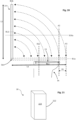
- Fig. 2B of EGHFAIER looking at Fig. 2B of EGHFAIER, one can see that the shower floor of EGHFAIER is in a raised position.
- Fig. 2A of EGHFAIER One can see, (by virtue of Fig. 2A of EGHFAIER ) that, when rotated down from this position, the whole of the receiving area of the toilet is not 'within a circular trajectory of an arc of rotation of the shower floor as it rotates from the non-use position to the shower use position'. This is clear, because we can even clearly see the receiving area of the toilet in Fig.
- a combined shower and toilet arrangement has the potential to save a lot of space, (especially over having a separate toilet and shower). For this reason, it may be particularly desired where space-saving is at a premium.
- Examples of this may include, for example, novelty compact hotels, or extreme compact-housing type housing, which has becomes more popular in recent times, and often includes individually-built (although it could include mass-produced) housing, which uses many tricks (in terms of design, engineering, etc) to build a liveable space in extremely compact dimensions.
- _Other benefits may include, for example, in transportable embodiments. For example, is a transportable embodiment(s) is used at a festival(s), it may be extremely beneficial if the whole unit is extremely compact.
- Rotation of the shower floor being configured so that a whole of the receiving area of the toilet is within a circular trajectory of an arc of rotation of the shower floor as it rotates from the non-use position to the shower use position gives a benefit (eg over EGHFAIER), because the whole unit could be extremely compact (in the front/back orientation).
- Fig. 2A of EGHFAIER it can be seen that it is not particularly compact in the front/back orientation, with the shower floor clearly extending outwards significantly at the front. This is a significant disadvantage in terms of compactness, and therefore could even be argued to slightly erode one of the main benefits of a combined shower and toilet arrangement, (ie compactness).
- a combined shower and toilet arrangement comprising: a shower; and a toilet. (All other feature(s) and/or combination of feature(s) disclosed in the present application are optional with regards to this aspect of the invention).
- the second aspect may comprise any of the feature(s) of the first aspect and may draw upon any of the feature(s) and/or disclosure of the present application, as optional and/or preferable feature(s).
- Any aspect may comprise any feature(s) of any other aspect(s), whether the feature(s) be essential or preferable and/or optional to the other aspect(s).
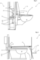
- a combined shower and toilet arrangement 10 comprising: a shower, comprising: a shower fluid outputting arrangement 12; and a shower floor 14; and: a toilet 16, comprising a receiving area 19 for receiving human waste; wherein the combined shower and toilet arrangement is operable in a shower use mode or a toilet use mode, wherein: in the toilet use mode, the shower floor is in a position that does not obstruct use of the toilet, and is in a non-use position, not usable as a floor for the shower; and in the shower use mode, the shower floor 14 is in a shower use position, above a portion or a whole of the receiving area of the toilet 16, and is usable as a floor for the shower.
- the shower fluid outputting arrangement 12 comprises a shower head, (best shown in Fig. 1 and Fig. 2 ).
- the shower fluid outputting arrangement 12 could be provided in many different ways, in no way limited to the example of a shower head.
- water may be outputted directly from the/a wall, onto the shower user in the shower.
- This again, despite being very different from a shower head, would be an example of a shower fluid outputting arrangement 12.
- the fluid could feasibly be outputted from just one opening (and thus aperture), rather than a plurality (of apertures).
- the combined shower and toilet arrangement 10 may comprise any of the features associated with everyday showers; for example, it may have a handheld shower head, for example, (for use as part of shower fluid outputting arrangement 12). It may also comprise various shower fittings, (including taps, dials, etc)).
- shower heads tend to comprise a plurality of outputting apertures (and thus fluid is outputted from the shower fluid outputting arrangement 12 via many apertures, (in a standard 'sprinkler' type outputting that is typical in many showers), it is feasible, for the combined shower and toilet arrangement, that fluid is outputted from just one aperture, rather than a plurality of apertures)).
- the fluid outputting arrangement may be positioned differently, which will be apparent).
- the or any shower fittings may include traditional fixtures and fittings associated with any other shower, for example.
- a shower head for example.
- a hand-held shower head
- the receiving area 19 of the example toilet 16 is clearly shown.
- the toilet comprises a pan 18.
- the receiving area 19 is a receiving area of a pan.
- not all toilets comprise a pan.
- 'squat' toilets may or may not comprise a pan. (And if they (squat toilets) do comprise a pan, it will tend not to be a 'raised' (above ground) pan, as in the example of Fig. 5 ).
- the receiving area 19, (depending on whether the toilet embodiment comprises a pan), may or may not be a receiving area of a pan.
- the shower floor may be movable (from the shower use position to the toilet use position) in any way; for example, in a most basic embodiment, the shower floor may be movable by a user as a separate part from the rest of the combined shower and toilet arrangement.
- the user could put the shower floor in the shower use position, to use the combined shower and toilet arrangement as a shower, and could then remove the shower floor, perhaps placing it on the bathroom floor, or leaning it against the bathroom wall, or storing it anywhere, so that the combined shower and toilet arrangement can then be used in the toilet use mode.
- this may be cumbersome. (In such a case/example, wherever the shower floor is placed/stored by the user when removed, that is the/a 'non-use position' of the shower floor).
- the combined shower and toilet arrangement comprises a mechanism to facilitate moving the shower floor from the non-use use position to the shower use position.
- the combined shower and toilet arrangement comprises a mechanism to facilitate moving the shower floor from the non-use use position to the shower use position).
- the shower floor is rotatably movable from the non-use position to the shower use position.
- This is shown, by way of example only, in the drawings, and is best shown by virtue of the comparison between the position of the shower floor 14 in Fig. 1, and Fig. 2 , where it has been shown rotatably moved from the shower use position ( Fig. 1 ) to the non-use use position ( Fig. 2 ).
- the combined shower and toilet arrangement comprises a rotation arrangement, to facilitate the shower floor being rotatably movable from the non-use position to the shower use position. (As stated, this is shown, by way of example only, in the drawings, and is best shown by virtue of the comparison between the position of the shower floor 14 in Fig. 1, and Fig. 2 , where it has been shown rotatably moved from the shower use position ( Fig. 1 ) to the non-use use position ( Fig. 2 )).
- the term 'mechanism' for the sake of the present application, is a broad term.
- the term 'mechanism to facilitate moving the shower floor from the non-use use position to the shower use position' includes within its scope any arrangement to facilitate moving the shower floor from the non-use use position to the shower use position.
- Any mechanism need not be complex, and may be extremely simple in nature, (or may feasibly be more complex in nature).
- the term 'rotation arrangement' (to facilitate the shower floor being rotatably movable from the non-use position to the shower use position) is here used, (rather than the term 'rotation mechanism'), simply to avoid any person(s) reading undue limitation on the term 'mechanism'.
- the term 'mechanism' in the present application, is an extremely broad term.
- any example of a rotation arrangement (to facilitate the shower floor being rotatably movable from the non-use position to the shower use position) is also considered to be an example of a rotation 'mechanism' (to facilitate the shower floor being rotatably movable from the non-use position to the shower use position), (thereby comprising a feature or features, to facilitate the shower floor being rotatably movable from the non-use position to the shower use position), however simple or complex it may be.
- an extremely simple mechanism would be within this scope.
- a portion of the shower floor partially or wholly surrounds a feature(s) (eg a cylindrical feature/element, for example, or any relevant shape/feature(s)), and either the shower floor (by virtue of partially or wholly surrounding the feature(s)) can rotate around the feature(s), (and/or the feature(s) that is partially or wholly surrounded (or connected to (by the shower floor) in any way, for example) itself may be able to rotate, (thus facilitating rotation of the shower floor).
- a feature(s) eg a cylindrical feature/element, for example, or any relevant shape/feature(s)
- a rotation arrangement to facilitate the shower floor being rotatably movable from the non-use position to the shower use position
- this may also be said to be an example of a rotation mechanism, to facilitate the shower floor being rotatably movable from the non-use position to the shower use position.
- the rotation arrangement (and hence the rotation mechanism) comprise a hinge(s), which is an example provided by way of example only.
- the combined shower and toilet arrangement comprising a rotation arrangement, to facilitate rotatably moving the shower floor, (from the shower use position to the non-use position, (and vice versa)).
- the rotation arrangement may comprise a hinge(s).
- An example hinge 15 (and/or hinge fulcrum area 15) is shown and denoted in various of the Figures.
- the rotation arrangement comprises a hinge mechanism.
- FIG. 6 An example of a hinge(s) 15 is also shown in Fig. 6 . All the examples shown show examples of a mechanism to facilitate moving the shower floor from the non-use position to the shower use position (and thus vice versa).
- Mechanisms to facilitate moving the shower floor from the non-use position to the shower use position are not limited to being to facilitate rotation.
- the shower floor could be slid out of a wall (eg horizontally), and therefore could be slid from the non-use position (eg in a cavity/recess of the wall) to the shower use position, (and vice versa).
- this would be an example of a slide arrangement.
- movement of the shower floor is not limited to being done via rotation.
- the shower floor is able to extend beyond vertically. (This can allow it to simply use gravity to stay in the non-use position, whereas, if the shower floor did not extend beyond vertical, it may or would fall back down). (Best example shown of the shower floor extending beyond vertical in the non-use position is in Fig. 1 , although Fig. 5 also shows this clearly).
- the shower floor 14 is behind a portion or a whole of the pan 18 of the toilet.
- a whole of the shower floor 14 is behind a portion or a whole of the pan 18 of the toilet 16, in the toilet use mode.
- the term 'behind' refers to, from a front view (ie from the view as shown in Fig. 4 ), a portion or a whole of the shower floor being behind the pan of the toilet.
- the term is not necessarily 'height' relevant, and, (in the non-use position), a portion or a whole of the shower floor (as shown in Fig. 4 , for example, and other Figures) may be higher than the height of the pan of the toilet).
- the shower floor 14 (in its non-use position) is substantially parallel to the back wall behind the toilet.
- the term 'substantially parallel' means within twenty degrees of parallel. (Preferably it is within ten degrees of parallel).
- a wall 21 (eg back wall) of the combined shower and toilet arrangement and a wall 20 of the room are the same wall/feature.
- feature 21 and 20 could, in a different embodiment, be the same (ie just one) wall.
- Any features (such as the water/flush system, for example) shown between wall 20 and wall 21 could, in such an example, then be hidden, for example, behind and/or within that same wall that provides features 20 and 21.
- This example is given by way of example only, simply to display that various options are possible.
- a wall 21 (which in the example is a back wall) for/of the shower.
- the combined shower and toilet arrangement 10 may comprise a holding arrangement, to hold the shower floor 14 in the non-use position.
- a holding arrangement to hold the shower floor 14 in the non-use position.
- an example holding arrangement is provided, and is shown holding the shower floor to a back of the shower.
- an example back 21 of the shower is shown in Fig. 1 and Fig. 2 ).
- the example holding arrangement comprises a clip(s) 23, which hold the shower floor in the non-use position.
- the shower floor may stay in the non-use position merely due to gravity, if it extends beyond vertical in the non-use position.
- a holding arrangement may not be required.
- the example holding arrangement is shown comprising a plurality of clips, but may feasibly comprise only one).
- the holding arrangement may comprise latch(es), and/or may be magnetic, etc, etc.
- many different types of holding arrangements are possible, not limited to the examples shown and/or disclosed).
- a portion or a whole of the shower floor is sloped to facilitate drainage of water from the shower floor.
- FIG. 6 for example, (and also in Fig. 1 ), wherein the shower floor can clearly be seen angled downward, from front to back.
- FIG. 6 where the shower floor 14 clearly is angled downward from front (from the right side of the Figure) to back, (to the left side of the Figure).
- this feature is provided in all of the embodiments of the Figures).
- a whole of the shower floor is angled. However, it is feasible just a portion (rather than a whole) is angled, to facilitate drainage.
- a portion or a whole' of the shower floor may be sloped, because, whilst in the examples shown, a whole of the shower floor is angled (and is thus an example of a whole of the shower floor being sloped), it will be apparent that embodiments may be provided where not all of the shower floor is sloped, but rather a portion is sloped, to facilitate drainage of water from the shower floor.
- some of the shower floor is flat (and is not sloped), but that a part of the surface of the shower floor is sloped, for example, and that this facilitates drainage of water from the shower floor.
- a portion or a whole of the shower floor may be sloped, to facilitate drainage of water from the shower floor.
- the whole shower floor is angled.
- the shower floor is horizontal/flat (eg on its underside), but is shaped in such a way (eg with a portion or a whole of its top surface being sloped, to facilitate drainage), to facilitate drainage. All such embodiments are within a scope of 'a portion or a whole of the shower floor being sloped', to facilitate drainage).
- water from the shower floor is directed, (in some way). (Feature(s) to facilitate this may be referred to as 'an arrangement to direct water from the shower floor'), (which itself may be referred to as a 'flow arrangement, to direct water from the shower floor')).
- water from the shower floor is directed into a water system of the toilet.
- the combined shower and toilet arrangement comprises a flow arrangement, to direct water from the shower floor, into a water system of the toilet).
- the flow arrangement is a flow arrangement to direct water from the shower floor, into a pan of the toilet.
- the flow arrangement may feasibly direct water from the shower floor into other area(s) of the water system of the toilet, (rather than, (or in combination to) the pan of the toilet).
- it may feasibly direct water into a pipe(s), (eg a waste pipe(s)), of the water system of the toilet.
- the flow arrangement could, for example, be as simple as an aperture arrangement in the shower floor.
- the toilet is shown comprising an example lid 38.
- the/a toilet may, or may not, comprise a lid). If the pan of the toilet is open, (eg from the lid being open, or simply by virtue of the toilet not having a lid), then if there is an aperture arrangement in the shower floor, (eg a hole(s), for example), then water from the shower can drain through the aperture arrangement, and into the basin of the toilet.
- aperture arrangement' simply means 'one or more apertures'. For example, there could be more than one aperture (eg hole) in the shower floor, for water to drain through).
- the combined shower and toilet arrangement comprises a channel arrangement (ie one or more channel(s)), through which water from the shower is directed.
- a channel arrangement ie one or more channel(s)
- the flow arrangement comprises one or more channel, (and thus comprises at least one channel 24).
- the or any channel may be fully enclosed.
- the or any channel may be open.
- an open channel of this type would not be a 'tube', it is nevertheless an embodiment of a channel.
- FIG. 5 and Fig. 6 clearly show an example of a channel arrangement, through which water from the shower is directed into the example pan of the toilet. However, in other examples, there may be provided a channel arrangement, through which water from the shower is directed, into any other part(s) of the water system of the toilet).
- the toilet is a flushable toilet
- the flow arrangement, to direct water from the shower floor, into a water system of the toilet is an example of a flow arrangement, to direct water from the shower floor, into a water flush system of the toilet).
- the combined shower and toilet arrangement comprises a catching area 26, to catch water from the shower.
- An example catching area is shown most clearly in Fig. 6 .
- a portion or a whole of the catching area is provided behind (ie further back than) the shower floor, when the shower floor is in the shower use position.
- the or any catching area comes in the form of a gutter (and thus comprises a gutter).
- a portion or a whole of the or any gutter may be located behind the shower floor).
- a portion or a whole of the shower floor is sloped so that water from the shower floor is directed towards the catching area.
- the or any catching area may be provided in the form of a bowl element, for example.
- a catching area even if there is not provided a flow arrangement to direct water from the shower floor, into a water system of the toilet.
- water from the shower could collect in a catching area, and the water and/or catching area could then be manually removed(/deposited) elsewhere, or pumped out, etc, etc) by a user, for example, (or via a mechanism(s) that may not require a user, for example).
- a catching area without water being directed into the water system of the toilet, for example
- the flow arrangement comprises a catching area, and also comprises a channel arrangement, to allow water to flow from the catching area.
- the catching area is provided partially or wholly behind the shower floor, when the shower floor is in the shower use position, in the example, and, in the example, provided wholly behind the shower floor when the shower floor is in the shower use position).
- the channel arrangement directs water into the pan of the toilet. Thus, in the example, it enters the toilet water system.
- the flow arrangement may feasibly direct water from the shower floor into other area(s) of the water system of the toilet, (rather than, (or in combination to) the pan of the toilet)).
- many toilets have a water level system whereby (ie the system is designed such that) water cannot overflow from the pan (unless there is a blockage, for example).
- the system is designed to prevent water from overflowing from the pan, as much as is possible).
- water being directed from the shower floor, into the pan of the toilet can be a very effective way of removing the water.
- a support arrangement 28 for the shower floor which, in the shower use mode, engages with a ground surface, to support the shower floor. Examples of this are shown most clearly in Fig. 1 , Fig. 3 , and Fig. 6 .
- the support arrangement may be located in any position. However, preferably a portion or a whole of the support arrangement 28, when in use supporting the shower floor in the shower use mode, is in front of the receiving area 19 (and in front of the toilet pan, if the toilet comprises a pan). (Examples of this are best shown in Fig. 1 , 3 and 6 ).
- the support arrangement 28 comprises at least one step 30.
- the support arrangement comprises an X-frame, (shown by way of example only). It is known that such support structures can provide extremely effective (ie strong) support.
- step(s) 30 is shown rotated up, with the shower floor in its non-use position).
- the support arrangement is preferably connected to the shower floor. (This may be the case permanently. In other embodiments, it may be connected removably attachably).
- the support arrangement is connected to the shower floor, and is at least one of: collapsible, (to save space in the toilet use mode); rotatable towards the shower floor, (to save space in the toilet use mode).
- collapsible to save space in the toilet use mode
- rotatable towards the shower floor to save space in the toilet use mode.
- FIG. 3 is both collapsible, and also rotatable towards the shower floor. This saves space and makes it compact, in toilet use mode).
- a toilet paper holder 32 Preferably, there is provided a toilet paper holder 32.
- a toilet paper holder 32 on an underside 34 of the shower floor 14.
- a toilet roll 33 on an example toilet roll holder, (a toilet roll holder being an embodiment of a toilet paper holder)).
- the toilet roll holder thus allows for appropriate positioning (and providing) of a toilet roll, in the toilet use mode.
- Fig. 1 shows an example of what position an example toilet roll may be in, in the shower user mode.
- the toilet roll is shielded from getting wet from any water from the shower).
- Toilet paper is not limited to being provided as a roll, and therefore the toilet paper holder is not limited to being a toilet roll holder.
- the toilet paper could be provided as stacked/layered flat sheets of toilet paper, for example.
- the toilet paper holder could, for example, comprise/be a holder for holding such sheets.
- the toilet paper holder could be a holder (eg substantially square or rectangular, for example, or any shape) that holds the sheets, and comprises an aperture, for example, through which one or more of the sheets can be pulled out of the holder, for example, for use). (This is just one example, provided by way of example only)).
- the toilet paper holder is not limited to being a toilet roll holder.
- toilet roll is used throughout much of the world.
- the toilet paper holder is a toilet roll holder.
- a toilet flush user means 36 on an underside 34 of the shower floor 14.
- the toilet flush user means may feasibly be a mechanical user means, (such as a rotatable lever, for example, which initiates flushing), this may be fairly challenging to engineer, (taking into account the movement of the shower floor).
- the toilet flush user means 36 is an electronic user means for flushing the toilet.
- the user means is a button (or any user means), for example, that the user can press, to activate the flush).
- the toilet flush user means 36 for flushing the toilet is a touchless user means.
- Touchless toilet flush user means are means that allow the user to flush the toilet, without touching the user means. They tend to work from a sensor(s), (which can sense the user's hand, for example, (or anything)). Thus a user can pass their hand, for example, in front of the user means, (to initiate flushing).
- touchless sensor flush mechanisms work by there being an electronic sensor(s), (which can sense the user's hand, for example, (or anything)). This can thus facilitate flushing, when the user's hand, for example, is in front of the touchless user means).
- flushing may be activated by proximity of the user's hand, for example, (or anything), to the user means, to activate flushing.
- Such touchless sensor flush mechanisms often then comprise a wireless receiver. (Such mechanisms are not limited to being wireless, and may function via (and thus comprise) wiring, rather than being wireless).
- the receiver having received a signal(s), the touchless sensor flush mechanisms often is configured to activate a mechanism to pull/manipulate a chain (or other mechanism), which itself causes/initiates flushing.
- the shower can be enclosed on all sides.
- some showers have a wall on one or more sides, for example, and then are enclosed on the other sides, (eg via a 'screen(s)', which may or may not be a door, or any type of 'side' of the shower, (often made partially or wholly of glass, or any other suitable material(s)).
- the wall(s), screen, and door together form an enclosing arrangement, (for the user to shower in).
- a whole enclosing arrangement (which may be an enclosing cubicle arrangement) is provided by way of screen(s), (with one of the screens potentially acting as (and therefore being) a door).
- the shower (and enclosing arrangement) will tend to be cubic in shape (as most showers are).
- an enclosing arrangement could even be circular (or any shape).
- a screen (for example), could circumnavigate most or a whole of the shower, (and therefore could be provided a door, to complete a circular enclosing arrangement).
- showers tend to be cubic in shape, and are often substantially square in shape.
- there may be three walls for example- eg a back wall, and a wall on a left and a right side.
- a front shower door (often made partially or wholly of glass), (or even a curtain).
- the shower can be enclosed on all sides.
- the shower can be enclosed on all sides.
- the side(s), front, etc are not shown (eg Fig. 5 ), so that other features can be shown in greater clarity.
- the shower can be enclosed on all sides.
- the term 'the shower can be enclosed on all sides' does not refer to the top and bottom of the shower.
- the shower is not enclosed at the top, but is nonetheless an example of wherein 'the shower can be enclosed on all sides'.
- the shower may or may not be enclosed at the top).
- the enclosing arrangement is a cubicle enclosing arrangement.
- the term 'enclosing arrangement' is used, (without the term 'cubicle').
- the shower (and the combined shower and toilet arrangement) is not limited to being cubic in shape)).
- an embodiment may be provided, (similar to Fig. 1 , for example), wherein the combined shower and toilet arrangement comprises an external shell (or, to use a broad term, an 'outer body'), which itself may go around, for example, what is seen in Fig. 1 (or any relevant embodiment/features).
- the outer body can be enclosed on all sides, or it is feasible, possibly, that the outer body cannot be enclosed on all sides (eg if it has an open front (or any open side(s)), for example, which cannot be closed).
- the shower can be enclosed on all sides, but wherein the combined shower and toilet arrangement, as a whole, cannot be enclosed on all sides.
- the shower can be enclosed on all sides.
- the shower can be enclosed on all sides, that, even if the combined shower and toilet arrangement comprises an outer body, that the outer body (and thus the combined shower and toilet arrangement) can be enclosed on all sides).
- the shower is clearly able to be enclosed on all sides (once the door is closed, in the example).
- the shower (and preferably the combined shower and toilet arrangement) can be enclosed on all sides.
- enclosing arrangement may comprise a combination of wall(s) and shower screen(s), for example).
- One of the benefits of having an enclosing arrangement is that it helps contain water in the shower, in use.
- example door(s) are shown, (shown by way of example only). (It will be apparent that many different types/designs of doors may be provided, for example).
- the combined shower and toilet arrangement comprises a door(s), and a handle(s) to open the door(s).
- the combined shower and toilet arrangement comprises hinge(s) for the door(s).
- Example hinge(s) 42 are shown in various Figures, by way of example).
- the shower floor 14 is seen attached as part of the combined shower and toilet arrangement 10. (In the example, it is attached via hinge(s). However, in other embodiments, it may be attached in other ways). (It is feasible the shower floor is removably attachable in such a way that makes it more instantly and/or easily attachable (than via hinge(s), for example)).
- Figs. 7 to 9 there is shown an example embodiment of wherein, in the shower use mode, the shower floor is water-tight to a portion or a whole of a perimeter of the shower.
- the shower floor is preferably water-tight to a portion or a whole of the perimeter of the shower, in the shower use mode.
- the shower floor could comprise a protruding portion(s), and the perimeter of the shower (which is the perimeter of the enclosing arrangement, in the example(s) shown, (the example enclosing arrangement being an enclosing cubicle arrangement in the example) could comprise a recess(es) to receive the protruding portion(s) of the shower floor, (or vice versa, with the perimeter of the shower comprising a protruding portion(s), and the shower floor comprising a recess(es) to receive the protruding portion(s) of the perimeter).
- the protruding portion(s) and recess(es) may connect together in a way that is water-tight.
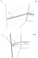
- Fig. 7 there is shown part of a stopping arrangement, to stop the shower floor.
- an example stopping feature 50' (which is part of the stopping arrangement, to stop the shower floor).
- the example stopping feature 50' is provided by way of (and the example stopping arrangement therefore comprises) a bracket feature(s)).
- the shower may simply comprise a protruding portion(s) that stops the shower floor in position, in the shower use mode.
- Stopping arrangements of varying type, shape and design may be provided, not limited to the example(s) shown).
- the stopping feature (and/or stopping arrangement) is angled (and is sloping). In the example, fluid (and thus water from the shower) can drain down the stopping feature).
- the stopping feature is angled slightly downward, toward an example catching area 26.
- the catching area is provided by way of (and therefore comprises) a gutter.
- the stopping arrangement being sloping may lead to water draining from the shower floor, (preferably into a catching area).
- the or any flow arrangement may feasibly comprise a channel arrangement).
- other embodiments may be provided, for example, where the stopping feature is angled slightly downward, toward a flow arrangement.
- Fig. 8 the example shower floor 14 is shown held in position, (in the shower use mode), by the example stopping arrangement.
- a portion of the shower floor has descended into the example bracket element.
- this is just one example of how a stopping feature may stop the shower floor, and many other embodiments of how this is done may be provided, not limited to the example of Fig. 8 ).
- water from the shower that falls onto the shower floor flows toward (and into) the example catching area 26.
- the stopping arrangement could be horizontal (or any angle), and the shower floor could simply then have a portion or a whole of a surface that is sloped, so that water flows from the shower floor, to the catching area).
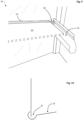
- Fig. 9 the same (or a similar) embodiment is shown, as to that shown in Fig. 7 and Fig. 8 .
- the shower floor is shown/illustrated cut off (denoted by the dashed lines in Fig. 9 ), so that the catching area 26 can be seen better. It can be seen how, in the example, water would be able to flow off the shower floor 14, and into the catching area 26.
- the shower floor is preferably watertight to a portion or a whole of the perimeter of the shower.
- this may be achieved in many ways.
- this is achieved by way of a seal arrangement.
- an example seal element 52' is shown in Fig. 8 and Fig. 9 .
- a portion or a whole of the seal element is deformable.
- it may, for example, be made of rubber, for example, and/or plastic, and/or any deformable material(s).
- a feature(s) eg a ledge, for example
- the shower floor in the shower use mode, may then engage with this 'ledge', and may do so, for example, in a way that achieves water-tightness with this ledge (in the example), distant (ie away from) the edge of the perimeter, (ie further in to the shower than in the example of Fig. 8 ).
- the shower floor is watertight to a portion or a whole of a perimeter of the shower.
- the shower floor is watertight to a portion or a whole of a 'side' of the shower. (This includes within its scope either of the examples given- ie wherein water-tightness is achieved right at the edge of the shower, or even if it is achieved (eg via a 'ledge', as in the example given) further inwards).
- the shower floor is watertight to a portion or a whole of a side of the shower).
- the term 'water-tight to a portion or a whole of a side of the shower' is considered to include within its scope the term 'water-tight to a portion or a whole of a perimeter of the shower').
- a basic view is shown, to denote that it is feasible the or any catching area may be provided, as part of the shower floor 14.
- the shower floor can rotate upwards (towards, for example, back wall/side 21, which is what the upward line in the drawing may, or may not, represent).
- the shower floor can rotate to the shower use position that it is shown in in Fig. 10 .
- the catching area 26 is shown.
- the catching area may be permanently attached to the shower floor, may be removably attachable, or may be formed as one piece with a portion or a whole of the shower floor.
- Figs. 7, 8 and 9 only one side of the example combined shower and toilet arrangement 10 is shown. However, it will be apparent that preferably similar (or the same) features are provided for the other side of the example combined shower and toilet arrangement 10. Thus a stopping feature may also be provided on the other side, (as part of the/a stopping arrangement). Thus there may also be a seal element on the other side. In the example, the shower floor does comprise another seal element on the other side, (not shown in the Figure).
- such feature(s) may also be provided at a front side of the shower and toilet arrangement 10.
- the shower floor may also be watertight to a portion or a whole of the door. (As stated, and made clear, this may be achieved in many ways, including, but not limited to, the example feature(s) as shown in Figs. 7 to 9 ).
- the door may, for example, comprise a stopping feature, to stop the shower floor, in the shower use mode.
- the watertight arrangement may mean the combined shower and toilet arrangement is watertight between the shower floor and the door, in the shower use mode.
- the example stopping arrangement is shown comprising separate (more than one) stopping features, it is feasible just one stopping feature is provided, which nevertheless stops the shower floor, in the shower use mode.
- the one stopping feature may, feasibly, circumnavigate a whole of the perimeter of the shower. (However, it will be apparent that embodiments may be provided where (whether there is on, or more, stopping features) the stopping arrangement does not go around the whole of the perimeter, and yet is able to carry out its function, to stop the shower floor).
- the or any side (or any portion at all) of the shower may be flush to the shower floor 14, in shower use mode, in order to assure watertightness.
- the or any side of the shower may be provided by way of side panel(s), (which may be made of glass, for example)).
- side panel(s) which may be made of glass, for example
- feature(s) may be provided to/with the shower floor (and/or even the or any side(s) of the shower), (eg as shown in Fig. 8 , for example).
- an example support arrangement (such as the example of Fig. 8 , for example,), whilst not 'engaging with the ground surface' in such an obvious (or 'direct') way as the example of Fig. 1 , for example, could be argued to (and may well) 'indirectly' engage the ground surface, by virtue of being connected to another feature(s) of the combined shower and toilet arrangement, (such as a side(s) of the shower, for example, which itself engages with the ground surface, or a further support feature(s) (such as a corner strut(s)/feature(s), for example, which itself engages with the ground surface).
- the or any support arrangement engages with the ground surface, directly or indirectly.
- a support arrangement could in no way (either directly or indirectly) engage with the ground surface.
- it could engage with the/a ceiling, for example, rather than the ground surface, (although this may be cumbersome and undesirable, from a build and/or function point of view).
- Fig. 1 (and Fig 3 , for example) is an example of wherein there is a support arrangement that, in the non-use mode (of the shower floor), does not engage the ground surface, and, in the shower user mode, does engage with the ground surface (to support the shower floor).
- a support arrangement to support the shower floor in the shower use mode wherein, the support arrangement, in the shower use mode, engages with a ground surface, to support the shower floor; and in the non-use mode, does not engage with the ground surface).
- such support arrangements are connected to the shower floor.
- they are connected to the shower floor, and move with the shower floor, as the shower floor moves from the shower use mode to the non-use mode (and vice versa).
- Such support arrangements ie that, in the shower use mode, engage with a ground surface, to support the shower floor; and in the non-use mode, do not engage with the ground surface
- support arrangements that engage with the ground surface (both in the non-use mode, and in the shower use mode), and which are not connected to the shower floor.
- a support arrangement eg support strut(s) or the like
- a protruding strut(s) may extend from the ground surface, and be usable to support the shower floor in the shower use mode. It may then simply remain in the same position in the non-use mode, (or may, for example, be in some way movable (whilst remaining connected/attached to the ground surface), in the non-use mode).
- a support arrangement eg support strut(s) or the like
- a protruding strut(s) may extend from the ground surface, and be usable to support the shower floor in the shower use mode. It may then simply remain in the same position in the non-use mode, (or may, for example, be in some way movable (whilst remaining connected/attached to the ground surface), in the non-use mode).
- Fig. 8 The example shown in Fig. 8 , therefore (if what is shown is an example of a support arrangement), is not an example of a support arrangement which, in the shower use mode, 'directly' engages with a ground surface, to support the shower floor, (because those features do not, in the example, engage with a ground surface (eg a bathroom floor). It should also be stated that such features may be provided, along with a support arrangement for the shower floor, which, in the shower use mode, engages with a ground surface (directly), to support the shower floor. (Thus the example stopping arrangement shown in Figs.
- a support arrangement for the shower floor which, in the shower use mode, engages (directly) with a ground surface, to support the shower floor, (such as the example support arrangement 28, for example, of the embodiment of Fig. 1 , which, in the shower use mode, engages directly with a ground surface, to support the shower floor).
- a support arrangement for the shower floor which, in the shower use mode, engages (directly) with a ground surface, to support the shower floor
- the example support arrangement 28 for example, of the embodiment of Fig. 1
- the shower use mode engages directly with a ground surface, to support the shower floor.
- any other arrangement(s), eg cantilever/limited rotation, or any support arrangement(s) at all, eg slide-out/pull-out feature(s), etc, or any other support arrangement(s), for example.
- the or any support arrangement could be provided anywhere in any way (eg jutting out element(s) (which would be an example of a protruding element(s)) from side (or any area) of the shower. Thus a huge array of possible embodiments are possible).
- the shower floor in such embodiments, could feasibly 'hover' (ie 'be') above the arrangement (eg above the example arrangement shown in Figs. 7 to 9 ).
- cantilever or any limited rotation mechanism
- cantilever may be provided, and may be a means for the shower floor to be 'supported' or 'stopped' in the shower use position.
- such mechanisms may be likely to 'fail' if not used in conjunction with other support feature(s). Therefore, preferably, if a cantilever (or any limited rotation mechanism) is used, a support arrangement(s), (to support the shower floor in the shower use mode) is also provided.
- the combined shower and toilet arrangement may be removable/transportable as a unit.
- all (any or all of the features) that is shown in the example of Fig. 1 is transportable (whether all kept together as shown, or feasibly with parts being removably attachable (and/or disassemble-able) from each other), so that it could be placed, for example, in another location.
- the combined shower and toilet arrangement can be provided built-in as part of a room/location (eg with any or all of the sides of the combined shower and toilet arrangement being provided by wall(s) of a room, for example), it is feasible (and in fact may be preferable) that all parts (eg in the example of Fig. 1 ) are provided as a unit.
- the combined shower and toilet arrangement may be added to any location and/or room that it can fit into. (It is feasible, in a situation where water plumbing and/or feature(s) are already present, that the other features of the combined shower and toilet arrangement can be 'added' to the water system feature(s) already present. This may be useful, for providing the combined shower and toilet arrangement to bathrooms that already have water plumbing/evacuation in place). It may be possible, (as stated), to disassemble a part or parts of the combined shower and toilet arrangement. This may allow for it to be easily taken to a location for it to be provided in, (eg easy to take it through a door of a bathroom, (or any room), in parts), and then build it, in that location. As stated, it also may allow for the combined shower and toilet arrangement to be re-located to another location. It may, or may not, come with a floor 101. It may, or may not, come with a back wall 20.
- the combined shower and toilet arrangement may be transportable, (whether that be as an assembled unit, or as disassembled parts), (and may comprise an enclosing arrangement that is transportable as part of the combined shower and toilet arrangement).
- the combined shower and toilet arrangement may be transportable, assembled together.
- a portion or a whole of the combined shower and toilet arrangement may be transportable (as a unit), assembled together. It is feasible, in some embodiments that a whole of the combined shower and toilet arrangement is transportable (as a unit), assembled together.
- a unit could be, for example, used for festivals, etc (or any other use).
- the unit may be transported (eg by lorry, or any other way/means), used for a festival, for example, and then removed (and transported elsewhere, for example), potentially for use at another festival and/or event and/or place.
- the door may be advanced, compared to where the sides of the combined shower and toilet arrangement end.
- An example of this is shown in Fig. 11 , by way of example. (Features such as the toilet, the shower fluid outputting arrangement, etc are not shown in Fig. 11 , in order to focus clearly on the example door features shown).
- the door comprises portions 62.
- portions 62" and 62′′′ are therefore, when the door is in a closed position, advanced, compared to where the sides of the combined shower and toilet arrangement end. (In the example, the sides of the combined shower and toilet arrangement end generally around where hinges 58 are).
- a curtain may be provided, (eg with a rail, et al., or ay way of proving a curtain), which could function, (and be provided) similarly to a door, (or at least to prevent water from escaping and/or provide privacy).
- the or any curtain may be afforded any feature(s) afforded to the or any door in the present application- eg it may be 'advanced', compared to where the sides of the combined shower and toilet arrangement end. (As stated, (and shown in an example embodiment of Fig. 11 , for example), this may help water not escape from the shower, in use).
- a curtain rail may be provided in an advanced position, allowing the curtain to be opened and closed, when needed, in an advanced position.
- a curtain rail may be provided in any position, of course.
- embodiments may be provided where the shower can be enclosed on all sides, via use (at least on one side) of a curtain.
- a curtain could be used to enclose the shower on more than one (or even all) sides.
- many shower curtains go around a corner of the shower, and enclose the shower on two sides.
- a curtain could even be used to enclose the shower on all sides).
- the combined shower and toilet arrangement comprises a door, to facilitate enclosing the shower on all sides).
- an example structure 25 there is shown an example structure 25.
- the example could be described as a 'chassis').
- the example structure is provided by way of example only. (Various different designs/shapes may be provided).
- the structure comprises one or more (and in the example comprises a plurality) of upward struts.
- the example is shown working as a frame.
- the structure supports one or more feature(s) of the combined shower and toilet arrangement.
- the structure supports any of (and in the example supports all of): the toilet; an example unit 27 (which preferably comprises a tank), (broadly speaking, a portion or a whole of the or any flushing system); the shower floor; a catching area 26. (And may support any other feature(s)). Thus it may support any feature, or combination of features.
- the example of Fig. 5 is an example of a suspended toilet. (If the toilet is not suspended (eg as in Fig. 6 , for example), there may or may not be provided a structure 25)).
- the example structure is provided by way of example only, and may different types of composition and/or shape, etc may be provided.
- the example structure 25 comprises a plurality of struts (vertical and horizontal). However, this is provided by way of example only).
- unit 27 comprises a tank.
- the tank is a cistern).
- the tank in the example, stores water).
- the combined shower and toilet arrangement can be provided, by way of 'addition', to a pre-existing toilet or shower.
- the toilet and the shower are constructed/fitted together (as part of the same build), (rather than adding one or the other to a pre-existing toilet or shower).
- any or all of the features provided may be provided as a unit, (rather than features like the example wall 20 and example floor 101 being part of the or a room the combined shower and toilet arrangement is provided for/in).
- the example floor 101 in Fig. 1 , for example
- the unit may transportable.
- the unit may feasibly be provided as an assembly.
- one or more parts may be de-assembled, for transportation.
- the combined shower and toilet arrangement (preferably provided as a unit), may be provided for festivals (eg outdoor festivals). In such a case, the combined shower and toilet arrangement is preferably enclosed on all sides. (This may be useful/important for privacy, and/or temperature, etc).
- any or all of the features may be provided as part of an assembly.
- any or all of the features may be provided as part of a unit, (which may be transportable).
- a portion or a whole of the shower floor is sloped, to facilitate directing water from the shower floor, and wherein, due to the portion or the whole of the shower floor being sloped, water from the shower floor is directed at least one of: off a side of the shower floor; through an aperture arrangement in the shower floor, wherein the aperture arrangement is not positioned above the receiving area of the toilet.
- water from the shower floor is directed off a side of the shower floor.
- a side of the shower floor As shown well in Fig. 6 , for example, where water is directed off a side of the shower floor. In the example, water is directed off a back side of the shower floor, but in other embodiments, for example, water may be directed off any side(s) of the shower floor, due to a portion or a whole of the shower floor being sloped).
- an aperture arrangement in the shower floor for water to travel through, for water to be directed from the shower floor, (and not travel through the receiving area of the toilet)).
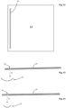
- Fig. 12 an example is shown of an example shower floor.
- the aperture arrangement comprises at least one aperture (and the example shown has only one aperture).
- the aperture arrangement may comprise a plurality of apertures for water to travel through.
- the example shown is an example of an aperture arrangement, that is not positioned above the receiving area of the toilet).
- Arrow 77 denotes possible trajectory of water that has travelled through the example aperture arrangement 70 in the shower floor.
- FIG. 13 A cross-section of the same (or a similar) embodiment of a shower floor is shown in Fig. 13 .
- the receiving area of the toilet and the toilet itself are not shown in the Figure, simply to focus on the relevant feature(s), (eg the example aperture arrangement 70)).
- the example aperture arrangement is not positioned above the receiving area of the toilet.
- this is again an example of water not being directed through the receiving area of the toilet.
- water that travels through the example aperture arrangement 70 goes into an example catching area 26. Water is directed into a catching area.
- a portion or a whole of the catching area is within a perimeter of the shower floor, (under the shower floor).
- a whole of the catching area may be within a perimeter of the shower floor, (under the shower floor). (This may depend on placement of the aperture arrangement).
- a whole of the catching area is shown in the example of Fig. 14 ).
- embodiments may be provided wherein a portion of the (or any) catching area is within the perimeter of the shower floor, (under the shower floor). However, it should also be stated that embodiments may be provided wherein a whole of the (or any) catching area is outside of the perimeter of the shower floor. (An example of this is best shown in the example of Fig. 10 , for example, where it can be seen that not even a portion of the example catching area is within the perimeter of the shower floor, (under the shower floor)). In this example, water is directed off a side(s) of the shower floor, into the catching area).
- Fig. 13 and Fig. 14 basic representation is shown.
- the example catching areas are shown in basic fashion.
- Other feature(s), such as the toilet, and channel(s) etc that water may, or may not, be directed into and/or through) are not shown, in order to provide clarity as to what is shown/depicted.
- water may, (or may not), flow through other channel(s) etc
- the examples of Figs. 12 to 14 are not limited only to comprising the features shown, and may draw upon (and be afforded) any other feature(s)/disclosure of the present application, (which will be apparent).
- embodiments may be provided wherein there is not provided a catching area.
- a catching area For example, (taken by way of example only), due to sloping of the portion or the whole of the shower floor, water may be directed from the shower floor (into the water system of the toilet, for example), without there being a catching area.
- water may be directed from the shower floor (into the water system of the toilet, for example), without there being a catching area.
- water may be directed from the shower floor (into the water system of the toilet, for example), without there being a catching area.
- a catching area (the catching area not being the pan of the toilet).
- a portion or a whole of the catching area may be within the perimeter of the shower floor, (under the shower floor)).
- a portion or a whole of the catching area may be outside the perimeter of the shower floor, (under the shower floor).
- a portion or a whole of the shower floor is sloped, to facilitate directing water from the shower floor, and wherein, due to the portion or the whole of the shower floor being sloped, water from the shower floor is directed at least one of: off a side of the shower floor; through an aperture arrangement in the shower floor, wherein the aperture arrangement is not positioned above the receiving area of the toilet.
- Both examples are examples (ie the example (eg in Fig. 6 ) of water being directed off a side(s) of the shower floor, (due to sloping of a portion or a whole of the shower floor)), and the example (eg as shown in the examples of Figs. 12 to 14 ) of there being an aperture arrangement in the shower floor, (the aperture arrangement not being positioned above the receiving area of the toilet), through which water is directed, (due to sloping of a portion or a whole of the shower floor), are examples of wherein water from the shower, due to sloping of a portion or a whole of the shower floor, is directed from the shower floor, (and does not travel through the receiving area of the toilet).
- a portion or a whole of the (or any) stopping arrangement may be sloped. (This may facilitate drainage of water). (As alluded to, a portion or a whole of the (or any) stopping arrangement being sloped may facilitate stopping the shower floor in a sloped position). It should also be stated, a stopping arrangement that is not sloped may nevertheless facilitate the shower floor being stopped in a position wherein a portion or a whole of the shower floor is sloped, (to facilitate directing water from the shower floor). For example, an embodiment of a stopping arrangement may be provided wherein the shower floor is stopped in a sloping position, (irrespective of whether a portion or a whole of the stopping arrangement is sloped).
- a feature(s) that protrudes inwardly at a side(s) of the shower eg a knob(s), bar(s), etc),_(a bar(s) being an example of a feature(s) that travels from one side of the shower (and which may perhaps travel to another side of the shower, for example)), a bar(s) being just one example of a feature(s) that travels from one side of the shower (and which may perhaps travel to another side of the shower, for example), such feature(s)/example(s) not limited to being/comprising a bar(s)), (or any relevant stopping feature(s) at all- for example, it has been alluded to that a support arrangement that engages a ground surface, in the shower use mode, for example, may act as a stopping arrangement)), stops the shower floor (wherein the shower floor is rotatably movable from the non-use position to the shower use position), at a position before it has rotate
- feature(s) may be provided that are moved (in order to protrude inwardly at a side(s) of the shower, and stop the shower floor in the shower use position).
- a bar(s) or any feature(s) may be used, which needs to be moved, (eg pulled out, rotated, placed (ie may be manually placed by the user, eg if it is stored or placed aside when the combined toilet and shower arrangement is in the toilet use mode), attached, etc), to thus stop the shower floor in the shower use position.
- the shower floor may be horizontal/flat (eg on a portion or a whole of its underside), but may be shaped in such a way (eg with a portion or a whole of its top surface being sloped, to facilitate drainage), to facilitate drainage.
- embodiments may be provided wherein there is a stopping arrangement that stops the shower floor in a flat/horizontal position, and yet nonetheless, wherein a portion or a whole of the shower floor is sloped, (to facilitate directing water from the shower floor).
- stopping feature(s) of a wide variety of shapes and/or sizes may be provided, (as has already been alluded to).
- stopping arrangements may be provided, in varying embodiments).
- embodiments wherein the shower floor is stopped in a flat/horizontal position, (and where a portion or a whole of the shower floor is sloped (to facilitate directing water from the shower floor)), may benefit from (and/or be afforded) disclosure relating to (ie may comprise) an aperture arrangement that is not positioned above the receiving area of the toilet.
- an embodiment(s) may be provided, for example, wherein a portion or a whole of the shower floor is sloped (to facilitate directing water from the shower floor), a portion or a whole of the underside of the shower floor is flat/horizontal in the shower use position, and there is an aperture arrangement in the shower floor, wherein the aperture arrangement is not positioned above the receiving area of the toilet).
- the combined shower and toilet arrangement comprises a stopping arrangement, to stop the shower floor in the shower use position.
- the stopping arrangement protrudes inwardly at a side of the shower, and the shower floor engages it, to stop the shower floor in the shower use position.
- the stopping arrangement (and any relevant stopping feature(s) of the stopping arrangement) may be provided at any side(s) of the shower, (eg left side and/or right side, and/or front (side), etc).
- the stopping arrangement protrudes inwardly at opposing sides (of the shower). (This has been alluded to).
- the stopping arrangement protrudes inwardly at a left side and a right side (of the shower).
- the stopping arrangement may be provided by way of (and thus may, broadly speaking, comprise) a ledge(s), that extends/protrudes from the side of the shower.
- a ledge(s) that extends/protrudes from the side of the shower.
- An example of this, for example, would be if there is a step(s) in a side of the shower.
- the side(s) of the shower may be provided by way of a wall(s), and/or may not (eg via there being a screen(s), etc)).
- An example of a step(s), for example, (provided by way of example only), would be if there is a wall(s), (which is a side of the shower), and wherein there is step in the wall(s).
- the shower floor may be able to rest on the step(s), thus stopping the shower floor (in the shower use position).
- a stopping arrangement that protrudes inwardly at a side of the shower, and which the shower floor engages, to stop the shower floor in the shower use position.
- a ledge at opposing sides of the shower.
- a ledge at a left side and a right side (of the shower)
- a stopping feature(s) that protrudes inwardly at a side of the shower, and which the shower floor engages, to stop the shower floor in the shower use position may be provided, (all being within the scope of a stopping arrangement that protrudes inwardly at a side of the shower, and which the shower floor engages, to stop the shower floor in the shower use position).
- the (or any) stopping arrangement that protrudes inwardly at a side of the shower, (and which the shower floor engages, to stop the shower floor in the shower use position) may comprise any feature(s) that protrudes inwardly at a side of the shower, (and which the shower floor engages, to stop the shower floor in the shower use position).
- the term 'step' in the side(s), (eg wall(s)), here does not refer to a step that is intended, (at least not primarily), 'for stepping on' by a user. It is a term used to refer to structural shape of the side(s), (eg wall(s)). (With reference to a step(s), at the point from which the side(s) protrude inwardly, (to form the step(s)), the side(s) tend to then continue (to be protruding) to the bottom of the side(s) (eg wall(s)), (eg going downward, straight, or substantially straight).
- a step(s) protrudes inwardly, but then, lower down the side(s), (eg wall(s)), does not protrude as much (eg is recessed, for example) as it does higher up the side(s), (eg wall(s)). (It is also even feasible that the step(s) may protrude further inwardly, lower down the side(s), (eg wall(s)))).
- the (or any) toilet paper holder may be provided on the shower floor, (ie not limited to being provided on the underside of the shower floor).
- the (or any) user means 36 to activate flushing of the toilet.
- the (or any) user means, to activate flushing of the toilet may be provided on the shower floor, (ie not limited to being provided on the underside of the shower floor).
- FIG. 15 an example is shown of a toilet roll holder that is (at least partially) on a side facing portion 80 of the shower floor.
- a toilet roll holder is attached at a side facing portion of the example shower floor.
- the example toilet roll holder is attached to an example side facing surface of the shower floor.
- the toilet roll holder may be attached in any way (eg via screw(s), clip(s), adhesive(s), etc, or any other way).
- the example toilet roll holder is attached, in the example, at point 82.
- the (or any) toilet paper holder is not limited to being a toilet roll holder).
- the toilet paper holder (and/or the user means, to activate flushing of the toilet), may be provided on the top surface of the shower floor.
- this may be extremely unwise and/or problematic, as it may make it very likely (or guaranteed) that water (from the shower) will go onto the toilet roll holder (and/or the user means, to activate flushing of the toilet), when the shower is being used.
- the toilet paper holder (and/or the user means, to activate flushing of the toilet) may also be stepped on by the user, (when the user uses the shower) if either (or both) are provided on the top surface of the shower floor.
- the toilet roll holder (and/or the user means, to activate flushing of the toilet) being provided on the top surface of the shower floor may cause problems, in the shower use mode. Therefore preferably the toilet paper holder (and/or the user means, to activate flushing of the toilet) are provided on the shower floor, but not on the top surface of the shower floor.
- Fig. 16 there is shown another example in Fig. 16 .
- Fig. 16 there is an example overhang 84'.
- the overhang comprises (and/or creates) example surface 86' and example surface 88'.
- the toilet roll holder is attached to example surface 88').
- example surface 88 is a side facing surface.
- that surface is considered to be part of the underside of the shower floor.
- Fig. 16 is an example of the toilet paper holder being provided on the underside of the shower floor).
- the (or any) overhang may be useful for resting on a stopping arrangement, to stop the shower floor in the shower user position).
- example surface 86' may engage with a stopping arrangement, to stop the shower floor in the shower user position).
- the shower floor has an overhang at more than one side of the shower floor. In other examples, there may be an overhang at one side of the shower floor, for example).
- one or more of the sides of the shower floor may overhang.
- Fig. 17 the example user means is shown provided on a side facing portion of the shower floor, (similarly to the example toilet roll holder in Fig. 15 ).
- Fig. 18 there is shown an example overhang 84" (similar to the example of Fig. 16 with the toilet roll holder).
- the overhang comprises (and/or creates) example surface 86" and example surface 88".
- the example user means 36 is on example surface 88".
- example surface 88" is a side facing surface.
- that surface is considered to be part of the underside of the shower floor.
- Fig. 16 is an example of the user means 36, to activate flushing of the toilet, being provided on the underside of the shower floor.
- the (or any) overhang may be useful for resting on a stopping arrangement, to stop the shower floor in the shower user position).
- the user means is depicted as a protruding feature.
- the user means may protrude is such a way (in various embodiments), it should be stated, what is shown is shown by way of example only, (and to provide clarity as to what is being shown/disclosed).
- the (or any) user means, to activate flushing of the toilet may not protrude at all.
- the user means may be touchless.
- a touchless user means may, or may not, protrude).
- the fact that the user means appears to protrude suggests that it is an embodiment which requires touching (eg comprising a button, for example).
- the user means may be a touchless user means.
- toilet paper holder and/or the user means, to activate flushing of the toilet
- the toilet paper holder and/or user means, to activate flushing of the toilet
- the toilet paper holder may then also be partially on the top surface, or partially on the underside of the shower floor, for example.
- examples may be provided wherein the toilet paper holder (and/or user means, to activate flushing of the toilet) are partially on an underside of the shower floor.
- the toilet paper holder (and/or user means) may then also be partially on a side facing surface of the shower floor, for example).
- 'side facing' is not limited to the left and right side of the shower floor. For example, it could be at the front side of the shower floor, for example. Thus, rather than the term 'side facing' (and 'side facing portion(s)'), the term 'outward facing' (and 'outward facing portion(s)') may also be used, (and is appropriate).
- Fig. 19 for example, an example embodiment is shown, (now showing an example embodiment of the shower floor in the toilet use position).
- an example user means 36 to activate flushing of the toilet.
- the example user means is shown provided on what, when the shower floor is in the shower use position, is a front 'outward facing' portion of the shower floor.
- the user means, in the example, is nevertheless well accessible to the user, to activate flushing.
- the large arcing double-arrowed dashed line in Fig. 19 denotes, as the shower floor is rotatably movable, a rotational arc (arc of rotation) as the shower floor rotates between the toilet use and shower use positions)).
- Figs. 15 and 16 show only a toilet paper holder (not a user means, to activate flushing of the toilet), and Figs. 17 and 18 show only a user means, to activate flushing of the toilet, (not a toilet paper holder), it should be stated, (as will be clear from the disclosure of the present application) that various permutations/combinations are possible.
- both the user means and the toilet paper holder may be provided in such positions/locations, (eg on one, (or opposing and/or other), side facing surface(s)) of the shower floor.
- one, or the other may be provided on the shower floor, and the other may, for example, be provided elsewhere (at any other location/place, not limited to being on the shower floor).
- the toilet paper holder and/or use means for activating flushing the toilet
- one (or both) may be provided, not at all limited to being provided on the shower floor. (Thus the toilet paper holder and/or user means, to activate flushing the toilet, may be provided anywhere, (not limited to being provided on the shower floor))).
- a toilet paper holder preferably there is provided on the shower floor at least one of: a toilet paper holder; a user means, to activate flushing of the toilet.
- a toilet paper holder Preferably both the toilet paper holder and the user means to activate flushing of the toilet are provided on the shower floor.
- the shower floor is rotatably movable from the non-use position to the shower use position, and from the shower use position to the non-use position, rotatably movable from behind the receiving area of the toilet; wherein rotation of the shower floor is configured so that a whole of the receiving area of the toilet is within a circular trajectory of an arc of rotation of the shower floor as it rotates from the non-use position to the shower use position, the whole of the receiving area of the toilet thus being under the shower floor when the shower floor is in the shower use position. Examples of this are shown in the drawings. However, a best depiction of this, (in terms of an understanding of this), is shown in Fig. 20 (and, to some extent, Fig. 19 ). To explain this, Fig.
- FIG. 20 the shower floor is shown in the non-use position.
- the shower floor is shown, generally having been rotated into a non-use position in the example, (and generally at approximately 90 degrees, (ie pointing directly upwards, in the example, for simplicity and clarity here, although, as has been stated, embodiments may be provided wherein the shower floor extends beyond vertical)).
- Added is also a representation of the shower floor, (shown in dashed lines), to show the shower floor in the shower use position.
- the curved double arrowed lines between the shower floor in the non-use position and the shower use position denote the 'rotational arc' (ie arc of rotation) of the shower floor, as it moves, in the example, from the non-use position to the shower use position, (and from the shower use position to the non-use position).
- the curved double arrowed lines in Fig. 20 (between the shower use position and the non-use position), show the arc of rotation of the shower floor.
- the shower floor was able to rotate a whole 360 degree rotation, that would be the 'circular trajectory' of the arc of rotation of the shower floor.
- a side view of a clear example/depiction is shown, of an embodiment wherein the shower floor is rotatably movable from the non-use position to the shower use position, and from the shower use position to the non-use position, and wherein, throughout rotation of the shower floor from the non-use position to the shower use position, and from the shower use position to the non-use position, from a side view, not more than half of the shower floor is able to extend past a furthest point of the receiving area away from an axis of rotation about which the shower floor rotates.
- Dashed line A1 defines the furthest most point of the shower floor, (away from an axis of rotation about which the shower floor rotates), (ie to where the shower floor extends, in the example).
- Dashed line A2 defines the furthest point of the receiving area away from the axis of rotation about which the shower floor rotates. (Thus, preferably, not more than half of the shower floor extends past a furthest point of the receiving area, (from a side view), away from an axis of rotation about which the shower floor rotates). (This is preferably also the case in embodiments, not limited to being rotatably movable, (ie that not more than half of the length of the shower floor (from a similar side view, for example) extends past the receiving area).
- FIG. 1 also shows an example embodiment of wherein at a lowest point of rotation, for example, more than half of the shower floor, from a side view, does not extend past the furthest point of the receiving area away from the axis of rotation about which the shower floor rotates, (although it is relatively close to this not being the case, (ie relatively close to not being within this scope), compared to some of the other embodiments shown).
- not more than half of the shower floor is able to extend past a furthest point of the receiving area away from an axis of rotation about which the shower floor rotates, (ie not more than half of the shower floor is able to extend past dashed line A2)).
- Fig. 20 only a basic representation of the toilet is shown. However, it should be stated, the toilet may be afforded any feature(s)/disclosure relating to the or any toilet in the present application, and it will be apparent that the example toilet is represented in basic fashion. (There may be pipe(s)/piping, etc, for example. Such feature(s) are not shown, simply due to the fact that Fig. 20 is a basic representation, and is intended to focus more on position of the shower floor, for example)).
- the example shower floor is also shown slightly sloped, in the shower use position. Thus it is an example of a portion or a whole of the shower floor being sloped, to facilitate directing water from the shower floor).
- an embodiment may be provided wherein a whole of the receiving area of the toilet is within a circular trajectory of the arc of rotation of the shower floor, (as it rotates from the non-use position to the shower use position), but wherein, at the lowest point of rotation of the shower floor, more than half of the shower floor, from a side view, extends beyond the furthest point of the receiving area of the toilet away from the axis of rotation about which the shower floor rotates.
- a lid and/or toilet seat of the toilet may not be shown.
- a toilet seat Preferably, (whether shown or not), there is provided a toilet seat.
- a lid for the toilet Preferably both are provided).
- the toilet comprises a toilet seat.
- An example(s) is shown, in various drawings, of a rotatable toilet seat, for example.
- a rotatable toilet seat for example.
- an example rotatable toilet seat is shown up, (rotated up).
- Fig. 2 for example, an example rotatable toilet seat is shown down. (These are shown by way of example only).
- a lid for the toilet preferably there is provided a lid for the toilet.
- an example(s) is shown of a rotatable toilet lid.
- An example rotatable toilet lid is shown, up, in the example of Fig. 5 , for example.
- An example rotatable lid is shown, down, in Fig. 1 , for example.
- the shower floor may extend beyond vertical. (This can allow it to maintain its position due to gravity).
- the combined shower and toilet arrangement may comprise a holding arrangement, to hold the shower floor in the non-use position.
- the holding arrangement may hold the shower floor to a back wall behind the toilet, in the toilet mode. (As stated, the shower floor may extend beyond vertical, in the toilet use mode, (and this can allow it to maintain its position due to gravity)).
- the combined shower and toilet arrangement comprises a flow arrangement, to direct water from the shower floor, into a water system of the toilet.
- the flow arrangement is configured to direct water from the shower floor, into a pan of the toilet.
- a catching area to catch water from the shower.
- a support arrangement to support the shower floor in the shower use mode.
- the combined shower and toilet arrangement may be transportable, assembled together.
- the combined shower and toilet arrangement may comprise a water tank, for the toilet.
- Water tanks are often used to store water).
- the water tank may be behind a wall, (and may thus not be within the shower).
- the toilet flush user means may feasibly be a mechanical user means, (such as a rotatable lever, for example, which initiates flushing), this may be fairly challenging to engineer, (taking into account the movement of the shower floor).
- a mechanical user means such as a rotatable lever, for example, which initiates flushing
- this feature(s) eg a chain, or any feature(s)
- this feature(s) either itself (or via being connected with and/or interacting with another feature(s)
- flushing the toilet flushing the toilet.
- the toilet flush user means 36 is an electronic user means. This is also plausible for an embodiment wherein the user means is provided on the shower floor.
- the user means may be wireless. If, however, there are wire(s), such wire(s) may be provided internally and/or externally to the shower floor. Thus such wire(s) may be directed towards any location/part(s)/feature(s), (even to a location/part(s)/feature(s) away from the shower floor), to facilitate the toilet flushing.
- Water from the shower floor may be directed into a flush channel of the toilet.
- An example of this is shown most visibly in the examples of Fig. 5 and Fig. 6 .
- an example flush channel 99 of the toilet (that water travels through, for flushing the toilet).
- the example channel 99 is also an example of a channel 24, through which water from the shower is directed).
- the example flush channel is a flush pipe, (which is an example of a flush channel).
- the example shown (in Fig. 5 and Fig. 6 , for example) is an example of wherein water from the shower floor is directed into a flush channel of the toilet). This may be achieved in various ways.
- an aperture(s), may be made in the (or any) flush channel of the toilet. (For example, this may be done forcibly). Thus an aperture(s) may be plumbed into the (or any) flush channel of the toilet).
- a similar (or same) method may be used, even if the combined shower and toilet arrangement is provided new, (as opposed to retrofitting a toilet, for example), (eg the (or any) flush channel may have an aperture(s), (eg hole(s)) forcibly made into it. (Broadly speaking, an aperture(s) may be plumbed into the (or any) flush channel of the toilet).
- the (or any) flush channel may be bespokely provided, (configured to receive water from the shower). (Thus it may be manufactured, (with relevant feature(s), to facilitate this). Thus the or any flush channel may be manufactured with an aperture(s), (eg hole(s)/opening(s), or any area(s) to receive water from the shower).
- the (or any) flush channel may be provided, with an aperture(s) in it, for example.
- Thius forcible plumbing may not be required). This may be done in various ways. For example, a plurality of different channel parts, (eg pipes, for example) may be provided.
- example channels in Fig. 5 and Fig. 6 may be different parts, (eg different pipes, for example).
- the flush channel may be provided with an aperture(s), (eg hole(s)), in it, and the example channel (which is above the example flush channel, in the examples of Fig. 5 and Fig. 6 ) may be a different part, (eg different pipe, in the example).
- the two may then be connected together, (eg via a fitting, or in any other way), so water can travel into the flush channel.
- example channels 24 in Fig. 5 and Fig. 6 could be provided as one part, (eg manufactured as one part). (Thus they may be bespokely manufactured as one part, for example).
- water from the shower is received by the flush channel of the toilet.
- the (or any) flush channel may receive water from the shower.
- the examples described (and shown) are examples of the (or any) flush channel receiving water from the shower).
- pipe(s) may be provided, as channel(s).
- a void that functions as a channel is considered to be within a scope of being a channel.
- the void functions as a channel, that is considered to be an example of a channel.
- some parts of toilets are often made of ceramic material(s), (eg porcelain, for example).
- a void is provided in such a part(s)/feature(s), (not limited at all to ceramics, but may be any part(s)/feature(s) and may be any material(s)), and the void functions as a channel, then that is considered to be within the scope of being a channel.
- a flush channel for example, could feasibly be provided by way of a void in a toilet part(s)/feature(s)).
- channel(s) may be provided by way of void(s).
- channels eg as shown in the example channels 24 of Fig. 5 and Fig. 6 , for example), are not provided by voids.
- the channel(s) are non-void channel(s).
- channel(s) that are void(s), and channel(s) that are non-void(s) may be provided).
- a portion or a whole of a flush channel of the toilet may be provided by way of an elongate void, for example).
- non-void channel(s) include, (but are not limited to), pipe(s), tube(s), etc).
- the shower floor is rotatably movable from the non-use position to the shower use position, (and from the shower use position to the non-use position). Examples are shown in the drawings wherein the shower floor is rotatably movable from behind the receiving area of the toilet.
- the shower floor being rotatably movable is not limited to the shower floor being rotatably movable from behind the receiving area of the toilet.
- the shower floor could be rotatably movable from a left side (or right side), for example. This is just one example, to therefore show that the shower floor being rotatably movable is not limited to the shower floor being rotatably movable from behind the receiving area of the toilet.
- a channel arrangement ie one or more channel(s)
- the or any channel arrangement is not limited to having to direct water from the shower into the water system of the toilet.
- the or any channel arrangement may or may not direct water from the shower into the water system of the toilet).
- a portion or a whole of the channel arrangement is lower than a portion or a whole of an underside of the shower floor in the shower use position, (ie, preferably, with reference to the shower floor in the shower use position, preferably a portion or a whole of the channel arrangement is lower than a portion or a whole of an underside of the shower floor).
- a portion or a whole of the channel arrangement is lower than a portion or a whole of an underside of the shower floor.
- a portion or a whole of the channel arrangement that is lower than a portion or a whole of an underside of the shower floor in the shower use position, and is within a perimeter of the shower floor, that is also an example of a portion or a whole of the channel arrangement being is lower than a portion or a whole of an underside of the shower floor in the shower use position.
- Embodiments may be provided wherein a portion of the channel arrangement is lower than a portion or a whole of the underside of the shower floor in the shower use position and is within a perimeter of the shower floor, and a portion of the channel arrangement is lower than a portion or a whole of the underside of the shower floor in the shower use position and is not within a perimeter of the shower floor. (The example of Fig. 6 most visibly shows an example of this).
- At least a portion of the shower floor does not extend further in distance away from an axis of rotation about which the shower floor rotates than half a distance of length of the shower floor, the length of the shower floor being defined as length of the shower floor along the shower floor, along an angle of rotation the shower floor is angled at to the axis of rotation.
- Line L1 shown in both orientations/positions in Fig. 20 ) is the length of the shower floor.
- the 'length' is here length of the shower floor along the shower floor, along an angle of rotation the shower floor is angled at to the axis of rotation.
- the angle of rotation the shower floor is angled at to the axis of rotation is denoted for both the example positions shown in the example of Fig. 20 .
- the angle of rotation the shower floor is angled to the axis of rotation is shown with dashed line R1b, (and is at approximately (or exactly) 90 degrees, in the example).
- dashed line R1a In the shower use position of the shower floor in the example, the angle of rotation the shower floor is angled to the axis of rotation is shown with dashed line R1a.
- the shower floor is slightly sloped.
- dashed line R1a the angle of rotation the shower floor is angled to the axis of rotation
- FIG. 20 Thin what is shown in the example of Fig. 20 is an example of wherein, throughout rotation of the shower floor from the non-use position to the shower use position, (and from the shower use position to the non-use position), from a side view with reference to rotation, at least a portion of the shower floor does not extend further in distance away from an axis of rotation about which the shower floor rotates than half a distance of length of the shower floor, the length of the shower floor being defined as length of the shower floor along the shower floor, along an angle of rotation the shower floor is angled at to the axis of rotation.
- the shower floor may be distanced from the axis of rotation, (ie that the shower floor may be able to extend away, for example, from the axis of rotation about which it rotates), (eg if there is provided a slide mechanism, or any other mechanism that distances the shower floor from the axis of rotation about which it rotates).
- the shower floor does in any way, at any point, distance itself from the axis of rotation about which it rotates, preferably it is not distanced further from the axis of rotation about which it rotates than half the length of the shower floor.
- the example of Fig. 20 is an example of wherein, throughout rotation of the shower floor from the non-use position to the shower use position, (and from the shower use position to the non-use position), at least a portion of the shower floor does not extend further in distance away from the axis of rotation about which the shower floor rotates than half a distance of length of the shower floor (made especially clear/apparent in light of use of the dashed lines HL1)).
- the shower floor throughout rotation from the non-use position to the shower use position, (and from the shower use position to the non-use position), does not distance itself at all. In other embodiments, it may distance itself slightly, but not by much, for example. (However, preferably, there is no distancing. Preferably there is no mechanism(s) that distances the shower floor from the axis of rotation about which it rotates).
- Dashed line X30a is shown.
- Dashed line X30a denotes a distance 30cm in distance higher than the axis of rotation about which the shower floor rotates.
- at least a portion of the shower floor is no more that 30cm higher than the axis of rotation about which the shower floor rotates. (The example of Fig. 20 is clearly an example of this).
- At least a portion of the shower floor is no more than 20cm higher than the axis of rotation about which the shower floor rotates. Still more preferably, preferably, throughout rotation of the shower floor from the non-use position to the shower use position, (and from the shower use position to the non-use position), at least a portion of the shower floor is no more than 10cm higher than the axis of rotation about which the shower floor rotates.
- At least a portion of the shower floor is no more than 5cm higher than the axis of rotation about which the shower floor rotates.
- the example of Fig. 20 is an example of all these, (ie no more than 30cm, no more than 20cm, no more than 10cm, and no more than 5cm).
- the receiving area may be, for example, 30cm from start to finish.
- the most left point of the receiving area, (and arrow RL1), (from the side view shown in the example of Fig. 20 ), could be considered to be the start of the receiving area, in the example, and the most right point of the receiving area, (and arrow RL1), (from the side view shown in the example of Fig. 20 ), could be considered to be the end of the receiving area, in the example.
- dashed line X30a also happens to denote/define a distance higher than the axis of rotation that is the distance of length of the receiving area (ie 30cm, in the example).
- at least a portion of the shower floor is no more than the length of the receiving area, (ie length of RL1) higher than the axis of rotation about which the shower floor rotates. (In other examples, length of RL1 may not be 30cm, (which will be apparent)).
- At least a portion of the shower floor is no more than the length of the receiving area, (ie length of RL1) higher than the axis of rotation about which the shower floor rotates, (whatever the length of RL1 may be for that embodiment).
- the axis of rotation (about which the shower floor rotates), in the example of Fig. 20 , would be/appear simply as a 'dot', (if denoted), (due to the side view shown). (It is generally pointed to with arrow and feature number 501). However, it would, in fact, be a line (that travels through the dot). It will be apparent what the axis of rotation (about which the shower floor rotates) is, in Fig. 20 , (especially in light of showing the shower floor both in an example shower use position, and in an example non-use position). However, it should be stated, the example provided is provided by way of example only, and it will be apparent that various differing embodiments may be provided, which may vary significantly from the example(s) shown).
- a portion or a whole of the catching area 26 is sloped. (This may help direct water).
- a portion or a whole of the catching area is curved. (This is an example of a portion or a whole of the catching area being sloped). However, such examples are not limited to being curved. For example, in Fig.
- FIG. 22 another example is shown of an example catching area, wherein a portion or a whole of the catching area is sloped.
- Thius portion(s) that are sloped may be straight, (rather than curved). In other embodiments wherein a portion or a whole of the catching area 26 is sloped, it should be stated it is feasible there is a combination of both straight (and curved) portion(s)).
- a basic (cross-sectional) representation is shown of the example in Fig. 22 .
- the example is shown from a front or back view.
- the examples are shown from a side view).
- the example catching area is v-shaped. The example is not curved.
- the catching area comprises an aperture arrangement (ie at least one aperture 199), through which water can travel.
- the catching area comprises an aperture arrangement, (and an example aperture can most visibly be seen in the examples of Fig. 5 and Fig. 22 ).
- the aperture arrangement may comprise a plurality of apertures.
- the aperture arrangement may comprise a plurality of apertures, or there may be only one aperture).
- an aperture arrangement may feasibly be provided with any embodiment of a catching area).
- the (or any) catching area may not comprise an aperture arrangement, (for water to travel through).
- a catching area may fill with water, and may be manually removed, (by a user, for example).
- the (or any) catching area does not comprise a aperture arrangement, (for water to travel through, and leave the catching area)).
- both a portion or a whole of the catching area is sloped, and the catching area comprises an aperture arrangement. It will be apparent that this can be extremely useful.
- the sloping (most clearly apparent in the design of the embodiment of Fig. 22 ), is able to direct water towards at least one aperture of the aperture arrangement. Thus the water can travel through, and leave the catching area.
- the portion or the whole of the catching area that is sloped may be sloped in one direction/orientation.
- the portion or the whole of the catching area that is sloped may be sloped in a plurality of directions/orientations.
- it is extremely apparent that (at least one aperture of) the aperture arrangement is located centrally (or very close to centrally).
- an aperture 199 that is substantially central.
- at least one aperture of the aperture arrangement is substantially central.
- an aperture arrangement that comprises a plurality of apertures may be provided that is substantially central.
- an aperture arrangement may be provided wherein at least one aperture is substantially central, (but not all apertures are substantially central)).
- the term 'substantially central' is a broad term, and may include being substantially central in any (or a plurality of) orientations), (eg from front to back of the catching area, (and/or from left to right of the catching area, for example).
- At least one aperture 199 of the aperture arrangement is positioned between two sloped portions of the catching area.
- at least one aperture of the aperture arrangement is positioned between two sloped portions of the catching area.
- at least one aperture 199 of the aperture arrangement is positioned between two opposingly sloped portions of the catching area.
- at least one aperture of the aperture arrangement is positioned between two sloped portions of the catching area, preferably at least one of the at least one aperture that is positioned between two sloped portions is positioned substantially centrally between the two clopped portions. An example of this is shown in both the example embodiment of Fig. 5 , and of Fig. 22 , for example).
- the aperture arrangement need not be central, (and it is not required that at least one aperture is positioned substantially centrally).
- the example aperture in the example of Fig. 6 is not substantially central.
- at least one aperture of the aperture arrangement is substantially central.
- the aperture arrangement (whether it comprises a plurality of apertures, or if there is just one aperture), is substantially central.
- the aperture arrangement comprises a plurality of apertures, preferably at least one aperture is substantially central. If there is only one aperture, preferably it is substantially central. (If the aperture arrangement comprises a plurality of apertures, they may all feasibly be substantially central).
- the aperture arrangement is in no way limited to being substantially central.
- an aperture arrangement may be provided wherein no aperture is substantially central.
- the (or any) aperture is not limited to being provided substantially centrally).
- the (or any) catching area may be sloped in more than two (or all) orientations/directions.
- the examples of Fig. 5 and Fig. 6 aside from being sloped (curved, in the example) from front and back (shown from the side view shown in Fig. 5 and Fig. 6 ), may also feasibly be sloped (eg curved, in the example), from left and/or right, (not visible from the view shown), or may not be sloped from left and/or right, for example).
- a preferred position/location of the example catching areas is shown in various of the Figures, (eg Fig. 5 and Fig. 6 ).
- the example catching area of Fig. 22 is positioned in a similar position to the example catching areas of Fig. 5 and Fig. 6 .
- the (or any) catching area is not at all limited to the positions shown, and may be provided at various positions /locations, in various different embodiments. This will be apparent, in light of the nature of the disclosure).
- the example catching area of Fig. 22 is positioned in a similar position to the example catching areas of Fig. 5 and Fig. 6 .
- the view shown of the example catching area of Fig. 22 is from a front, or back, view, (and thus is a view from a substantially perpendicular angle to the view of the examples of Fig. 5 and Fig. 6 ).
- the example of Fig. 22 is shown from an angle/view more akin to the angle/view of Fig. 4 , for example.
- it is preferably positioned in a similar position to the examples of Fig. 5, and Fig. 6 , (and preferably travels across (from left to right) in terms of reference to the orientation/view shown in the example of Fig. 4 ).
- water may, or may not, then travel through a channel(s).
- a channel(s) In the examples of Fig. 5 and Fig. 6 , it is apparent that water, having travelled through the example aperture of the aperture arrangement, travels through a substantially downward channel. (However, the or any channel(s) that the water travels through, (after travelling through at least one aperture of the aperture arrangement), are not limited to being substantially downward, and may be provided in differing shapes and/or directions and/or orientations, etc from the examples provided). In the examples, the water than travels into (and thus will travel through) an example flush channel 99 of the toilet.
- the example flush channel is provided by way of example only, and it will be apparent that the (or any) flush channel may be provided in differing shapes and/or directions and/or orientations, etc from the examples provided).
- the examples provided are provided by way of example only, and no undue limitation should be read onto them (and/or the disclosure), (eg that the features must all be provided, for example).
- the example substantially downward channel may not be provided, and the water may travel through at least one aperture of the aperture arrangement of the catching area, and directly into another channel (eg the (or any) flush channel, (or any channel(s) at all, (not limited to a flush channel, for example)).
- water that travels through at least one aperture of the aperture arrangement of the catching area may not travel through any channels after having travelled through the at least one aperture of the aperture arrangement.
- various embodiments may be provided and/or are possible/plausible).
- the (or any) catching area is self-enclosing, (in the sense that it does not rely on any other surface(s), for (ie to define) its area for water to travel into).
- the catching area is preferably self-enclosing.
- the example catching areas are self-enclosing at their example front and back, (from the side view shown). They are preferably both also self-enclosing, from left to right, (not visible from the angle/view shown in Fig. 5 and Fig. 6 )).
- the left and/or right of the catching area is not self-enclosing, (eg it may rely on a wall(s), (eg side wall(s)), or even a side(s) of the shower, (or any other surface(s), to define its area for water to travel into. (These would be examples of wherein the catching area is not self-enclosing). Thus it may rely upon other surface(s), to define its area for water to travel into. (The example surface(s) are provided by way of example only, and it may rely on any feature(s), feasibly, not limited to the examples provided). Similarly, the example catching area of Fig.
- the example catching area of Fig. 22 is preferably self-enclosing.
- the example catching area of Fig. 22 preferably does not rely on any other surface(s) to define it.
- the view shown in Fig. 22 does not show a front or back of the example catching area.
- the (or any) catching area is not self-enclosing/enclosed at a back (and/or front) of the catching area.
- the back of the catching area may, feasibly, rely on a back wall, for example, to define its area for water to travel into.
- the front, and/or back, of the (or any) catching area may rely on another surface(s), to define its area for water to travel into). (So the same may be the case for the left and/or right, for example). (Thus the (or any) catching area preferably is self-enclosing, (not relying on any other surface(s), to define its area for water to travel into). (But it should also be stated, it is feasible, in other embodiments, that the (or any) catching area may rely on another feature(s), to define it)).
- the (or any) catching area relies on any other surface(s), (to define its area for water to travel into), it is preferably water-tight to at least one (or all) of the surface(s) it relies on. (This may be useful in terms of stopping water escaping, for example). However, it is feasible, for example, that it may not be. Thus it may not be water-tight to at least one (or all) of the surface(s) it relies on. (This may facilitate water escaping the catching area, for example. (Thus this may provide a portion (or a whole) of an aperture arrangement, through which water can travel, (to leave the catching area))).
- receiving areas of toilets tend to be longer than they are wide. An example of this is most clearly visible in the example of Fig. 20 , for example, where, from the view shown, it is clear the receiving area is longer (from left to right, from the view shown), than it is wide. (Thus preferably the receiving area is longer than it is wide). However, it will be apparent that a wide array of sizes and/or shapes, etc for the/a receiving area may be provided, and the examples are provided by way of example only).
- FIG. 21 an example is shown of an example container 222 that contains a showering area and a toileting area of the combined shower and toilet arrangement, on all sides.
- the area where the user showers may be generally referred to as the 'showering area'.
- the area where the user toilets may be generally referred to as the 'toileting area').
- the example container is enclosed on all sides. (Note, despite being enclosed on any side(s), there may be provided aperture(s) at any area of the container, (eg at any side, (and/or top and/or bottom)). Thus hole(s) for example, (or any opening(s)), may be provided, (which are examples of aperture(s)).
- an embodiment encloses a showering area and a toileting area on all sides does not mean there cannot be hole(s), for example).
- a portion or a whole of example face 223 of the example container 222 may be openable and closable, functioning as (and therefore being) a door).
- the container is also enclosed at a top of the container. (This is the case, in the example shown).
- the container is also enclosed at a bottom of the container. (The bottom of the container may, or may not, act as the floor for the toilet, in use).
- the example container is shown being generally cubic in shape. However in other embodiments, it may be other shapes. For example, it may feasibly be round (or at least more rounded) in shape, for example).
- any or all feature(s) disclosed in the present application may be provided within the container, (and thus may be contained by the container). (Thus any feature(s)/definition afforded to any embodiment in the present application may feasibly be provided within the container).
- the container may be transported.
- the example shown is an example of a transportable container).
- a container may draw upon (and/or be afforded) any other feature(s)/disclosure of the present application.
- a stopping arrangement eg that that protrudes inwardly at a side of the shower
- the side(s) of the container may act as the side(s) of the shower, or may not- eg the side(s) of the shower could feasibly be contained within the container itself, or the container itself may act as the side(s) of the shower.
- the side(s) of the shower may feasibly be provided by the container, (or may not).
- the container embodiment may be useful in various situations. It may, for example, be useful for festivals.
- the arrangement has two uses, that of a toilet and that of a shower.
- the toilet if the embodiment is an enclosed embodiment, the user enters the enclosure with the (preferably twin) door(s) (preferably twin leaf doors) open (like that of a traditional shower, for example).
- the user wants to use the toilet, (and the shower floor is in the non-use position), they can freely use the toilet, (as per a normal toilet, for example).
- a toilet paper roll can found behind the user (preferably on the underside of the shower floor) and be used in its usual manner once completed.
- the user passes their hand over a touchless sensor, (preferably located the opposite side to that of the toilet roll), (and preferably also on the underside of the shower floor), and activates the toilet flush system.
- the shower floor can now be lowered.
- a step(s) is deployed from the underside of the shower floor. Once lowered, the shower floor preferably fits tight with one or more (and preferably all) of the shower side(s), assuring/providing a waterproof barrier.
- the deployed step(s) allows access to the shower floor. The user steps up to the (preferably slightly angled) shower floor using the step(s).
- any door(s) of the shower eg twin leaf doors
- shower water is then preferably diverted (by/from the shower floor) towards a channel located at the rear of the shower and then preferably into the water/toilet evacuation system.
- the user may open the door(s), (eg twin leaf doors), may descend any step(s). They may then move the shower to its non-use mode/position. Preferably any step(s) fold up with the shower floor, and the arrangement can now be used as a toilet.
- Any feature (for/with a given purpose) disclosed in the present application may be more broadly defined in a claim as a feature (or arrangement) for the given purpose.
- a 'pin' is disclosed, for holding element 'a' and element 'b' together
- such disclosure supports definition in a claim (in this, or a future patent application that claims benefit of priority to the present patent application) of a 'holding feature' (or 'holding arrangement'), for holding element 'a' and element 'b' together.
Landscapes
- Health & Medical Sciences (AREA)
- Public Health (AREA)
- Life Sciences & Earth Sciences (AREA)
- Engineering & Computer Science (AREA)
- Hydrology & Water Resources (AREA)
- Water Supply & Treatment (AREA)
- Epidemiology (AREA)
- General Health & Medical Sciences (AREA)
- Bathtubs, Showers, And Their Attachments (AREA)
- Sanitary Device For Flush Toilet (AREA)
- Residential Or Office Buildings (AREA)
Applications Claiming Priority (2)
| Application Number | Priority Date | Filing Date | Title |
|---|---|---|---|
| GBGB1906607.5A GB201906607D0 (en) | 2019-05-10 | 2019-05-10 | Combined shower and toilet |
| PCT/EP2020/063079 WO2020229423A1 (en) | 2019-05-10 | 2020-05-11 | Combined shower and toilet |
Publications (3)
| Publication Number | Publication Date |
|---|---|
| EP3965629A1 EP3965629A1 (en) | 2022-03-16 |
| EP3965629C0 EP3965629C0 (en) | 2025-04-23 |
| EP3965629B1 true EP3965629B1 (en) | 2025-04-23 |
Family
ID=67384502
Family Applications (1)
| Application Number | Title | Priority Date | Filing Date |
|---|---|---|---|
| EP20739264.8A Active EP3965629B1 (en) | 2019-05-10 | 2020-05-11 | Combined shower and toilet |
Country Status (10)
| Country | Link |
|---|---|
| US (1) | US12059105B2 (pl) |
| EP (1) | EP3965629B1 (pl) |
| JP (1) | JP7528120B2 (pl) |
| AU (1) | AU2020276665B2 (pl) |
| CA (1) | CA3139193A1 (pl) |
| ES (1) | ES3035014T3 (pl) |
| GB (3) | GB201906607D0 (pl) |
| PL (1) | PL3965629T3 (pl) |
| SG (1) | SG11202112228PA (pl) |
| WO (1) | WO2020229423A1 (pl) |
Families Citing this family (2)
| Publication number | Priority date | Publication date | Assignee | Title |
|---|---|---|---|---|
| CA208311S (en) * | 2021-11-26 | 2023-10-16 | Alpha Cleantech Labs Inc | Portable personal cleansing station |
| AU2025205579B1 (en) * | 2024-09-04 | 2025-12-18 | Patriot Campers Holdings Pty Ltd | Camper trailer or caravan |
Family Cites Families (18)
| Publication number | Priority date | Publication date | Assignee | Title |
|---|---|---|---|---|
| FR1032764A (fr) * | 1951-02-16 | 1953-07-06 | Installation amovible pour douches | |
| FR1035898A (fr) * | 1951-04-18 | 1953-09-01 | Installation de douches | |
| FR2263342A1 (en) * | 1974-03-05 | 1975-10-03 | Sauttreau Francois | Combined shower and water closet installation - has hinged shower base lowered to rest on top of boxed in closet |
| FR2264509A1 (en) * | 1974-03-18 | 1975-10-17 | Jeannin Raymond | Shower base combined with water closet - has pivotal base with drainage hole over closet when horiz. |
| JPS6026715Y2 (ja) * | 1980-04-25 | 1985-08-12 | 東急車輌製造株式会社 | トレ−ラハウスまたはユニツトハウス等のシヤワ−室の床構造 |
| DE3242574A1 (de) * | 1982-11-18 | 1983-06-09 | Hans-Joachim 5253 Lindlar Müller | Klosett- bzw. badewannen-duschtasse |
| US4635303A (en) * | 1985-11-12 | 1987-01-13 | Peng Shih | Foldable toilet-seat for children |
| CN2037386U (zh) * | 1988-08-18 | 1989-05-10 | 陈维镛 | 节省空间的组装式卫生间 |
| US5742956A (en) * | 1996-12-18 | 1998-04-28 | Tarver; Alan | Modular bathroom unit |
| WO2005053490A2 (en) * | 2003-12-01 | 2005-06-16 | Thetford Corporation | Primary examiner excess of 7 words |
| US20090320204A1 (en) * | 2008-06-25 | 2009-12-31 | Wiseman B Christopher | Shower pan having no visible drainage means |
| KR200467199Y1 (ko) * | 2011-03-08 | 2013-06-04 | 구화진 | 세면대 겸용 좌변기 |
| ITCZ20110006A1 (it) | 2011-04-05 | 2012-10-06 | Pappalardo Salvatore | Lavabo ribaltabile, per applicazioni a piccoli e grandi spazi all interno del bagno, in particolare all interno di un vano doccia chiuso su almeno due lati contigui. |
| US9340963B2 (en) * | 2013-02-05 | 2016-05-17 | Bertram Y. ITO | Transportable restroom |
| US20170112338A1 (en) * | 2015-10-26 | 2017-04-27 | Peter Shu-Chun CHENG | Device and assembly for, and method of, converting a sitting toilet to a squat toilet |
| IT201600109510A1 (it) * | 2016-10-28 | 2018-04-28 | Power Trip S R L S | Cabina ad uso igienico. |
| WO2018183718A1 (en) * | 2017-03-30 | 2018-10-04 | Wilco Partnership, Llc | Toilet/shower combination fixture |
| WO2019077435A1 (en) * | 2017-10-20 | 2019-04-25 | Eghfaier Mohamed | CONVERTIBLE BATH SYSTEM |
-
2019
- 2019-05-10 GB GBGB1906607.5A patent/GB201906607D0/en not_active Ceased
-
2020
- 2020-05-11 SG SG11202112228PA patent/SG11202112228PA/en unknown
- 2020-05-11 EP EP20739264.8A patent/EP3965629B1/en active Active
- 2020-05-11 ES ES20739264T patent/ES3035014T3/es active Active
- 2020-05-11 PL PL20739264.8T patent/PL3965629T3/pl unknown
- 2020-05-11 US US17/609,041 patent/US12059105B2/en active Active
- 2020-05-11 GB GB2106827.5A patent/GB2592328B/en active Active
- 2020-05-11 CA CA3139193A patent/CA3139193A1/en active Pending
- 2020-05-11 AU AU2020276665A patent/AU2020276665B2/en active Active
- 2020-05-11 WO PCT/EP2020/063079 patent/WO2020229423A1/en not_active Ceased
- 2020-05-11 GB GB2215734.1A patent/GB2614382A/en not_active Withdrawn
- 2020-05-11 JP JP2021566027A patent/JP7528120B2/ja active Active
Also Published As
| Publication number | Publication date |
|---|---|
| JP7528120B2 (ja) | 2024-08-05 |
| AU2020276665B2 (en) | 2026-03-05 |
| US20220202260A1 (en) | 2022-06-30 |
| WO2020229423A1 (en) | 2020-11-19 |
| AU2020276665A1 (en) | 2021-12-16 |
| GB201906607D0 (en) | 2019-06-26 |
| ES3035014T3 (en) | 2025-08-27 |
| US12059105B2 (en) | 2024-08-13 |
| GB202106827D0 (en) | 2021-06-30 |
| EP3965629C0 (en) | 2025-04-23 |
| SG11202112228PA (en) | 2021-12-30 |
| GB2592328A (en) | 2021-08-25 |
| GB2592328B (en) | 2023-06-07 |
| EP3965629A1 (en) | 2022-03-16 |
| PL3965629T3 (pl) | 2025-09-08 |
| GB202215734D0 (en) | 2022-12-07 |
| JP2022533551A (ja) | 2022-07-25 |
| CA3139193A1 (en) | 2020-11-19 |
| GB2614382A (en) | 2023-07-05 |
Similar Documents
| Publication | Publication Date | Title |
|---|---|---|
| US11519163B2 (en) | Space saving bathroom components | |
| CN103958793B (zh) | 一种卫生设备 | |
| EP3965629B1 (en) | Combined shower and toilet | |
| US4366584A (en) | Bathroom appliances | |
| EP3759286B1 (en) | Prefabricated sanitary modular kit | |
| JP6831137B2 (ja) | 積み重ね可能なトイレ | |
| CN214942815U (zh) | 折叠洁具紧凑布置的一体化卫生间 | |
| EP0086931A2 (de) | Raumsparende Duschzelle mit Mehrzweck-Trennwand | |
| HK40071166A (en) | Combined shower and toilet | |
| HK40071166B (en) | Combined shower and toilet | |
| EP2044873A2 (en) | Shower assembly | |
| CN112900933A (zh) | 折叠洁具紧凑布置的一体化卫生间 | |
| EP1959061B1 (en) | Accessory for the bowl of a lavatory, particularly for a water closet | |
| JP2835027B2 (ja) | 収納式水洗便所装置 | |
| CN224213851U (zh) | 卫生间 | |
| KR101855190B1 (ko) | 접이식 세면기가 설치된 간이화장실 | |
| US20190159635A1 (en) | Shower and toilet system | |
| JP2001061685A (ja) | 洗面化粧台 | |
| AU720257B1 (en) | A space saving combination shower and bath assembly | |
| GB2417497A (en) | Personal washing apparatus | |
| JP2002220937A (ja) | ユニットバスルーム | |
| AU709168B3 (en) | A space saving combination shower and bath assembly | |
| CN202767201U (zh) | 一种集成式整体洁具 | |
| AU2004210619B2 (en) | A Bath Assembly and System | |
| CA2166377A1 (en) | Convertible bathroom |
Legal Events
| Date | Code | Title | Description |
|---|---|---|---|
| STAA | Information on the status of an ep patent application or granted ep patent |
Free format text: STATUS: UNKNOWN |
|
| STAA | Information on the status of an ep patent application or granted ep patent |
Free format text: STATUS: THE INTERNATIONAL PUBLICATION HAS BEEN MADE |
|
| PUAI | Public reference made under article 153(3) epc to a published international application that has entered the european phase |
Free format text: ORIGINAL CODE: 0009012 |
|
| STAA | Information on the status of an ep patent application or granted ep patent |
Free format text: STATUS: REQUEST FOR EXAMINATION WAS MADE |
|
| 17P | Request for examination filed |
Effective date: 20211115 |
|
| AK | Designated contracting states |
Kind code of ref document: A1 Designated state(s): AL AT BE BG CH CY CZ DE DK EE ES FI FR GB GR HR HU IE IS IT LI LT LU LV MC MK MT NL NO PL PT RO RS SE SI SK SM TR |
|
| DAV | Request for validation of the european patent (deleted) | ||
| DAX | Request for extension of the european patent (deleted) | ||
| REG | Reference to a national code |
Ref country code: HK Ref legal event code: DE Ref document number: 40071166 Country of ref document: HK |
|
| GRAP | Despatch of communication of intention to grant a patent |
Free format text: ORIGINAL CODE: EPIDOSNIGR1 |
|
| STAA | Information on the status of an ep patent application or granted ep patent |
Free format text: STATUS: GRANT OF PATENT IS INTENDED |
|
| INTG | Intention to grant announced |
Effective date: 20241204 |
|
| GRAS | Grant fee paid |
Free format text: ORIGINAL CODE: EPIDOSNIGR3 |
|
| GRAA | (expected) grant |
Free format text: ORIGINAL CODE: 0009210 |
|
| STAA | Information on the status of an ep patent application or granted ep patent |
Free format text: STATUS: THE PATENT HAS BEEN GRANTED |
|
| AK | Designated contracting states |
Kind code of ref document: B1 Designated state(s): AL AT BE BG CH CY CZ DE DK EE ES FI FR GB GR HR HU IE IS IT LI LT LU LV MC MK MT NL NO PL PT RO RS SE SI SK SM TR |
|
| REG | Reference to a national code |
Ref country code: GB Ref legal event code: FG4D |
|
| REG | Reference to a national code |
Ref country code: CH Ref legal event code: EP |
|
| REG | Reference to a national code |
Ref country code: DE Ref legal event code: R096 Ref document number: 602020049949 Country of ref document: DE |
|
| REG | Reference to a national code |
Ref country code: IE Ref legal event code: FG4D |
|
| U01 | Request for unitary effect filed |
Effective date: 20250520 |
|
| U07 | Unitary effect registered |
Designated state(s): AT BE BG DE DK EE FI FR IT LT LU LV MT NL PT RO SE SI Effective date: 20250527 |
|
| U20 | Renewal fee for the european patent with unitary effect paid |
Year of fee payment: 6 Effective date: 20250523 |
|
| REG | Reference to a national code |
Ref country code: ES Ref legal event code: FG2A Ref document number: 3035014 Country of ref document: ES Kind code of ref document: T3 Effective date: 20250827 |
|
| PGFP | Annual fee paid to national office [announced via postgrant information from national office to epo] |
Ref country code: ES Payment date: 20250707 Year of fee payment: 6 |
|
| PG25 | Lapsed in a contracting state [announced via postgrant information from national office to epo] |
Ref country code: GR Free format text: LAPSE BECAUSE OF FAILURE TO SUBMIT A TRANSLATION OF THE DESCRIPTION OR TO PAY THE FEE WITHIN THE PRESCRIBED TIME-LIMIT Effective date: 20250724 Ref country code: NO Free format text: LAPSE BECAUSE OF FAILURE TO SUBMIT A TRANSLATION OF THE DESCRIPTION OR TO PAY THE FEE WITHIN THE PRESCRIBED TIME-LIMIT Effective date: 20250723 |
|
| PGFP | Annual fee paid to national office [announced via postgrant information from national office to epo] |
Ref country code: MC Payment date: 20250724 Year of fee payment: 6 |
|
| PGFP | Annual fee paid to national office [announced via postgrant information from national office to epo] |
Ref country code: PL Payment date: 20250707 Year of fee payment: 6 |
|
| PGFP | Annual fee paid to national office [announced via postgrant information from national office to epo] |
Ref country code: GB Payment date: 20250701 Year of fee payment: 6 |
|
| PG25 | Lapsed in a contracting state [announced via postgrant information from national office to epo] |
Ref country code: HR Free format text: LAPSE BECAUSE OF FAILURE TO SUBMIT A TRANSLATION OF THE DESCRIPTION OR TO PAY THE FEE WITHIN THE PRESCRIBED TIME-LIMIT Effective date: 20250423 |
|
| PGFP | Annual fee paid to national office [announced via postgrant information from national office to epo] |
Ref country code: CH Payment date: 20250724 Year of fee payment: 6 |
|
| PG25 | Lapsed in a contracting state [announced via postgrant information from national office to epo] |
Ref country code: RS Free format text: LAPSE BECAUSE OF FAILURE TO SUBMIT A TRANSLATION OF THE DESCRIPTION OR TO PAY THE FEE WITHIN THE PRESCRIBED TIME-LIMIT Effective date: 20250723 |
|
| PGFP | Annual fee paid to national office [announced via postgrant information from national office to epo] |
Ref country code: IE Payment date: 20250702 Year of fee payment: 6 |
|
| PG25 | Lapsed in a contracting state [announced via postgrant information from national office to epo] |
Ref country code: IS Free format text: LAPSE BECAUSE OF FAILURE TO SUBMIT A TRANSLATION OF THE DESCRIPTION OR TO PAY THE FEE WITHIN THE PRESCRIBED TIME-LIMIT Effective date: 20250823 |
|
| REG | Reference to a national code |
Ref country code: CH Ref legal event code: R18 Free format text: ST27 STATUS EVENT CODE: U-0-0-R10-R18 (AS PROVIDED BY THE NATIONAL OFFICE) Effective date: 20251105 |
|
| PG25 | Lapsed in a contracting state [announced via postgrant information from national office to epo] |
Ref country code: SM Free format text: LAPSE BECAUSE OF FAILURE TO SUBMIT A TRANSLATION OF THE DESCRIPTION OR TO PAY THE FEE WITHIN THE PRESCRIBED TIME-LIMIT Effective date: 20250423 |
|
| PG25 | Lapsed in a contracting state [announced via postgrant information from national office to epo] |
Ref country code: CZ Free format text: LAPSE BECAUSE OF FAILURE TO SUBMIT A TRANSLATION OF THE DESCRIPTION OR TO PAY THE FEE WITHIN THE PRESCRIBED TIME-LIMIT Effective date: 20250423 |
|
| PG25 | Lapsed in a contracting state [announced via postgrant information from national office to epo] |
Ref country code: SK Free format text: LAPSE BECAUSE OF FAILURE TO SUBMIT A TRANSLATION OF THE DESCRIPTION OR TO PAY THE FEE WITHIN THE PRESCRIBED TIME-LIMIT Effective date: 20250423 |
|
| PLBE | No opposition filed within time limit |
Free format text: ORIGINAL CODE: 0009261 |
|
| STAA | Information on the status of an ep patent application or granted ep patent |
Free format text: STATUS: NO OPPOSITION FILED WITHIN TIME LIMIT |
|
| REG | Reference to a national code |
Ref country code: CH Ref legal event code: L10 Free format text: ST27 STATUS EVENT CODE: U-0-0-L10-L00 (AS PROVIDED BY THE NATIONAL OFFICE) Effective date: 20260304 |
|
| 26N | No opposition filed |
Effective date: 20260126 |