EP3965540A2 - Interoperabler stromversorgungsmodul für server - Google Patents
Interoperabler stromversorgungsmodul für server Download PDFInfo
- Publication number
- EP3965540A2 EP3965540A2 EP22152129.7A EP22152129A EP3965540A2 EP 3965540 A2 EP3965540 A2 EP 3965540A2 EP 22152129 A EP22152129 A EP 22152129A EP 3965540 A2 EP3965540 A2 EP 3965540A2
- Authority
- EP
- European Patent Office
- Prior art keywords
- power
- module
- power delivery
- pair
- clip
- Prior art date
- Legal status (The legal status is an assumption and is not a legal conclusion. Google has not performed a legal analysis and makes no representation as to the accuracy of the status listed.)
- Withdrawn
Links
Images


Classifications
-
- G—PHYSICS
- G06—COMPUTING OR CALCULATING; COUNTING
- G06F—ELECTRIC DIGITAL DATA PROCESSING
- G06F1/00—Details not covered by groups G06F3/00 - G06F13/00 and G06F21/00
- G06F1/16—Constructional details or arrangements
- G06F1/18—Packaging or power distribution
- G06F1/183—Internal mounting support structures, e.g. for supporting printed circuit boards
- G06F1/188—Mounting of power supply units
-
- H—ELECTRICITY
- H05—ELECTRIC TECHNIQUES NOT OTHERWISE PROVIDED FOR
- H05K—PRINTED CIRCUITS; CASINGS OR CONSTRUCTIONAL DETAILS OF ELECTRIC APPARATUS; MANUFACTURE OF ASSEMBLAGES OF ELECTRICAL COMPONENTS
- H05K7/00—Constructional details common to different types of electric apparatus
- H05K7/20—Modifications to facilitate cooling, ventilating, or heating
-
- G—PHYSICS
- G06—COMPUTING OR CALCULATING; COUNTING
- G06F—ELECTRIC DIGITAL DATA PROCESSING
- G06F1/00—Details not covered by groups G06F3/00 - G06F13/00 and G06F21/00
- G06F1/16—Constructional details or arrangements
- G06F1/18—Packaging or power distribution
- G06F1/189—Power distribution
-
- H—ELECTRICITY
- H02—GENERATION; CONVERSION OR DISTRIBUTION OF ELECTRIC POWER
- H02J—ELECTRIC POWER NETWORKS; CIRCUIT ARRANGEMENTS OR SYSTEMS FOR SUPPLYING OR DISTRIBUTING ELECTRIC POWER; SYSTEMS FOR STORING ELECTRIC ENERGY
- H02J7/00—Circuit arrangements for charging or discharging batteries or for supplying loads from batteries
-
- H—ELECTRICITY
- H05—ELECTRIC TECHNIQUES NOT OTHERWISE PROVIDED FOR
- H05K—PRINTED CIRCUITS; CASINGS OR CONSTRUCTIONAL DETAILS OF ELECTRIC APPARATUS; MANUFACTURE OF ASSEMBLAGES OF ELECTRICAL COMPONENTS
- H05K5/00—Casings, cabinets or drawers for electric apparatus
- H05K5/02—Details
- H05K5/0217—Mechanical details of casings
-
- H—ELECTRICITY
- H05—ELECTRIC TECHNIQUES NOT OTHERWISE PROVIDED FOR
- H05K—PRINTED CIRCUITS; CASINGS OR CONSTRUCTIONAL DETAILS OF ELECTRIC APPARATUS; MANUFACTURE OF ASSEMBLAGES OF ELECTRICAL COMPONENTS
- H05K7/00—Constructional details common to different types of electric apparatus
- H05K7/02—Arrangements of circuit components or wiring on supporting structure
-
- H—ELECTRICITY
- H05—ELECTRIC TECHNIQUES NOT OTHERWISE PROVIDED FOR
- H05K—PRINTED CIRCUITS; CASINGS OR CONSTRUCTIONAL DETAILS OF ELECTRIC APPARATUS; MANUFACTURE OF ASSEMBLAGES OF ELECTRICAL COMPONENTS
- H05K7/00—Constructional details common to different types of electric apparatus
- H05K7/14—Mounting supporting structure in casing or on frame or rack
- H05K7/1485—Servers; Data center rooms, e.g. 19-inch computer racks
- H05K7/1488—Cabinets therefor, e.g. chassis or racks or mechanical interfaces between blades and support structures
- H05K7/1492—Cabinets therefor, e.g. chassis or racks or mechanical interfaces between blades and support structures having electrical distribution arrangements, e.g. power supply or data communications
-
- H—ELECTRICITY
- H05—ELECTRIC TECHNIQUES NOT OTHERWISE PROVIDED FOR
- H05K—PRINTED CIRCUITS; CASINGS OR CONSTRUCTIONAL DETAILS OF ELECTRIC APPARATUS; MANUFACTURE OF ASSEMBLAGES OF ELECTRICAL COMPONENTS
- H05K7/00—Constructional details common to different types of electric apparatus
- H05K7/14—Mounting supporting structure in casing or on frame or rack
- H05K7/1485—Servers; Data center rooms, e.g. 19-inch computer racks
- H05K7/1487—Blade assemblies, e.g. blade cases or inner arrangements within a blade
Definitions
- the power clip module substrate is square and the positive and negative contact pads are quadrilateral and include buffer areas to account for misalignment between the positive and negative contact pads and their corresponding electrical contact.
- the power delivery module further includes power electronics electrically coupled between the rotatable connector and the first and second pairs of electrical contacts.
- the information technology apparatus further includes a busbar housed in the IT chassis and extending over entire height of the IT chassis from bottom to top, the power clip module forms electrical connection between the busbar and the first and second pairs of electrical contacts on the power delivery module.
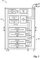
- Fig. 1 is a block diagram illustrating a side view of an embodiment of an electronics rack, which is a type of IT container commonly used in data centers.
- electronic rack 100 includes CDU 101, rack management unit (RMU) 102, and one or more server blades 103A-103D, collectively referred to as server blades 103.
- Server blades 103 can be inserted into an array of server slots respectively from front end 104 of electronic rack 100. Note that although only four server blades 103A-103D are shown, more or fewer server blades can be maintained within electronic rack 100.
- CDU 101 includes heat exchanger 111, liquid pump 112, and pump controller 110.
- Heat exchanger 111 can be a liquid-to-liquid heat exchanger.
- Heat exchanger 111 includes a first tube having a first pair of liquid connectors coupled to external liquid supply/return lines 131-132 to form a primary loop, where the connectors coupled to the external liquid supply/return lines 131-132 can be disposed or mounted on back end 105 of electronic rack 100.
- heat exchanger 111 further includes a second tube having a second pair of liquid connectors coupled to liquid manifold 125, which can include a supply manifold to supply cooling liquid to server blades 103 and a return manifold to return warmer liquid back to CDU 101.
- the processors can be mounted on the cold plates, where the cold plates include a liquid distribution channel embedded therein to receive the cooling liquid from the liquid manifold 125 and to return the cooling liquid carrying the heat exchanged from the processors back to the liquid manifold 125.
- Rack 100 is an example of an IT rack in which embodiments of a power delivery module, such as the ones shown in Figs. 3A et seq., can be used.
- Board 302 is rotatable about a first axis A1.
- Positioning screw 301 and output connector 304 are centered on axis A1 and are mounted on second side S2; output connector 304 can be used to connect power delivery module 300 to the main board of a piece of IT equipment such as a server (see, e.g., Figs. 4A-4B ).
- First side S1 of board 302 includes two pairs of electrical contacts: a first pair of spaced-apart electrical contacts, including a first negative contact (1-) and a first positive contact (1+), and a second pair of spaced-apart electrical contacts including a second negative contact (2-) and a second positive contact (2+).
- the negative and positive contacts maybe packaged together as a single module.
- Power clip module 310 has two main parts: a pair of power clips 318+ and 318- that electrically connect to a busbar, and a pair of contact pads 314+ and 314- that electrically couple power clips 318+ and 318- to one of the pair of electrical contacts on board 302-i.e., 1+/1- or 2+/2-.
- power clip module 310 includes a positioning screw 309 and a positioning nut 311.
- Power clip module 310 is attached to power delivery board 302 using a positioning screw 309 and positioning nut 311.
- Positioning screw 309 is inserted into clip mounting channel 308 and serves as a shaft around which power clip module 310 can rotate.
- first side S1 includes a first pair of horizontally spaced-apart electrical contacts, including a first negative contact (1-) and a first positive contact (1+). Also on side S1 is a second pair of horizontally spaced-apart electrical contacts, including a second negative contact (2-) and a second positive contact (2+).
- first and second pairs of electrical contacts are vertically spaced apart from each other on the board, with first positive contact 1+ directly above second negative contact 2-, and first negative contact 1- directly above second positive contact 2+. Put differently, first positive contact 1+ is diagonally across from second positive contact 2+, and first negative contact 1-is diagonally across from second negative contact 2-.
- Clip mounting channel 308 is positioned in board 302 in between the pairs of electrical contacts, so that the four electrical contacts and the clip mounting channel together form a quincunx.
- Figs. 3D-3E illustrate an embodiment of a power clip module 310.
- Fig. 3D is a plan view, Fig. 3E a cross-sectional view.
- Power clip module 310 forms the electrical connection between the busbar and the electrical contacts on power delivery module 300.
- Power clip module 310 in-eludes a clip module substrate 312 having a first side CS1 and a second side CS2.
- the chip module substrate can be made of any rigid material; in one embodiment, for instance, it can be made of a rigid and electrically insulating material.
- clip module substrate 312 can be made of an electrically conductive material, provided provisions are made for electrically insulating the contact pads and power clips from each other.
- chip module substrate 312 is round, but in other embodiments it can have a different shape, such as quadrilateral (see, e.g., Fig. 3G ).
- board 302 includes traces or connections that electrically couple both the first and second contact pairs to the power conditioning electronics, so that each pair of contacts has its own circuit routing to the power electronics.
- trace pair T1 shown in solid lines, electrically couple the first pair of contacts 1+/1-, also shown in solid lines, to the power electronics.
- Trace pair T1 includes a trace T1+ that is coupled to contact 1+ and a trace T1- that is coupled to contact 1-.
- trace pair T2 shown in dashed lines, electrically couple the second pair of contacts 2+/2- to the power electronics.
- Fig. 3G illustrates another embodiment of a power delivery module 350; some auxiliary structure for assisting the clip module rotation is not show in the figure.
- Power delivery module 350 is similar in most respects to power delivery module 300. The primary difference between power delivery modules 350 and 300 is the configuration of the power clip module.
- Power delivery module 350 includes a power clip module 352 that is quadrilateral in shape instead of round. Because of its quadrilateral shape, power clip module 352 also includes quadrilateral contact pads. Power clip module 352 may fully cover both pairs of electrical contacts (1+/1- and 2+/2-) on board 302, making them difficult to see and align properly. To address this problem, power clip module 352 can include a displacement buffer 354 on the two sides of the clips for ease of system installations and reliability enhancement. In additional embodiments, the power clip module can be packaged in different form factors, and multiple clip modules can be put on a power delivery board.
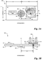
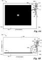
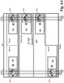
- a power delivery module (PDM) chassis 406 is also positioned within IT chassis 402 to receive and hold a power delivery module such as power delivery module 300 (see Figs. 3A-3F ).
- the PDM chassis provides structural support for the entire power module, including supporting the system installation (i.e., mounting and fixing structure).
- PDM chassis 406 can be a frame that engages with the edges of power delivery board 302 and with mounting/positioning screw 301, but in other embodiments PDM chassis can be constructed differently.
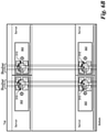
- PDM chassis 406 is fixed to IT chassis 402 by support 408 (visible in Fig. 4B ), so that PDM chassis 406 is stationary relative to IT chassis 402.
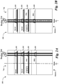
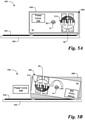
- Fig. 6C illustrates the result of rotating the right-side power delivery modules of Fig. 6A to be operable with a more central busbar.
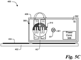
- power delivery boards 302 starting in the position shown in Fig. 6A , have been rotated 180 degrees (see Figs. 5A-5B ), so that power clip module 310 is positioned to couple with the more central busbar.
- Power clip module 310 has also been rotated 180 degrees (see Figs. 5B-5C ), so that the installation symbol points upward and the power clip module is in the correct orientation for the power clips to be coupled to their corresponding busbar conductors.
Landscapes
- Engineering & Computer Science (AREA)
- Microelectronics & Electronic Packaging (AREA)
- Theoretical Computer Science (AREA)
- General Engineering & Computer Science (AREA)
- Power Engineering (AREA)
- Physics & Mathematics (AREA)
- Computer Hardware Design (AREA)
- Human Computer Interaction (AREA)
- General Physics & Mathematics (AREA)
- Thermal Sciences (AREA)
- Power Sources (AREA)
- Rotary Switch, Piano Key Switch, And Lever Switch (AREA)
- Casings For Electric Apparatus (AREA)
- Coupling Device And Connection With Printed Circuit (AREA)
Applications Claiming Priority (1)
| Application Number | Priority Date | Filing Date | Title |
|---|---|---|---|
| US17/206,758 US11449112B1 (en) | 2021-03-19 | 2021-03-19 | Interoperable power delivery module for servers |
Publications (2)
| Publication Number | Publication Date |
|---|---|
| EP3965540A2 true EP3965540A2 (de) | 2022-03-09 |
| EP3965540A3 EP3965540A3 (de) | 2022-08-17 |
Family
ID=79730594
Family Applications (1)
| Application Number | Title | Priority Date | Filing Date |
|---|---|---|---|
| EP22152129.7A Withdrawn EP3965540A3 (de) | 2021-03-19 | 2022-01-19 | Vollständig kompatibles stromversorgungsmodul für server |
Country Status (4)
| Country | Link |
|---|---|
| US (1) | US11449112B1 (de) |
| EP (1) | EP3965540A3 (de) |
| JP (1) | JP7340640B2 (de) |
| CN (1) | CN115119452B (de) |
Families Citing this family (1)
| Publication number | Priority date | Publication date | Assignee | Title |
|---|---|---|---|---|
| US12455605B2 (en) * | 2023-04-25 | 2025-10-28 | Dell Products L.P. | Server information handling system with power interface component |
Family Cites Families (27)
| Publication number | Priority date | Publication date | Assignee | Title |
|---|---|---|---|---|
| DE2509406C3 (de) * | 1975-03-04 | 1979-02-22 | Standard Elektrik Lorenz Ag, 7000 Stuttgart | Verfahren zur automatischen Herstellung einer elektrischen Widerstandsschweißverbindung zwischen einem aus einem Metallband herausgestanzten Kontakt und einem Kontaktträger sowie Vorrichtung zur Durchführung des Verfahrens |
| JP3384132B2 (ja) * | 1994-08-31 | 2003-03-10 | 住友電装株式会社 | ワイヤーハーネスの製造方法並びにそれに用いられるジョイントコネクタ |
| US5777843A (en) * | 1996-07-12 | 1998-07-07 | Yazaki Corporation | Power distribution box and housing assembly |
| JP4475735B2 (ja) * | 2000-04-11 | 2010-06-09 | 富士通コンポーネント株式会社 | エンコーダ、その制御方法及び座標入力装置 |
| US6498716B1 (en) * | 2001-08-21 | 2002-12-24 | Compaq Information Technologies Group, L.P. | DC main power distribution |
| EP1654694B1 (de) * | 2003-08-05 | 2009-02-25 | Nxp B.V. | Modul mit mindestens zwei paaren von modulverbindungsplatten |
| US7780825B2 (en) * | 2007-05-21 | 2010-08-24 | Lam Research Corporation | Substrate gripper with integrated electrical contacts |
| EP2048746B1 (de) * | 2007-08-13 | 2016-10-05 | Tyco Electronics Nederland B.V. | Stromschienenanschlusssystem |
| JP6063330B2 (ja) * | 2012-12-14 | 2017-01-18 | 株式会社皆藤製作所 | 巻芯、及び捲回素子製造方法 |
| CN103971955B (zh) * | 2013-02-05 | 2019-07-26 | 阿斯科动力科技公司 | 并联切换开关的触点组件 |
| US10164373B1 (en) * | 2013-03-15 | 2018-12-25 | Koolance, Inc. | Automatic engagement system for liquid or power connections |
| JP6229361B2 (ja) * | 2013-08-01 | 2017-11-15 | 富士通株式会社 | 電子機器及び基板ユニット |
| CN104043907A (zh) * | 2014-05-29 | 2014-09-17 | 建科机械(天津)股份有限公司 | 一种旋转摩擦电阻对焊装置 |
| US9998404B2 (en) * | 2015-03-25 | 2018-06-12 | Lenovo Enterprise Solutions (Singapore) Pte. Ltd. | Automatically orienting hardware ports in a computing device |
| US9772663B2 (en) * | 2015-10-15 | 2017-09-26 | LiThul LLC | System and method for distributing power to rack mounted servers |
| US9986658B2 (en) * | 2015-12-03 | 2018-05-29 | Facebook, Inc | Power connection clip for a shelf in a server rack |
| EP3573166B1 (de) * | 2016-04-01 | 2022-02-09 | NS Co., Ltd. | Elektrodenanordnung |
| JP2018160572A (ja) | 2017-03-23 | 2018-10-11 | 富士通株式会社 | 電子装置 |
| JP6888469B2 (ja) * | 2017-08-04 | 2021-06-16 | 富士通株式会社 | 情報処理装置 |
| EP3849292A1 (de) * | 2017-09-01 | 2021-07-14 | Delta Electronics, Inc. | Wechselstromadapter und stromverteilungssystem mit diesem adapter |
| JP2019053700A (ja) | 2017-09-12 | 2019-04-04 | マジックハンド合同会社 | タブレットpc用の回転作業台 |
| US10470333B2 (en) * | 2018-01-05 | 2019-11-05 | Quanta Computer Inc. | Flexible chassis for different sized sleds |
| CN208805533U (zh) * | 2018-09-17 | 2019-04-30 | 北大先行泰安科技产业有限公司 | 一种恒温箱纽扣电池夹具固定装置 |
| US11177599B2 (en) * | 2019-01-28 | 2021-11-16 | TE Connectivity Services Gmbh | Power connector for a bus bar |
| CN210533267U (zh) * | 2020-04-15 | 2020-05-15 | 常州中联飞机制造有限公司 | 一种电机轴同轴度检具机构 |
| CN112469244A (zh) * | 2020-11-16 | 2021-03-09 | 南京阳中力商贸有限公司 | 一种用于智能手机的自动降温装置 |
| US11573615B2 (en) | 2021-03-05 | 2023-02-07 | Baidu Usa Llc | Rotational power delivery module for servers |
-
2021
- 2021-03-19 US US17/206,758 patent/US11449112B1/en active Active
- 2021-12-22 CN CN202111582757.2A patent/CN115119452B/zh active Active
-
2022
- 2022-01-19 EP EP22152129.7A patent/EP3965540A3/de not_active Withdrawn
- 2022-03-10 JP JP2022037008A patent/JP7340640B2/ja active Active
Also Published As
| Publication number | Publication date |
|---|---|
| JP7340640B2 (ja) | 2023-09-07 |
| JP2022084734A (ja) | 2022-06-07 |
| CN115119452A (zh) | 2022-09-27 |
| US20220300047A1 (en) | 2022-09-22 |
| CN115119452B (zh) | 2025-08-08 |
| EP3965540A3 (de) | 2022-08-17 |
| US11449112B1 (en) | 2022-09-20 |
Similar Documents
| Publication | Publication Date | Title |
|---|---|---|
| US7542268B2 (en) | Modular electronic systems and methods using flexible power distribution unit interface | |
| US7760516B2 (en) | Modular UPS systems and methods using modular interconnect assemblies | |
| US8917493B2 (en) | Power distribution device and server rack system using the same | |
| CN103092302A (zh) | 电源供应装置及服务器机柜供电系统 | |
| CA3037935A1 (en) | Unified connection array for battery module | |
| JP2008181516A (ja) | 調整可能なラック電力システムおよび方法 | |
| CN102882083A (zh) | 供电装置及具有供电装置的机柜供电系统 | |
| CN104104281A (zh) | 马达驱动装置及马达驱动系统 | |
| TWI830237B (zh) | 匯流排條組件 | |
| US7252524B1 (en) | Power interconnect assemblies and methods for configuring the same | |
| EP3996479A2 (de) | Rotierendes stromversorgungsmodul für server | |
| EP3965540A2 (de) | Interoperabler stromversorgungsmodul für server | |
| EP3996481A2 (de) | Ein kompatibles co-design für server- und rack-flüssigkeitsschnittstellen | |
| US10170263B2 (en) | Circuit breaker assemblies with changeable orientation | |
| US20170325351A1 (en) | Line Arrangement and Server Insert | |
| US10939572B2 (en) | Circuit board assembly | |
| CN114258240A (zh) | 电子机架流体分配系统 | |
| US9231357B1 (en) | Mid-plane assembly | |
| CN209913188U (zh) | 低功耗供电模块结构 | |
| CN120560457B (zh) | 服务器 | |
| US20250008698A1 (en) | Systems and methods for server level cooling | |
| US11388834B1 (en) | Power distribution board | |
| US12436587B2 (en) | Electronic device including power supplying apparatus, and computing system | |
| CA2260664A1 (en) | Rigid, multiconductor power distribution bus and modular equipment rack employing the same | |
| EP4629026A1 (de) | Stromüberbrückungsstruktur für racks und stromsammelschienenüberbrückungsvorrichtung dafür |
Legal Events
| Date | Code | Title | Description |
|---|---|---|---|
| PUAI | Public reference made under article 153(3) epc to a published international application that has entered the european phase |
Free format text: ORIGINAL CODE: 0009012 |
|
| STAA | Information on the status of an ep patent application or granted ep patent |
Free format text: STATUS: THE APPLICATION HAS BEEN PUBLISHED |
|
| AK | Designated contracting states |
Kind code of ref document: A2 Designated state(s): AL AT BE BG CH CY CZ DE DK EE ES FI FR GB GR HR HU IE IS IT LI LT LU LV MC MK MT NL NO PL PT RO RS SE SI SK SM TR |
|
| PUAL | Search report despatched |
Free format text: ORIGINAL CODE: 0009013 |
|
| AK | Designated contracting states |
Kind code of ref document: A3 Designated state(s): AL AT BE BG CH CY CZ DE DK EE ES FI FR GB GR HR HU IE IS IT LI LT LU LV MC MK MT NL NO PL PT RO RS SE SI SK SM TR |
|
| RIC1 | Information provided on ipc code assigned before grant |
Ipc: H05K 7/14 20060101AFI20220711BHEP |
|
| STAA | Information on the status of an ep patent application or granted ep patent |
Free format text: STATUS: THE APPLICATION IS DEEMED TO BE WITHDRAWN |
|
| 18D | Application deemed to be withdrawn |
Effective date: 20230218 |