EP3964483A1 - Elektrochemische zelle mit elektrisch leitfähigen diamantelektroden - Google Patents
Elektrochemische zelle mit elektrisch leitfähigen diamantelektroden Download PDFInfo
- Publication number
- EP3964483A1 EP3964483A1 EP21203306.2A EP21203306A EP3964483A1 EP 3964483 A1 EP3964483 A1 EP 3964483A1 EP 21203306 A EP21203306 A EP 21203306A EP 3964483 A1 EP3964483 A1 EP 3964483A1
- Authority
- EP
- European Patent Office
- Prior art keywords
- electrodes
- electrochemical cell
- fluid
- cell according
- pressure
- Prior art date
- Legal status (The legal status is an assumption and is not a legal conclusion. Google has not performed a legal analysis and makes no representation as to the accuracy of the status listed.)
- Withdrawn
Links
Images



Classifications
-
- C—CHEMISTRY; METALLURGY
- C25—ELECTROLYTIC OR ELECTROPHORETIC PROCESSES; APPARATUS THEREFOR
- C25B—ELECTROLYTIC OR ELECTROPHORETIC PROCESSES FOR THE PRODUCTION OF COMPOUNDS OR NON-METALS; APPARATUS THEREFOR
- C25B11/00—Electrodes; Manufacture thereof not otherwise provided for
- C25B11/02—Electrodes; Manufacture thereof not otherwise provided for characterised by shape or form
- C25B11/036—Bipolar electrodes
-
- C—CHEMISTRY; METALLURGY
- C02—TREATMENT OF WATER, WASTE WATER, SEWAGE, OR SLUDGE
- C02F—TREATMENT OF WATER, WASTE WATER, SEWAGE, OR SLUDGE
- C02F1/00—Treatment of water, waste water, or sewage
- C02F1/46—Treatment of water, waste water, or sewage by electrochemical methods
- C02F1/461—Treatment of water, waste water, or sewage by electrochemical methods by electrolysis
- C02F1/46104—Devices therefor; Their operating or servicing
-
- C—CHEMISTRY; METALLURGY
- C02—TREATMENT OF WATER, WASTE WATER, SEWAGE, OR SLUDGE
- C02F—TREATMENT OF WATER, WASTE WATER, SEWAGE, OR SLUDGE
- C02F1/00—Treatment of water, waste water, or sewage
- C02F1/46—Treatment of water, waste water, or sewage by electrochemical methods
- C02F1/461—Treatment of water, waste water, or sewage by electrochemical methods by electrolysis
- C02F1/46104—Devices therefor; Their operating or servicing
- C02F1/46109—Electrodes
-
- C—CHEMISTRY; METALLURGY
- C02—TREATMENT OF WATER, WASTE WATER, SEWAGE, OR SLUDGE
- C02F—TREATMENT OF WATER, WASTE WATER, SEWAGE, OR SLUDGE
- C02F1/00—Treatment of water, waste water, or sewage
- C02F1/46—Treatment of water, waste water, or sewage by electrochemical methods
- C02F1/461—Treatment of water, waste water, or sewage by electrochemical methods by electrolysis
- C02F1/467—Treatment of water, waste water, or sewage by electrochemical methods by electrolysis by electrochemical disinfection; by electrooxydation or by electroreduction
- C02F1/4672—Treatment of water, waste water, or sewage by electrochemical methods by electrolysis by electrochemical disinfection; by electrooxydation or by electroreduction by electrooxydation
-
- C—CHEMISTRY; METALLURGY
- C25—ELECTROLYTIC OR ELECTROPHORETIC PROCESSES; APPARATUS THEREFOR
- C25B—ELECTROLYTIC OR ELECTROPHORETIC PROCESSES FOR THE PRODUCTION OF COMPOUNDS OR NON-METALS; APPARATUS THEREFOR
- C25B11/00—Electrodes; Manufacture thereof not otherwise provided for
- C25B11/04—Electrodes; Manufacture thereof not otherwise provided for characterised by the material
- C25B11/042—Electrodes formed of a single material
- C25B11/043—Carbon, e.g. diamond or graphene
-
- C—CHEMISTRY; METALLURGY
- C25—ELECTROLYTIC OR ELECTROPHORETIC PROCESSES; APPARATUS THEREFOR
- C25B—ELECTROLYTIC OR ELECTROPHORETIC PROCESSES FOR THE PRODUCTION OF COMPOUNDS OR NON-METALS; APPARATUS THEREFOR
- C25B11/00—Electrodes; Manufacture thereof not otherwise provided for
- C25B11/04—Electrodes; Manufacture thereof not otherwise provided for characterised by the material
- C25B11/051—Electrodes formed of electrocatalysts on a substrate or carrier
- C25B11/055—Electrodes formed of electrocatalysts on a substrate or carrier characterised by the substrate or carrier material
- C25B11/057—Electrodes formed of electrocatalysts on a substrate or carrier characterised by the substrate or carrier material consisting of a single element or compound
-
- C—CHEMISTRY; METALLURGY
- C25—ELECTROLYTIC OR ELECTROPHORETIC PROCESSES; APPARATUS THEREFOR
- C25B—ELECTROLYTIC OR ELECTROPHORETIC PROCESSES FOR THE PRODUCTION OF COMPOUNDS OR NON-METALS; APPARATUS THEREFOR
- C25B11/00—Electrodes; Manufacture thereof not otherwise provided for
- C25B11/04—Electrodes; Manufacture thereof not otherwise provided for characterised by the material
- C25B11/051—Electrodes formed of electrocatalysts on a substrate or carrier
- C25B11/055—Electrodes formed of electrocatalysts on a substrate or carrier characterised by the substrate or carrier material
- C25B11/057—Electrodes formed of electrocatalysts on a substrate or carrier characterised by the substrate or carrier material consisting of a single element or compound
- C25B11/065—Carbon
-
- C—CHEMISTRY; METALLURGY
- C02—TREATMENT OF WATER, WASTE WATER, SEWAGE, OR SLUDGE
- C02F—TREATMENT OF WATER, WASTE WATER, SEWAGE, OR SLUDGE
- C02F1/00—Treatment of water, waste water, or sewage
- C02F1/46—Treatment of water, waste water, or sewage by electrochemical methods
- C02F1/461—Treatment of water, waste water, or sewage by electrochemical methods by electrolysis
- C02F1/46104—Devices therefor; Their operating or servicing
- C02F1/46109—Electrodes
- C02F2001/46128—Bipolar electrodes
-
- C—CHEMISTRY; METALLURGY
- C02—TREATMENT OF WATER, WASTE WATER, SEWAGE, OR SLUDGE
- C02F—TREATMENT OF WATER, WASTE WATER, SEWAGE, OR SLUDGE
- C02F1/00—Treatment of water, waste water, or sewage
- C02F1/46—Treatment of water, waste water, or sewage by electrochemical methods
- C02F1/461—Treatment of water, waste water, or sewage by electrochemical methods by electrolysis
- C02F1/46104—Devices therefor; Their operating or servicing
- C02F1/46109—Electrodes
- C02F2001/46133—Electrodes characterised by the material
-
- C—CHEMISTRY; METALLURGY
- C02—TREATMENT OF WATER, WASTE WATER, SEWAGE, OR SLUDGE
- C02F—TREATMENT OF WATER, WASTE WATER, SEWAGE, OR SLUDGE
- C02F1/00—Treatment of water, waste water, or sewage
- C02F1/46—Treatment of water, waste water, or sewage by electrochemical methods
- C02F1/461—Treatment of water, waste water, or sewage by electrochemical methods by electrolysis
- C02F1/46104—Devices therefor; Their operating or servicing
- C02F1/46109—Electrodes
- C02F2001/46133—Electrodes characterised by the material
- C02F2001/46138—Electrodes comprising a substrate and a coating
- C02F2001/46147—Diamond coating
-
- C—CHEMISTRY; METALLURGY
- C02—TREATMENT OF WATER, WASTE WATER, SEWAGE, OR SLUDGE
- C02F—TREATMENT OF WATER, WASTE WATER, SEWAGE, OR SLUDGE
- C02F2201/00—Apparatus for treatment of water, waste water or sewage
- C02F2201/002—Construction details of the apparatus
- C02F2201/004—Seals, connections
-
- C—CHEMISTRY; METALLURGY
- C02—TREATMENT OF WATER, WASTE WATER, SEWAGE, OR SLUDGE
- C02F—TREATMENT OF WATER, WASTE WATER, SEWAGE, OR SLUDGE
- C02F2201/00—Apparatus for treatment of water, waste water or sewage
- C02F2201/46—Apparatus for electrochemical processes
- C02F2201/461—Electrolysis apparatus
- C02F2201/46105—Details relating to the electrolytic devices
- C02F2201/4611—Fluid flow
-
- Y—GENERAL TAGGING OF NEW TECHNOLOGICAL DEVELOPMENTS; GENERAL TAGGING OF CROSS-SECTIONAL TECHNOLOGIES SPANNING OVER SEVERAL SECTIONS OF THE IPC; TECHNICAL SUBJECTS COVERED BY FORMER USPC CROSS-REFERENCE ART COLLECTIONS [XRACs] AND DIGESTS
- Y02—TECHNOLOGIES OR APPLICATIONS FOR MITIGATION OR ADAPTATION AGAINST CLIMATE CHANGE
- Y02E—REDUCTION OF GREENHOUSE GAS [GHG] EMISSIONS, RELATED TO ENERGY GENERATION, TRANSMISSION OR DISTRIBUTION
- Y02E60/00—Enabling technologies; Technologies with a potential or indirect contribution to GHG emissions mitigation
- Y02E60/30—Hydrogen technology
- Y02E60/36—Hydrogen production from non-carbon containing sources, e.g. by water electrolysis
Definitions
- the present invention relates to an electrochemical cell comprising a plurality of electrically conductive diamond electrodes.
- electrically conductive diamond electrodes can be used in such waste water treatment applications.
- EP0659691 describes such a use for electrically conductive diamond electrodes.
- Electrically conductive diamond material is believed to have a number of advantageous features in these applications including high hardness, high thermal conductivity, chemical inertness, and wide potential window. These features are considered to give electrically conductive diamond material the best combination of properties for electrochemical generation of highly reactive radicals for waste water purification while not damaging the electrodes thus allowing for prolonged use.
- One possible configuration for an electrochemical cell comprising diamond electrodes is a bipolar cell configuration.
- Such a configuration comprises a stack of bipolar electrodes provided between a single anode electrical connection and a single cathode electrical connection.
- a plurality of electrodes are disposed between the end anode and cathode such that when a large electric field is applied between the end anode and end cathode each intermediate electrode will have one side functioning as an anode and an opposite side functioning as a cathode (i.e. each intermediate electrode will be bipolar).
- Such an arrangement ensures that both sides of each electrically conductive diamond electrode are active which can be important given that the rate of electrochemical reaction is dependent on the active surface area of the electrodes.
- such a bipolar electrode configuration does not require electrical connections to be made to the intermediate bipolar electrodes which can be problematic for electrodes made of electrically conductive diamond material when compared with conventional metal electrodes.
- WO2008/029258 describes that solid, free-standing diamond electrodes have better lifetime in such applications but that achieving the required electrically conductivity in such thick, free-standing diamond electrodes can be difficult.
- WO2008/029258 described a method of achieving high boron doping concentrations in thick, free-standing diamond electrodes to achieve suitably high electrical conductivity and describes the use of such electrodes in a bipolar electrochemical cell configuration. Both parallel flow and serpentine flow configurations are suggested for use in a bipolar configuration with a parallel flow configuration being indicated as preferable.
- Figure 1 illustrates a bipolar electrochemical cell with a parallel flow configuration according to WO2008/029258
- Figure 2 illustrates a bipolar electrochemical cell with a serpentine flow configuration according to WO2008/029258
- Both these configurations comprise a bipolar stack of electrically conductive diamond electrodes including an end anode 2, an end cathode 4, and a plurality of intermediate bipolar electrodes 6 disposed between the anode 2 and cathode 4.
- the anode 2 and cathode 4 each comprise a single electrical connection 8, 10 coupled to a switching DC power supply 11.
- the configuration illustrated in Figure 1 comprises a plurality of parallel fluid paths 12 disposed between the plurality of electrically conductive diamond electrodes.
- the configuration illustrated in Figure 2 comprises a serpentine flow path 13 passing between the plurality of electrically conductive diamond electrodes.
- WO2012/049512 identifies a number of further problems with bipolar electrochemical cell configurations such as the one described in WO2008/029258 associated primarily with the fact that the diamond electrodes are supported only at the ends of the electrodes. These problems include the following: (1) thin, free standing (i.e. no support substrate) diamond electrodes are prone to mechanical failure; (2) thick diamond electrodes are expensive to manufacture; (3) the practical lower limit of electrode spacing to ensure that no electrical shorting occurs is higher than optimal for electrochemical performance; and (4) insufficient turbulence in the cell reduces mass transport rate at electrode surfaces.
- WO2012/049512 proposes that all these problems can be at least partially solved by providing a porous support structure (e.g.
- Such a support structure allows relatively thin diamond electrodes to be utilized without mechanical failure. Furthermore, such a support structure allows the electrode spacing to be narrowed without risk of electrical shorting. Further still, the support structure can function to increase turbulence and mass transport rate at electrode surfaces.
- WO2012/049512 represents the state of the art to date with respect to electrochemical cell configurations comprising free-standing, electrically conductive diamond electrodes.
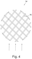
- Such a bipolar electrochemical cell configuration is illustrated in Figure 3 with Figure 4 showing an example of a porous support structure which can be disposed in the fluid paths between the diamond electrodes of the electrochemical cell of Figure 3 .
- the configuration illustrated in Figure 3 is similar to that illustrated in Figure 1 and comprises a bipolar stack of electrically conductive diamond electrodes including an end anode 2, an end cathode 4, and a plurality of intermediate bipolar electrodes 6 disposed between the anode 2 and cathode 4.
- the anode 2 and cathode 4 each comprise a single electrical connection 8, 10 coupled to a switching DC power supply 11.
- the configuration illustrated in Figure 3 comprises a plurality of parallel fluid paths 12 disposed between the plurality of electrically conductive diamond electrodes.
- the difference between the configuration illustrated in Figure 1 and the configuration illustrated in Figure 3 is that the configuration illustrated in Figure 3 comprises a porous support structure 14 which is disposed in the fluid paths between the diamond electrodes of the electrochemical cell.
- An example of such a porous support structure 14 is illustrated in Figure 4 and comprises a network of corrosion resistant plastic members 16 forming a porous wafer which can be sandwiched between adjacent electrically conductive diamond electrodes to support the electrodes while allowing fluid to flow between the adjacent electrically conductive diamond electrodes as indicated by the arrows in Figure 4 .
- a configuration according to that illustrated in Figure 3 and 4 includes a number of advantageous features including the following:
- WO2014/090663 discloses several alternatives to a bipolar cell configuration for diamond-based electrochemical cells.
- such alternative configurations can be more complex to implement and still require a relatively high operating voltage, thus meaning that cost of operation is still a critical issue for commercial applications.
- an electrochemical cell for treating a fluid comprising:
- An embodiment of the present invention is based on a modified version of the proprietor's own earlier diamond-based bipolar electrochemical cell configuration as described in WO2012/049512 .
- the configuration described in WO2012/049512 comprises a support structure, electrode spacing (5 mm), and seals configured to provide an operating pressure of approximately 1 bar and a current density of 5,000 Amp/m 2 over an electrode area of at least 20 cm 2 for an operating voltage of 8 V or a current density of 10,000 Amp/m 2 over an electrode area of at least 20 cm 2 for an operating voltage of 12 V.
- it has been found that it would be advantageous to increase the current density for a given applied potential while retaining a large electrode area. While larger current densities have been achieved for diamond-based electrochemical cell configurations with smaller electrodes, it is the combination of a high current density and a large electrode area which results in a more efficient electrochemical processing cell.
- Figure 5 illustrates an example of an electrochemical cell according to WO2012049512 .
- the configuration comprises the following components: main body assembly 20; spring loaded clamp 22; manifold 24; cassette assembly 26; end electrode 28; outer clamp ring 30; adapter 32; o-rings 34, 36, 38; studding 40; washer 42; nut 44; and studs 46, 48.
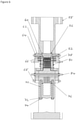
- Figure 6 illustrates a modified electrochemical cell according to an embodiment of the present invention.
- the configuration comprises the following components: o-ring 60; outer clamp ring 62; disk spring 64; trunnion 66; threaded studs 68, 70; washer 72; nut 74; main body 76; spring clamp 78; electrode assembly 80; cassette assembly 82; threaded stud 84; o-ring 86; and manifold 88.
- the present inventors have reduced the electrical resistivity of the diamond-based electrochemical cell in two major ways: (i) reducing the diamond electrode spacing; and (ii) redesigning the housing including the diamond electrode support structure and the pressure seals to increase the operating pressure and flow velocity.
- reducing the electrode spacing reduces the distance through which current is required to pass through the fluid between the electrodes thus reducing electrical resistance.
- Increasing the operating pressure reduces the size of gas bubbles in the fluid thus reducing the resistivity of the fluid.
- fluid flow velocity can be increased without exceeding operating pressure limits of such a modified electrochemical cell. Increasing fluid flow velocity aids in removal of bubbles from the surface of the diamond electrodes which again leads to a reduction in the resistivity of the fluid between the diamond electrodes.
- desired operating conditions must be balanced against tolerances of the components of the cell. For example, operating at too high a pressure can lead to fracture of the diamond electrodes, especially relatively thin, large area diamond electrodes. While the electrode area can be reduced to increase robustness to cracking, a reduction in electrode area reduces the oxidative capacity of the cell. As such, a balance must be struck between increased operating pressure, retention of large area electrodes, and robustness to leakage and cracking. Furthermore, reducing electrode spacing results in a reduced size of flow path for the fluid, which can cause problems of clogging of the flow path with solid particulates in the fluid. Furthermore, reducing the size of the flow path between the electrodes increases fluid flow velocity for a given flow rate.
- the present inventors have defined upper and lower limits for operating pressure and electrode spacing and redesigned the electrode support structure and pressure seals to achieve the desired electrode spacing and operating pressure while retaining a robust configuration.
- an electrochemical cell configuration which comprises:
- the electrodes may include two end electrodes and one or more intermediate electrodes disposed between the end electrodes forming a bipolar cell configuration.
- the electrochemical cell configuration is not limited to a bipolar cell configuration and the teachings of this specification can also be applied to alternative configurations as described, for example, in WO2014/090663 .
- the support structure and the pressure seals may be configured such that the operating pressure of the electrochemical cell is at least 3 or 4 bar and optionally no more than 8 or 5 Bar.
- the lower limit to the pressure configuration is defined by the desire to increase pressure and thus reduce the size of bubbles and thus the resistivity of the fluid.
- the upper limit to the pressure configuration is defined by the pressure at which leakage and/or electrode fracture occurs. This is dependent on the strength of the diamond electrodes, the support structure for the electrodes, and the pressure rating of the pressure seals.
- the pressure seals may be selected to fail at a pressure which is below that where the electrodes fracture.
- a leakage detection system may be provided to shut down the cell on detection of a leak. Such a combination of features limits cell damage if, for example, solid particulates block the flow path leading to an increase in pressure which could damage the cell.
- the electrode spacing may be no more than 3.5 mm, 3.0 mm, 2.5 mm, or 2 mm and optionally no less than 0.75 mm, 1 mm, 1.25 mm, or 1.5 mm.
- the upper limit for the electrode spacing is set by the desire to reduce the distance between the electrodes thus reducing the resistance of the cell and also providing an increased fluid flow velocity and pressure for a given volume flow rate which reduces the size and number of bubbles thus reducing the sensitivity of the fluid between the electrodes.
- the lower limit for the electrode spacing is set by the desire to avoid blockages caused by solid particulates and to ensure that the flow velocity and pressure is not so high that leakage or electrode fracture becomes problematic.
- the electrode area may be at least 40 cm 2 , 60 cm 2 , 80 cm 2 , 100 cm 2 , or 120 cm 2 and optionally no more than 200 cm 2 , 150 cm 2 , or 130 cm 2 .
- the electrode area is the surface area of one side of an electrode exposed to the fluid.
- the lower limit is set by the desire to have a large electrode area which increases oxidative capacity.
- the upper limit is set by the cost of the electrodes and the difficulty in supporting larger area diamond electrodes while operating at high pressures without the electrodes fracturing.
- the drive circuitry can be configured to apply a current density ⁇ 20,000 Amp/m 2 , ⁇ 25,000 Amp/m 2 , ⁇ 28,000 Amp/m 2 , or ⁇ 29,000 Amp/m 2 over the electrode area and optionally a current density no more than 40,000 Amp/m 2 , 35,000 Amp/m 2 , or 32,000 Amp/m 2 over the electrode area.
- These current densities are achieved for an operating voltage of no more than 20 V. It is desired to provide an extremely high current density in order to provide a high oxidative capacity. It is further desired that this should be provided at a relatively low voltage as available power may be limited at point of use and higher powers will result in large operating costs. The upper limit will be set by the desire to keep power requirements and cost down.
- the electrochemical cell may be provided with a pump system for pumping fluid through the cell with a flow velocity of at least 1 ms -1 , 1.3 ms -1 , 1.6 ms -1 , or 2 ms -1 and optionally no more than 10 ms -1 , 5 ms -1 , or 3 ms -1 .
- a flow velocity of at least 1 ms -1 , 1.3 ms -1 , 1.6 ms -1 , or 2 ms -1 and optionally no more than 10 ms -1 , 5 ms -1 , or 3 ms -1 .
- increased flow velocity can remove bubbles from the electrode surfaces and increase pressure thus reducing bubble size. Both of these effects result in a reduced resistivity and thus an increased current density for a given applied voltage.
- the flow velocity is too high then the pressure may increase to such an extent that leakage of diamond electrode fracture is problematic.
- the modified cell configuration as illustrated in Figure 6 now has a linear configuration with a flanged inlet and outlet.
- the electrode clamping force has been increased and the material of the O-ring seals changed taking into account chemical resistance, loading, and thermal effects.
- Finite Element Analysis has been utilized to optimize seal loading and materials selection based on loading/thermal effects.
- electrochemical cells designed to operate at higher current densities and water pressures increase the demand on the components used to seal and package the diamond electrodes.
- Polymer components exposed to the electrolyte are advantageously fluoropolymers or related materials to resist the increased chemical corrosion found in the local vicinity of electrolysis.
- the support interface between the diamond electrode and the backing clamp must be sufficiently stiff so as to prevent tensile stresses from fracturing the diamond electrodes while a compressive clamping force is applied to the sealing surface.
- the modified bipolar cell configuration comprises 21 boron doped diamond electrodes having a 1.6 mm spacing. Each electrode has a diameter of 130 mm and a thickness of 0.6 mm.
- the cell is configured to operate at a pressure of around 3 bar, a flow rate of around 25,000 litres / hour, a flow velocity > 1.0 m sec -1 , and a current density of 28,000 Am -2 or more. Power requirements are 120 to 250 kW and the Maximum Oxidation Capacity is approximately 2 kg h -1 compared with a previous value of 0.5 kg h -1 .
- the anode electrodes function to generate oxidizing species.
- the plurality of electrodes comprise a plurality of opposing pairs of electrodes, each opposing pair of electrodes comprising one electrode which is formed of a solid sheet of electrically conductive diamond material and another electrode which is formed of non-diamond material such as a metal or metal composite material.
- the plurality of electrodes comprise a plurality of opposing pairs of electrodes where both electrodes in each opposing pair of electrodes are formed of a solid sheet of electrically conductive diamond material.
- embodiments of the present invention can also be used to generate bleach (OCl - ) via the electrolysis of brine solutions.
Landscapes
- Chemical & Material Sciences (AREA)
- Engineering & Computer Science (AREA)
- Chemical Kinetics & Catalysis (AREA)
- Electrochemistry (AREA)
- Organic Chemistry (AREA)
- Water Supply & Treatment (AREA)
- Hydrology & Water Resources (AREA)
- Environmental & Geological Engineering (AREA)
- Life Sciences & Earth Sciences (AREA)
- General Chemical & Material Sciences (AREA)
- Materials Engineering (AREA)
- Metallurgy (AREA)
- Water Treatment By Electricity Or Magnetism (AREA)
- Physical Or Chemical Processes And Apparatus (AREA)
- Electrodes For Compound Or Non-Metal Manufacture (AREA)
- Electrolytic Production Of Non-Metals, Compounds, Apparatuses Therefor (AREA)
Applications Claiming Priority (3)
| Application Number | Priority Date | Filing Date | Title |
|---|---|---|---|
| GBGB1522500.6A GB201522500D0 (en) | 2015-12-21 | 2015-12-21 | Electrochemical cell comprising electrically conductive diamond electrodes |
| EP16801248.2A EP3393979A1 (de) | 2015-12-21 | 2016-11-25 | Elektrochemische zelle mit elektrisch leitfähigen diamantelektroden |
| PCT/EP2016/078782 WO2017108327A1 (en) | 2015-12-21 | 2016-11-25 | Electrochemical cell comprising electrically conductive diamond electrodes |
Related Parent Applications (1)
| Application Number | Title | Priority Date | Filing Date |
|---|---|---|---|
| EP16801248.2A Division EP3393979A1 (de) | 2015-12-21 | 2016-11-25 | Elektrochemische zelle mit elektrisch leitfähigen diamantelektroden |
Publications (1)
| Publication Number | Publication Date |
|---|---|
| EP3964483A1 true EP3964483A1 (de) | 2022-03-09 |
Family
ID=55311321
Family Applications (2)
| Application Number | Title | Priority Date | Filing Date |
|---|---|---|---|
| EP21203306.2A Withdrawn EP3964483A1 (de) | 2015-12-21 | 2016-11-25 | Elektrochemische zelle mit elektrisch leitfähigen diamantelektroden |
| EP16801248.2A Withdrawn EP3393979A1 (de) | 2015-12-21 | 2016-11-25 | Elektrochemische zelle mit elektrisch leitfähigen diamantelektroden |
Family Applications After (1)
| Application Number | Title | Priority Date | Filing Date |
|---|---|---|---|
| EP16801248.2A Withdrawn EP3393979A1 (de) | 2015-12-21 | 2016-11-25 | Elektrochemische zelle mit elektrisch leitfähigen diamantelektroden |
Country Status (6)
| Country | Link |
|---|---|
| US (1) | US11346012B2 (de) |
| EP (2) | EP3964483A1 (de) |
| JP (3) | JP2019508223A (de) |
| CN (1) | CN108602697A (de) |
| GB (2) | GB201522500D0 (de) |
| WO (1) | WO2017108327A1 (de) |
Families Citing this family (3)
| Publication number | Priority date | Publication date | Assignee | Title |
|---|---|---|---|---|
| EP3386924B1 (de) * | 2016-02-05 | 2019-08-28 | Siemens Energy, Inc. | Elektrooxidation bei erhöhten drücken |
| CN108204968B (zh) * | 2018-02-08 | 2019-10-08 | 华南师范大学 | 一种芯片在对葡萄糖和尿酸做同时检测中的应用 |
| GB2601149B (en) * | 2020-11-19 | 2024-01-17 | Suretol Ltd | Electrochemical device for producing biocide solutions |
Citations (6)
| Publication number | Priority date | Publication date | Assignee | Title |
|---|---|---|---|---|
| EP0659691A1 (de) | 1993-12-22 | 1995-06-28 | Eastman Kodak Company | Abwasserbehandlung durch Elektrolyse mit einer dotierten Diamantanode |
| WO2008029258A2 (en) | 2006-09-05 | 2008-03-13 | Element Six Limited | Solid electrode |
| US20100006450A1 (en) * | 2006-11-10 | 2010-01-14 | Element Six Limited | Diamond electrode |
| WO2012049512A2 (en) | 2010-10-14 | 2012-04-19 | Advanced Oxidation Limited | A bipolar cell for a reactor |
| WO2014090663A1 (en) | 2012-12-12 | 2014-06-19 | Element Six Technologies Limited | Electrochemical cell comprising electrically conductive diamond electrodes |
| EP2772469A1 (de) * | 2013-02-27 | 2014-09-03 | Bayer Technology Services GmbH | Mikro-Lamellenelektrodenzelle sowie deren Verwendung |
Family Cites Families (7)
| Publication number | Priority date | Publication date | Assignee | Title |
|---|---|---|---|---|
| EP1254972A1 (de) * | 2001-05-01 | 2002-11-06 | CSEM Centre Suisse d'Electronique et de Microtechnique SA | Modulare elektrochemische Zelle |
| JP3727579B2 (ja) * | 2001-12-12 | 2005-12-14 | 株式会社荏原製作所 | 水熱電気分解反応装置及び電極 |
| CN1303254C (zh) * | 2004-04-16 | 2007-03-07 | 清华大学 | 一种用于污水处理的电解槽 |
| JP2006225694A (ja) * | 2005-02-16 | 2006-08-31 | Kurita Water Ind Ltd | 電気分解セル |
| CN101085694B (zh) * | 2007-03-15 | 2010-11-03 | 归建明 | 电解催化裂解污水处理装置 |
| GB2490913B (en) * | 2011-05-17 | 2015-12-02 | A Gas Internat Ltd | Electrochemical cell and method for operation of the same |
| JP5900482B2 (ja) * | 2013-12-26 | 2016-04-06 | 栗田工業株式会社 | 水回収方法及び装置 |
-
2015
- 2015-12-21 GB GBGB1522500.6A patent/GB201522500D0/en not_active Ceased
-
2016
- 2016-11-25 WO PCT/EP2016/078782 patent/WO2017108327A1/en not_active Ceased
- 2016-11-25 EP EP21203306.2A patent/EP3964483A1/de not_active Withdrawn
- 2016-11-25 EP EP16801248.2A patent/EP3393979A1/de not_active Withdrawn
- 2016-11-25 CN CN201680080113.4A patent/CN108602697A/zh active Pending
- 2016-11-25 US US16/063,637 patent/US11346012B2/en active Active
- 2016-11-25 GB GB1619940.8A patent/GB2545801B/en active Active
- 2016-11-25 JP JP2018532728A patent/JP2019508223A/ja active Pending
-
2020
- 2020-12-11 JP JP2020205706A patent/JP2021073080A/ja active Pending
-
2022
- 2022-12-27 JP JP2022209286A patent/JP2023040102A/ja not_active Abandoned
Patent Citations (6)
| Publication number | Priority date | Publication date | Assignee | Title |
|---|---|---|---|---|
| EP0659691A1 (de) | 1993-12-22 | 1995-06-28 | Eastman Kodak Company | Abwasserbehandlung durch Elektrolyse mit einer dotierten Diamantanode |
| WO2008029258A2 (en) | 2006-09-05 | 2008-03-13 | Element Six Limited | Solid electrode |
| US20100006450A1 (en) * | 2006-11-10 | 2010-01-14 | Element Six Limited | Diamond electrode |
| WO2012049512A2 (en) | 2010-10-14 | 2012-04-19 | Advanced Oxidation Limited | A bipolar cell for a reactor |
| WO2014090663A1 (en) | 2012-12-12 | 2014-06-19 | Element Six Technologies Limited | Electrochemical cell comprising electrically conductive diamond electrodes |
| EP2772469A1 (de) * | 2013-02-27 | 2014-09-03 | Bayer Technology Services GmbH | Mikro-Lamellenelektrodenzelle sowie deren Verwendung |
Non-Patent Citations (1)
| Title |
|---|
| "SEMICONDUCTORS AND SEMIMETALS.", vol. 77, 1 January 2004, ACADEMIC PRESS, SAN DIEGO, CA., US, ISSN: 0080-8784, article WERNER HAENNI ET AL: "Chapter 5 Industrial applications of diamond electrodes", pages: 149 - 196, XP055333038, DOI: 10.1016/S0080-8784(04)80017-6 * |
Also Published As
| Publication number | Publication date |
|---|---|
| JP2021073080A (ja) | 2021-05-13 |
| US20180371629A1 (en) | 2018-12-27 |
| GB201619940D0 (en) | 2017-01-11 |
| GB2545801B (en) | 2020-10-21 |
| CN108602697A (zh) | 2018-09-28 |
| JP2019508223A (ja) | 2019-03-28 |
| GB2545801A (en) | 2017-06-28 |
| GB201522500D0 (en) | 2016-02-03 |
| JP2023040102A (ja) | 2023-03-22 |
| US11346012B2 (en) | 2022-05-31 |
| WO2017108327A1 (en) | 2017-06-29 |
| EP3393979A1 (de) | 2018-10-31 |
Similar Documents
| Publication | Publication Date | Title |
|---|---|---|
| JP2023040102A (ja) | 導電性ダイヤモンド電極を有する電気化学セル | |
| CN103328690B (zh) | 用于臭氧生成的电解池 | |
| JP5883297B2 (ja) | 固体電極 | |
| CN103282551B (zh) | 用于反应器的双极电解槽 | |
| GB2490912A (en) | An electrode comprising a plurality of lands with a layer of diamond thereon | |
| WO2007060807A1 (ja) | ダイヤモンド電極、その製造方法、および電解槽 | |
| CN101511453A (zh) | 电去离子系统及其多孔电极和形成多孔电极的方法 | |
| JP7093362B2 (ja) | 電気的保護を改善した廃水処理用の電気化学セル | |
| CN104278289B (zh) | 电解电极设备以及具备该电解电极设备的电解水生成装置 | |
| CN105026317B (zh) | 微层电极电解池及其用途 | |
| US10858744B2 (en) | Ozone generators, methods of making ozone generators, and methods of generating ozone | |
| WO2014141587A1 (ja) | 電解水生成装置 | |
| KR101305656B1 (ko) | 황산 전해조 및 황산 전해조를 이용한 황산 리사이클형 세정 시스템 | |
| JP5341547B2 (ja) | 水電解システム | |
| JP4623307B2 (ja) | 電解セルおよび該電解セルを用いた硫酸リサイクル型洗浄システム | |
| JP6403052B2 (ja) | 電解用電極ユニット | |
| KR101159306B1 (ko) | 전극구조 | |
| EP2289852A1 (de) | Verbesserte Elektrolysezelle zur Erzeugung von Chlor in einem Becken | |
| RU2296108C1 (ru) | Диафрагменный электролизер | |
| KR101070826B1 (ko) | 전극 구조 | |
| KR101817193B1 (ko) | 전기분해장치용 전해조 | |
| EP4713981A1 (de) | Elektrosynthetische oder elektroenergiezelle, system und betriebsverfahren | |
| JP2026001723A (ja) | オゾン水生成装置 | |
| GB2557193A (en) | Electrode and electrochemical cell comprising the same | |
| CN102373495A (zh) | 电解装置 |
Legal Events
| Date | Code | Title | Description |
|---|---|---|---|
| PUAI | Public reference made under article 153(3) epc to a published international application that has entered the european phase |
Free format text: ORIGINAL CODE: 0009012 |
|
| STAA | Information on the status of an ep patent application or granted ep patent |
Free format text: STATUS: REQUEST FOR EXAMINATION WAS MADE |
|
| 17P | Request for examination filed |
Effective date: 20211018 |
|
| AC | Divisional application: reference to earlier application |
Ref document number: 3393979 Country of ref document: EP Kind code of ref document: P |
|
| AK | Designated contracting states |
Kind code of ref document: A1 Designated state(s): AL AT BE BG CH CY CZ DE DK EE ES FI FR GB GR HR HU IE IS IT LI LT LU LV MC MK MT NL NO PL PT RO RS SE SI SK SM TR |
|
| P01 | Opt-out of the competence of the unified patent court (upc) registered |
Effective date: 20230524 |
|
| STAA | Information on the status of an ep patent application or granted ep patent |
Free format text: STATUS: EXAMINATION IS IN PROGRESS |
|
| 17Q | First examination report despatched |
Effective date: 20240415 |
|
| STAA | Information on the status of an ep patent application or granted ep patent |
Free format text: STATUS: THE APPLICATION HAS BEEN WITHDRAWN |
|
| 18W | Application withdrawn |
Effective date: 20250116 |