EP3962703B1 - Zuführung von nahrungsmitteln in schneide- oder portioniermaschinen - Google Patents
Zuführung von nahrungsmitteln in schneide- oder portioniermaschinen Download PDFInfo
- Publication number
- EP3962703B1 EP3962703B1 EP20728121.3A EP20728121A EP3962703B1 EP 3962703 B1 EP3962703 B1 EP 3962703B1 EP 20728121 A EP20728121 A EP 20728121A EP 3962703 B1 EP3962703 B1 EP 3962703B1
- Authority
- EP
- European Patent Office
- Prior art keywords
- food product
- product
- feed rate
- cutter
- cutting
- Prior art date
- Legal status (The legal status is an assumption and is not a legal conclusion. Google has not performed a legal analysis and makes no representation as to the accuracy of the status listed.)
- Active
Links
Images


Classifications
-
- B—PERFORMING OPERATIONS; TRANSPORTING
- B26—HAND CUTTING TOOLS; CUTTING; SEVERING
- B26D—CUTTING; DETAILS COMMON TO MACHINES FOR PERFORATING, PUNCHING, CUTTING-OUT, STAMPING-OUT OR SEVERING
- B26D5/00—Arrangements for operating and controlling machines or devices for cutting, cutting-out, stamping-out, punching, perforating, or severing by means other than cutting
- B26D5/007—Control means comprising cameras, vision or image processing systems
-
- B—PERFORMING OPERATIONS; TRANSPORTING
- B26—HAND CUTTING TOOLS; CUTTING; SEVERING
- B26D—CUTTING; DETAILS COMMON TO MACHINES FOR PERFORATING, PUNCHING, CUTTING-OUT, STAMPING-OUT OR SEVERING
- B26D7/00—Details of apparatus for cutting, cutting-out, stamping-out, punching, perforating, or severing by means other than cutting
- B26D7/06—Arrangements for feeding or delivering work of other than sheet, web, or filamentary form
- B26D7/0625—Arrangements for feeding or delivering work of other than sheet, web, or filamentary form by endless conveyors, e.g. belts
-
- B—PERFORMING OPERATIONS; TRANSPORTING
- B26—HAND CUTTING TOOLS; CUTTING; SEVERING
- B26D—CUTTING; DETAILS COMMON TO MACHINES FOR PERFORATING, PUNCHING, CUTTING-OUT, STAMPING-OUT OR SEVERING
- B26D7/00—Details of apparatus for cutting, cutting-out, stamping-out, punching, perforating, or severing by means other than cutting
- B26D7/06—Arrangements for feeding or delivering work of other than sheet, web, or filamentary form
- B26D7/0683—Arrangements for feeding or delivering work of other than sheet, web, or filamentary form specially adapted for elongated articles
-
- B—PERFORMING OPERATIONS; TRANSPORTING
- B65—CONVEYING; PACKING; STORING; HANDLING THIN OR FILAMENTARY MATERIAL
- B65G—TRANSPORT OR STORAGE DEVICES, e.g. CONVEYORS FOR LOADING OR TIPPING, SHOP CONVEYOR SYSTEMS OR PNEUMATIC TUBE CONVEYORS
- B65G43/00—Control devices, e.g. for safety, warning or fault-correcting
- B65G43/08—Control devices operated by article or material being fed, conveyed or discharged
-
- B—PERFORMING OPERATIONS; TRANSPORTING
- B26—HAND CUTTING TOOLS; CUTTING; SEVERING
- B26D—CUTTING; DETAILS COMMON TO MACHINES FOR PERFORATING, PUNCHING, CUTTING-OUT, STAMPING-OUT OR SEVERING
- B26D2210/00—Machines or methods used for cutting special materials
- B26D2210/02—Machines or methods used for cutting special materials for cutting food products, e.g. food slicers
Definitions
- the present invention relates to a food processing machine and a method of cutting slices or portions from a food product in a food processing machine and more particularly to the feeding of a food product towards the cutter of such a machine.
- EP-A-2878203 forming the basis for the preambles of the independent claims, relates to a cutting apparatus for cutting food products which includes first and second scanning devices and first and second cutting units.
- WO2004/034794 concerns an apparatus for portion cutting of products.
- the apparatus includes a scanning means, cutting means and conveying means for transporting the product from the scanning means to the cutting means.
- the present invention is directed at a food processing machine comprising:
- a food product is continuously constrained by the transport system as the food product travels through the sensing region and from the sensing region to the cutter, and the first and second feeder systems engage with both upper and lower surfaces of a food product to constrain it.
- This independent feed rate control provides flexibility in the way in which the food product is fed through a sensing region and to the cutter. By providing a sensing apparatus within the same machine as the cutter, the overall footprint of a processing configuration which provides product profile detection and cutting can be reduced. Furthermore, the independent control of the sensing and cutting feed rates may allow the overall speed of carrying out both these processes within the same machine to be increased. The feed rates may be adjusted for different food product lengths where appropriate to increase the rate of product throughput. The independent feed rate control may allow the sensing and cutting feed rates to be different as and when required.
- Each feeder system may be formed of one or more product drivers.
- Each driver may comprise an endless track or belt, a roller, a spiked roller, an array or series of rollers, endless toothed tracks, or endless spiked chains, for example.
- the first feeder system may be located upstream of the sensing region.
- the second feeder system feeds the food product towards and past the cutter so as to control the size of each slice or portion cut from the leading end of the food product.
- a food product is continuously constrained by the transport system as the food product travels through the sensing region and from the sensing region to the cutter.
- a sensing apparatus in the same machine as the cutter, it is possible to provide continuous constraint of the food product through the sensing region and from the sensing region to the cutter. This facilitates more precise control of the size of the slices or portions cut from the food product by the cutter.
- product scanning is carried out in a machine separate to that used for cutting the food product. In such an arrangement, there is a risk that the product may shift laterally or rotate between scanning and cutting, thereby reducing the accuracy of the cutting process.
- a food product may be restrained against movement relative to the surface(s) of the transport system which are in contact with the food product. In this way, the lateral position and/or the orientation of the food product within the machine may be continuously controlled whilst it is carried by the transport system through the sensing region and to the cutter.
- the first and second feeder systems engage with both upper and lower surfaces of a food product so as to constrain it.
- the transport system may be configured to feed a food product at least part of the way towards the cutter (that is, before cutting of the product has started) at a different, preferably higher feed rate than the cutting feed rate used for the food product during cutting of the product (or the preceding food product).
- the cutting feed rate may be the speed (or average speed) at which the product is moved towards the cutter whilst the product is downstream of the sensing region, and more particularly, may be the speed (or average speed) at which the product is moved towards the cutter whilst slices or portions are cut from its leading end. If groups of slices or portions are being cut from the food product, it may be necessary to pause the feeding of the product towards the cutter briefly to allow a completed group to be transported away from the cutter before cutting slices or portions of the next group. In this case, the cutting feed rate may be the average speed with which the food product is moved towards the cutter including any such pauses whilst slices or portions are cut from its leading end.
- the transport system may be configured to feed a food product through the sensing region at a sensing feed rate which is greater or less than the cutting feed rate used for the food product during cutting of the product (or the immediately preceding product).
- a slower sensing feed rate may be selected to allow the profile of the food product to be sensed or scanning at a higher resolution.
- the transport system may be switchable between a first feed mode in which the sensing feed rate substantially matches the cutting feed rate, and a second feed mode in which a food product is fed by the transport system at least part of the way towards the cutter at a higher feed rate than the cutting feed rate used for the food product during cutting thereof.
- This versatility may allow the feeding of a food product to be altered depending on the food product length.
- the transport system may be selectively operable in one of a first retract mode in which both the first and second feeder systems are operated so as to retract a food product away from the cutter, and a second retract mode in which only the second feeder system is operated so as to retract a food product away from the cutter. If the machine is being used to cut groups of slices or portions, it may be desirable to briefly retract the food product away from the cutter to pause slicing, allowing a completed group to be conveyed away from the cutter before cutting of the next group is started.
- first and second feeder systems With a longer product, it may be desirable to use both the first and second feeder systems to retract the food product in this manner, whilst a shorter product, or a remaining portion of a longer product may only be in engagement with the second feeder system and so only the second feeder system would need to be operated so as to retract a food product away from the cutter. Operation of the first feeder system could then take place independently of the second feeder system.
- the first feeder system may comprise product drivers located upstream and downstream from the sensing region.
- a gap may be defined between the upstream and downstream drivers of the first feeder system to expose a surface of the food product so that its profile can be sensed by the sensing apparatus.
- the upstream and downstream product drivers of the first feeder system may be driven by a common motor. Both upper and lower surfaces of a food product may be exposed between the upstream and downstream product drivers. In some preferred embodiments, a complete circumferential lateral profile of a food product may be exposed between the upstream and downstream product drivers.
- the first feeder system may comprise first upper and first lower product drivers configured to engage with upper and lower surfaces of a food product, respectively. They may be located upstream of the sensing region.
- the first upper product driver may comprise a roller or a conveyor, for example.
- the first upper product driver may be carried by an arm which is pivotably mounted in the machine.
- the first feeder system may define a first support plane on which food products are fed along a first feed direction by the first feeder system, and the arm may be rotatable about an axis perpendicular to the first feed direction and parallel to the support plane.
- the first lower product driver may comprise an endless track or belt.
- the roller may be biased or urged in a downwards direction towards the lower product feeder by the pivotable arm.
- the biasing force exerted by the arm may be varied by the machine. For example, a lower biasing force may be applied as a product is initially inserted below the roller, and the biasing force may then be increased by the machine. The biasing force may be increased after the roller has been raised by the product so that the roller more reliably constrains the product against the lower product feeder.
- the downstream product drivers of the first feeder system may comprise downstream upper and downstream lower endless drive tracks or belts configured to engage upper and lower surfaces of a food product, respectively.
- the second feeder system may comprise second upper and second lower product drivers configured to engage with upper and lower surfaces of a food product, respectively.
- the second upper product driver may comprise a track or belt.
- the second upper product driver may be pivotably mounted in the machine.
- the second feeder system may define a second support plane on which food products are fed along a second feed direction by the second feeder system, and the second upper product driver may be rotatable about an axis perpendicular to the second feed direction and parallel to the second support plane. This enables the driver to provide improved product constraint close to the cutter, as the driver can pivot to suit variations in the shape of the upper surface of a product.
- the transport system may be arranged to carry food products to the cutter along a food product flow path which is inclined relative to horizontal. This may facilitate improved control of slices or portions as they fall away from the cutter.
- An upper surface profile only of the product may be scanned in the sensing region. Alternatively, some or all of the other sides of the product may also be sensed.
- the scanners may utilise LEDs or line lasers to project a line onto the surface of the product which is then detected using sensors such as cameras.
- an array or pattern of lines (such as a plurality of parallel or intersecting lines), or any array of dots or dashes may be projected onto the food product for detection by the machine.
- the line profiles or other patterns generated by the lasers may then be processed by the machine to determine the profile of the product.
- sensing systems for determining the external shape of a food product may be utilised, such as X-ray or "time-of-flight" systems, or sensing systems employing an array of photoelectric detectors, for example.
- the present invention is also directed at a method of cutting portions from a food product in a food processing machine in which food products are transported through a sensing region to a cutter, the method comprising controlling a sensing feed rate at which a food product is fed through the sensing region by a first feeder system independently of a cutting feed rate downstream of the sensing region at which a food product is fed towards the cutter by a second feeder system.
- the method of cutting portions includes continuously constraining the food product as it travels through the sensing region and from the sensing region to the cutter, with the first and second feeder systems engaging with both upper and lower surfaces of a food product to constrain it.
- the food processing machine may operate to feed food product at least part of the way towards the cutter at a higher feed rate than the cutting feed rate used for the food product during cutting thereof. More particularly, the machine may feed a food product through the sensing region at a higher feed rate than the cutting feed rate used for the food product during cutting thereof.
- the method may include switching the transport system between a first feed mode in which the sensing feed rate substantially matches the cutting feed rate of the product, and a second feed mode in which a food product is fed at least part of the way towards the cutter at a higher feed rate than the cutting feed rate used for the food product during cutting thereof.
- Further methods embodying the present disclosure may include selectively operating the transport system in one of a first retract mode in which both the first and second feeder systems operate so as to retract a food product away from the cutter, and a second retract mode in which only the second feeder system operates so as to retract a food product away from the cutter.
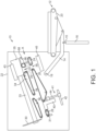
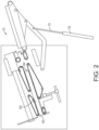
- Figures 1 to 4 are side views of the interior of a food processing machine according to an embodiment of the invention to illustrate operation of the machine.
- Figures 1 and 2 are side views of the interior of a food processing machine 10 for cutting slices or portions from elongate food products.
- the operation of the machine is governed by an electronic control system (not shown).
- the food products are initially fed to a loading bed 12 carried by a loading arm 14.
- the loading bed has a horizontal orientation in Figure 1 ready to receive the next product.
- the arm is coupled to a piston 15 which extends into a drive cylinder 16.
- the arm is rotatably mounted on a pivot 18.
- the arm is pivotable about pivot 18 into a raised position shown in Figure 2 by driving the piston 15 with drive cylinder 16.
- the loading bed includes a driven conveyor 20 which is operable to load a food product into the main body 22 of the machine when the loading arm is in the position shown in Figure 2 .
- the product is then fed in direction "A" marked in Figure 1 along a food product flow path through the main body 22.
- the food product flow path through the main body 22 is inclined at an angle relative to horizontal.
- the main body includes lower product feeders 24, 26 and 28 which are located below the food product flow path and operable to drive a food product towards a cutting region of the machine.
- slices or portions are cut from the leading end of the food product by a rotatable involute blade 30 that contacts the food product.
- the blade is mounted on a shaft 33 which is driven by a motor 35.
- Upper product feeders 32, 34 and 36 are provided to engage with an upper surface of a food product to constrain it against the lower feeders and drive it towards the cutting region.
- the blade cuts the product as it passes over a cutting edge 31.
- the cutting blade may alternatively be a circular blade mounted on an orbital drive assembly, a sickle blade, a knife, or a circular blade mounted on a rotating arm, for example.
- the lower product feeders 24, 26 and the upper product feeders 32, 34 form a first feeder system and may each be driven by a first, common motor (not shown).
- the lower product feeder 28 and upper product feeder 36 form a second feeder system and may each be driven by a second, common motor (not shown).
- the motors may be servo motors for example.
- the machine As a food product is fed into the machine, it enters a sensing region 29 of the machine.
- the food product passes below a first gap 37 defined between upper product feeders 32 and 34 and above a second gap 39 defined between lower product feeders 24 and 26.
- the gaps allow the upper and lower surface profiles of the food product to be detected using upper and lower scanners 43 and 45, respectively.
- One or both of the upper and lower scanners 43, 45 may comprise a scanner or sensing system of one of the types described above.
- the machine includes an end gripper 40.
- the end gripper is shown in its stowed position below the food product flow path.
- the end gripper is carried by a gripper drive assembly 41 which is operable to move the end gripper relative to the main body 22 of the machine to bring it into engagement with a trailing end 64 of a food product 60.
- the gripper drive assembly includes a first pair of parallel support rods 44, which extend perpendicular to the food product flow path.
- the end gripper is mounted for reciprocating motion along these rods.
- a second pair of support rods 42 extends parallel to the food product flow path. They carry the first pair of support rods 44 and the first pair is mounted so as to be able to reciprocate back and forth along the second pair of rods.
- the end gripper is raised by the gripper drive assembly after a food product has passed over the end gripper and then brought into engagement with the trailing end of the product during the final stage of slicing a product.
- the end gripper is able to grip the end of the product with teeth (not shown) to stabilise the trailing end and also to remove the end region of a food product that is not to be sliced (referred to as the "butt end") and prevent it from continuing past the blade.
- a food product 60 is shown in Figure 2 by way of illustration.
- the machine is operable to handle a wide range of product lengths and heights. For example, products could range between 300 and 750mm in length and 100 to 130mm in height.
- the food product shown in Figure 2 is relatively long and some slices have already been cut from its leading end 62.
- Product 60 was loaded into the machine from loading bed 12 by activating the driven conveyor 20 of the loading bed to move the product along direction A. The product was then entrained within the machine between the upper product feeder 32 and the lower product feeder 24.
- the upper product feeder 32 is in the form of a spiked roller which is rotatably mounted on an arm 66.
- the arm 66 is in turn pivotably coupled to the main body 22 of the machine by a pivot 68.
- Pivot 68 has a pivotable axis which is perpendicular to the in-feed direction A and parallel to a plane defined by the upper surfaces of the lower product feeders.
- the lower product feeder 24 comprises a set of toothed endless chains or tracks for engaging with a lower surface of a food product and driving it in direction A.
- roller 32 on arm 66 provides more reliable constraint of products having different heights as they enter and pass into the machine.
- the upper product feeder 32 may be a conveyor.
- the lower product feeder is preferably in the form of a conveyor elongated along direction A rather than a roller to provide greater support for the underside of a product as it enters the machine. This enables the loading bed 12 to lower sooner as the product is fed into the machine due to the control of the product provided by the feeder 24.
- the upper product feeder 32 and lower product feeder 24 co-operate so as to constrain movement of the food product relative to the portions of the feeders in engagement with it. This ensures that the product is continuously and reliably constrained as it is fed between the gaps 37 and 39.
- the motion of the food product as it passes between the gaps is therefore closely and continuously controlled by the machine during scanning thereof by the upper and lower scanners 43 and 45.
- upper product feeder 34 and lower product feeder 26 Each of these feeders may comprise a set of toothed chains or tracks. These feeders are also operable to drive the food product along direction A.
- feeders 24, 26, 32 and 34 are driven by a common motor. They therefore co-operate to drive a product which is in engagement with all four feeders as it passes between the gaps 37 and 29.
- upper product feeder 36 and then the lower product feeder 28 may also comprise endless toothed chains or tracks.
- Upper product feeders 34 and 36 are configured to urge a food product against the opposing lower product feeders 26 and 28 to ensure that the product is positively constrained by the feeders.
- Upper feeder 36 is pivotably mounted on the main body 22 of the machine so that it is better able to reliably engage products of varying shapes and sizes.
- the machine may be operable to cut groups of slices or portions from a food product, with each group meeting a minimum group weight requirement.
- it may be desirable to retract the product a short distance away from the cutter 30 between each group (in the direction opposite to direction A marked on Figure 1 ). This briefly pauses the cutting so that a completed group can be conveyed away from the cutter before forming the next group.
- Operating the machine in this way to briefly pause cutting between groups may be referred to as a "slice denial function".
- the first and second common motors of the first and second feeder systems operate to reverse all of the product feeders 24, 26, 28, 32, 34 and 36 during the slice denial function.
- the first and second feeder systems then continue to drive the product in direction A to start forming the next group of slices or portions.
- Figure 3 depicts a stage in the slicing of such products in which food product 70 is partway through being fed past the cutter 30.
- the next product 72 extends between the gaps 37 and 39 and is being scanned by the scanners 43 and 45 as it moves along direction A.
- product 70 is solely being driven by the product feeders 28 and 36 of the second feeder system, whilst the next product 72 is solely being driven by the feeders 24, 26, 32 and 34 of the first feeder system.
- the feeding of product 70 past the blade can be controlled separately and independently of the feeding of product 72 past the scanners.
- the cutting feed rate and the sensing feed rate can be controlled independently and optimised to suit the respective processes.
- the feed rate of the next product to be sliced 72 may be increased to be greater than that of the cutting feed rate of the product 70. This may serve to reduce the time between completing of the cutting of product 70 and the start of cutting the product 72. This time may be referred to as the "reload time”.
- Product 72 may be advanced more quickly by the first feeder system such that it is brought into engagement with the second feeder system and begins to pass over the end gripper 40 a minimal time after gripper 40 has been retracted to the stowed position shown in the drawings.
- the first feeder system may be operable to feed a product through the sensing region 29 at a different rate to the rate at which it is fed between the sensing region and the second feeder system.
- the first feeder system may increase its feed rate after scanning of a product has been completed to more quickly bring the product down towards the first feeder system. This scenario is depicted in Figure 4 in which product 72 has left the sensing region and is only in contact with lower product feeder 26 and upper product feeder 34, and the following product 74 has not yet been brought into engagement with the first feeder system.
Landscapes
- Engineering & Computer Science (AREA)
- Life Sciences & Earth Sciences (AREA)
- Forests & Forestry (AREA)
- Mechanical Engineering (AREA)
- Computer Vision & Pattern Recognition (AREA)
- Formation And Processing Of Food Products (AREA)
- Perforating, Stamping-Out Or Severing By Means Other Than Cutting (AREA)
Claims (15)
- Nahrungsmittelverarbeitungsmaschine (10), umfassend:eine Schneideeinrichtung (30), die dazu ausgelegt ist, Portionen von einem Nahrungmittelprodukt (60, 70, 72, 74) zu schneiden;ein Transportsystem, das so angeordnet ist, dass es ein Nahrungsmittelprodukt zu der Schneideeinrichtung fördert; undeine Erfassungsvorrichtung (43, 45), die dazu ausgelegt ist, ein Profil eines Teils des Nahrungsmittelprodukts zu erfassen, während das Nahrungsmittelprodukt von dem Transportsystem durch einen Erfassungsbereich der Maschine gefördert wird,wobei das Transportsystem Folgendes umfasst:ein erstes Zuführsystem (24, 26, 32, 34), das das Nahrungsmittelprodukt mit einer Erfassungszuführrate durch den Erfassungsbereich zuführt; undein zweites Zuführsystem (28, 36), das stromabwärts von dem Erfassungsbereich gelegen ist und das Nahrungsmittelprodukt mit einer Schneidezuführrate in Richtung der Schneideeinrichtung zuführt, undwobei die Maschine so angeordnet ist, dass sie die Erfassungs- und die Schneidezuführrate getrennt voneinander steuert,dadurch gekennzeichnet, dassein Nahrungsmittelprodukt kontinuierlich von dem Transportsystem gehalten wird, während das Nahrungsmittelprodukt durch den Erfassungsbereich und von dem Erfassungsbereich zu der Schneideeinrichtung läuft, unddas erste und das zweite Zuführsystem sowohl mit der Ober- als auch mit der Unterseite eines Nahrungsmittelprodukts eingreifen, um es zu halten.
- Maschine nach Anspruch 1, wobei das Transportsystem dazu ausgelegt ist, ein Nahrungsmittelprodukt wenigstens über einen Teil des Wegs in Richtung der Schneideeinrichtung (30) mit einer höheren Zuführrate als der Schneidezuführrate zuzuführen, die für das Nahrungsmittelprodukt verwendet wird, während dieses geschnitten wird.
- Maschine nach Anspruch 2, wobei das Transportsystem dazu ausgelegt ist, ein Nahrungsmittelprodukt durch den Erfassungsbereich mit einer Erfassungszuführrate zuzuführen, die größer als die Schneidezuführrate ist, die für das Nahrungsmittelprodukt verwendet wird, während dieses geschnitten wird.
- Maschine nach einem der vorhergehenden Ansprüche, wobei das Transportsystem zwischen einem ersten Zuführmodus, in dem die Erfassungszuführrate gleich der Schneidezuführrate ist, und einem zweiten Zuführmodus, in dem ein Nahrungsmittelprodukt von dem Transportsystem wenigstens über einen Teil des Wegs in Richtung der Schneideeinrichtung mit einer höheren Zuführrate als der Schneidezuführrate zugeführt wird, die für das Nahrungsmittelprodukt verwendet wird, während dieses geschnitten wird, umschaltbar ist und wobei vorzugsweise
das Transportsystem dazu ausgelegt ist, ein Nahrungsmittelprodukt durch den Erfassungsbereich in dem zweiten Zuführmodus mit einer Erfassungszuführrate zuzuführen, die größer als die Schneidezuführrate ist, die für das Nahrungsmittelprodukt verwendet wird, während dieses geschnitten wird. - Maschine nach einem der vorhergehenden Ansprüche, wobei das Transportsystem in einem ersten Rückfahrmodus, in dem sowohl das erste als auch das zweite Zuführsystem (24, 26, 28, 32, 34, 36) so betrieben werden, dass sie ein Nahrungsmittelprodukt weg von der Schneideeinrichtung (30) zurückfahren, oder einem zweiten Rückfahrmodus, in dem nur das zweite Zuführsystem (28, 36) so betrieben wird, dass es ein Nahrungsmittelprodukt weg von der Schneideeinrichtung zurückfährt, selektiv betrieben werden kann.
- Maschine nach einem der vorhergehenden Ansprüche, wobei das erste Zuführsystem (24, 26, 32, 34) Produkttreiber umfasst, die stromaufwärts und stromabwärts von dem Erfassungsbereich gelegen sind, und wobei vorzugsweise
die stromaufwärts und stromabwärts gelegenen Produkttreiber des ersten Zuführsystems von einem gemeinsamen Motor angetrieben werden. - Maschine nach einem der vorhergehenden Ansprüche, wobei das erste Zuführsystem einen ersten oberen und einen ersten unteren Produkttreiber (24, 32) umfasst, die dazu ausgelegt sind, jeweils mit der Ober- und der Unterseite eines Nahrungsmittels einzugreifen, wobei vorzugsweiseder erste obere und der erste untere Produkttreiber stromaufwärts von dem Erfassungsbereich gelegen sind, wobei vorzugsweiseder erste obere Produkttreiber (32) eine Rolle umfasst, wobei vorzugsweiseder erste obere Produkttreiber von einem Arm (66) getragen ist, der drehbar in der Maschine befestigt ist, wobei das erste Zuführsystem eine erste Auflageebene definiert, auf der Nahrungsmittelprodukte von dem ersten Zuführsystem entlang einer ersten Zuführrichtung zugeführt werden und der Arm um eine Achse drehbar ist, die rechtwinklig zu der ersten Zuführrichtung und parallel zu der Auflageebene verläuft, und wobei vorzugsweiseder erste untere Produkttreiber (24) eine Endlosspur oder ein Endlosband umfasst.
- Maschine nach Anspruch 6 oder Anspruch 7 bei Abhängigkeit von Anspruch 6, wobei die stromabwärts gelegenen Produkttreiber (26, 34) stromabwärts gelegene obere und stromabwärts gelegene untere Antriebsspuren oder -bänder umfasst, die dazu ausgelegt sind, jeweils mit der Ober- und Unterseite eines Nahrungsmittelprodukts einzugreifen.
- Maschine nach einem der vorhergehenden Ansprüche, wobei das zweite Zuführsystem (28, 36) einen zweiten oberen und einen zweiten unteren Produkttreiber umfasst, die dazu ausgelegt sind, jeweils mit der Ober-und Unterseite eines Nahrungsmittelprodukts einzugreifen, und wobei vorzugsweise
der zweite obere Produkttreiber (36) eine Spur oder ein Band umfasst, wobei der zweite obere Produkttreiber drehbar in der Maschine befestigt ist, wobei das zweite Zuführsystem eine zweite Auflageebene definiert, auf der Nahrungsmittelprodukte von dem zweiten Zuführsystem entlang einer zweiten Zuführrichtung zugeführt werden und wobei der zweite obere Produkttreiber um eine Achse drehbar ist, die rechtwinklig zu der zweiten Zuführrichtung und parallel zu der zweiten Auflageebene verläuft. - Maschine nach einem der vorhergehenden Ansprüche, wobei das Transportsystem so angeordnet ist, dass es Nahrungsmittelprodukte entlang einem Nahrungsmittelfließweg, der relativ zur Horizontalen geneigt ist, zu der Schneideeinrichtung fördert.
- Verfahren zum Schneiden von Portionen von einem Nahrungsmittelprodukt in einer Nahrungsmittelverarbeitungsmaschine (10), in der Nahrungsmittelprodukte durch einen Erfassungsbereich zu einer Schneideeinrichtung (30) transportiert werden, wobei das Verfahren Folgendes umfasst: das Steuern einer Erfassungszuführrate, mit der ein Nahrungsmittelprodukt von einem ersten Zuführsystem (24, 26, 32, 34) durch den Erfassungsbereich zugeführt wird, und zwar unabhängig von einer Schneidezuführrate stromabwärts von dem Erfassungsbereich, mit der ein Nahrungsmittelprodukt von einem zweiten Zuführsystem (28, 36) in Richtung der Schneideeinrichtung zugeführt wird, und
gekennzeichnet durch
das kontinuierliche Halten des Nahrungsmittelprodukts, während es durch den Erfassungsbereich und von dem Erfassungsbereich zu der Schneideeinrichtung läuft, wobei das erste und das zweite Zuführsystem sowohl mit der Ober- als auch mit der Unterseite eines Nahrungsmittelprodukts eingreifen, um es zu halten. - Verfahren nach Anspruch 11, umfassend:
das Zuführen eines Nahrungsmittelprodukts wenigstens über einen Teil des Wegs in Richtung der Schneideeinrichtung (30) mit einer höheren Zuführrate als der Schneidezuführrate, die für das Nahrungsmittelprodukt verwendet wird, während dieses geschnitten wird. - Verfahren nach Anspruch 12, umfassend:
das Zuführen eines Nahrungsmittelprodukts durch den Erfassungsbereich mit einer höheren Zuführrate als der Schneidezuführrate, die für das Nahrungsmittelprodukt verwendet wird, während dieses geschnitten wird. - Verfahren nach einem der Ansprüche 11 bis 13, umfassend:
das Umschalten des Transportsystems zwischen einem ersten Zuführmodus, in dem die Erfassungszuführrate im Wesentlichen der Schneidezuführrate des Produkts entspricht, und einem zweiten Zuführmodus, in dem ein Nahrungsmittelprodukt wenigstens einen Teil des Wegs in Richtung der Schneideeinrichtung (30) mit einer höheren Zuführrate als der Schneidezuführrate zugeführt wird, die für das Nahrungsmittelprodukt verwendet wird, während dieses geschnitten wird. - Verfahren nach einem der Ansprüche 11 bis 14, umfassend:
das selektive Betreiben des Transportsystems in einem ersten Rückfahrmodus, in dem sowohl das erste als auch das zweite Zuführsystem (24, 26, 28, 32, 34, 36) so betrieben werden, dass sie ein Nahrungsmittelprodukt weg von der Schneideeinrichtung (30) zurückfahren, oder einem zweiten Rückfahrmodus, in dem nur das zweite Zuführsystem so betrieben wird, dass es ein Nahrungsmittelprodukt weg von der Schneideeinrichtung zurückfährt.
Applications Claiming Priority (2)
| Application Number | Priority Date | Filing Date | Title |
|---|---|---|---|
| GB1906230.6A GB2586438B (en) | 2019-05-03 | 2019-05-03 | Feeding of food products in slicing or portioning machines |
| PCT/GB2020/051033 WO2020225529A1 (en) | 2019-05-03 | 2020-04-28 | Feeding of food products in slicing or portioning machines |
Publications (2)
| Publication Number | Publication Date |
|---|---|
| EP3962703A1 EP3962703A1 (de) | 2022-03-09 |
| EP3962703B1 true EP3962703B1 (de) | 2025-01-15 |
Family
ID=67384879
Family Applications (1)
| Application Number | Title | Priority Date | Filing Date |
|---|---|---|---|
| EP20728121.3A Active EP3962703B1 (de) | 2019-05-03 | 2020-04-28 | Zuführung von nahrungsmitteln in schneide- oder portioniermaschinen |
Country Status (8)
| Country | Link |
|---|---|
| US (1) | US12227367B2 (de) |
| EP (1) | EP3962703B1 (de) |
| BR (1) | BR112021021529A2 (de) |
| CA (1) | CA3137380A1 (de) |
| ES (1) | ES3013496T3 (de) |
| GB (1) | GB2586438B (de) |
| MX (1) | MX2021013194A (de) |
| WO (1) | WO2020225529A1 (de) |
Families Citing this family (4)
| Publication number | Priority date | Publication date | Assignee | Title |
|---|---|---|---|---|
| US20230126530A1 (en) * | 2021-10-25 | 2023-04-27 | Provisur Technologies, Inc. | Food product gripping assembly for a food product slicing apparatus |
| ES3059065T3 (en) * | 2021-11-10 | 2026-03-16 | Gea Food Solutions Germany Gmbh | Positioning of a position-variable stop means of a slicing device for slicing food |
| GB202307895D0 (en) * | 2023-05-26 | 2023-07-12 | Thurne Middleby Ltd | A flap-folding module for a food processing line |
| GB2640903A (en) * | 2024-05-09 | 2025-11-12 | Thurne Middleby Ltd | A food processing system for cutting a food product into portions |
Family Cites Families (41)
| Publication number | Priority date | Publication date | Assignee | Title |
|---|---|---|---|---|
| US3634741A (en) * | 1969-09-08 | 1972-01-11 | Amtron | Method and apparatus for effecting the actuation and nonactuation of a responsive instrumentality |
| US3776073A (en) * | 1970-10-30 | 1973-12-04 | Kraftco Corp | Method and apparatus for preparing cheese cuts |
| US4226147A (en) * | 1978-10-27 | 1980-10-07 | Chemetron Corporation | Slice control circuit for a slicing machine |
| US4552048A (en) * | 1983-05-17 | 1985-11-12 | Amca International Corporation | Automatic trimming feature for a slicing machine |
| US4967652A (en) * | 1988-12-15 | 1990-11-06 | Oscar Mayer Foods Corporation | Pressing system for shaping bacon bellies and the like |
| US5165314A (en) * | 1990-07-24 | 1992-11-24 | Marquip, Inc. | Slitting shingled sheets |
| JP2567296B2 (ja) * | 1990-10-23 | 1996-12-25 | レオン自動機 株式会社 | クロワッサン生地片の拡開、方向変換方法及び装置 |
| US5163865A (en) * | 1991-05-08 | 1992-11-17 | Innerspace Technologies Of Alaska, Inc. | Method and apparatus for processing fish fillets and other food items into predetermined portions |
| US5181445A (en) * | 1991-11-15 | 1993-01-26 | Ultimizer's Inc. | Optimizing cutoff saw |
| US5585603A (en) * | 1993-12-23 | 1996-12-17 | Design Systems, Inc. | Method and system for weighing objects using X-rays |
| DE19604254B4 (de) | 1996-02-06 | 2006-11-23 | Weber Maschinenbau Gmbh & Co. Kg | Verfahren und Vorrichtung zur Gewinnung gewichtskonstanter Portionen oder Scheiben aus aufgeschnittenen Lebensmittelprodukten |
| US5741536A (en) * | 1996-07-09 | 1998-04-21 | James E. Mauer | Method of pasteurizing meat products |
| US5937080A (en) * | 1997-01-24 | 1999-08-10 | Design Systems, Inc. | Computer controlled method and apparatus for meat slabbing |
| GB9805445D0 (en) * | 1998-03-16 | 1998-05-13 | Whitehouse John A | Product scanner |
| DE19830337C1 (de) * | 1998-07-07 | 1999-11-11 | Bell & Howell Co | Antriebseinrichtung für eine Postbearbeitungsmaschine |
| DE00928257T1 (de) | 1999-04-20 | 2005-12-15 | Formax, Inc., Mokena | Gerät zur automatischen abtastung eines produktes sowie aufschnittschneidemaschine mit einem solchen gerät |
| US6882434B1 (en) | 1999-04-20 | 2005-04-19 | Formax, Inc. | Automated product profiling apparatus and product slicing system using same |
| GB2364894B8 (en) * | 2000-07-19 | 2010-07-07 | Fmc Corp | Three axis portioning method |
| DE10131701A1 (de) * | 2001-06-29 | 2003-01-16 | Biforce Anstalt Vaduz | Aufschneideverfahren und -vorrichtung |
| GB0117101D0 (en) * | 2001-07-13 | 2001-09-05 | Aew Eng Co Ltd | Slicing machine |
| US6923101B2 (en) * | 2002-05-10 | 2005-08-02 | Mid-South Engineering Co., Inc | Continuous log bucking saw system and method |
| AU2003273771A1 (en) * | 2002-10-21 | 2004-05-04 | Norfo A/S | Apparatus for portion cutting of food products or similar items |
| US7055419B2 (en) | 2003-01-10 | 2006-06-06 | Formax, Inc. | System and method for optimizing slices from slicing apparatus |
| US20060162518A1 (en) * | 2005-01-26 | 2006-07-27 | Henry Biggs | Exact weight meat cutting device |
| US20070089573A1 (en) * | 2005-10-24 | 2007-04-26 | Lectro Engineering Company | Spin trimmer and method of trimming |
| DE102006052689B4 (de) * | 2006-11-07 | 2008-12-04 | Holac Maschinenbau Gmbh | Verfahren und Vorrichtung zum Schneiden von Lebensmitteln aus einem Produktstrang, insbesondere zum Schneiden von Koteletts |
| US8291799B2 (en) * | 2007-06-29 | 2012-10-23 | Quad/Graphics, Inc. | Adjustable trimming assembly |
| DE102009034138B4 (de) | 2009-07-22 | 2011-06-01 | Semikron Elektronik Gmbh & Co. Kg | Leistungshalbleitermodul mit einem Sandwich mit einem Leistungshalbleiterbauelement |
| US9285213B2 (en) | 2009-10-27 | 2016-03-15 | Formax, Inc. | Automated product profiling apparatus and product slicing system using the same |
| US9149946B2 (en) * | 2011-05-10 | 2015-10-06 | Gp Squared Technologies, Inc. | Apparatus and method for manufacturing hard book cover components |
| AU2014256152B2 (en) * | 2013-04-19 | 2017-11-02 | Marel A/S | A cutting apparatus for cutting food objects |
| EP2878203A1 (de) * | 2013-11-29 | 2015-06-03 | Marel A/S | Schneidvorrichtung und Verfahren zum Schneiden von Lebensmitteln in kleinere Nahrungsmittel |
| US10093442B1 (en) * | 2014-10-10 | 2018-10-09 | Valley Tissue Packaging, Inc. | Infeed system and method for product packaging machine |
| DE102016101753A1 (de) * | 2016-02-01 | 2017-08-03 | Textor Maschinenbau GmbH | Aufschneiden von lebensmittelprodukten |
| DE102016107849A1 (de) * | 2016-04-28 | 2017-11-02 | Tvi Entwicklung Und Produktion Gmbh | Schneidemaschine sowie Verfahren zum Aufschneiden von elastischen Strängen, insbesondere Fleischsträngen |
| DE102016120982A1 (de) | 2016-11-03 | 2018-05-03 | Weber Maschinenbau Gmbh Breidenbach | Vorrichtung und Verfahren zum Aufschneiden von Produkten |
| IT201700087899A1 (it) * | 2017-07-31 | 2019-01-31 | Grasselli S P A | Affettatrice industriale con regolazione automatica della posizione delle lame. |
| DE102018106300B4 (de) * | 2018-03-19 | 2024-03-14 | Tvi Entwicklung Und Produktion Gmbh | Verfahren zum Verpressen und Aufschneiden von elastischen Laiben sowie Schneidemaschine hierfür |
| EP3774607B1 (de) * | 2018-04-11 | 2026-03-18 | Bell and Howell, LLC | Systeme und verfahren zur bereitstellung von lücken in der artikel- oder verpackungsverarbeitung |
| DE102020112863A1 (de) * | 2020-05-12 | 2021-11-18 | Tvi Entwicklung Und Produktion Gmbh | Gewichts-Variations-Verfahren sowie Aufschneidemaschine zu seinem Betrieb |
| DE102021133915A1 (de) * | 2021-10-29 | 2023-05-04 | Textor Maschinenbau GmbH | Aufschneiden von Lebensmittelprodukten |
-
2019
- 2019-05-03 GB GB1906230.6A patent/GB2586438B/en active Active
-
2020
- 2020-04-28 US US17/605,431 patent/US12227367B2/en active Active
- 2020-04-28 EP EP20728121.3A patent/EP3962703B1/de active Active
- 2020-04-28 ES ES20728121T patent/ES3013496T3/es active Active
- 2020-04-28 BR BR112021021529A patent/BR112021021529A2/pt unknown
- 2020-04-28 MX MX2021013194A patent/MX2021013194A/es unknown
- 2020-04-28 CA CA3137380A patent/CA3137380A1/en active Pending
- 2020-04-28 WO PCT/GB2020/051033 patent/WO2020225529A1/en not_active Ceased
Also Published As
| Publication number | Publication date |
|---|---|
| EP3962703A1 (de) | 2022-03-09 |
| WO2020225529A1 (en) | 2020-11-12 |
| BR112021021529A2 (pt) | 2022-04-19 |
| US20220242677A1 (en) | 2022-08-04 |
| CA3137380A1 (en) | 2020-11-12 |
| MX2021013194A (es) | 2022-01-24 |
| GB2586438A (en) | 2021-02-24 |
| ES3013496T3 (en) | 2025-04-14 |
| GB201906230D0 (en) | 2019-06-19 |
| GB2586438B (en) | 2022-08-31 |
| US12227367B2 (en) | 2025-02-18 |
Similar Documents
| Publication | Publication Date | Title |
|---|---|---|
| US12227367B2 (en) | Feeding of food products in slicing or portioning machines | |
| JP6521998B2 (ja) | 食品製品を切断してより小さい食品製品にする切断機及び方法 | |
| EP0690773B1 (de) | Schneidautomat zum dreidimensionalen schneiden von nahrungsmitteln | |
| US20150246458A1 (en) | Device and method for continuously producing portions | |
| US20230125230A1 (en) | Pivoting loading tray assembly for food product slicing apparatus and method of use | |
| WO2004034794A1 (en) | Apparatus for portion cutting of food products or similar items | |
| US11718484B2 (en) | Method for transversely positioning an article to be transported | |
| US11945132B2 (en) | Multi-track slicing machine with independently controllable grippers | |
| EP3224006B1 (de) | Angepasste schneidvorrichtung, die über einem spalt zu positionieren ist, der sich über eine tragende fläche einer förderanlage erstreckt, und entsprechendes verfahren zum zerschneiden von lebensmitteln. | |
| EP3224008B1 (de) | Förderanlage mit einem messer zum schneiden von lebensmitteln in kleinere lebensmittelteile | |
| JP2022008202A (ja) | 分離装置 | |
| US10245742B2 (en) | Side loading pendulum slicer | |
| EP0830068B1 (de) | Indexiergerät zur genauen bewegung von einem nahrungsmittel entlang einer produktionslinie | |
| US20250169529A1 (en) | A food processing machine and methods of operation thereof | |
| US20220184838A1 (en) | Slicing machine | |
| CA3114383A1 (en) | Food item cutting system and method | |
| US20250222614A1 (en) | Slicing machine and method for slicing foods | |
| US11890768B2 (en) | Feeding of products in food slicers | |
| US12311568B2 (en) | Method for the parallel production of shingled portions with different number of slices and suitable slicing machine | |
| JP3752619B2 (ja) | スライサーの搬送装置 |
Legal Events
| Date | Code | Title | Description |
|---|---|---|---|
| STAA | Information on the status of an ep patent application or granted ep patent |
Free format text: STATUS: UNKNOWN |
|
| STAA | Information on the status of an ep patent application or granted ep patent |
Free format text: STATUS: THE INTERNATIONAL PUBLICATION HAS BEEN MADE |
|
| PUAI | Public reference made under article 153(3) epc to a published international application that has entered the european phase |
Free format text: ORIGINAL CODE: 0009012 |
|
| STAA | Information on the status of an ep patent application or granted ep patent |
Free format text: STATUS: REQUEST FOR EXAMINATION WAS MADE |
|
| 17P | Request for examination filed |
Effective date: 20211013 |
|
| AK | Designated contracting states |
Kind code of ref document: A1 Designated state(s): AL AT BE BG CH CY CZ DE DK EE ES FI FR GB GR HR HU IE IS IT LI LT LU LV MC MK MT NL NO PL PT RO RS SE SI SK SM TR |
|
| DAV | Request for validation of the european patent (deleted) | ||
| DAX | Request for extension of the european patent (deleted) | ||
| P01 | Opt-out of the competence of the unified patent court (upc) registered |
Effective date: 20230329 |
|
| GRAP | Despatch of communication of intention to grant a patent |
Free format text: ORIGINAL CODE: EPIDOSNIGR1 |
|
| STAA | Information on the status of an ep patent application or granted ep patent |
Free format text: STATUS: GRANT OF PATENT IS INTENDED |
|
| INTG | Intention to grant announced |
Effective date: 20240813 |
|
| GRAJ | Information related to disapproval of communication of intention to grant by the applicant or resumption of examination proceedings by the epo deleted |
Free format text: ORIGINAL CODE: EPIDOSDIGR1 |
|
| STAA | Information on the status of an ep patent application or granted ep patent |
Free format text: STATUS: REQUEST FOR EXAMINATION WAS MADE |
|
| GRAP | Despatch of communication of intention to grant a patent |
Free format text: ORIGINAL CODE: EPIDOSNIGR1 |
|
| STAA | Information on the status of an ep patent application or granted ep patent |
Free format text: STATUS: GRANT OF PATENT IS INTENDED |
|
| INTC | Intention to grant announced (deleted) | ||
| GRAS | Grant fee paid |
Free format text: ORIGINAL CODE: EPIDOSNIGR3 |
|
| GRAA | (expected) grant |
Free format text: ORIGINAL CODE: 0009210 |
|
| STAA | Information on the status of an ep patent application or granted ep patent |
Free format text: STATUS: THE PATENT HAS BEEN GRANTED |
|
| INTG | Intention to grant announced |
Effective date: 20241129 |
|
| AK | Designated contracting states |
Kind code of ref document: B1 Designated state(s): AL AT BE BG CH CY CZ DE DK EE ES FI FR GR HR HU IE IS IT LI LT LU LV MC MK MT NL NO PL PT RO RS SE SI SK SM TR |
|
| RBV | Designated contracting states (corrected) |
Designated state(s): AL AT BE BG CH CY CZ DE DK EE ES FI FR GR HR HU IE IS IT LI LT LU LV MC MK MT NL NO PL PT RO RS SE SI SK SM TR |
|
| REG | Reference to a national code |
Ref country code: CH Ref legal event code: EP |
|
| REG | Reference to a national code |
Ref country code: DE Ref legal event code: R096 Ref document number: 602020044791 Country of ref document: DE |
|
| REG | Reference to a national code |
Ref country code: IE Ref legal event code: FG4D |
|
| REG | Reference to a national code |
Ref country code: ES Ref legal event code: FG2A Ref document number: 3013496 Country of ref document: ES Kind code of ref document: T3 Effective date: 20250414 |
|
| REG | Reference to a national code |
Ref country code: NL Ref legal event code: MP Effective date: 20250115 |
|
| PG25 | Lapsed in a contracting state [announced via postgrant information from national office to epo] |
Ref country code: NL Free format text: LAPSE BECAUSE OF FAILURE TO SUBMIT A TRANSLATION OF THE DESCRIPTION OR TO PAY THE FEE WITHIN THE PRESCRIBED TIME-LIMIT Effective date: 20250115 |
|
| PG25 | Lapsed in a contracting state [announced via postgrant information from national office to epo] |
Ref country code: RS Free format text: LAPSE BECAUSE OF FAILURE TO SUBMIT A TRANSLATION OF THE DESCRIPTION OR TO PAY THE FEE WITHIN THE PRESCRIBED TIME-LIMIT Effective date: 20250415 |
|
| PG25 | Lapsed in a contracting state [announced via postgrant information from national office to epo] |
Ref country code: FI Free format text: LAPSE BECAUSE OF FAILURE TO SUBMIT A TRANSLATION OF THE DESCRIPTION OR TO PAY THE FEE WITHIN THE PRESCRIBED TIME-LIMIT Effective date: 20250115 |
|
| PG25 | Lapsed in a contracting state [announced via postgrant information from national office to epo] |
Ref country code: PL Free format text: LAPSE BECAUSE OF FAILURE TO SUBMIT A TRANSLATION OF THE DESCRIPTION OR TO PAY THE FEE WITHIN THE PRESCRIBED TIME-LIMIT Effective date: 20250115 |
|
| PGFP | Annual fee paid to national office [announced via postgrant information from national office to epo] |
Ref country code: DE Payment date: 20250422 Year of fee payment: 6 |
|
| PGFP | Annual fee paid to national office [announced via postgrant information from national office to epo] |
Ref country code: ES Payment date: 20250530 Year of fee payment: 6 |
|
| REG | Reference to a national code |
Ref country code: LT Ref legal event code: MG9D |
|
| PG25 | Lapsed in a contracting state [announced via postgrant information from national office to epo] |
Ref country code: IS Free format text: LAPSE BECAUSE OF FAILURE TO SUBMIT A TRANSLATION OF THE DESCRIPTION OR TO PAY THE FEE WITHIN THE PRESCRIBED TIME-LIMIT Effective date: 20250515 Ref country code: NO Free format text: LAPSE BECAUSE OF FAILURE TO SUBMIT A TRANSLATION OF THE DESCRIPTION OR TO PAY THE FEE WITHIN THE PRESCRIBED TIME-LIMIT Effective date: 20250415 |
|
| REG | Reference to a national code |
Ref country code: AT Ref legal event code: MK05 Ref document number: 1759561 Country of ref document: AT Kind code of ref document: T Effective date: 20250115 |
|
| PG25 | Lapsed in a contracting state [announced via postgrant information from national office to epo] |
Ref country code: HR Free format text: LAPSE BECAUSE OF FAILURE TO SUBMIT A TRANSLATION OF THE DESCRIPTION OR TO PAY THE FEE WITHIN THE PRESCRIBED TIME-LIMIT Effective date: 20250115 |
|
| PG25 | Lapsed in a contracting state [announced via postgrant information from national office to epo] |
Ref country code: LV Free format text: LAPSE BECAUSE OF FAILURE TO SUBMIT A TRANSLATION OF THE DESCRIPTION OR TO PAY THE FEE WITHIN THE PRESCRIBED TIME-LIMIT Effective date: 20250115 Ref country code: PT Free format text: LAPSE BECAUSE OF FAILURE TO SUBMIT A TRANSLATION OF THE DESCRIPTION OR TO PAY THE FEE WITHIN THE PRESCRIBED TIME-LIMIT Effective date: 20250515 |
|
| PG25 | Lapsed in a contracting state [announced via postgrant information from national office to epo] |
Ref country code: GR Free format text: LAPSE BECAUSE OF FAILURE TO SUBMIT A TRANSLATION OF THE DESCRIPTION OR TO PAY THE FEE WITHIN THE PRESCRIBED TIME-LIMIT Effective date: 20250416 Ref country code: BG Free format text: LAPSE BECAUSE OF FAILURE TO SUBMIT A TRANSLATION OF THE DESCRIPTION OR TO PAY THE FEE WITHIN THE PRESCRIBED TIME-LIMIT Effective date: 20250115 |
|
| PG25 | Lapsed in a contracting state [announced via postgrant information from national office to epo] |
Ref country code: AT Free format text: LAPSE BECAUSE OF FAILURE TO SUBMIT A TRANSLATION OF THE DESCRIPTION OR TO PAY THE FEE WITHIN THE PRESCRIBED TIME-LIMIT Effective date: 20250115 |
|
| PGFP | Annual fee paid to national office [announced via postgrant information from national office to epo] |
Ref country code: IE Payment date: 20250422 Year of fee payment: 6 |
|
| PG25 | Lapsed in a contracting state [announced via postgrant information from national office to epo] |
Ref country code: SE Free format text: LAPSE BECAUSE OF FAILURE TO SUBMIT A TRANSLATION OF THE DESCRIPTION OR TO PAY THE FEE WITHIN THE PRESCRIBED TIME-LIMIT Effective date: 20250115 |
|
| PG25 | Lapsed in a contracting state [announced via postgrant information from national office to epo] |
Ref country code: SM Free format text: LAPSE BECAUSE OF FAILURE TO SUBMIT A TRANSLATION OF THE DESCRIPTION OR TO PAY THE FEE WITHIN THE PRESCRIBED TIME-LIMIT Effective date: 20250115 |
|
| PG25 | Lapsed in a contracting state [announced via postgrant information from national office to epo] |
Ref country code: DK Free format text: LAPSE BECAUSE OF FAILURE TO SUBMIT A TRANSLATION OF THE DESCRIPTION OR TO PAY THE FEE WITHIN THE PRESCRIBED TIME-LIMIT Effective date: 20250115 |
|
| PG25 | Lapsed in a contracting state [announced via postgrant information from national office to epo] |
Ref country code: IT Free format text: LAPSE BECAUSE OF FAILURE TO SUBMIT A TRANSLATION OF THE DESCRIPTION OR TO PAY THE FEE WITHIN THE PRESCRIBED TIME-LIMIT Effective date: 20250115 |
|
| REG | Reference to a national code |
Ref country code: DE Ref legal event code: R097 Ref document number: 602020044791 Country of ref document: DE |
|
| PG25 | Lapsed in a contracting state [announced via postgrant information from national office to epo] |
Ref country code: CZ Free format text: LAPSE BECAUSE OF FAILURE TO SUBMIT A TRANSLATION OF THE DESCRIPTION OR TO PAY THE FEE WITHIN THE PRESCRIBED TIME-LIMIT Effective date: 20250115 Ref country code: EE Free format text: LAPSE BECAUSE OF FAILURE TO SUBMIT A TRANSLATION OF THE DESCRIPTION OR TO PAY THE FEE WITHIN THE PRESCRIBED TIME-LIMIT Effective date: 20250115 |
|
| PG25 | Lapsed in a contracting state [announced via postgrant information from national office to epo] |
Ref country code: RO Free format text: LAPSE BECAUSE OF FAILURE TO SUBMIT A TRANSLATION OF THE DESCRIPTION OR TO PAY THE FEE WITHIN THE PRESCRIBED TIME-LIMIT Effective date: 20250115 |
|
| PG25 | Lapsed in a contracting state [announced via postgrant information from national office to epo] |
Ref country code: SK Free format text: LAPSE BECAUSE OF FAILURE TO SUBMIT A TRANSLATION OF THE DESCRIPTION OR TO PAY THE FEE WITHIN THE PRESCRIBED TIME-LIMIT Effective date: 20250115 |
|
| PLBE | No opposition filed within time limit |
Free format text: ORIGINAL CODE: 0009261 |
|
| STAA | Information on the status of an ep patent application or granted ep patent |
Free format text: STATUS: NO OPPOSITION FILED WITHIN TIME LIMIT |
|
| REG | Reference to a national code |
Ref country code: CH Ref legal event code: H13 Free format text: ST27 STATUS EVENT CODE: U-0-0-H10-H13 (AS PROVIDED BY THE NATIONAL OFFICE) Effective date: 20251125 |
|
| REG | Reference to a national code |
Ref country code: CH Ref legal event code: L10 Free format text: ST27 STATUS EVENT CODE: U-0-0-L10-L00 (AS PROVIDED BY THE NATIONAL OFFICE) Effective date: 20251126 |
|
| PG25 | Lapsed in a contracting state [announced via postgrant information from national office to epo] |
Ref country code: LU Free format text: LAPSE BECAUSE OF NON-PAYMENT OF DUE FEES Effective date: 20250428 |
|
| PG25 | Lapsed in a contracting state [announced via postgrant information from national office to epo] |
Ref country code: MC Free format text: LAPSE BECAUSE OF FAILURE TO SUBMIT A TRANSLATION OF THE DESCRIPTION OR TO PAY THE FEE WITHIN THE PRESCRIBED TIME-LIMIT Effective date: 20250115 |
|
| 26N | No opposition filed |
Effective date: 20251016 |
|
| REG | Reference to a national code |
Ref country code: BE Ref legal event code: MM Effective date: 20250430 |
|
| PG25 | Lapsed in a contracting state [announced via postgrant information from national office to epo] |
Ref country code: FR Free format text: LAPSE BECAUSE OF NON-PAYMENT OF DUE FEES Effective date: 20250430 |
|
| PG25 | Lapsed in a contracting state [announced via postgrant information from national office to epo] |
Ref country code: BE Free format text: LAPSE BECAUSE OF NON-PAYMENT OF DUE FEES Effective date: 20250430 |
|
| PG25 | Lapsed in a contracting state [announced via postgrant information from national office to epo] |
Ref country code: CH Free format text: LAPSE BECAUSE OF NON-PAYMENT OF DUE FEES Effective date: 20250430 |