US20220184838A1 - Slicing machine - Google Patents
Slicing machine Download PDFInfo
- Publication number
- US20220184838A1 US20220184838A1 US17/547,924 US202117547924A US2022184838A1 US 20220184838 A1 US20220184838 A1 US 20220184838A1 US 202117547924 A US202117547924 A US 202117547924A US 2022184838 A1 US2022184838 A1 US 2022184838A1
- Authority
- US
- United States
- Prior art keywords
- driven
- calibers
- track
- driven product
- unit
- Prior art date
- Legal status (The legal status is an assumption and is not a legal conclusion. Google has not performed a legal analysis and makes no representation as to the accuracy of the status listed.)
- Abandoned
Links
Images


Classifications
-
- B—PERFORMING OPERATIONS; TRANSPORTING
- B26—HAND CUTTING TOOLS; CUTTING; SEVERING
- B26D—CUTTING; DETAILS COMMON TO MACHINES FOR PERFORATING, PUNCHING, CUTTING-OUT, STAMPING-OUT OR SEVERING
- B26D7/00—Details of apparatus for cutting, cutting-out, stamping-out, punching, perforating, or severing by means other than cutting
- B26D7/06—Arrangements for feeding or delivering work of other than sheet, web, or filamentary form
- B26D7/0625—Arrangements for feeding or delivering work of other than sheet, web, or filamentary form by endless conveyors, e.g. belts
-
- B—PERFORMING OPERATIONS; TRANSPORTING
- B26—HAND CUTTING TOOLS; CUTTING; SEVERING
- B26D—CUTTING; DETAILS COMMON TO MACHINES FOR PERFORATING, PUNCHING, CUTTING-OUT, STAMPING-OUT OR SEVERING
- B26D7/00—Details of apparatus for cutting, cutting-out, stamping-out, punching, perforating, or severing by means other than cutting
- B26D7/22—Safety devices specially adapted for cutting machines
- B26D7/225—Safety devices specially adapted for cutting machines for food slicers
-
- B—PERFORMING OPERATIONS; TRANSPORTING
- B65—CONVEYING; PACKING; STORING; HANDLING THIN OR FILAMENTARY MATERIAL
- B65G—TRANSPORT OR STORAGE DEVICES, e.g. CONVEYORS FOR LOADING OR TIPPING, SHOP CONVEYOR SYSTEMS OR PNEUMATIC TUBE CONVEYORS
- B65G23/00—Driving gear for endless conveyors; Belt- or chain-tensioning arrangements
- B65G23/02—Belt- or chain-engaging elements
- B65G23/14—Endless driving elements extending parallel to belt or chain
-
- B—PERFORMING OPERATIONS; TRANSPORTING
- B65—CONVEYING; PACKING; STORING; HANDLING THIN OR FILAMENTARY MATERIAL
- B65G—TRANSPORT OR STORAGE DEVICES, e.g. CONVEYORS FOR LOADING OR TIPPING, SHOP CONVEYOR SYSTEMS OR PNEUMATIC TUBE CONVEYORS
- B65G23/00—Driving gear for endless conveyors; Belt- or chain-tensioning arrangements
- B65G23/24—Gearing between driving motor and belt- or chain-engaging elements
- B65G23/30—Variable-speed gearing
Definitions
- the invention relates to multi-track slicing machines, in particular so-called slicers, which are used in the food industry to slice strands of an only slightly compressible products such as sausage or cheese.
- the invention further relates to a method for slicing a plurality of these strands simultaneously into slices by means of such a multi-track slicing machine.
- these strands can be produced with a cross section that maintains its shape and dimensions well over its length, i.e. essentially constant, they are called calibers or product calibers.
- the product calibers are pushed forward by a feed conveyor in the direction of the blade, usually on an obliquely downwardly directed feed conveyor, and guided in each case through the product openings of a so-called cutting frame, at the front end of which the part of the product caliber protruding beyond it is cut off as a slice by the blade immediately in front of the cutting frame.
- the slices generally fall onto a discharge conveyor, by means of which they are transported away for further processing.
- this can be achieved by providing a separate drive unit at each track, both for the first, in particular upper, driven product guide and for the second, in particular lower, driven product guide arranged opposite, and thus varying the feed speed of all driven product guides.
- the object is solved in that, in the case of the multi-track slicing machine, in particular the multi-track slicer,
- the second driven product guides can be operated at different feed speeds without the feed speed at which the second driven product guide of a track moves necessarily having to correspond to the feed speed of the drive unit assigned to this second driven product guide.
- a plurality of drive units can also be provided for the second driven product guides, whereby it is possible, for example, to provide a separate drive unit for the second driven product guides assigned to each of a predetermined number of adjacent tracks.
- the, preferably all, first driven product guides can each be driven by a separate drive unit, while the, preferably all, second driven product guides can be driven by a common drive unit.
- the freewheel unit of the second driven product guides can act in such a way that a movement of the second driven product guide of a track along the feeding direction substantially corresponds to a movement of the first driven product guide of the same track.
- the freewheel unit only acts in the feeding direction of the calibers. This allows the calibers, preferably all of them, to be retracted quickly by essentially the same amount without any important slippage caused by the freewheel unit.
- first driven product guides are arranged in a height-direction of the calibers below the calibers and the, preferably all, second driven product guides are arranged in the height-direction of the calibers above the calibers.
- first driven product guides are arranged in a height-direction of the calibers above the calibers and/or the, preferably all, second driven product guides are arranged in the height-direction of the calibers below the calibers.
- the, preferably all, first driven product guides and/or the, preferably all, second driven product guides are designed as driven belt conveyors with a guide belt.
- the freewheel unit of the second driven product guides can be designed between a belt drive unit and a deflection roller of the guide belt of the belt conveyor.
- a corresponding freewheel unit needs to be provided at a connection point of each of the second driven product guides to the drive unit or drive units of the second driven product guides, and otherwise substantially unchanged components can be used.
- the freewheel unit of the second driven product guides may preferably comprise one or more locking elements which are adjustable between a locking position, in which relative movement between the belt drive unit and the deflection roller of the guide belt is substantially prevented, and a release position, in which relative movement between the belt drive unit and the deflection roller of the guide belt is permitted.
- the freewheel unit comprises the aforementioned locking elements
- these can in principle be selectively transferred to their locking position or release position by means of a suitable actuator.
- the locking elements are biased into their locked position, in particular by means of a spring.
- the locking elements are pretensioned into their locking position, it can also be provided that the locking elements are designed in such a way that they are transferred from their locking position to the release position essentially automatically during a movement of the belt drive unit relative to the guide belt and thus the deflection roller corresponding to the direction of action of the freewheel unit, i.e., the feeding direction.
- a corresponding active surface in particular an inclined contact surface, can be provided on the deflection roller and/or the belt drive unit, which interacts accordingly with the respective locking element, whereby the pretensioning force acting in the locking position may have to be overcome.
- the frictional force between the effective surface and the locking element can be adapted by adjusting the spring constant.
- the, preferably all, first driven product guides and/or the, preferably all, second driven product guides are embodied to be pivotable about one of their deflection rollers.
- the feed unit can further comprise a gripper unit comprising a gripper slide and grippers attached thereto for each track, and the and the gripper unit comprises a slide drive for driving the gripper slide along a gripper slide along a slide guide.
- the first driven product guides need to be driven in a track-selective manner, i.e., separately for each track, while the second driven product guides are controlled via the, preferably single, drive unit provided for the second driven product guides.
- the second product guides of the, preferably all, tracks can each be moved against the feeding direction at essentially the same retraction speed in order to quickly retract the calibers by essentially the same amount without any important slip caused by the freewheel unit occurring.
- the speed of the drive unit for the second driven product guides can correspond to the feed speed of the track on which the slices are cut with a maximum slice thickness.
- FIGS. 1 a, b a slicing machine in the form of a slicer according to the prior art in different perspective views
- FIG. 1 c the slicing machine of FIGS. 1 a, b in side view
- FIG. 2 a a simplified vertical longitudinal section through the slicing machine of FIGS. 1 a - c, i.e. in the same direction of view as FIG. 1 c , in which the various conveyor belts can be seen more clearly, with the feed belt tilted up into the slicing position,
- FIG. 2 b a longitudinal section as in FIG. 2 a , but with the infeed belt tilted down into the loading position and the product caliber in an advanced state of cutting,
- FIG. 3 a an enlarged detail view of a section of FIG. 2 b
- FIG. 3 b 1 a detailed view of a driven lower product guide designed as a belt conveyor with a freewheel unit, which is provided for a slicing machine according to the invention, and
- FIG. 3 b 2 a detailed view of a driven upper product guide embodied as a belt conveyor with a freewheel unit, which is provided for the slicing machine according to the invention.
- FIGS. 1 a, 1 b show different perspective views of a slicer 1 for simultaneous slicing of a plurality of product calibers K side by side on different tracks SP 1 to SP 4 and depositing in shingled portions P of several slices S each with a general passage direction 10 * through the slicer 1 from left to right as well as FIG. 1 c a side view of this slicer 1 .
- FIG. 2 a shows a vertical section through such a slicer 1 in longitudinal direction 10 , the feeding direction of the calibers K to the cutting unit 7 and thus the longitudinal direction of the calibers K lying in the slicer 1 , i.e., with the same viewing direction as FIG. 1 c, simplified by omitting details less important for the invention.
- a cutting unit 7 with a rotating sickle blade 3 is fed with a plurality of, in this case four, product calibers K lying next to each other transversely to the feeding direction 10 by a feed unit 20 , from the front ends of each of which the rotating sickle blade 3 simultaneously separates a slice S.
- the feed unit 20 comprises a feed conveyor 4 in the form of an endless, circulating feed belt 4 , the upper run of which can be driven at least in the feeding direction 10 and also in opposition thereto, the calibers K lying next to one another in the width of this feed conveyor being arranged on the feed belt 4 at a distance from one another in the feeding direction 10 mostly by means of spacers 15 which project outwards from the feed belt 4 with respect to the direction of circulation, i.e., upwards from the upper run.
- the feed conveyor 4 is in the inclined position shown in FIGS. 1 a - c and 2 a with a low-lying cutting-side front end and a high-lying rear end, from which it can be tilted down into an approximately horizontal loading position about a pivot axis 20 ′ running in its width direction, the 1 st transverse direction 11 , which is located in the vicinity of the cutting unit 7 .
- the rear end of a caliber K—lying in the feed unit 20 is held positively in each case by a gripper 14 a - d with the aid of gripper claws 16 .
- These grippers 14 a - 14 d which can be activated and deactivated with respect to the position of the gripper claws 16 , are attached to a common gripper unit 13 , which can be fed along a rod-shaped gripper guide 18 in the feeding direction 10 .
- Both the feed of the gripper unit 13 and the feed conveyor 4 can be driven in a controlled manner, but the specific feed speed of the calibers K is effected by a so-called upper and lower product guide 8 , 9 , which engage the upper and lower sides of the calibers K to be cut at their front end regions near the cutting unit 7 :
- the front ends of the calibers K are each guided through a so-called product opening 6 a - d present for each caliber, which are formed in a plate-shaped cutting frame 5 , which is a component of the cutting unit 7 , in that the cutting plane 3 ′′, in which the sickle blade 3 rotates with its cutting edge 3 a and thus cuts off the projection of the calibers K from the cutting frame 5 as a slice S, runs directly in front of the front end face of the cutting frame 5 , which points obliquely downwards.
- the cutting plane 3 ′′ runs perpendicular to the upper run of the feed conveyor 4 and/or is spanned by the two transverse directions 11 , 12 .
- the inner circumference of the product openings 6 a - d of the cutting edge 3 a of the blade 3 serves as a counter cutting edge.
- the product openings 6 a - d of the replaceable cutting frame 5 are approximately adapted to the cross section shape and size of the calibers K to be cut on the various tracks SP 1 to SP 4 , since their cross section size is subject to production-related fluctuations, the cross section of the product openings 6 a - d is generally somewhat larger than the cross section of the caliber K to be cut.
- the bottom and top product guides 8 , 9 are provided, of which the bottom product guide 9 with its upper run and the top product guide 8 with the lower run of the corresponding conveyor belt are in frictional contact with the underside and top side of the caliber K respectively.
- both product guides 8 , 9 can be driven in a controlled manner, they determine the—continuous or clocked—feed speed of the calibers K through the cutting frame 5 .
- the two product guides 8 , 9 are present and controllable separately for each caliber K in the 1. transverse direction 11 .
- At least the upper product guide 8 is displaceable in the 2. transverse direction 12 —which is perpendicular to the surface of the upper run of the feed conveyor 4 tilted up into the cutting position—for adaptation to the height H of the caliber K in this direction.
- at least one of the product guides 8 , 9 can be embodied to be pivotable about one of its deflection rollers 8 a, 8 b, 9 a, 9 b in order to be able to change the direction of the run of its conveyor belt resting against the caliber K to a limited extent.
- the slices S which stand at an angle in the space corresponding to the inclined position of the feed unit 20 and cutting unit 7 during separation, fall onto a discharge unit 17 which starts below the cutting frame 5 and runs in the passage direction 10 * and which in this case consists of a plurality of discharge conveyors 17 a, b, c arranged one behind the other with their upper runs approximately aligned in the passage direction 10 *, one of which can also be embodied as a weighing unit.
- the slices S fall either directly onto these discharge conveyors 17 a - c, as shown in FIGS. 1 c and 2 a, or onto a packaging element resting thereon, such as a carrier carton or a flat plastic tray.
- an approximately horizontally running endpiece conveyor 21 likewise in the form of an endlessly circulating conveyor belt, which starts with its front end below the cutting frame 5 and directly below or behind the discharge unit 17 and with its upper run transports endpieces falling thereon away to the rear against the passage direction 10 *.
- At least the first discharge conveyor 17 a in the passage direction 10 * can be driven with its upper run counter to the passage direction 10 * so that an end piece falling thereon, for example, can be transported to the rear and fall onto the lower-lying end piece conveyor 21 .
- FIG. 3 a shows an enlarged detailed view of a section of FIG. 2 b , in which the driven product guides 8 , 9 embodied as belt conveyors and the gripper 14 holding the caliber K can be seen in the area of the cutting frame 5 of the slicer 1 .
- the upper product guide 8 can be driven by a drive unit 8 * acting in the region of the deflection roller 8 a, while the lower product guide 9 can be driven by a drive unit 9 * acting in the region of the deflection roller 9 a.
- the slicer 1 is a multi-track slicer 1 , the slicer 1 comprises for each track an upper product guide 8 and a bottom product guide 9 arranged opposite thereto, i.e. in the first transverse direction 11 both a plurality of upper product guides 8 and a plurality of lower product guides 9 .
- the blades of the slicer 1 contain calibers K of different products, such as cheese, salami, fresh sausage or the like, which are to be sliced next to each other as a shingled row.
- calibers K of different products, such as cheese, salami, fresh sausage or the like, which are to be sliced next to each other as a shingled row.
- a correspondingly adapted feed speed must be achieved for each caliber K in the feeding direction 10 to the cutting frame 10 .
- the special feature according to the invention now consists in the fact that in the slicer 1 according to the invention either only the upper product guides 8 or only the lower product guides 9 can be driven separately for each track SP 1 to SP 4 .
- the other product guides 8 or 9 can only be driven together for each track SP 1 to SP 4 , i.e., at the same speed in the feeding direction 10 .
- a freewheel unit acting in the feeding direction 10 of the calibers K is provided according to the invention in those of the product guides 8 or 9 which can only be driven together for each track, which will be described in more detail with reference to FIGS. 3 b 1 and 3 c 2 .
- FIG. 3 b 1 shows an exemplary embodiment of a freewheel unit 23 a acting in the feeding direction 10 , which is formed on the lower product guide 9 .
- the freewheel unit 23 a comprises locking elements 23 . 1 a, which are operatively connected to a belt drive unit 23 . 2 a of the lower product guide 9 .
- the locking elements 23 . 1 a are pivotably mounted on the belt drive unit 23 . 2 a and are thereby adjustable between a locking position, in which the locking elements 23 . 1 a engage with a connecting part 23 . 3 a, which is non-rotatably connected to the deflection roller 9 a, in such a way that a relative movement between the connecting part 23 . 3 a, which corresponds to an advance of the belt drive unit 23 . 2 a in the direction of arrow F relative to the connecting part 23 . 3 a, is substantially prevented, and a release position (shown in dashed lines), in which this relative movement between the belt drive unit 23 . 2 a and the connecting part 23 . 3 a, which is connected to the deflection roller 9 a in a rotationally fixed manner, is permitted.
- the upper run 9 . 1 moves in the feeding direction 10 at a feed speed which is slower than the feed speed of the upper run 9 . 1 in the feeding direction 10 caused by the rotation of the belt drive unit 23 . 2 a.
- Each of the locking elements 23 . 1 a is thereby biased into the locking position by means of a spring 23 . 4 a.
- the freewheel 23 a acts only in the feeding direction 10 a of the calibers K, so that all calibers K can be retracted quickly by essentially the same amount against the feeding direction 10 , without any important slip caused by the freewheel 23 a between the belt drive unit 23 . 2 a and the connecting part 23 . 3 a or the deflection roller 9 a caused by the freewheel 23 a.
- FIG. 3 b 2 shows an exemplary embodiment of a freewheel unit 23 b acting in the feeding direction 10 , which is formed on the upper product guide 8 .
- the same parts of the freewheel unit 23 b are provided with analogous reference signs as in FIG. 3 b 1 , but supplemented by the additional letter “b” instead of “a”.
- the function and effect of the freewheel unit 23 b as shown in FIG. 3 b 2 corresponds essentially to the freewheel unit 23 a in FIG. 3 b 1 , the description of which is hereby expressly referred to.
Landscapes
- Engineering & Computer Science (AREA)
- Mechanical Engineering (AREA)
- Life Sciences & Earth Sciences (AREA)
- Forests & Forestry (AREA)
- Food Science & Technology (AREA)
- Details Of Cutting Devices (AREA)
- Confectionery (AREA)
Abstract
Description
- This application claims priority to German Patent Application No. DE 10 2020 133 162.2 filed on Dec. 11, 2020, the disclosure of which is incorporated in its entirety by reference herein.
- The invention relates to multi-track slicing machines, in particular so-called slicers, which are used in the food industry to slice strands of an only slightly compressible products such as sausage or cheese.
- The invention further relates to a method for slicing a plurality of these strands simultaneously into slices by means of such a multi-track slicing machine.
- Since these strands can be produced with a cross section that maintains its shape and dimensions well over its length, i.e. essentially constant, they are called calibers or product calibers.
- In most cases, several product calibers are cut open side by side at the same time by cutting one slice at a time from the same blade, which moves in a transverse direction to the longitudinal direction of the product calibers.
- The product calibers are pushed forward by a feed conveyor in the direction of the blade, usually on an obliquely downwardly directed feed conveyor, and guided in each case through the product openings of a so-called cutting frame, at the front end of which the part of the product caliber protruding beyond it is cut off as a slice by the blade immediately in front of the cutting frame.
- The slices generally fall onto a discharge conveyor, by means of which they are transported away for further processing.
- In the case of multi-track slicing machines, it is possible not only to slice a plurality of calibers of the same type next to each other at the same time, but also to slice product pieces of different density and shape, whereby calibers of different products, such as cheese, salami, fresh sausage or the like, are located on the tracks of the slicing machine and are to be sliced next to each other as a shingled row.
- However, the problem arises here that, as a rule, a slice thickness adapted to the corresponding product must be achieved for each of these different calibers, which is achieved by adjusting the feed speed of the calibers in the feeding direction.
- In principle, this can be achieved by providing a separate drive unit at each track, both for the first, in particular upper, driven product guide and for the second, in particular lower, driven product guide arranged opposite, and thus varying the feed speed of all driven product guides.
- However, this requires a high number of such drive units in such a multi-track slicing machine, which can have a detrimental effect not only on the manufacturing costs of the slicing machine, but also on the maintenance costs incurred during operation for the maintenance of the slicing machine.
- It is therefore the object of the invention to provide a multi-track slicing machine, in particular a multi-track slicer, of the type described above, in which the slice thickness of calibers to be sliced simultaneously next to one another can be varied over the tracks without requiring a separate drive unit for each driven product guide.
- With regard to the slicing machine, the object is solved in that, in the case of the multi-track slicing machine, in particular the multi-track slicer,
-
- the second driven product guides for the, in particular all, tracks can only be driven together, and
- the second driven product guides have a freewheel unit acting in the feeding direction of the calibers.
- As a sequence of that, it is possible to set a separate feed speed for each track by means of the first driven product guides and thus to vary the slice thickness of calibers to be sliced simultaneously next to each other over the tracks, while the number of drive units to be provided for the second driven product guides can be reduced to a single drive unit for all tracks together.
- Due to the fact that the freewheel unit of the second driven product guides acts in the feeding direction of the calibers, the second driven product guides can be operated at different feed speeds without the feed speed at which the second driven product guide of a track moves necessarily having to correspond to the feed speed of the drive unit assigned to this second driven product guide.
- In principle, a plurality of drive units can also be provided for the second driven product guides, whereby it is possible, for example, to provide a separate drive unit for the second driven product guides assigned to each of a predetermined number of adjacent tracks.
- According to an exemplary embodiment of the invention, with which the number of drive units to be provided can be reduced to a minimum, but the variability of the slice thickness mentioned at the beginning can be achieved without restriction, it is proposed, however, that the, preferably all, first driven product guides can each be driven by a separate drive unit, while the, preferably all, second driven product guides can be driven by a common drive unit.
- In order to ensure that the feed speed of a caliber assigned to a track corresponds to the feed speed of the first driven product guide assigned to this track, it can further be provided that the freewheel unit of the second driven product guides can act in such a way that a movement of the second driven product guide of a track along the feeding direction substantially corresponds to a movement of the first driven product guide of the same track.
- However, in order to be able to retract the calibers of all tracks sufficiently quickly in the event of an empty cut, i.e., for example, after completion of a mixed portion mentioned at the beginning, it is proposed according to a further embodiment that the freewheel unit only acts in the feeding direction of the calibers. This allows the calibers, preferably all of them, to be retracted quickly by essentially the same amount without any important slippage caused by the freewheel unit.
- Furthermore, it is advantageous if the, preferably all, first driven product guides are arranged in a height-direction of the calibers below the calibers and the, preferably all, second driven product guides are arranged in the height-direction of the calibers above the calibers. Alternatively, however, it is also possible in principle that the, preferably all, first driven product guides are arranged in a height-direction of the calibers above the calibers and/or the, preferably all, second driven product guides are arranged in the height-direction of the calibers below the calibers.
- In order to be able to ensure the traction required for precise guidance of the calibers between the calibers on the one hand and the driven product guides on the other hand, it can be provided that the, preferably all, first driven product guides and/or the, preferably all, second driven product guides are designed as driven belt conveyors with a guide belt.
- If at least the second driven product guides are designed as driven belt conveyors with a guide belt, the freewheel unit of the second driven product guides can be designed between a belt drive unit and a deflection roller of the guide belt of the belt conveyor. As a sequence thereof, at best, only a corresponding freewheel unit needs to be provided at a connection point of each of the second driven product guides to the drive unit or drive units of the second driven product guides, and otherwise substantially unchanged components can be used.
- In order to enable the freewheel unit to act in the feeding direction of the calibers, but not when retracted in the caliber, i.e. the feeding direction, the freewheel unit of the second driven product guides may preferably comprise one or more locking elements which are adjustable between a locking position, in which relative movement between the belt drive unit and the deflection roller of the guide belt is substantially prevented, and a release position, in which relative movement between the belt drive unit and the deflection roller of the guide belt is permitted.
- If the freewheel unit comprises the aforementioned locking elements, these can in principle be selectively transferred to their locking position or release position by means of a suitable actuator. Preferably, however, the locking elements are biased into their locked position, in particular by means of a spring.
- If the locking elements are pretensioned into their locking position, it can also be provided that the locking elements are designed in such a way that they are transferred from their locking position to the release position essentially automatically during a movement of the belt drive unit relative to the guide belt and thus the deflection roller corresponding to the direction of action of the freewheel unit, i.e., the feeding direction. For this purpose, a corresponding active surface, in particular an inclined contact surface, can be provided on the deflection roller and/or the belt drive unit, which interacts accordingly with the respective locking element, whereby the pretensioning force acting in the locking position may have to be overcome. If the above-mentioned springs are also provided, the frictional force between the effective surface and the locking element can be adapted by adjusting the spring constant.
- In order to be able to change the direction of a product guide lying against the caliber, in particular of the guide belt of the belt conveyor lying against the caliber, according to one exemplary embodiment the, preferably all, first driven product guides and/or the, preferably all, second driven product guides are embodied to be pivotable about one of their deflection rollers.
- In order to be able to move the calibers during slitting, for example to one of their end facing away from a cutting frame of the slicing machine, it is possible to hold the end facing away from a cutting frame of the slicing machine, the feed unit can further comprise a gripper unit comprising a gripper slide and grippers attached thereto for each track, and the and the gripper unit comprises a slide drive for driving the gripper slide along a gripper slide along a slide guide.
- With regard to the method, the object mentioned at the beginning is solved in that
-
- the first driven product guides of the, preferably all, tracks are each driven separately in a controlled manner in the feeding direction, and
- one, in particular single, drive unit provided for the second driven product guides of the, preferably all, tracks is operated at a speed in the feeding direction which corresponds to the feed speed of the track moving fastest in the feeding direction.
- Already at this point it should be pointed out that all advantages and effects which have been described with respect to the slicing machine according to the invention also apply to the process according to the invention.
- According to the invention, therefore, only the first driven product guides need to be driven in a track-selective manner, i.e., separately for each track, while the second driven product guides are controlled via the, preferably single, drive unit provided for the second driven product guides.
- This results in a significantly reduced control effort, since it is not necessary to synchronously operate the drive units of the oppositely arranged first and second driven product guides for each track in order to slice mixed portions of different slice thicknesses, as in the prior art. At the same time, however, a track-selective feed speed of the calibers in the feeding direction can be achieved, which is achieved by track-selective control of the first driven product guides in the feeding direction.
- Furthermore, at least before an empty cut, i.e., after completion of a mixed portion mentioned at the beginning, the second product guides of the, preferably all, tracks can each be moved against the feeding direction at essentially the same retraction speed in order to quickly retract the calibers by essentially the same amount without any important slip caused by the freewheel unit occurring.
- It should be added that the speed of the drive unit for the second driven product guides can correspond to the feed speed of the track on which the slices are cut with a maximum slice thickness.
- Embodiments according to the invention are described in more detail below by way of example. They show:
-
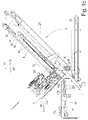
FIGS. 1 a, b: a slicing machine in the form of a slicer according to the prior art in different perspective views, -
FIG. 1 c: the slicing machine ofFIGS. 1a, b in side view, -
FIG. 2a : a simplified vertical longitudinal section through the slicing machine ofFIGS. 1a -c, i.e. in the same direction of view asFIG. 1c , in which the various conveyor belts can be seen more clearly, with the feed belt tilted up into the slicing position, -
FIG. 2b : a longitudinal section as inFIG. 2a , but with the infeed belt tilted down into the loading position and the product caliber in an advanced state of cutting, -
FIG. 3a : an enlarged detail view of a section ofFIG. 2 b, -
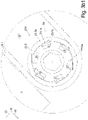
FIG. 3b 1: a detailed view of a driven lower product guide designed as a belt conveyor with a freewheel unit, which is provided for a slicing machine according to the invention, and -
FIG. 3b 2: a detailed view of a driven upper product guide embodied as a belt conveyor with a freewheel unit, which is provided for the slicing machine according to the invention. -
FIGS. 1 a, 1 b show different perspective views of aslicer 1 for simultaneous slicing of a plurality of product calibers K side by side on different tracks SP1 to SP4 and depositing in shingled portions P of several slices S each with ageneral passage direction 10* through theslicer 1 from left to right as well asFIG. 1c a side view of thisslicer 1. -
FIG. 2a shows a vertical section through such aslicer 1 inlongitudinal direction 10, the feeding direction of the calibers K to thecutting unit 7 and thus the longitudinal direction of the calibers K lying in theslicer 1, i.e., with the same viewing direction asFIG. 1 c, simplified by omitting details less important for the invention. - It can be seen that the basic structure of a
slicer 1 according to the state of the art is that acutting unit 7 with arotating sickle blade 3 is fed with a plurality of, in this case four, product calibers K lying next to each other transversely to the feedingdirection 10 by afeed unit 20, from the front ends of each of which therotating sickle blade 3 simultaneously separates a slice S. - For this purpose, the
feed unit 20 comprises afeed conveyor 4 in the form of an endless, circulatingfeed belt 4, the upper run of which can be driven at least in the feedingdirection 10 and also in opposition thereto, the calibers K lying next to one another in the width of this feed conveyor being arranged on thefeed belt 4 at a distance from one another in the feedingdirection 10 mostly by means of spacers 15 which project outwards from thefeed belt 4 with respect to the direction of circulation, i.e., upwards from the upper run. - For slicing the product calibers K, the
feed conveyor 4 is in the inclined position shown inFIGS. 1a-c and 2a with a low-lying cutting-side front end and a high-lying rear end, from which it can be tilted down into an approximately horizontal loading position about apivot axis 20′ running in its width direction, the 1sttransverse direction 11, which is located in the vicinity of thecutting unit 7. - The rear end of a caliber K—lying in the
feed unit 20 is held positively in each case by agripper 14 a-d with the aid ofgripper claws 16. Thesegrippers 14 a-14 d, which can be activated and deactivated with respect to the position of thegripper claws 16, are attached to acommon gripper unit 13, which can be fed along a rod-shapedgripper guide 18 in the feedingdirection 10. - Both the feed of the
gripper unit 13 and thefeed conveyor 4 can be driven in a controlled manner, but the specific feed speed of the calibers K is effected by a so-called upper andlower product guide - The front ends of the calibers K are each guided through a so-called
product opening 6 a-d present for each caliber, which are formed in a plate-shapedcutting frame 5, which is a component of thecutting unit 7, in that the cuttingplane 3″, in which thesickle blade 3 rotates with itscutting edge 3 a and thus cuts off the projection of the calibers K from the cuttingframe 5 as a slice S, runs directly in front of the front end face of thecutting frame 5, which points obliquely downwards. The cuttingplane 3″ runs perpendicular to the upper run of thefeed conveyor 4 and/or is spanned by the twotransverse directions - The inner circumference of the
product openings 6 a-d of thecutting edge 3 a of theblade 3 serves as a counter cutting edge. - Although the
product openings 6 a-d of thereplaceable cutting frame 5 are approximately adapted to the cross section shape and size of the calibers K to be cut on the various tracks SP1 to SP4, since their cross section size is subject to production-related fluctuations, the cross section of theproduct openings 6 a-d is generally somewhat larger than the cross section of the caliber K to be cut. - In order to nevertheless achieve a good cutting result and to be able to control parameters such as the contact force of the caliber K on the inner circumferential surface of the
spectacle opening 6 a-d and other parameters, the bottom and top product guides 8, 9, each in the form of a conveyor belt, are provided, of which thebottom product guide 9 with its upper run and thetop product guide 8 with the lower run of the corresponding conveyor belt are in frictional contact with the underside and top side of the caliber K respectively. - Since both product guides 8, 9 can be driven in a controlled manner, they determine the—continuous or clocked—feed speed of the calibers K through the cutting
frame 5. Preferably, the twoproduct guides transverse direction 11. - In addition, at least the
upper product guide 8 is displaceable in the 2.transverse direction 12—which is perpendicular to the surface of the upper run of thefeed conveyor 4 tilted up into the cutting position—for adaptation to the height H of the caliber K in this direction. Furthermore, at least one of the product guides 8, 9 can be embodied to be pivotable about one of itsdeflection rollers - The slices S, which stand at an angle in the space corresponding to the inclined position of the
feed unit 20 andcutting unit 7 during separation, fall onto adischarge unit 17 which starts below the cuttingframe 5 and runs in thepassage direction 10* and which in this case consists of a plurality ofdischarge conveyors 17 a, b, c arranged one behind the other with their upper runs approximately aligned in thepassage direction 10*, one of which can also be embodied as a weighing unit. - The slices S fall either directly onto these
discharge conveyors 17 a-c, as shown inFIGS. 1c and 2 a, or onto a packaging element resting thereon, such as a carrier carton or a flat plastic tray. - Below the
feed conveyor unit 20, there is also an approximately horizontally runningendpiece conveyor 21, likewise in the form of an endlessly circulating conveyor belt, which starts with its front end below the cuttingframe 5 and directly below or behind thedischarge unit 17 and with its upper run transports endpieces falling thereon away to the rear against thepassage direction 10*. - For this purpose, at least the
first discharge conveyor 17 a in thepassage direction 10* can be driven with its upper run counter to thepassage direction 10* so that an end piece falling thereon, for example, can be transported to the rear and fall onto the lower-lyingend piece conveyor 21. -
FIG. 3a shows an enlarged detailed view of a section ofFIG. 2b , in which the driven product guides 8, 9 embodied as belt conveyors and thegripper 14 holding the caliber K can be seen in the area of thecutting frame 5 of theslicer 1. Theupper product guide 8 can be driven by adrive unit 8* acting in the region of thedeflection roller 8 a, while thelower product guide 9 can be driven by adrive unit 9* acting in the region of thedeflection roller 9 a. - Since, as already explained with
FIGS. 1a -c, theslicer 1 is amulti-track slicer 1, theslicer 1 comprises for each track anupper product guide 8 and abottom product guide 9 arranged opposite thereto, i.e. in the firsttransverse direction 11 both a plurality of upper product guides 8 and a plurality of lower product guides 9. - If the
slicer 1 is used to cut so-called mixed portions, the blades of theslicer 1 contain calibers K of different products, such as cheese, salami, fresh sausage or the like, which are to be sliced next to each other as a shingled row. In order to achieve a slice thickness adapted to the corresponding product for each of these different calibers K, a correspondingly adapted feed speed must be achieved for each caliber K in the feedingdirection 10 to the cuttingframe 10. - The special feature according to the invention now consists in the fact that in the
slicer 1 according to the invention either only the upper product guides 8 or only the lower product guides 9 can be driven separately for each track SP1 to SP4. The other product guides 8 or 9 can only be driven together for each track SP1 to SP4, i.e., at the same speed in the feedingdirection 10. - In order to be able to achieve different feed speeds of the calibers K in the feeding
direction 10 for each track SP1 to SP4, a freewheel unit acting in the feedingdirection 10 of the calibers K is provided according to the invention in those of the product guides 8 or 9 which can only be driven together for each track, which will be described in more detail with reference toFIGS. 1 and 3 c 2.3b -
FIG. 1 shows an exemplary embodiment of a3b freewheel unit 23 a acting in the feedingdirection 10, which is formed on thelower product guide 9. Thefreewheel unit 23 a comprises locking elements 23.1 a, which are operatively connected to a belt drive unit 23.2 a of thelower product guide 9. - In the exemplary embodiment shown, the locking elements 23.1 a are pivotably mounted on the belt drive unit 23.2 a and are thereby adjustable between a locking position, in which the locking elements 23.1 a engage with a connecting part 23.3 a, which is non-rotatably connected to the
deflection roller 9 a, in such a way that a relative movement between the connecting part 23.3 a, which corresponds to an advance of the belt drive unit 23.2 a in the direction of arrow F relative to the connecting part 23.3 a, is substantially prevented, and a release position (shown in dashed lines), in which this relative movement between the belt drive unit 23.2 a and the connecting part 23.3 a, which is connected to thedeflection roller 9 a in a rotationally fixed manner, is permitted. - In other words, due to the action of the
freewheel unit 23 a, it is possible for the upper run 9.1 to move in the feedingdirection 10 at a feed speed which is slower than the feed speed of the upper run 9.1 in the feedingdirection 10 caused by the rotation of the belt drive unit 23.2 a. - Each of the locking elements 23.1 a is thereby biased into the locking position by means of a spring 23.4 a.
- However, in order to be able to retract the calibers K of all tracks SP1 to SP4 sufficiently quickly in the case of an empty cut, i.e., for example, after completion of a mixed portion mentioned at the beginning, the
freewheel 23 a acts only in the feeding direction 10 a of the calibers K, so that all calibers K can be retracted quickly by essentially the same amount against the feedingdirection 10, without any important slip caused by thefreewheel 23 a between the belt drive unit 23.2 a and the connecting part 23.3 a or thedeflection roller 9 a caused by thefreewheel 23 a. - This is achieved by preventing movement of the belt drive unit 23.2 a in the direction opposite to the direction of arrow F relative to the connecting part 23.3 a by the locking elements 23.1 a. These namely then remain in their locking position and engage in latching recesses 23.5 a, which prevent the relative movement between the drive unit 23.2 a and the connecting element 23.3 a, which is non-rotatably connected to the
deflection roller 9 a, in the opposite direction. - In contrast,
FIG. 2 shows an exemplary embodiment of a3b freewheel unit 23 b acting in the feedingdirection 10, which is formed on theupper product guide 8. - The same parts of the
freewheel unit 23 b are provided with analogous reference signs as inFIG. 1, but supplemented by the additional letter “b” instead of “a”. The function and effect of the3b freewheel unit 23 b as shown inFIG. 2 corresponds essentially to the3b freewheel unit 23 a inFIG. 1, the description of which is hereby expressly referred to.3b -
-
- 1 slicing machine, slicer
- 1* control
- 2 base frame
- 3 blade, sickle blade
- 3 rotation axis
- 3″ blade plane, cutting plane
- 3 a cutting edge
- 4 feed conveyor, feed belt
- 5 cutting frame
- 6 a-d product opening
- 7 cutting unit
- 8 upper product guide, upper guide belt
- 8.1 contact run, lower run
- 8 a cutting side deflection roller
- 8 b deflection roller facing away from the cutting side
- 9 bottom product guide, lower guide belt
- 9.1 contact run, upper run
- 9 a cutting side deflection roller
- 9 b deflection roller facing away from the cutting side
- 10 feed direction, longitudinal direction, axial direction,
- 10* pass through direction
- 11 1. transverse direction (width slicer)
- 12 2. transverse direction (height-direction caliber)
- 13 gripper unit, gripper slide
- 14, 14 a-d gripper
- 15 spacer
- 15′ support surface
- 16 gripper claw
- 17 discharge conveyor unit
- 17 a, b, c portioning belt, discharge conveyor
- 18 gripper guide
- 19 height sensor
- 20 feed unit
- 21 end piece conveyor
- 22 end piece container
- 23 a, b freewheel unit
- 23.1 a, 23.1 b locking element
- 23.2 a, 23.2 b drive unit, belt drive unit
- 23.3 a, 23.3 b connecting part
- 23.4 a, 23.4 b spring
- 23.5 a, 23.5 b latching recesses
- K product, product caliber
- Kr end piece
- S slice
- P portion
- V packaging element
Claims (14)
Applications Claiming Priority (2)
| Application Number | Priority Date | Filing Date | Title |
|---|---|---|---|
| DE102020133162.2A DE102020133162A1 (en) | 2020-12-11 | 2020-12-11 | slicing machine |
| DE102020133162.2 | 2020-12-11 |
Publications (1)
| Publication Number | Publication Date |
|---|---|
| US20220184838A1 true US20220184838A1 (en) | 2022-06-16 |
Family
ID=81750321
Family Applications (1)
| Application Number | Title | Priority Date | Filing Date |
|---|---|---|---|
| US17/547,924 Abandoned US20220184838A1 (en) | 2020-12-11 | 2021-12-10 | Slicing machine |
Country Status (2)
| Country | Link |
|---|---|
| US (1) | US20220184838A1 (en) |
| DE (1) | DE102020133162A1 (en) |
Families Citing this family (1)
| Publication number | Priority date | Publication date | Assignee | Title |
|---|---|---|---|---|
| DE102023103039A1 (en) * | 2023-02-08 | 2024-08-08 | Multivac Sepp Haggenmüller Se & Co. Kg | Slicing machine |
Citations (4)
| Publication number | Priority date | Publication date | Assignee | Title |
|---|---|---|---|---|
| US4872548A (en) * | 1986-06-05 | 1989-10-10 | Otsuka Koki Kabushiki Kaisha | Intermittently-driven belt conveyor |
| US20140174891A1 (en) * | 2012-12-03 | 2014-06-26 | Textor Maschinenbau GmbH | High Performance Slicing Apparatus With At Least One Removable Conveyor Belt Unit |
| US20150321372A1 (en) * | 2014-05-07 | 2015-11-12 | Formax, Inc | Food product slicing apparatus and methods associated with the same |
| US20180186576A1 (en) * | 2017-01-04 | 2018-07-05 | Provisur Technologies, Inc. | Configurable In-Feed for a Food Processing Machine |
Family Cites Families (3)
| Publication number | Priority date | Publication date | Assignee | Title |
|---|---|---|---|---|
| DE102009023751A1 (en) | 2009-06-03 | 2010-12-16 | Weber Maschinenbau Gmbh Breidenbach | Apparatus and method for slicing food products |
| DE102009023729A1 (en) | 2009-06-03 | 2010-12-09 | Weber Maschinenbau Gmbh Breidenbach | Apparatus and method for slicing food products |
| DE102015110534A1 (en) | 2015-06-30 | 2017-01-05 | Weber Maschinenbau Gmbh Breidenbach | feeder |
-
2020
- 2020-12-11 DE DE102020133162.2A patent/DE102020133162A1/en active Pending
-
2021
- 2021-12-10 US US17/547,924 patent/US20220184838A1/en not_active Abandoned
Patent Citations (4)
| Publication number | Priority date | Publication date | Assignee | Title |
|---|---|---|---|---|
| US4872548A (en) * | 1986-06-05 | 1989-10-10 | Otsuka Koki Kabushiki Kaisha | Intermittently-driven belt conveyor |
| US20140174891A1 (en) * | 2012-12-03 | 2014-06-26 | Textor Maschinenbau GmbH | High Performance Slicing Apparatus With At Least One Removable Conveyor Belt Unit |
| US20150321372A1 (en) * | 2014-05-07 | 2015-11-12 | Formax, Inc | Food product slicing apparatus and methods associated with the same |
| US20180186576A1 (en) * | 2017-01-04 | 2018-07-05 | Provisur Technologies, Inc. | Configurable In-Feed for a Food Processing Machine |
Also Published As
| Publication number | Publication date |
|---|---|
| DE102020133162A1 (en) | 2022-06-15 |
Similar Documents
| Publication | Publication Date | Title |
|---|---|---|
| US20220241999A1 (en) | Method for folding a cut slice and slicing machine designed for this purpose | |
| US11945132B2 (en) | Multi-track slicing machine with independently controllable grippers | |
| US12454380B2 (en) | Method of operating a packaging line and packaging line suitable therefor | |
| CA2749968C (en) | D-cut slicer | |
| US11718484B2 (en) | Method for transversely positioning an article to be transported | |
| US12227367B2 (en) | Feeding of food products in slicing or portioning machines | |
| US20230390954A1 (en) | Blade, cutting unit and slicing machine | |
| US12492081B2 (en) | Method for positioning an article to be transported and device for carrying out the method | |
| US20220184838A1 (en) | Slicing machine | |
| US11685071B2 (en) | Slicing machine | |
| US12441504B2 (en) | Method for automatically maintaining a predetermined portion arrangement in a tray, packaging device suitable therefor | |
| US20250073938A1 (en) | Slicing machine, in particular slicer, and method | |
| US12053899B2 (en) | Slicing machine | |
| US20240335969A1 (en) | Slicing machine and method for slicing product calibres | |
| US20240261995A1 (en) | Slicing machine | |
| US12311568B2 (en) | Method for the parallel production of shingled portions with different number of slices and suitable slicing machine | |
| US20250222614A1 (en) | Slicing machine and method for slicing foods | |
| US12064891B2 (en) | Slicing machine | |
| US20250332752A1 (en) | Slicing machine and method for slicing foodstuffs | |
| JP5759327B2 (en) | Bread bread conveying method and apparatus in bread slicer | |
| JP3752619B2 (en) | Slicer transfer device | |
| JP4381056B2 (en) | Guide device for slice pieces in meat slicer | |
| JP2702457B2 (en) | Food slicer |
Legal Events
| Date | Code | Title | Description |
|---|---|---|---|
| AS | Assignment |
Owner name: MULTIVAC SEPP HAGGENMUELLER SE & CO. KG, GERMANY Free format text: ASSIGNMENT OF ASSIGNORS INTEREST;ASSIGNOR:ERTL, JOCHEN;REEL/FRAME:058362/0869 Effective date: 20211206 |
|
| STPP | Information on status: patent application and granting procedure in general |
Free format text: DOCKETED NEW CASE - READY FOR EXAMINATION |
|
| STPP | Information on status: patent application and granting procedure in general |
Free format text: NON FINAL ACTION MAILED |
|
| STPP | Information on status: patent application and granting procedure in general |
Free format text: RESPONSE TO NON-FINAL OFFICE ACTION ENTERED AND FORWARDED TO EXAMINER |
|
| STPP | Information on status: patent application and granting procedure in general |
Free format text: FINAL REJECTION MAILED |
|
| STCB | Information on status: application discontinuation |
Free format text: ABANDONED -- FAILURE TO RESPOND TO AN OFFICE ACTION |