EP3961884A1 - Supraleitende induktionsrotationsmaschine und supraleitende antriebskrafterzeugungsanlage mit dieser supraleitenden induktionsrotationsmaschine - Google Patents
Supraleitende induktionsrotationsmaschine und supraleitende antriebskrafterzeugungsanlage mit dieser supraleitenden induktionsrotationsmaschine Download PDFInfo
- Publication number
- EP3961884A1 EP3961884A1 EP20793982.8A EP20793982A EP3961884A1 EP 3961884 A1 EP3961884 A1 EP 3961884A1 EP 20793982 A EP20793982 A EP 20793982A EP 3961884 A1 EP3961884 A1 EP 3961884A1
- Authority
- EP
- European Patent Office
- Prior art keywords
- superconducting
- rotor
- rotating machine
- stator
- induction rotating
- Prior art date
- Legal status (The legal status is an assumption and is not a legal conclusion. Google has not performed a legal analysis and makes no representation as to the accuracy of the status listed.)
- Pending
Links
Images





Classifications
-
- H—ELECTRICITY
- H02—GENERATION; CONVERSION OR DISTRIBUTION OF ELECTRIC POWER
- H02K—DYNAMO-ELECTRIC MACHINES
- H02K55/00—Dynamo-electric machines having windings operating at cryogenic temperatures
-
- B—PERFORMING OPERATIONS; TRANSPORTING
- B64—AIRCRAFT; AVIATION; COSMONAUTICS
- B64D—EQUIPMENT FOR FITTING IN OR TO AIRCRAFT; FLIGHT SUITS; PARACHUTES; ARRANGEMENT OR MOUNTING OF POWER PLANTS OR PROPULSION TRANSMISSIONS IN AIRCRAFT
- B64D27/00—Arrangement or mounting of power plants in aircraft; Aircraft characterised by the type or position of power plants
- B64D27/02—Aircraft characterised by the type or position of power plants
- B64D27/30—Aircraft characterised by electric power plants
-
- B—PERFORMING OPERATIONS; TRANSPORTING
- B64—AIRCRAFT; AVIATION; COSMONAUTICS
- B64D—EQUIPMENT FOR FITTING IN OR TO AIRCRAFT; FLIGHT SUITS; PARACHUTES; ARRANGEMENT OR MOUNTING OF POWER PLANTS OR PROPULSION TRANSMISSIONS IN AIRCRAFT
- B64D27/00—Arrangement or mounting of power plants in aircraft; Aircraft characterised by the type or position of power plants
- B64D27/02—Aircraft characterised by the type or position of power plants
- B64D27/30—Aircraft characterised by electric power plants
- B64D27/33—Hybrid electric aircraft
-
- H—ELECTRICITY
- H01—ELECTRIC ELEMENTS
- H01F—MAGNETS; INDUCTANCES; TRANSFORMERS; SELECTION OF MATERIALS FOR THEIR MAGNETIC PROPERTIES
- H01F6/00—Superconducting magnets; Superconducting coils
- H01F6/04—Cooling
-
- H—ELECTRICITY
- H01—ELECTRIC ELEMENTS
- H01F—MAGNETS; INDUCTANCES; TRANSFORMERS; SELECTION OF MATERIALS FOR THEIR MAGNETIC PROPERTIES
- H01F6/00—Superconducting magnets; Superconducting coils
- H01F6/06—Coils, e.g. winding, insulating, terminating or casing arrangements therefor
-
- H—ELECTRICITY
- H02—GENERATION; CONVERSION OR DISTRIBUTION OF ELECTRIC POWER
- H02K—DYNAMO-ELECTRIC MACHINES
- H02K1/00—Details of the magnetic circuit
- H02K1/06—Details of the magnetic circuit characterised by the shape, form or construction
- H02K1/12—Stationary parts of the magnetic circuit
- H02K1/16—Stator cores with slots for windings
-
- H—ELECTRICITY
- H02—GENERATION; CONVERSION OR DISTRIBUTION OF ELECTRIC POWER
- H02K—DYNAMO-ELECTRIC MACHINES
- H02K1/00—Details of the magnetic circuit
- H02K1/06—Details of the magnetic circuit characterised by the shape, form or construction
- H02K1/22—Rotating parts of the magnetic circuit
- H02K1/26—Rotor cores with slots for windings
-
- H—ELECTRICITY
- H02—GENERATION; CONVERSION OR DISTRIBUTION OF ELECTRIC POWER
- H02K—DYNAMO-ELECTRIC MACHINES
- H02K17/00—Asynchronous induction motors; Asynchronous induction generators
- H02K17/02—Asynchronous induction motors
- H02K17/16—Asynchronous induction motors having rotors with internally short-circuited windings, e.g. cage rotors
-
- H—ELECTRICITY
- H02—GENERATION; CONVERSION OR DISTRIBUTION OF ELECTRIC POWER
- H02K—DYNAMO-ELECTRIC MACHINES
- H02K21/00—Synchronous motors having permanent magnets; Synchronous generators having permanent magnets
- H02K21/12—Synchronous motors having permanent magnets; Synchronous generators having permanent magnets with stationary armatures and rotating magnets
- H02K21/22—Synchronous motors having permanent magnets; Synchronous generators having permanent magnets with stationary armatures and rotating magnets with magnets rotating around the armatures, e.g. flywheel magnetos
-
- H—ELECTRICITY
- H02—GENERATION; CONVERSION OR DISTRIBUTION OF ELECTRIC POWER
- H02K—DYNAMO-ELECTRIC MACHINES
- H02K3/00—Details of windings
- H02K3/02—Windings characterised by the conductor material
-
- H—ELECTRICITY
- H02—GENERATION; CONVERSION OR DISTRIBUTION OF ELECTRIC POWER
- H02K—DYNAMO-ELECTRIC MACHINES
- H02K7/00—Arrangements for handling mechanical energy structurally associated with dynamo-electric machines, e.g. structural association with mechanical driving motors or auxiliary dynamo-electric machines
- H02K7/14—Structural association with mechanical loads, e.g. with hand-held machine tools or fans
-
- H—ELECTRICITY
- H02—GENERATION; CONVERSION OR DISTRIBUTION OF ELECTRIC POWER
- H02K—DYNAMO-ELECTRIC MACHINES
- H02K9/00—Arrangements for cooling or ventilating
- H02K9/19—Arrangements for cooling or ventilating for machines with closed casing and closed-circuit cooling using a liquid cooling medium, e.g. oil
- H02K9/193—Arrangements for cooling or ventilating for machines with closed casing and closed-circuit cooling using a liquid cooling medium, e.g. oil with provision for replenishing the cooling medium; with means for preventing leakage of the cooling medium
-
- H—ELECTRICITY
- H02—GENERATION; CONVERSION OR DISTRIBUTION OF ELECTRIC POWER
- H02K—DYNAMO-ELECTRIC MACHINES
- H02K9/00—Arrangements for cooling or ventilating
- H02K9/22—Arrangements for cooling or ventilating by solid heat conducting material embedded in, or arranged in contact with, the stator or rotor, e.g. heat bridges
- H02K9/227—Heat sinks
-
- H—ELECTRICITY
- H02—GENERATION; CONVERSION OR DISTRIBUTION OF ELECTRIC POWER
- H02K—DYNAMO-ELECTRIC MACHINES
- H02K2213/00—Specific aspects, not otherwise provided for and not covered by codes H02K2201/00 - H02K2211/00
- H02K2213/03—Machines characterised by numerical values, ranges, mathematical expressions or similar information
-
- Y—GENERAL TAGGING OF NEW TECHNOLOGICAL DEVELOPMENTS; GENERAL TAGGING OF CROSS-SECTIONAL TECHNOLOGIES SPANNING OVER SEVERAL SECTIONS OF THE IPC; TECHNICAL SUBJECTS COVERED BY FORMER USPC CROSS-REFERENCE ART COLLECTIONS [XRACs] AND DIGESTS
- Y02—TECHNOLOGIES OR APPLICATIONS FOR MITIGATION OR ADAPTATION AGAINST CLIMATE CHANGE
- Y02E—REDUCTION OF GREENHOUSE GAS [GHG] EMISSIONS, RELATED TO ENERGY GENERATION, TRANSMISSION OR DISTRIBUTION
- Y02E40/00—Technologies for an efficient electrical power generation, transmission or distribution
- Y02E40/60—Superconducting electric elements or equipment; Power systems integrating superconducting elements or equipment
-
- Y—GENERAL TAGGING OF NEW TECHNOLOGICAL DEVELOPMENTS; GENERAL TAGGING OF CROSS-SECTIONAL TECHNOLOGIES SPANNING OVER SEVERAL SECTIONS OF THE IPC; TECHNICAL SUBJECTS COVERED BY FORMER USPC CROSS-REFERENCE ART COLLECTIONS [XRACs] AND DIGESTS
- Y10—TECHNICAL SUBJECTS COVERED BY FORMER USPC
- Y10S—TECHNICAL SUBJECTS COVERED BY FORMER USPC CROSS-REFERENCE ART COLLECTIONS [XRACs] AND DIGESTS
- Y10S505/00—Superconductor technology: apparatus, material, process
- Y10S505/825—Apparatus per se, device per se, or process of making or operating same
- Y10S505/876—Electrical generator or motor structure
Definitions
- the present invention relates to an induction rotating machine and a superconducting driving force generation system using the same.
- an electric motor of Patent Document 1 has a rotor constructed with a laminated body of a high-temperature superconductor and a torque shield made of a normal conducting material, wherein upon activation at a room temperature, a rotating machine is activated in an induction mode by applying an alternating magnetic field (rotating magnetic field) generated by energizing armature coils (primary winding) arranged in a stator to thereby induce a torque generated by an interaction between an electric current induced in the torque shield and the alternating magnetic field, wherein once the rotor activates and reaches a predetermined rotation speed, the rotor is rotated synchronously by cooling the superconductor to its superconducting state at its critical temperature or lower, and causing the superconductor to use its magnetic flux to capture the alternating magnetic field.
- alternating magnetic field rotating magnetic field
- armature coils primary winding
- This superconducting induction rotating machine may be operated without externally supplying the electric power to the rotor to enable simplification of this machine's structure.
- transition from the induction mode to a synchronous operation requires determining the critical temperature of the superconductor and cooling the superconductor to the critical temperature or lower, which temperature control process takes a relatively long time, possibly reducing this electric motor's operational responsiveness. For this reason, in rotating machines used for applications where the machines are frequently and repeatedly activated and stopped as in electric vehicles, for example, significant joule heat (copper loss) is considered to occur in the torque shield, making it difficult to maintain the superconductor at or below the critical temperature, causing the decline of the rotating machine efficiency due to the increase of the copper loss itself.
- Patent Document 2 proposes an electric motor for addressing the inherent problem in Patent Document 1.
- a superconducting induction rotating machine of Patent Document 2 provides a structure which houses a combination of a rotor core of a squirrel-cage induction rotating machine, normal conducting squirrel-cage winding of rotor bars made of normal conducting wires with end rings connected with both ends of the rotor bars, respectively, and superconducting squirrel-cage winding of rotor bars made of superconducting conducting wires connected with end rings, wherein this combination is housed in slots formed in the circumferential surface of the rotor core.
- this electric motor In the normal conducting state, this electric motor may be activated and operated mainly by the torque generated by the interaction between the electric current induced in the normal conducting squirrel-cage winding and the rotating magnetic field generated by energizing the armature coils arranged in a stator, whereas, in the superconducting state, this electric motor may be operated independent of the superconductor critical temperature by the superconducting squirrel-cage winding which captures the magnetic flux of the rotating magnetic field applied by the armature coils of the stator to thereby achieve the synchronous operation.
- the electric motor of Patent Document 2 has the following challenges in its practical applications. That is, since the electric motor of Patent Document 2 is configured with the rotor core having the squirrel-cage rotor configured with both the normal conducting squirrel-cage winding and the superconducting squirrel-cage winding, when activating the rotating machine at a room temperature equal to or above the critical temperature of the superconducting squirrel-cage winding, large joule heat or copper loss occurs due to the induced electric current in the normal conducting squirrel-cage winding as in the torque shield of the superconducting rotating machine of Patent Document 1. Also, for the superconducting squirrel-cage winding, its winding structure becomes complex due to the required electric connections between both ends of the rotor bars and the end rings of the structure.
- Patent Document 3 discloses a novel superconducting rotating machine, which requires no supply of external electric power to a superconductor incorporated in a rotor, wherein the rotor is not provided with a torque shield of Patent Document 1, any normal conducting metal body as a joule heating source, such as normal conducting squirrel-cage winding of Patent Document 2, or a heavy rotor core, and wherein the superconducting rotating machine is configured to take advantage of superconducting characteristics of the superconductor with ingenuity such that the size and weight reduction of the superconducting rotating machine as well as its high-efficiency rotation performance may be achieved.
- the superconducting rotating machine of Patent Document 3 is equipped with an armature coil provided on the stator side, and a superconducting rotor having a plate-like superconductor, and the superconducting rotating machine is configured to cause the superconducting rotor to generate a rotating force based on an electromagnetic force produced by an interaction between a shielding current induced in the plate-like superconductor due to a magnetic field that the armature coil applies to the superconductor, and the magnetic field.
- the superconducting rotor having the plate-like superconductor contributes to reducing the rotor size and weight, it was difficult to improve the torque for imparting the rotational force to the superconducting rotor.
- the purpose of the present invention is to provide a superconducting induction rotating machine which is more compact, and capable of operating with less electric power and generating a driving force very efficiently.
- Another object of the invention is to provide a superconducting induction rotating machine which has a simple structure, and is widely applicable as a propulsion generation system.
- rotor may be configured with a thin and light-weight cylindrical body, and a superconducting induction rotating machine with high efficiency and high output may be provided.
- a rotor may be configured with a simple cylindrical body having no windings and the like, and the entire structure may have reduced size and weight to provide a rotating machine which is inexpensive as well as highly durable and reliable.
- propulsion generation body or bodies such as fins, propellers, tires or the like may be directly attached, for example, on an inner surface or an outer surface of the cylindrical body to thereby provide a propulsion generation system with a simple structure and a reduced driving force transmission loss.
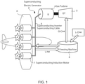
- Fig. 1 is a schematic view showing a structural concept of a fully superconducting system 2, which includes a superconducting induction motor 1 according to the present embodiment.
- This system 2 has a basically high-efficient gas turbine engine 3, a superconducting electric generator 4, a superconducting inverter/superconducting cable 5 and the superconducting induction motor 1.
- This system 2 uses LNG or liquid hydrogen, having a refrigerant function, as a fuel for the gas turbine engine 3, and liquid nitrogen as a refrigerant for cooling a superconductor. Also, the system 2 is configured to be capable of suppressing overall electric power consumption by processing the above fuel and refrigerant with a common freezing machine 6.
- this fully superconducting system 2 connects the electric generator 4, the superconducting inverter/cable 5 and the superconducting induction motor 1 without exposing them to a room temperature to thereby integrate a common refrigerant flow channel for cooling them.
- the system 2 is configured so that it may further decrease a refrigerant load to allow reduction of the electric power consumption.
- each motor may be independently controlled for steering in up, down, left and right directions.
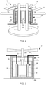
- Fig. 2 shows a conceptual diagram of a demonstration system 10 of an outer rotor-type motor 1' as a superconducting induction motor 1 used for the fully superconducting system 2.
- This demonstration system 10 is configured to validate if enough output may be obtained from the superconducting induction motor 1', and if enough output is obtained, the demonstration system 10 is configured so that it may be driven upward (indicated with an arrow B) by propeller blades 11 attached to the rotor to thereby levitate.
- a base Indicated with 12 in Fig. 2 is a base.
- This base 12 is formed in a disc shape, and provided on its central top side are a pair of pole-shaped linear guides 13 standing in parallel and spaced apart by a certain distance. These linear guides 13 act as vertical guides for the induction motor 1' when the outer rotor-type induction motor 1' is driven upward (arrow B) by propulsion of the propeller blades 11.
- a stator 14 is retained on the linear guides 13 slidably in an up-down direction.
- This stator 14 is formed of a cylindrical member with its top and bottom openings being closed, and a superconducting armature coil 15 is disposed on the inner surface of an outer circumferential wall section of the stator 14.
- This stator 14 has a structure of a vacuum container having a predetermined degree of vacuum (e.g., from about 10-5 to about 10-6 Torr) in order to maintain a cooling temperature of the superconducting armature coil 15.
- the superconducting armature coil 15 is connected to a power supply lead 17 for supplying electric power from the electric generator 4 ( Fig. 1 ), and the power supply lead 17 is guided out of the stator 14 from its bottom.
- a rotor 18 having a cylindrical main body is externally fitted over the stator 14 with a gap of a predetermined dimension between the rotor 18 and the stator 14. Between the rotor 18 and the stator 14 at the top and bottom ends thereof, bearings indicated with 19, 20 are inserted.
- This rotor 18 is constituted with a complex with small thickness consisting of a highly electrically conductive material layer 22 consisting of a highly conductive nonmagnetic material, such as copper, aluminum or the like, disposed on a surface opposing the stator 14; and a magnetic material layer 23 consisting of highly magnetically permeable iron or the like for returning magnetic flux, which magnetic material layer 23 disposed of immediately outside of the highly electrically conductive material layer 22, wherein the rotor 18 has an extremely light weight construction.
- magnetic flux intersecting the highly electrically conductive material layer 22 is increased by the magnetic material layer 23, facilitating an increase of induced current in the highly electrically conductive material layer, and therefore, an increase of torque.
- the propeller blades 11 are provided on the outer circumferential surface of this rotor 18.
- a base section 11a of each of the propeller blades 11 is secured by welding, and distal ends 11b of the propeller blades 11 extending outward along diametrical directions of the rotor 18 are provided around periphery of this rotor 18 at regular intervals.
- the rotor 18 may be rotationally driven by a rotational torque in the rotor 18 generated by a rotating magnetic field created by the armature coils 15. This in turn rotate the propeller blades 11 in a direction indicated with an arrow C to thereby allow the induction motor 1' to levitate.
- the present inventors confirmed that an effective output efficiency is obtained through demonstration experiments such as ones related to the above problem, and continued other experiments to complete the present invention.
- Fig. 3 is a schematic view showing an inner rotor-type superconducting induction motor 1".
- This induction motor 1 comprises a stator frame 26; a stator 28 secured to the stator frame 26 for maintaining superconducting armature coils 27 thereon; a power supply lead 29 connected to the top of the armature coils 27 for feeding them electricity; a rotor 30 rotationally retained about an vertical axis and facing the inner surface of the coils 27; a central axis 31 extending upward from the rotor 30 to above the stator 28 and rotationally retained in the center of top wall of the stator frame 26; and propeller blades 32 provided at the top end of the central axis 31.
- the stator frame 26 is formed of any material, preferably a material with a thermally-insulating function.
- This stator frame 16 comprises a cylindrical (or rectangular) outer circumferential wall 26a as well as a top wall section 26b and a bottom wall section 26c for closing an upper opening and a lower opening of the outer circumferential wall 26a.
- a container 33 is secured inside this stator frame 26, a container 33 is secured for retaining liquid nitrogen.
- This stator frame 26 is adapted to have a structure of vacuum space of a predetermined degree of vacuum (e.g., from about 10-5 to about 10-6 Torr) in order to maintain a cooling temperature of the superconductor filling the armature coil 33.
- the container 33 is formed of a material which is an electric insulator generating no eddy current loss and having mechanical strength at a low temperature, such as a FRP.
- this material is not limited to FRPs and may be of other materials having similar characteristics.
- Fig. 4 shows a top view of the stator 28 secured to the container 33 in the stator frame 26; and Fig. 5 shows a perspective view of the stator 28.
- the stator28 comprises a cylindrical main body 35 and superconducting armature coils 36 attached to the main body 35.
- the main body 35 is formed of a FRP and, as shown in Fig. 4 , its cross section has a shape having a hexagonal profile and having a central cylindrical through-hole.
- an inner circumferential surface of this main body 35 is formed in a tubular shape having a certain diameter, and an outer circumferential surface of this main body 35 is formed to be divided into six rectangular sides in its circumferential direction.
- one superconducting armature coil 36 is secured to each of the six rectangular sides, and therefore, six superconducting armature coils 36 in total are secured along the outer circumference of the main body 35.
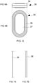
- Fig. 6 shows a top view ( Fig. 6A ) and a plan view ( Fig. 6B ) of one of the superconducting armature coils 36.
- Each of the superconducting armature coils 36 of this embodiment example does not use a core made of a material with high magnetic permeability such as iron, but is constructed only with a FRP core 37 and a superconducting coiling wire 38 wound around the FRP core 37, thus enabling this structure to increase its magnetic flux density.
- the superconducting coiling wire 38 is, as shown in Fig. 7 (Fig. 7A, Fig. 7B ), a thin and narrow ribbon-like RE-based (yttrium-based) high-temperature superconducting wire.
- the superconducting wire is not limited to the above shape and material, and other superconducting wires, such as bismuth-based superconducting materials may be used.
- the stator 28 with the superconducting armature coils 36 attached thereto is secured in the central section of the container 33, as shown in Fig. 3 .
- the container 33 is filled with a refrigerant, and the superconducting armature coils 36 are cooled using refrigerant immersion cooling.
- armature coils 36 may be connected in series or in parallel.
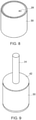
- the rotor 30 disposed inside the inner diameter of the stator 28 is a cylindrical member, as shown in Fig. 8 , and has an outer diameter smaller than the inner diameter of the stator 28 (main body 35).
- this rotor 30 is constituted with a complex consisting of an electrically conductive material layer 39 of aluminum, copper or the like, disposed on a surface opposing the stator 14; and a magnetic material layer 40 with high magnetic permeability for returning magnetic flux, which magnetic material layer 40 laminated on an inner surface of the electrically conductive material layer 39, wherein the rotor 30 has an extremely light weight construction.
- lid bodies 42, 43 are attached at the top and bottom of the rotor 30, respectively, and the central axis 31 is inserted vertically through these lid bodies 42, 43 and the rotor 30 along the central axis of the rotor 30.
- Fig. 10 is a schematic view showing an inner rotor-type induction motor unit assembled by inserting the rotor 30 into the stator 28.
- the above stator 28 of the inner rotor-type induction motor 1" was an example where six armature coils were attached on the outer surface of the main body 35, but the present invention is not limited by this configuration.
- a main body 35' is larger than the main body 35, and 12 armature coils 36' are secured on an inner surface side of the main body 35'. According to such a configuration, larger output may be obtained.
- stator 28 side was made to be superconductive while the rotor 30 was not and configured as a light cylindrical body, but if a rotor indicated with 30' below is used as in Fig. 12 , the rotor 30 may be made superconductive while keeping the operation effect of the present invention to enable higher efficiency and output of the induction motor.
- the rotor 30' comprises superconducting wires 45 embedded vertically in an electrically conductive material layer 39' (a layer formed of copper) on an outer side of the rotor 30', and short-circuit rings 46, 47 attached at the top and bottom, respectively, to connect the superconducting wires 45.
- the embedding of the superconducting wires 45 into the rotor 30' may improve the shielding current density (increase shielding current) induced by the magnetic flux linking to the rotor 30', and even when a rotor 30' has a small thickness, it may induce a large current. Accordingly, the torque increases to thereby enable an improved output density of the superconducting induction motor.
- the superconducting wires 45 are respectively fitted in grooves 39a provided in an electrically conductive material layer 39' made of copper, and the grooves are curved in one direction at their tops and bottoms.
- the shielding current may be configured to flow in loops, and characteristic degradation (decline of a critical current value) of the superconducting wires may be prevented.
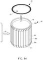
- Fig. 12 and Fig. 13 are diagrams respectively illustrating a structure of and steps for assembling the electrically conductive material layer 39' having the grooves 39a.
- the rotor (electrically conductive material layer 39') is by separately shaping and assembling ring-shaped parts 50, 51 having curved grooves 39b, 39c, and a part 52 structuring a midsection.
- the depth direction of the grooves 39a-39c is adapted to provide a slightly angled or skewed relative to the radial direction. They are configured to be capable of suppressing harmonic wave torques, electromagnetic excitation force.
- the rotor 30' is completed by fitting the ribbon-shaped superconducting wires 45 into the grooves 39a-39c, with each of the upper and lower ends of the superconducting wires 45 curved to fit the shape of the grooves 39a-39c, and then, attaching the short-circuit rings 46, 47 onto the upper and lower ends.
- each of the short-circuit rings 46, 47 is configured in a ring shape by winding a ribbon-shaped superconducting wire 53 in a horizontal direction along a circumference of each copper ring 52 having the same thickness as a width of the wire 45 so that the short-circuit rings 46, 47 respectively have the same width as the thickness of the main body.
- the superconducting wire does not need to be embedded into the rotor, but may be affixed to the surface of the rotor.
- the superconducting wires are arranged in a mesh-like manner with some of the superconducting wires provided in a circumferential direction intersecting with the others provided in a direction parallel to a central axis line, and that the superconducting wires are provided at predetermined intervals to thereby cover the entire surface of the electrically conductive material layer of the rotor.
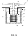
- Fig. 16 shows an example of a superconducting induction rotating machine of the present invention applied to a liquid feed pump for liquid nitrogen or liquid hydrogen.
- the liquid feed pump 55 of this embodiment is disposed in the midsection of a liquid feed pipe 56.
- a stator 57 of an induction rotating machine as the liquid feed pump 55 is secured to the liquid feed pipe 56, and a cylindrical rotor 58 is disposed in the liquid feed pipe, and is retained by the rotor 57 through bearings, which is not shown, while opposing superconducting armature coils 59.
- the rotor 58 is formed as a complex in a similar manner to that of the aforementioned embodiments, but is configured in such a way that a liquid flows through the liquid feed pipe inside an inner diameter section of the rotor 58. Also, propeller fins 60 are secured in the inner diameter section of this rotor 58.
- This example is configured so that liquid nitrogen flowing inside the liquid feed pipe 56 is used to cool the superconducting armature coil 59.
- the structure of the stator of the induction motor may be simplified.
- liquid feed pipe 56 when the liquid feed pipe 56 is long, a plurality of the liquid feed pumps 55 are disposed at predetermined intervals. In this case, since the refrigerant flowing through the liquid feed pipe is used to cool the superconducting armature coil 59, there is no need to provide additional means for cooling.
- Fig. 17 shows an example incorporating the superconducting induction motor of the present invention into a compact passenger vehicle.
- a configuration of this case uses outer rotor-type superconducting induction motors 1' similar to the one shown in Fig. 2 , and tires (tread bodies) 61 are directly attached to outer circumferential surfaces of a rotor 18, as shown in Fig. 17 .
- tires (tread bodies) 61 may be configured.
- a passenger vehicle 62 with a plurality of the tires 61 attached thereto compact mobility with a very simple configuration may be provided.
- an induction rotating machine of this embodiment may drive and feed liquid through liquid feed pipes.
- the system shown in Fig. 1 was applied to an aircraft in the above one embodiment, it is not limited to these examples and may be applied to any objects requiring propulsion.
- the system may be applied to a passenger vehicle ( Fig. 17 ) or a train.
- any means for generating propulsion by rotation of a rotor may be used.
- any configurations for increasing surface areas may be used, such as a honeycomb structure.
- the present invention when transmitting a driving force of the superconducting induction motor of the present invention by contacting with an object such as the ground, the present invention is no limited to using tires, as shown in Fig. 17 , and caterpillars or gears may be attached as propulsion generation bodies.
Landscapes
- Engineering & Computer Science (AREA)
- Power Engineering (AREA)
- Aviation & Aerospace Engineering (AREA)
- Superconductive Dynamoelectric Machines (AREA)
Applications Claiming Priority (2)
| Application Number | Priority Date | Filing Date | Title |
|---|---|---|---|
| US201962838061P | 2019-04-24 | 2019-04-24 | |
| PCT/JP2020/017730 WO2020218525A1 (ja) | 2019-04-24 | 2020-04-24 | 超伝導誘導回転機及びそれを用いた超伝導駆動力発生システム |
Publications (2)
| Publication Number | Publication Date |
|---|---|
| EP3961884A1 true EP3961884A1 (de) | 2022-03-02 |
| EP3961884A4 EP3961884A4 (de) | 2023-05-10 |
Family
ID=72940926
Family Applications (1)
| Application Number | Title | Priority Date | Filing Date |
|---|---|---|---|
| EP20793982.8A Pending EP3961884A4 (de) | 2019-04-24 | 2020-04-24 | Supraleitende induktionsrotationsmaschine und supraleitende antriebskrafterzeugungsanlage mit dieser supraleitenden induktionsrotationsmaschine |
Country Status (6)
| Country | Link |
|---|---|
| US (1) | US12184153B2 (de) |
| EP (1) | EP3961884A4 (de) |
| JP (1) | JP7560814B2 (de) |
| KR (1) | KR102831915B1 (de) |
| CN (1) | CN113785480A (de) |
| WO (1) | WO2020218525A1 (de) |
Cited By (1)
| Publication number | Priority date | Publication date | Assignee | Title |
|---|---|---|---|---|
| DE102023115683A1 (de) * | 2023-06-15 | 2024-12-19 | Karlsruher Institut für Technologie, Körperschaft des öffentlichen Rechts | Pumpe |
Families Citing this family (8)
| Publication number | Priority date | Publication date | Assignee | Title |
|---|---|---|---|---|
| GB201817883D0 (en) * | 2018-09-18 | 2018-12-19 | Rolls Royce Plc | Electric machine |
| KR102831915B1 (ko) * | 2019-04-24 | 2025-07-08 | 고쿠리쓰다이가쿠호진 규슈다이가쿠 | 초전도 유도 회전기 및 그것을 사용한 초전도 구동력 발생 시스템 |
| US12334253B2 (en) * | 2021-06-04 | 2025-06-17 | Florida State University | Systems and methods for leadless power coupling for cryogenic environments |
| CN113746299B (zh) * | 2021-09-03 | 2022-09-30 | 中国科学院电工研究所 | 一种超导转子驱动装置及其驱动方法 |
| JP7724526B2 (ja) * | 2021-09-10 | 2025-08-18 | 国立大学法人京都大学 | 超電導回転機、並びに、これを用いた船舶、自動車、航空機及びポンプ |
| CN114496480B (zh) * | 2021-12-29 | 2025-06-20 | 江苏伟正电气科技有限公司 | 一种多向降温结构及变压器散热装置 |
| CN115765385A (zh) * | 2022-11-17 | 2023-03-07 | 广东电网有限责任公司 | 一种超导电机转子、超导电机及超导线圈安装方法 |
| US12407210B2 (en) * | 2023-03-21 | 2025-09-02 | General Electric Company | High heat transfer cryogenic bearing |
Family Cites Families (29)
| Publication number | Priority date | Publication date | Assignee | Title |
|---|---|---|---|---|
| US3368087A (en) * | 1963-08-16 | 1968-02-06 | Asea Ab | Rotating electric high power machine with super-conducting stator |
| US3743867A (en) * | 1971-12-20 | 1973-07-03 | Massachusetts Inst Technology | High voltage oil insulated and cooled armature windings |
| US3781578A (en) * | 1972-08-09 | 1973-12-25 | Massachusetts Inst Technology | Stator structure for electrical machine |
| US3999091A (en) * | 1974-11-13 | 1976-12-21 | Massachusetts Institute Of Technology | Superconducting machine having wound damper-shield winding |
| US4291249A (en) * | 1979-04-05 | 1981-09-22 | Massachusetts Institute Of Technology | Rotating electric machine with fluid supported parts |
| US4583014A (en) * | 1984-09-26 | 1986-04-15 | Westinghouse Electric Corp. | Dynamoelectric machine with a rotor having a superconducting field winding and damper winding |
| US5325002A (en) | 1992-02-18 | 1994-06-28 | Electric Power Research Institute | Trapped-field, superconducting, induction-synchronous motor/generator having improved startup torque |
| JPH10257752A (ja) * | 1997-03-11 | 1998-09-25 | Railway Technical Res Inst | 超電導プロペラ回転駆動装置、及び超電導発電装置 |
| US7211919B2 (en) * | 1999-08-16 | 2007-05-01 | American Superconductor Corporation | Thermally-conductive stator support structure |
| US6313556B1 (en) * | 1999-09-30 | 2001-11-06 | Reliance Electric Technologies, Llc | Superconducting electromechanical rotating device having a liquid-cooled, potted, one layer stator winding |
| US6711422B2 (en) * | 2001-09-17 | 2004-03-23 | Osman K. Mawardi | Thin film superconducting synchronous motor |
| KR100465024B1 (ko) * | 2002-07-23 | 2005-01-13 | 한국전기연구원 | 전도냉각형 고온초전도 회전자 냉각시스템 |
| CN100588120C (zh) | 2004-06-29 | 2010-02-03 | Nxp股份有限公司 | 无抖动采样率转换的设备和方法 |
| US20070052304A1 (en) * | 2005-09-07 | 2007-03-08 | Philippe Masson | Multi-pattern high temperature superconducting motor using flux trapping and concentration |
| JP2008005655A (ja) * | 2006-06-23 | 2008-01-10 | Ihi Corp | 超電導電動機、並びにこれを備える動力供給システム、舶用駆動装置、鉄道用駆動装置、流体回転装置、分離装置、掘進装置、換気装置、荷揚装置、昇降装置、及び搬送装置 |
| JP4931198B2 (ja) | 2006-09-27 | 2012-05-16 | キヤノン株式会社 | 撮像装置及び撮像装置の制御方法 |
| JP2009116219A (ja) | 2007-11-09 | 2009-05-28 | Seiko Epson Corp | 反射防止膜、反射防止膜の形成方法、及び透光部材 |
| CA2718559C (en) | 2008-03-18 | 2015-11-24 | Kyoto University | Superconductive rotor, superconductive rotating machine and superconductive rotating-machine system |
| JP5974278B2 (ja) | 2012-05-11 | 2016-08-23 | 国立大学法人九州大学 | 超電導回転機 |
| JP6101550B2 (ja) * | 2013-04-25 | 2017-03-22 | アイシン精機株式会社 | 超電導回転機 |
| JP6249905B2 (ja) * | 2013-08-19 | 2017-12-20 | 株式会社神戸製鋼所 | 極低温液体用ポンプ |
| US10941781B2 (en) * | 2015-11-10 | 2021-03-09 | Pierburg Pump Technology Gmbh | Electric motor vehicle axial-flow liquid pump |
| GB2548123A (en) | 2016-03-09 | 2017-09-13 | Rolls Royce Plc | Aircraft superconducting electrical propulsion system |
| DE102016207517A1 (de) * | 2016-05-02 | 2017-11-02 | Siemens Aktiengesellschaft | Antriebssystem für Luftfahrzeug mit elektrischem Generator |
| DE102016219680A1 (de) * | 2016-10-11 | 2018-04-12 | Siemens Aktiengesellschaft | Antriebssystem für ein Fahrzeug mit Verbrennungskraftmaschine und Treibstofftank |
| DE102016220040A1 (de) * | 2016-10-14 | 2018-04-19 | Siemens Aktiengesellschaft | Helixartige Wicklung mit homogenerer Feldausnutzung |
| DK3595967T3 (da) * | 2017-03-14 | 2021-11-08 | Misal Tasarim Danismanlik Makina Medikal Ithalat Ihracat San Ve Tic Ltd Sti | Elektrisk undervandsjetmotor med flere statorer til mari-nefartøjer |
| GB201817883D0 (en) * | 2018-09-18 | 2018-12-19 | Rolls Royce Plc | Electric machine |
| KR102831915B1 (ko) * | 2019-04-24 | 2025-07-08 | 고쿠리쓰다이가쿠호진 규슈다이가쿠 | 초전도 유도 회전기 및 그것을 사용한 초전도 구동력 발생 시스템 |
-
2020
- 2020-04-24 KR KR1020217033794A patent/KR102831915B1/ko active Active
- 2020-04-24 EP EP20793982.8A patent/EP3961884A4/de active Pending
- 2020-04-24 CN CN202080030877.9A patent/CN113785480A/zh active Pending
- 2020-04-24 JP JP2021516270A patent/JP7560814B2/ja active Active
- 2020-04-24 US US17/594,553 patent/US12184153B2/en active Active
- 2020-04-24 WO PCT/JP2020/017730 patent/WO2020218525A1/ja not_active Ceased
Cited By (1)
| Publication number | Priority date | Publication date | Assignee | Title |
|---|---|---|---|---|
| DE102023115683A1 (de) * | 2023-06-15 | 2024-12-19 | Karlsruher Institut für Technologie, Körperschaft des öffentlichen Rechts | Pumpe |
Also Published As
| Publication number | Publication date |
|---|---|
| WO2020218525A1 (ja) | 2020-10-29 |
| US20220216779A1 (en) | 2022-07-07 |
| KR102831915B1 (ko) | 2025-07-08 |
| CN113785480A (zh) | 2021-12-10 |
| KR20220003515A (ko) | 2022-01-10 |
| JP7560814B2 (ja) | 2024-10-03 |
| JPWO2020218525A1 (de) | 2020-10-29 |
| US12184153B2 (en) | 2024-12-31 |
| EP3961884A4 (de) | 2023-05-10 |
Similar Documents
| Publication | Publication Date | Title |
|---|---|---|
| US12184153B2 (en) | Superconducting induction rotating machine, and superconducting drive force generating system using said superconducting induction rotating machine | |
| US8084909B2 (en) | Dual armature motor/generator with flux linkage | |
| US7956503B2 (en) | Dual armature motor/generator with flux linkage | |
| EP3627674B1 (de) | Elektrische maschine | |
| JP2017518730A (ja) | 電磁デバイス | |
| CN207442620U (zh) | 飞轮能量存储系统 | |
| GB2462532A (en) | Brushless motor/generator with trapped-flux superconductors | |
| US20180062484A1 (en) | Synchronous generator for wind turbine | |
| CN111884481A (zh) | 用于超导发电机的磁屏蔽件 | |
| US10594197B2 (en) | Radial-gap type superconducting synchronous machine, magnetizing apparatus and magnetizing method | |
| WO2022160514A1 (zh) | 无换向装置超导直流电机 | |
| HK40069505A (en) | Superconducting induction rotating machine, and superconducting drive force generating system using said superconducting induction rotating machine | |
| EP3084942B1 (de) | Windkraftgenerator | |
| US12600488B2 (en) | Flux barrier electric machine with superconducting induced element and inductor | |
| JP6899022B1 (ja) | モータ装置 | |
| KR20160121917A (ko) | 이중계자를 가지는 회전전기자형 풍력발전기 | |
| EP1909374A1 (de) | Axialmotor | |
| WO2013185828A1 (en) | Rotating electrical machine with superconducting field coil | |
| KR20250059451A (ko) | 초전도 발전기를 위한 냉각 시스템 | |
| WO2025264127A1 (en) | Homopolar electric machine | |
| CN203352412U (zh) | 一种大型直驱超导开关磁阻风力发电机 | |
| JP2024544212A (ja) | コンシクエントポール超電導同期機械 |
Legal Events
| Date | Code | Title | Description |
|---|---|---|---|
| STAA | Information on the status of an ep patent application or granted ep patent |
Free format text: STATUS: THE INTERNATIONAL PUBLICATION HAS BEEN MADE |
|
| PUAI | Public reference made under article 153(3) epc to a published international application that has entered the european phase |
Free format text: ORIGINAL CODE: 0009012 |
|
| STAA | Information on the status of an ep patent application or granted ep patent |
Free format text: STATUS: REQUEST FOR EXAMINATION WAS MADE |
|
| 17P | Request for examination filed |
Effective date: 20211123 |
|
| AK | Designated contracting states |
Kind code of ref document: A1 Designated state(s): AL AT BE BG CH CY CZ DE DK EE ES FI FR GB GR HR HU IE IS IT LI LT LU LV MC MK MT NL NO PL PT RO RS SE SI SK SM TR |
|
| DAV | Request for validation of the european patent (deleted) | ||
| DAX | Request for extension of the european patent (deleted) | ||
| REG | Reference to a national code |
Ref country code: HK Ref legal event code: DE Ref document number: 40069505 Country of ref document: HK |
|
| A4 | Supplementary search report drawn up and despatched |
Effective date: 20230414 |
|
| RIC1 | Information provided on ipc code assigned before grant |
Ipc: B64D 27/24 20060101ALN20230405BHEP Ipc: H02K 55/00 20060101AFI20230405BHEP |
|
| STAA | Information on the status of an ep patent application or granted ep patent |
Free format text: STATUS: EXAMINATION IS IN PROGRESS |
|
| 17Q | First examination report despatched |
Effective date: 20260128 |