EP3961020B1 - Motorsystemsteuerungsverfahren und motorsystem - Google Patents
Motorsystemsteuerungsverfahren und motorsystem Download PDFInfo
- Publication number
- EP3961020B1 EP3961020B1 EP19925565.4A EP19925565A EP3961020B1 EP 3961020 B1 EP3961020 B1 EP 3961020B1 EP 19925565 A EP19925565 A EP 19925565A EP 3961020 B1 EP3961020 B1 EP 3961020B1
- Authority
- EP
- European Patent Office
- Prior art keywords
- air
- fuel ratio
- transfer function
- engine
- fuel
- Prior art date
- Legal status (The legal status is an assumption and is not a legal conclusion. Google has not performed a legal analysis and makes no representation as to the accuracy of the status listed.)
- Active
Links
Images


Classifications
-
- F—MECHANICAL ENGINEERING; LIGHTING; HEATING; WEAPONS; BLASTING
- F02—COMBUSTION ENGINES; HOT-GAS OR COMBUSTION-PRODUCT ENGINE PLANTS
- F02D—CONTROLLING COMBUSTION ENGINES
- F02D41/00—Electrical control of supply of combustible mixture or its constituents
- F02D41/02—Circuit arrangements for generating control signals
- F02D41/18—Circuit arrangements for generating control signals by measuring intake air flow
-
- F—MECHANICAL ENGINEERING; LIGHTING; HEATING; WEAPONS; BLASTING
- F02—COMBUSTION ENGINES; HOT-GAS OR COMBUSTION-PRODUCT ENGINE PLANTS
- F02D—CONTROLLING COMBUSTION ENGINES
- F02D41/00—Electrical control of supply of combustible mixture or its constituents
- F02D41/02—Circuit arrangements for generating control signals
- F02D41/14—Introducing closed-loop corrections
- F02D41/1438—Introducing closed-loop corrections using means for determining characteristics of the combustion gases; Sensors therefor
- F02D41/1444—Introducing closed-loop corrections using means for determining characteristics of the combustion gases; Sensors therefor characterised by the characteristics of the combustion gases
- F02D41/1454—Introducing closed-loop corrections using means for determining characteristics of the combustion gases; Sensors therefor characterised by the characteristics of the combustion gases the characteristics being an oxygen content or concentration or the air-fuel ratio
- F02D41/1456—Introducing closed-loop corrections using means for determining characteristics of the combustion gases; Sensors therefor characterised by the characteristics of the combustion gases the characteristics being an oxygen content or concentration or the air-fuel ratio with sensor output signal being linear or quasi-linear with the concentration of oxygen
-
- F—MECHANICAL ENGINEERING; LIGHTING; HEATING; WEAPONS; BLASTING
- F02—COMBUSTION ENGINES; HOT-GAS OR COMBUSTION-PRODUCT ENGINE PLANTS
- F02D—CONTROLLING COMBUSTION ENGINES
- F02D41/00—Electrical control of supply of combustible mixture or its constituents
- F02D41/02—Circuit arrangements for generating control signals
- F02D41/14—Introducing closed-loop corrections
- F02D41/1438—Introducing closed-loop corrections using means for determining characteristics of the combustion gases; Sensors therefor
- F02D41/1477—Introducing closed-loop corrections using means for determining characteristics of the combustion gases; Sensors therefor characterised by the regulation circuit or part of it,(e.g. comparator, PI regulator, output)
-
- F—MECHANICAL ENGINEERING; LIGHTING; HEATING; WEAPONS; BLASTING
- F02—COMBUSTION ENGINES; HOT-GAS OR COMBUSTION-PRODUCT ENGINE PLANTS
- F02D—CONTROLLING COMBUSTION ENGINES
- F02D41/00—Electrical control of supply of combustible mixture or its constituents
- F02D41/30—Controlling fuel injection
- F02D41/38—Controlling fuel injection of the high pressure type
-
- F—MECHANICAL ENGINEERING; LIGHTING; HEATING; WEAPONS; BLASTING
- F02—COMBUSTION ENGINES; HOT-GAS OR COMBUSTION-PRODUCT ENGINE PLANTS
- F02D—CONTROLLING COMBUSTION ENGINES
- F02D41/00—Electrical control of supply of combustible mixture or its constituents
- F02D41/02—Circuit arrangements for generating control signals
- F02D41/14—Introducing closed-loop corrections
- F02D41/1401—Introducing closed-loop corrections characterised by the control or regulation method
- F02D2041/1413—Controller structures or design
- F02D2041/1422—Variable gain or coefficients
-
- F—MECHANICAL ENGINEERING; LIGHTING; HEATING; WEAPONS; BLASTING
- F02—COMBUSTION ENGINES; HOT-GAS OR COMBUSTION-PRODUCT ENGINE PLANTS
- F02D—CONTROLLING COMBUSTION ENGINES
- F02D41/00—Electrical control of supply of combustible mixture or its constituents
- F02D41/02—Circuit arrangements for generating control signals
- F02D41/14—Introducing closed-loop corrections
- F02D41/1401—Introducing closed-loop corrections characterised by the control or regulation method
- F02D2041/1413—Controller structures or design
- F02D2041/1423—Identification of model or controller parameters
-
- F—MECHANICAL ENGINEERING; LIGHTING; HEATING; WEAPONS; BLASTING
- F02—COMBUSTION ENGINES; HOT-GAS OR COMBUSTION-PRODUCT ENGINE PLANTS
- F02D—CONTROLLING COMBUSTION ENGINES
- F02D41/00—Electrical control of supply of combustible mixture or its constituents
- F02D41/02—Circuit arrangements for generating control signals
- F02D41/14—Introducing closed-loop corrections
- F02D41/1401—Introducing closed-loop corrections characterised by the control or regulation method
- F02D2041/1413—Controller structures or design
- F02D2041/1432—Controller structures or design the system including a filter, e.g. a low pass or high pass filter
-
- F—MECHANICAL ENGINEERING; LIGHTING; HEATING; WEAPONS; BLASTING
- F02—COMBUSTION ENGINES; HOT-GAS OR COMBUSTION-PRODUCT ENGINE PLANTS
- F02D—CONTROLLING COMBUSTION ENGINES
- F02D41/00—Electrical control of supply of combustible mixture or its constituents
- F02D41/24—Electrical control of supply of combustible mixture or its constituents characterised by the use of digital means
- F02D41/26—Electrical control of supply of combustible mixture or its constituents characterised by the use of digital means using computer, e.g. microprocessor
- F02D41/28—Interface circuits
- F02D2041/281—Interface circuits between sensors and control unit
-
- F—MECHANICAL ENGINEERING; LIGHTING; HEATING; WEAPONS; BLASTING
- F02—COMBUSTION ENGINES; HOT-GAS OR COMBUSTION-PRODUCT ENGINE PLANTS
- F02D—CONTROLLING COMBUSTION ENGINES
- F02D41/00—Electrical control of supply of combustible mixture or its constituents
- F02D41/02—Circuit arrangements for generating control signals
- F02D41/14—Introducing closed-loop corrections
- F02D41/1438—Introducing closed-loop corrections using means for determining characteristics of the combustion gases; Sensors therefor
- F02D41/1477—Introducing closed-loop corrections using means for determining characteristics of the combustion gases; Sensors therefor characterised by the regulation circuit or part of it,(e.g. comparator, PI regulator, output)
- F02D41/1481—Using a delaying circuit
-
- Y—GENERAL TAGGING OF NEW TECHNOLOGICAL DEVELOPMENTS; GENERAL TAGGING OF CROSS-SECTIONAL TECHNOLOGIES SPANNING OVER SEVERAL SECTIONS OF THE IPC; TECHNICAL SUBJECTS COVERED BY FORMER USPC CROSS-REFERENCE ART COLLECTIONS [XRACs] AND DIGESTS
- Y02—TECHNOLOGIES OR APPLICATIONS FOR MITIGATION OR ADAPTATION AGAINST CLIMATE CHANGE
- Y02T—CLIMATE CHANGE MITIGATION TECHNOLOGIES RELATED TO TRANSPORTATION
- Y02T10/00—Road transport of goods or passengers
- Y02T10/10—Internal combustion engine [ICE] based vehicles
- Y02T10/40—Engine management systems
Definitions
- the present invention relates to a control method of an engine system, and an engine system.
- an air-fuel ratio in a combustion chamber is feedback controlled by measuring the air-fuel ratio (mass ratio of air to fuel) of exhaust gas by using an air-fuel ratio sensor provided in an exhaust gas flow path communicating with the combustion chamber, and a fuel supplied amount to the combustion chamber is changed in response to an air-fuel ratio measured value.
- the air-fuel ratio measured value measured by the air-fuel ratio sensor is used for diagnosing whether or not the fuel is combusting normally in the combustion chamber.
- an air-fuel ratio sensor with high responsiveness is used.
- the responsiveness of the air-fuel ratio sensor increases, there is a higher possibility of noise inclusion in the air-fuel ratio measured value.
- feedback control of the air-fuel ratio is performed using the air-fuel ratio measured value that includes the noise, the noise becomes amplified, which may cause instability in the feedback control of the air-fuel ratio in the combustion chamber.
- the air-fuel ratio measured value of the air-fuel ratio sensor is used for the diagnosis of the combustion state as it is, and remove the noise by performing a filtering process.
- the air-fuel ratio measured value with the noise removed is used in controlling the air-fuel ratio in the combustion chamber.
- the filtering process holds down the noise included in the air-fuel ratio ( JP H6 - 50 204 A ).
- EP 0 908 801 A2 discloses a plant control system.
- JP 2010 019106 A discloses a control device.
- US 5 781 875 A discloses a fuel metering control system for an internal combustion engine.
- a filter used in the filtering process with respect to the air-fuel ratio measured value may be configured by weighted mean in response to a plurality of parameters.
- Such filters are optimized by changing a plurality of parameters within the filter such as an attenuation factor and comparing the outputted results from the filter for each parameter. Therefore, there is the need to evaluate a plurality of the filters in response to the parameters, which generated an issue that adaptation manhours increase.
- An object of the present invention is to provide a control method of an engine system and an engine system that accomplishes a filter used in a filtering process with respect to an air-fuel ratio measured value by a method including a small number of adaptation manhours.
- a control method of an engine system is a method of controlling the engine system including an engine with a combustion chamber; a fuel injection valve configured to supply fuel to the engine; and an air-fuel ratio sensor provided in a flow path of exhaust gas from the engine.
- feedback control is performed so that an air-fuel ratio in the combustion chamber becomes a target value by controlling the fuel injection valve, using an air-fuel ratio measured value obtained by the air-fuel ratio sensor.
- a transfer function is used, the transfer function being obtained by system identification of a plant having the air-fuel ratio in the combustion chamber serve as an input and the air-fuel ratio measured value obtained by the air-fuel ratio sensor serve as an output.
- a filtering process is performed to an air-fuel ratio measured value used in the feedback control, the filtering process cutting a component having a response speed faster than a delay indicated by the transfer function.
- FIG. 1 is a schematic diagram of an engine system 100 according to the present embodiment.
- This engine system 100 is installed on a vehicle; the engine system 100 is equipped with an engine 1 being an internal combustion engine, an intake passage 10 that sends intake to the engine 1, and an exhaust gas passage 20 through which exhaust gas from the engine 1 passes.
- the entire engine system 100 is controlled by a controller 30.
- the intake passage 10 is configured to supply the intake taken in from outside to the engine 1.
- an air flow meter 11, a pressure sensor 12, and a throttle valve 13 are disposed in this order from an upstream side of an intake flow.
- the air flow meter 11 and the pressure sensor 12 measure a flow rate and pressure of the intake in the intake passage 10, respectively, and their measurement results are outputted to the controller 30.
- the throttle valve 13 is controlled by the controller 30, and an opening degree within the intake passage 10 is adjusted to adjust the intake flow rate supplied to the engine 1.
- the intake adjusted in the intake flow rate by the throttle valve 13 is introduced into the combustion chamber 2 of the engine 1.
- the engine 1 is equipped with a fuel injection valve 14; the fuel injection valve 14 is controlled at a predetermined timing to inject fuel into the combustion chamber 2 of the engine 1, thus forming a air-fuel mixture in the combustion chamber 2.
- a cylinder head of the engine 1 is equipped with a spark plug 15, and this spark plug 15 is used to combust the air-fuel mixture in the combustion chamber 2.
- the fuel injection valve 14 is configured to inject fuel to the combustion chamber 2, however it is not limited to this.
- the configuration may be that the fuel injection valve 14 is equipped in the intake passage 10, the air-fuel mixture is formed in the intake passage 10 and the air-fuel mixture is supplied to the combustion chamber 2.
- Burnt gas generated by combustion in the combustion chamber 2 of the engine 1 is exhausted outside via the exhaust gas passage 20.
- the exhaust gas passage 20 has disposed, in order from the upstream side of the exhaust gas flow, an air-fuel ratio sensor 21, a catalyst 22 that purifies the exhaust gas, and a silencer 23 that reduces the sound generated by the exhaust.
- the catalyst 22 is, for example a three-way catalyst or an oxidation catalyst.
- the air-fuel ratio sensor 21 measures oxygen concentration in the exhaust gas, and outputs its measurement result to the controller 30.
- the controller 30 calculates an air-fuel ratio measured value that indicates the air-fuel ratio in the measured exhaust gas on the basis of the oxygen concentration measured by the air-fuel ratio sensor 21. As described later, the obtained air-fuel ratio measured value is used, in the controller 30, in diagnosis of a combustion state and in the control of the air-fuel ratio in the combustion chamber 2 of the engine 1.
- the controller 30 receives, in addition to the intake flow rate measured by the air flow meter 11 and the air-fuel ratio measured value in the exhaust gas obtained by the air-fuel ratio sensor 21, detected values by a crank angle sensor (not illustrated), an accelerator pedal opening sensor (not illustrated) and the like. On the basis of these detected values, the controller 30 performs opening degree control of the throttle valve 13, fuel injection control using the fuel injection valve 14, ignition timing control using the spark plug 15, and the like.
- the controller 30 is configured capable of executing a predetermined program, by a microcomputer including a central processing unit (CPU), a read-only memory (ROM), a random access memory (RAM), and an input-output interface (I/O interface).
- a microcomputer including a central processing unit (CPU), a read-only memory (ROM), a random access memory (RAM), and an input-output interface (I/O interface).
- the controller 30 may be configured of a plurality of microcomputers.
- the controller 30 controls the amount of fuel supplied from the fuel injection valve 14 by using the air-fuel ratio measured value obtained by the air-fuel ratio sensor 21 so that the air-fuel ratio in the combustion chamber 2 of the engine 1 matches a target value.
- a weight ratio of the air with respect to the fuel in the engine 1 is also indicated as excess air ratio ⁇ , and the air-fuel ratio control may be called ⁇ control.
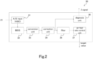
- FIG. 2 is a block diagram related to the processing of the air-fuel ratio measured value obtained by the air-fuel ratio sensor 21.
- the air-fuel ratio sensor 21 is made of a metal that varies in voltage depending on the oxygen concentration, such as zirconium oxide or the like. First, an analog signal indicating a voltage to be measured by the air-fuel ratio sensor 21 is inputted to an A/D input portion 31 of the controller 30.
- the A/D input portion 31 is configured by an ASIC (Application Specific Integrated Circuit), and digitally converts the inputted voltage signal and outputs the digitally converted voltage value.
- the voltage value outputted from the A/D input unit 31 is outputted to a conversion unit 33 via a BIOS (Basic Input Output System) 32 that controls inputs and outputs related to hardware processing in the controller 30.
- BIOS Basic Input Output System
- the conversion unit 33 obtains the oxygen concentration corresponding to the voltage obtained by the air-fuel ratio sensor 21 by using a table stored in advance that associates the detected voltage by the air-fuel ratio sensor 21 with the oxygen concentration, and calculates the air-fuel ratio on the basis of this oxygen concentration. Furthermore, the conversion unit 33 outputs the calculated air-fuel ratio to a correction unit 34.
- the correction unit 34 performs a predetermined correction corresponding to an exhaust gas state with respect to the air-fuel ratio obtained by the conversion unit 33, and obtains the air-fuel ratio measured value.
- the obtained air-fuel ratio measured value is outputted to a diagnosis unit 35, and a filter 36.
- the diagnosis unit 35 determines whether or not the air-fuel ratio measured value is within a normal range. When the air-fuel ratio measured value is not within the normal range, the diagnosis unit 35 determines that the engine 1 is not operating normally and there is the possibility of misfire or the like.
- the controller 30 may display a warning or the like to a driver in response to a diagnosis result of the diagnosis unit 35.
- the filter 36 removes noise that occur in the air-fuel ratio measured value, and the air-fuel ratio measured value that has undergone the filtering process is outputted to an air-fuel ratio control unit 37.
- trend processing Prior to or following the filter 36, trend processing may be performed.
- a predetermined trend value (average value) in a previous stage of the filter 36 is subtracted in advance, and a trend value is added in the subsequent stage of the filter 36.
- the air-fuel ratio control unit 37 obtains a target value of the air-fuel ratio in the combustion chamber 2 of the engine 1 by using the air-fuel ratio measured value from which noise is removed by the filter 36, and outputs the target value to a subordinate controller (not illustrated).
- the subordinate controller controls the air-fuel ratio in the combustion chamber 2 by controlling the fuel injection valve 14 to achieve the target value calculated by the air-fuel ratio control unit 37.
- the air-fuel ratio control unit 37 feedback control is carried out.
- a transfer function that models a plant is obtained by system identification of the plant subject to the control, and the feedback control is performed by using the transfer function.
- the transfer function indicates a delay in an output with respect to an input, and hence a current state of the plant can be estimated by the output of the plant by using the transfer function. Furthermore, the plant can be controlled on the basis of the estimated state.
- a sliding mode control is performed.
- the control subject is indicated by a state space representation, and a state variable of the control subject is restricted on a predetermined hyperplane in this state space, to control by sliding the state of the system towards an origin on the hyperplane.
- Such sliding mode control has high durability.
- calculation in the state space has increased in speed by calculators, and the system identification of the plant can be performed relatively easily.
- Parameters a 0 , a 1 , b 0 , and b 1 in Formula (1) are defined by the system identification in the plant. More specifically, the system identification in a case in which the sliding mode control is performed, a plurality of observed values of input and output in the plant is used to perform a matrix calculation using a computer, and as a result, the parameters in Formula (1) are obtained.
- the air-fuel ratio control unit 37 estimates the air-fuel ratio in the combustion chamber 2 from the air-fuel ratio measured value by using the transfer function, and on the basis of this estimated air-fuel ratio, the air-fuel ratio in the combustion chamber 2 can be controlled.
- the filter 36 utilizes the transfer function shown in Formula (1) and used in the feedback control in the air-fuel ratio control unit 37. This is because, since the transfer function represents the delay in detection of the air-fuel ratio in the plant, by using the transfer function as a filter, it is possible to cut out a component with faster response speed than the delay indicated by the transfer function, namely, a high frequency component impossible to obtain by the air-fuel ratio sensor 21.
- a sampling cycle of the filter 36 may be longer than the sampling cycles of the conversion unit 33 and the correction unit 34. This is because, the air-fuel ratio control unit 37 that uses the output from the filter 36 has a relatively low request for immediacy as compared to the diagnosis unit 35, and hence the sampling cycle may be made long, and also by making the sampling cycle long, more noise can be removed.
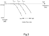
- FIG. 3 is a view illustrating filtering characteristics of the transfer function of Formula (1).
- x-axis indicates frequency
- y-axis indicates output strength.
- the illustrated three types of transfer functions are used in a switching manner, in response to the intake flow rate supplied to the engine 1.
- These three types of transfer functions are low pass filters that transmit signals of low frequency, and the higher the intake flow rate, the higher the cutoff frequency f cut . This is caused by the delay from the input of the air-fuel ratio in the combustion chamber 2 of the engine 1 to the output of the air-fuel ratio measured value obtained by the air-fuel ratio sensor 21 being smaller with a higher intake flow rate.
- the cutoff frequency f cut_a in the case of the maximum intake flow rate is the greatest, and as the intake flow rate decreases, the cutoff frequency decreases in the order of the cutoff frequency f cut_b , the cut-off frequency f cut_c .
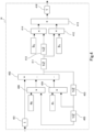
- FIG. 4 is a system configuration diagram of the filter 36. In this drawing, a discretized system is illustrated for the transfer function of Formula (1).
- a value inputted to block 401 is outputted from the block 416 in the end upon undergoing an internal process of the filter 36.
- a denominator part in the transfer function (1 / (1 + a 1 z -1 + a 0 z -2 )) is processed, and in the blocks 411 to 416 in the second half, a numerator part in the transfer function (b 1 z -1 + b 0 z -2 ) is processed.
- both are connected in series; once an input is received at block 401, a value having been undergone the filter processing is outputted from the block 416 in the end.
- a primary delay component is obtained by an output from the block 402 undergoing the delay block 403, and by multiplying a 1 to this primary delay component by the block 404, a primary delay feedback component is obtained. Furthermore, with respect to the output from the block 402, a secondary delay component is obtained by undergoing the delay blocks 403 and 405, and by multiplying ao by the block 406 with respect to this secondary delay component, a secondary delay feedback component is obtained. Furthermore, in the block 402, the primary delay feedback component obtained by the block 404 and the secondary delay feedback component obtained by the block 405 are subtracted from the input value from the air-fuel ratio sensor 21, to obtain the denominator part of the transfer function.
- the primary delay component is obtained by the output from the block 402 undergoing the delay block 411, and the primary delay feedback component is obtained by multiplying b 1 by the block 412 with respect to this primary delay component.
- the secondary delay component is obtained by the output from the block 402 undergoing the delay blocks 411 and 413, and the secondary delay feedback component is obtained by multiplying b 0 by the block 414 with respect to this secondary delay component.
- the primary delay feedback component obtained by the block 412 and the secondary delay feedback component obtained by the block 414 are added together, to find the numerator part of the transfer function.
- the system illustrated in this drawing connects in series the denominator part of Formula (1) by the blocks 401 to 406 of the first half, and the numerator part of Formula (1) by the blocks 411 to 416 of the second half.
- This system is one discretizing the transfer function of Formula (1), and is equivalent to the transfer function of Formula (1).
- FIGs. 5A, 5B are views illustrating timing charts of the present embodiment and a comparative example.
- FIG. 5A is a timing chart of the air-fuel ratio in a case in which the fuel is injected and the air-fuel ratio changes stepwise.
- FIG. 5B is a timing chart of the air-fuel ratio upon convergence to the target value in a case in which a control similar to FIG. 5A is performed.
- the air-fuel ratio measured value obtained by the air-fuel ratio sensor 21 is illustrated as the solid line
- the target value is illustrated as the dotted line.
- an output value from the filter 36 of Formula (1) of the present embodiment is illustrated as a long dashed short dashed line
- an output value in a case in which a weighted mean filter is used as the filter 36 is illustrated as a long dashed double short dashed line.
- the filter 36 of Formula (1) of the present embodiment has a similar degree of conformability with respect to the output value from the air-fuel ratio sensor 21 upon comparing with the case in which the weighted mean filter is used in the comparative example.
- the value obtained by using the filter 36 configured of Formula (1) of the present embodiment is held down in high frequency noise included in the output from the air-fuel ratio sensor 21.
- the value obtained by using the filter 36 of the present embodiment is smaller in difference with the output value from the air-fuel ratio sensor 21 overall, than the comparative example.
- the filter 36 of Formula (1) of the present embodiment has a performance of a similar degree as the weighted mean filter in the comparative example. Furthermore, the transfer function used in the air-fuel ratio control unit 37 is utilized for the filter 36, hence it is possible to hold down development manhour.
- a transfer function illustrated in Formula (1) that models the plant is used, and the transfer function illustrated in Formula (1) was utilized in the filter 36, however it is not to this.
- the transfer function illustrated in Formula (1) is used, and the feedback control of the air-fuel ratio control unit 37 may use a transfer function other than that of Formula (1).
- This transfer function represents a delay in detection of the air-fuel ratio in the plant; hence the output that has passed through the transfer function includes just the frequency acquirable by the air-fuel ratio sensor 21. Therefore, by using the transfer function in the filter 36 as the low pass filter, it is possible to cut the high frequency noise impossible to respond in the plant.
- the feedback control is performed in the air-fuel ratio control portion 37, and in this feedback control, a transfer function that can be achieved by system identifying the plant is used. Therefore, the transfer function used in the feedback control in the air-fuel ratio control portion 37 may be utilized in the filter 36. As a result, no additional steps are necessary to design the filter 36, and allows for reducing the entire number of developing steps.
- the greater the intake flow rate the greater the cutoff frequency of the transfer function being the low pass filter.
- the filter 36 obtained by the system identification in the plant in the case in which the intake flow rate is maximum, a signal of a higher frequency will transmit through the filter 36.
- the sliding mode control is used for the feedback control in the air-fuel ratio control unit 37.
- the sliding mode control is high in durability, and can perform system identification relatively easily by a calculator. Therefore, the system identification of the plant in the case in which the sliding mode control is rendered can be performed by the calculator; hence, reduction effect in the developing manhour increases.
- the filter 36 is one discretizing the transfer function used in the feedback control in the air-fuel ratio control unit 37.
- the sampling cycle of the input to the air-fuel ratio control unit 37 can be varied. Therefore, by varying the sampling cycle, it is possible to accomplish the engine system 100 including both stability and immediacy in feedback control.
Landscapes
- Engineering & Computer Science (AREA)
- Chemical & Material Sciences (AREA)
- Combustion & Propulsion (AREA)
- Mechanical Engineering (AREA)
- General Engineering & Computer Science (AREA)
- Electrical Control Of Air Or Fuel Supplied To Internal-Combustion Engine (AREA)
- Combined Controls Of Internal Combustion Engines (AREA)
Claims (3)
- Steuerverfahren eines Motorsystems (100), wobei das Motorsystem (100) Folgendes umfasst:einen Motor (1) mit einer Brennkammer (2);ein Kraftstoffeinspritzventil (14), das konfiguriert ist, um dem Motor (1) Kraftstoff zuzuführen; undeinen Luft-Kraftstoff-Verhältnis-Sensor (21), der in einem Strömungsweg (20) von Abgas von dem Motor (1) bereitgestellt ist,wobei das Steuerverfahren des Motorsystems (100) eine Rückkopplungssteuerung durchführt, sodass ein Luft-Kraftstoff-Verhältnis in der Brennkammer (2) ein Zielwert wird, indem das Kraftstoffeinspritzventil (14) unter Verwendung eines durch den Luft-Kraftstoff-Verhältnis-Sensor (21) erhaltenen Luft-Kraftstoff-Verhältnis-Messwerts gesteuert wird,wobei in der Rückkopplungssteuerung eine durch die folgende Formel (1) angegebene Übertragungsfunktion verwendet wird:

wobei ein Filterprozess unter Verwendung eines Tiefpassfilters, der durch Diskretisieren der in der Rückkopplungssteuerung verwendeten Übertragungsfunktion erhalten wird, auf einen in der Rückkopplungssteuerung verwendeten Luft-Kraftstoff-Verhältnis-Messwert basierend auf der Übertragungsfunktion durchgeführt wird. - Steuerverfahren eines Motorsystems (100) nach Anspruch 1, wobei
die Rückkopplungssteuerung auf der Basis einer Gleitmodussteuerung durchgeführt wird. - Motorsystem (100), das Folgendes umfasst:einen Motor (1) mit einer Brennkammer (2);ein Kraftstoffeinspritzventil (14), das konfiguriert ist, um dem Motor (1) Kraftstoff zuzuführen;einen Luft-Kraftstoff-Verhältnis-Sensor (21), der in einem Strömungsweg (20) von Abgas von dem Motor (1) bereitgestellt ist; undeine Steuerung (30), die konfiguriert ist, um eine Rückkopplungssteuerung durchzuführen, sodass ein Luft-Kraftstoff-Verhältnis in der Brennkammer (2) ein Zielwert wird, indem das Kraftstoffeinspritzventil (14) unter Verwendung eines durch den Luft-Kraftstoff-Verhältnis-Sensor (21) erhaltenen Luft-Kraftstoff-Verhältnis-Messwerts gesteuert wird,wobei in der Steuerung eine durch die folgende Formel (2) angegebene Übertragungsfunktion verwendet wird:

wobei ein Filterprozess unter Verwendung eines Tiefpassfilters, der durch Diskretisieren der in der Rückkopplungssteuerung verwendeten Übertragungsfunktion erhalten wird, auf einen in der Rückkopplungssteuerung verwendeten Luft-Kraftstoff-Verhältnis-Messwert basierend auf der Übertragungsfunktion durchgeführt wird.
Applications Claiming Priority (1)
| Application Number | Priority Date | Filing Date | Title |
|---|---|---|---|
| PCT/JP2019/018035 WO2020217484A1 (ja) | 2019-04-26 | 2019-04-26 | エンジンシステムの制御方法、及び、エンジンシステム |
Publications (3)
| Publication Number | Publication Date |
|---|---|
| EP3961020A1 EP3961020A1 (de) | 2022-03-02 |
| EP3961020A4 EP3961020A4 (de) | 2022-05-04 |
| EP3961020B1 true EP3961020B1 (de) | 2024-12-25 |
Family
ID=72940891
Family Applications (1)
| Application Number | Title | Priority Date | Filing Date |
|---|---|---|---|
| EP19925565.4A Active EP3961020B1 (de) | 2019-04-26 | 2019-04-26 | Motorsystemsteuerungsverfahren und motorsystem |
Country Status (5)
| Country | Link |
|---|---|
| US (1) | US11703007B2 (de) |
| EP (1) | EP3961020B1 (de) |
| JP (1) | JP7192972B2 (de) |
| CN (1) | CN113728160B (de) |
| WO (1) | WO2020217484A1 (de) |
Family Cites Families (18)
| Publication number | Priority date | Publication date | Assignee | Title |
|---|---|---|---|---|
| JPH05300371A (ja) * | 1992-04-17 | 1993-11-12 | Omron Corp | 画像処理用フィルタ回路 |
| JP2856986B2 (ja) | 1992-07-31 | 1999-02-10 | 三菱電機株式会社 | 内燃機関の空燃比制御装置 |
| US5781875A (en) * | 1995-02-25 | 1998-07-14 | Honda Giken Kogyo Kabushiki Kaisha | Fuel metering control system for internal combustion engine |
| JP3354088B2 (ja) * | 1997-09-16 | 2002-12-09 | 本田技研工業株式会社 | 内燃機関の排気系の空燃比制御装置 |
| JP2003314347A (ja) * | 2002-04-18 | 2003-11-06 | Denso Corp | 内燃機関の筒内充填空気量検出装置 |
| JP3957180B2 (ja) * | 2002-08-09 | 2007-08-15 | 本田技研工業株式会社 | デシメーションフィルタを用いた内燃機関の空燃比制御装置 |
| JP2004360591A (ja) * | 2003-06-05 | 2004-12-24 | Toyota Motor Corp | 内燃機関の排気浄化装置 |
| JP2005042788A (ja) * | 2003-07-25 | 2005-02-17 | Aisin Seiki Co Ltd | 自動変速機の変速制御装置 |
| JP2007162565A (ja) * | 2005-12-14 | 2007-06-28 | Toyota Motor Corp | 内燃機関の空燃比制御装置 |
| JP2006233973A (ja) * | 2006-03-13 | 2006-09-07 | Honda Motor Co Ltd | 制御装置 |
| JP4919945B2 (ja) * | 2007-12-12 | 2012-04-18 | 日立オートモティブシステムズ株式会社 | エンジンのスライディングモード制御による空燃比制御方法、及びその方法を備えた燃料制御装置 |
| JP4930722B2 (ja) * | 2007-12-25 | 2012-05-16 | トヨタ自動車株式会社 | 内燃機関の制御装置 |
| JP2010019106A (ja) * | 2008-07-08 | 2010-01-28 | Denso Corp | 制御装置 |
| US9757254B2 (en) * | 2014-08-15 | 2017-09-12 | Honda Motor Co., Ltd. | Integral admittance shaping for an exoskeleton control design framework |
| US9359967B2 (en) * | 2014-09-03 | 2016-06-07 | Ford Global Technologies, Llc | Method for identification of a threshold-level catalyst |
| US9657663B2 (en) * | 2015-09-24 | 2017-05-23 | Ford Global Technologies, Llc | Systems and methods for an air-fuel ratio imbalance monitor |
| JP6747087B2 (ja) * | 2016-06-21 | 2020-08-26 | いすゞ自動車株式会社 | 路面勾配推定装置及び路面勾配推定方法 |
| US11223303B2 (en) * | 2017-06-19 | 2022-01-11 | Nikon Research Corporation Of America | Motor with force constant modeling and identification for flexible mode control |
-
2019
- 2019-04-26 CN CN201980095743.2A patent/CN113728160B/zh active Active
- 2019-04-26 EP EP19925565.4A patent/EP3961020B1/de active Active
- 2019-04-26 WO PCT/JP2019/018035 patent/WO2020217484A1/ja not_active Ceased
- 2019-04-26 US US17/606,160 patent/US11703007B2/en active Active
- 2019-04-26 JP JP2021515714A patent/JP7192972B2/ja active Active
Also Published As
| Publication number | Publication date |
|---|---|
| WO2020217484A1 (ja) | 2020-10-29 |
| CN113728160B (zh) | 2023-03-31 |
| US20220243675A1 (en) | 2022-08-04 |
| CN113728160A (zh) | 2021-11-30 |
| EP3961020A4 (de) | 2022-05-04 |
| EP3961020A1 (de) | 2022-03-02 |
| US11703007B2 (en) | 2023-07-18 |
| JP7192972B2 (ja) | 2022-12-20 |
| JPWO2020217484A1 (de) | 2020-10-29 |
Similar Documents
| Publication | Publication Date | Title |
|---|---|---|
| JP4390104B2 (ja) | 内燃機関のノック判定装置 | |
| JP4756968B2 (ja) | 内燃機関のノック判定装置 | |
| EP1672346B1 (de) | Klopferkennungsgerät für Verbrennungsmotoren | |
| US6202406B1 (en) | Method and apparatus for catalyst temperature control | |
| US5533332A (en) | Method and apparatus for self diagnosis of an internal combustion engine | |
| US6688286B2 (en) | Knock control apparatus for engine | |
| EP1947313B1 (de) | Bestimmung der Anomalität eines Luftansaugsystems eines Verbrennungsmotors | |
| US20030131587A1 (en) | Engine exhaust gas leak diagnosis | |
| JP2001234804A (ja) | イオン電流による内燃機関のノック検出方法 | |
| CN114810392A (zh) | 一种发动机燃气需求量的确定方法和相关装置 | |
| JP2007170345A (ja) | 内燃機関の燃焼異常検出装置 | |
| JPH07119530A (ja) | 内燃機関の燃焼状態検出装置 | |
| EP3961020B1 (de) | Motorsystemsteuerungsverfahren und motorsystem | |
| US7661408B2 (en) | Method for operating internal combustion engine | |
| US6244042B1 (en) | Method for monitoring an internal combustion engine | |
| JP3412350B2 (ja) | 内燃機関のノック判定装置 | |
| JP4925251B2 (ja) | 内燃機関のノック判定装置 | |
| JPH0933478A (ja) | 内燃機関における酸素センサの応答診断装置 | |
| JP4241579B2 (ja) | 内燃機関の燃焼状態検出装置 | |
| JP3972925B2 (ja) | 内燃機関の触媒劣化検出装置 | |
| JPH08303234A (ja) | 内燃機関の触媒劣化診断装置 | |
| JP2006161587A (ja) | 車両の故障判定装置 | |
| JP2017180120A (ja) | 内燃機関の制御装置 | |
| JPH09119309A (ja) | 内燃機関の触媒劣化検出装置 | |
| JP2017031865A (ja) | 内燃機関の失火判定装置 |
Legal Events
| Date | Code | Title | Description |
|---|---|---|---|
| STAA | Information on the status of an ep patent application or granted ep patent |
Free format text: STATUS: THE INTERNATIONAL PUBLICATION HAS BEEN MADE |
|
| PUAI | Public reference made under article 153(3) epc to a published international application that has entered the european phase |
Free format text: ORIGINAL CODE: 0009012 |
|
| STAA | Information on the status of an ep patent application or granted ep patent |
Free format text: STATUS: REQUEST FOR EXAMINATION WAS MADE |
|
| 17P | Request for examination filed |
Effective date: 20211026 |
|
| AK | Designated contracting states |
Kind code of ref document: A1 Designated state(s): AL AT BE BG CH CY CZ DE DK EE ES FI FR GB GR HR HU IE IS IT LI LT LU LV MC MK MT NL NO PL PT RO RS SE SI SK SM TR |
|
| A4 | Supplementary search report drawn up and despatched |
Effective date: 20220404 |
|
| RIC1 | Information provided on ipc code assigned before grant |
Ipc: F02D 41/14 20060101ALI20220329BHEP Ipc: F02D 45/00 20060101AFI20220329BHEP |
|
| DAV | Request for validation of the european patent (deleted) | ||
| DAX | Request for extension of the european patent (deleted) | ||
| GRAP | Despatch of communication of intention to grant a patent |
Free format text: ORIGINAL CODE: EPIDOSNIGR1 |
|
| STAA | Information on the status of an ep patent application or granted ep patent |
Free format text: STATUS: GRANT OF PATENT IS INTENDED |
|
| GRAS | Grant fee paid |
Free format text: ORIGINAL CODE: EPIDOSNIGR3 |
|
| GRAA | (expected) grant |
Free format text: ORIGINAL CODE: 0009210 |
|
| STAA | Information on the status of an ep patent application or granted ep patent |
Free format text: STATUS: THE PATENT HAS BEEN GRANTED |
|
| INTG | Intention to grant announced |
Effective date: 20241105 |
|
| AK | Designated contracting states |
Kind code of ref document: B1 Designated state(s): AL AT BE BG CH CY CZ DE DK EE ES FI FR GB GR HR HU IE IS IT LI LT LU LV MC MK MT NL NO PL PT RO RS SE SI SK SM TR |
|
| REG | Reference to a national code |
Ref country code: GB Ref legal event code: FG4D |
|
| REG | Reference to a national code |
Ref country code: CH Ref legal event code: EP |
|
| REG | Reference to a national code |
Ref country code: DE Ref legal event code: R096 Ref document number: 602019064105 Country of ref document: DE |
|
| REG | Reference to a national code |
Ref country code: IE Ref legal event code: FG4D |
|
| REG | Reference to a national code |
Ref country code: LT Ref legal event code: MG9D |
|
| PG25 | Lapsed in a contracting state [announced via postgrant information from national office to epo] |
Ref country code: HR Free format text: LAPSE BECAUSE OF FAILURE TO SUBMIT A TRANSLATION OF THE DESCRIPTION OR TO PAY THE FEE WITHIN THE PRESCRIBED TIME-LIMIT Effective date: 20241225 |
|
| PG25 | Lapsed in a contracting state [announced via postgrant information from national office to epo] |
Ref country code: FI Free format text: LAPSE BECAUSE OF FAILURE TO SUBMIT A TRANSLATION OF THE DESCRIPTION OR TO PAY THE FEE WITHIN THE PRESCRIBED TIME-LIMIT Effective date: 20241225 |
|
| PG25 | Lapsed in a contracting state [announced via postgrant information from national office to epo] |
Ref country code: BG Free format text: LAPSE BECAUSE OF FAILURE TO SUBMIT A TRANSLATION OF THE DESCRIPTION OR TO PAY THE FEE WITHIN THE PRESCRIBED TIME-LIMIT Effective date: 20241225 |
|
| PG25 | Lapsed in a contracting state [announced via postgrant information from national office to epo] |
Ref country code: NO Free format text: LAPSE BECAUSE OF FAILURE TO SUBMIT A TRANSLATION OF THE DESCRIPTION OR TO PAY THE FEE WITHIN THE PRESCRIBED TIME-LIMIT Effective date: 20250325 |
|
| PG25 | Lapsed in a contracting state [announced via postgrant information from national office to epo] |
Ref country code: LV Free format text: LAPSE BECAUSE OF FAILURE TO SUBMIT A TRANSLATION OF THE DESCRIPTION OR TO PAY THE FEE WITHIN THE PRESCRIBED TIME-LIMIT Effective date: 20241225 Ref country code: GR Free format text: LAPSE BECAUSE OF FAILURE TO SUBMIT A TRANSLATION OF THE DESCRIPTION OR TO PAY THE FEE WITHIN THE PRESCRIBED TIME-LIMIT Effective date: 20250326 |
|
| PG25 | Lapsed in a contracting state [announced via postgrant information from national office to epo] |
Ref country code: RS Free format text: LAPSE BECAUSE OF FAILURE TO SUBMIT A TRANSLATION OF THE DESCRIPTION OR TO PAY THE FEE WITHIN THE PRESCRIBED TIME-LIMIT Effective date: 20250325 |
|
| REG | Reference to a national code |
Ref country code: NL Ref legal event code: MP Effective date: 20241225 |
|
| PG25 | Lapsed in a contracting state [announced via postgrant information from national office to epo] |
Ref country code: NL Free format text: LAPSE BECAUSE OF FAILURE TO SUBMIT A TRANSLATION OF THE DESCRIPTION OR TO PAY THE FEE WITHIN THE PRESCRIBED TIME-LIMIT Effective date: 20241225 |
|
| REG | Reference to a national code |
Ref country code: AT Ref legal event code: MK05 Ref document number: 1754338 Country of ref document: AT Kind code of ref document: T Effective date: 20241225 |
|
| PG25 | Lapsed in a contracting state [announced via postgrant information from national office to epo] |
Ref country code: SM Free format text: LAPSE BECAUSE OF FAILURE TO SUBMIT A TRANSLATION OF THE DESCRIPTION OR TO PAY THE FEE WITHIN THE PRESCRIBED TIME-LIMIT Effective date: 20241225 |
|
| PG25 | Lapsed in a contracting state [announced via postgrant information from national office to epo] |
Ref country code: PL Free format text: LAPSE BECAUSE OF FAILURE TO SUBMIT A TRANSLATION OF THE DESCRIPTION OR TO PAY THE FEE WITHIN THE PRESCRIBED TIME-LIMIT Effective date: 20241225 |
|
| PGFP | Annual fee paid to national office [announced via postgrant information from national office to epo] |
Ref country code: DE Payment date: 20250428 Year of fee payment: 7 |
|
| PG25 | Lapsed in a contracting state [announced via postgrant information from national office to epo] |
Ref country code: ES Free format text: LAPSE BECAUSE OF FAILURE TO SUBMIT A TRANSLATION OF THE DESCRIPTION OR TO PAY THE FEE WITHIN THE PRESCRIBED TIME-LIMIT Effective date: 20241225 |
|
| PGFP | Annual fee paid to national office [announced via postgrant information from national office to epo] |
Ref country code: GB Payment date: 20250423 Year of fee payment: 7 |
|
| PG25 | Lapsed in a contracting state [announced via postgrant information from national office to epo] |
Ref country code: IS Free format text: LAPSE BECAUSE OF FAILURE TO SUBMIT A TRANSLATION OF THE DESCRIPTION OR TO PAY THE FEE WITHIN THE PRESCRIBED TIME-LIMIT Effective date: 20250425 |
|
| PG25 | Lapsed in a contracting state [announced via postgrant information from national office to epo] |
Ref country code: PT Free format text: LAPSE BECAUSE OF FAILURE TO SUBMIT A TRANSLATION OF THE DESCRIPTION OR TO PAY THE FEE WITHIN THE PRESCRIBED TIME-LIMIT Effective date: 20250428 |
|
| PG25 | Lapsed in a contracting state [announced via postgrant information from national office to epo] |
Ref country code: EE Free format text: LAPSE BECAUSE OF FAILURE TO SUBMIT A TRANSLATION OF THE DESCRIPTION OR TO PAY THE FEE WITHIN THE PRESCRIBED TIME-LIMIT Effective date: 20241225 |
|
| PGFP | Annual fee paid to national office [announced via postgrant information from national office to epo] |
Ref country code: FR Payment date: 20250422 Year of fee payment: 7 |
|
| PG25 | Lapsed in a contracting state [announced via postgrant information from national office to epo] |
Ref country code: RO Free format text: LAPSE BECAUSE OF FAILURE TO SUBMIT A TRANSLATION OF THE DESCRIPTION OR TO PAY THE FEE WITHIN THE PRESCRIBED TIME-LIMIT Effective date: 20241225 Ref country code: AT Free format text: LAPSE BECAUSE OF FAILURE TO SUBMIT A TRANSLATION OF THE DESCRIPTION OR TO PAY THE FEE WITHIN THE PRESCRIBED TIME-LIMIT Effective date: 20241225 |
|
| PG25 | Lapsed in a contracting state [announced via postgrant information from national office to epo] |
Ref country code: SK Free format text: LAPSE BECAUSE OF FAILURE TO SUBMIT A TRANSLATION OF THE DESCRIPTION OR TO PAY THE FEE WITHIN THE PRESCRIBED TIME-LIMIT Effective date: 20241225 |
|
| PG25 | Lapsed in a contracting state [announced via postgrant information from national office to epo] |
Ref country code: CZ Free format text: LAPSE BECAUSE OF FAILURE TO SUBMIT A TRANSLATION OF THE DESCRIPTION OR TO PAY THE FEE WITHIN THE PRESCRIBED TIME-LIMIT Effective date: 20241225 |
|
| PG25 | Lapsed in a contracting state [announced via postgrant information from national office to epo] |
Ref country code: IT Free format text: LAPSE BECAUSE OF FAILURE TO SUBMIT A TRANSLATION OF THE DESCRIPTION OR TO PAY THE FEE WITHIN THE PRESCRIBED TIME-LIMIT Effective date: 20241225 |
|
| PG25 | Lapsed in a contracting state [announced via postgrant information from national office to epo] |
Ref country code: SE Free format text: LAPSE BECAUSE OF FAILURE TO SUBMIT A TRANSLATION OF THE DESCRIPTION OR TO PAY THE FEE WITHIN THE PRESCRIBED TIME-LIMIT Effective date: 20241225 |
|
| REG | Reference to a national code |
Ref country code: DE Ref legal event code: R097 Ref document number: 602019064105 Country of ref document: DE |
|
| PG25 | Lapsed in a contracting state [announced via postgrant information from national office to epo] |
Ref country code: DK Free format text: LAPSE BECAUSE OF FAILURE TO SUBMIT A TRANSLATION OF THE DESCRIPTION OR TO PAY THE FEE WITHIN THE PRESCRIBED TIME-LIMIT Effective date: 20241225 |
|
| PLBE | No opposition filed within time limit |
Free format text: ORIGINAL CODE: 0009261 |
|
| STAA | Information on the status of an ep patent application or granted ep patent |
Free format text: STATUS: NO OPPOSITION FILED WITHIN TIME LIMIT |
|
| REG | Reference to a national code |
Ref country code: CH Ref legal event code: L10 Free format text: ST27 STATUS EVENT CODE: U-0-0-L10-L00 (AS PROVIDED BY THE NATIONAL OFFICE) Effective date: 20251105 |
|
| REG | Reference to a national code |
Ref country code: CH Ref legal event code: H13 Free format text: ST27 STATUS EVENT CODE: U-0-0-H10-H13 (AS PROVIDED BY THE NATIONAL OFFICE) Effective date: 20251125 |
|
| 26N | No opposition filed |
Effective date: 20250926 |
|
| PG25 | Lapsed in a contracting state [announced via postgrant information from national office to epo] |
Ref country code: LU Free format text: LAPSE BECAUSE OF NON-PAYMENT OF DUE FEES Effective date: 20250426 |
|
| PG25 | Lapsed in a contracting state [announced via postgrant information from national office to epo] |
Ref country code: MC Free format text: LAPSE BECAUSE OF FAILURE TO SUBMIT A TRANSLATION OF THE DESCRIPTION OR TO PAY THE FEE WITHIN THE PRESCRIBED TIME-LIMIT Effective date: 20241225 |
|
| REG | Reference to a national code |
Ref country code: BE Ref legal event code: MM Effective date: 20250430 |
|
| PG25 | Lapsed in a contracting state [announced via postgrant information from national office to epo] |
Ref country code: BE Free format text: LAPSE BECAUSE OF NON-PAYMENT OF DUE FEES Effective date: 20250430 |
|
| PG25 | Lapsed in a contracting state [announced via postgrant information from national office to epo] |
Ref country code: CH Free format text: LAPSE BECAUSE OF NON-PAYMENT OF DUE FEES Effective date: 20250430 |