EP3958765B1 - Set zur dorsalen wirbelfusion sowie handgriff für ein medizinisches werkzeug - Google Patents
Set zur dorsalen wirbelfusion sowie handgriff für ein medizinisches werkzeug Download PDFInfo
- Publication number
- EP3958765B1 EP3958765B1 EP20732491.4A EP20732491A EP3958765B1 EP 3958765 B1 EP3958765 B1 EP 3958765B1 EP 20732491 A EP20732491 A EP 20732491A EP 3958765 B1 EP3958765 B1 EP 3958765B1
- Authority
- EP
- European Patent Office
- Prior art keywords
- handle
- spinal fusion
- needle
- dorsal spinal
- fusion
- Prior art date
- Legal status (The legal status is an assumption and is not a legal conclusion. Google has not performed a legal analysis and makes no representation as to the accuracy of the status listed.)
- Active
Links
Images


Classifications
-
- A—HUMAN NECESSITIES
- A61—MEDICAL OR VETERINARY SCIENCE; HYGIENE
- A61B—DIAGNOSIS; SURGERY; IDENTIFICATION
- A61B17/00—Surgical instruments, devices or methods
- A61B17/56—Surgical instruments or methods for treatment of bones or joints; Devices specially adapted therefor
- A61B17/58—Surgical instruments or methods for treatment of bones or joints; Devices specially adapted therefor for osteosynthesis, e.g. bone plates, screws or setting implements
- A61B17/68—Internal fixation devices, including fasteners and spinal fixators, even if a part thereof projects from the skin
- A61B17/70—Spinal positioners or stabilisers, e.g. stabilisers comprising fluid filler in an implant
- A61B17/7074—Tools specially adapted for spinal fixation operations other than for bone removal or filler handling
- A61B17/7076—Tools specially adapted for spinal fixation operations other than for bone removal or filler handling for driving, positioning or assembling spinal clamps or bone anchors specially adapted for spinal fixation
- A61B17/7082—Tools specially adapted for spinal fixation operations other than for bone removal or filler handling for driving, positioning or assembling spinal clamps or bone anchors specially adapted for spinal fixation for driving, i.e. rotating, screws or screw parts specially adapted for spinal fixation, e.g. for driving polyaxial or tulip-headed screws
-
- A—HUMAN NECESSITIES
- A61—MEDICAL OR VETERINARY SCIENCE; HYGIENE
- A61B—DIAGNOSIS; SURGERY; IDENTIFICATION
- A61B17/00—Surgical instruments, devices or methods
- A61B17/56—Surgical instruments or methods for treatment of bones or joints; Devices specially adapted therefor
- A61B17/58—Surgical instruments or methods for treatment of bones or joints; Devices specially adapted therefor for osteosynthesis, e.g. bone plates, screws or setting implements
- A61B17/68—Internal fixation devices, including fasteners and spinal fixators, even if a part thereof projects from the skin
- A61B17/70—Spinal positioners or stabilisers, e.g. stabilisers comprising fluid filler in an implant
- A61B17/7074—Tools specially adapted for spinal fixation operations other than for bone removal or filler handling
- A61B17/7091—Tools specially adapted for spinal fixation operations other than for bone removal or filler handling for applying, tightening or removing longitudinal element-to-bone anchor locking elements, e.g. caps, set screws, nuts or wedges
-
- A—HUMAN NECESSITIES
- A61—MEDICAL OR VETERINARY SCIENCE; HYGIENE
- A61B—DIAGNOSIS; SURGERY; IDENTIFICATION
- A61B17/00—Surgical instruments, devices or methods
- A61B17/56—Surgical instruments or methods for treatment of bones or joints; Devices specially adapted therefor
- A61B17/58—Surgical instruments or methods for treatment of bones or joints; Devices specially adapted therefor for osteosynthesis, e.g. bone plates, screws or setting implements
- A61B17/88—Osteosynthesis instruments; Methods or means for implanting or extracting internal or external fixation devices
- A61B17/8863—Apparatus for shaping or cutting osteosynthesis equipment by medical personnel
-
- A—HUMAN NECESSITIES
- A61—MEDICAL OR VETERINARY SCIENCE; HYGIENE
- A61B—DIAGNOSIS; SURGERY; IDENTIFICATION
- A61B50/00—Containers, covers, furniture or holders specially adapted for surgical or diagnostic appliances or instruments, e.g. sterile covers
- A61B50/20—Holders specially adapted for surgical or diagnostic appliances or instruments
-
- A—HUMAN NECESSITIES
- A61—MEDICAL OR VETERINARY SCIENCE; HYGIENE
- A61B—DIAGNOSIS; SURGERY; IDENTIFICATION
- A61B50/00—Containers, covers, furniture or holders specially adapted for surgical or diagnostic appliances or instruments, e.g. sterile covers
- A61B50/30—Containers specially adapted for packaging, protecting, dispensing, collecting or disposing of surgical or diagnostic appliances or instruments
- A61B50/33—Trays
-
- B—PERFORMING OPERATIONS; TRANSPORTING
- B25—HAND TOOLS; PORTABLE POWER-DRIVEN TOOLS; MANIPULATORS
- B25B—TOOLS OR BENCH DEVICES NOT OTHERWISE PROVIDED FOR, FOR FASTENING, CONNECTING, DISENGAGING OR HOLDING
- B25B23/00—Details of, or accessories for, spanners, wrenches, screwdrivers
- B25B23/0007—Connections or joints between tool parts
- B25B23/0042—Connection means between screwdriver handle and screwdriver shaft
-
- A—HUMAN NECESSITIES
- A61—MEDICAL OR VETERINARY SCIENCE; HYGIENE
- A61B—DIAGNOSIS; SURGERY; IDENTIFICATION
- A61B17/00—Surgical instruments, devices or methods
- A61B17/56—Surgical instruments or methods for treatment of bones or joints; Devices specially adapted therefor
- A61B17/58—Surgical instruments or methods for treatment of bones or joints; Devices specially adapted therefor for osteosynthesis, e.g. bone plates, screws or setting implements
- A61B17/68—Internal fixation devices, including fasteners and spinal fixators, even if a part thereof projects from the skin
- A61B17/70—Spinal positioners or stabilisers, e.g. stabilisers comprising fluid filler in an implant
- A61B17/7001—Screws or hooks combined with longitudinal elements which do not contact vertebrae
- A61B17/7032—Screws or hooks with U-shaped head or back through which longitudinal rods pass
-
- A—HUMAN NECESSITIES
- A61—MEDICAL OR VETERINARY SCIENCE; HYGIENE
- A61B—DIAGNOSIS; SURGERY; IDENTIFICATION
- A61B17/00—Surgical instruments, devices or methods
- A61B2017/00367—Details of actuation of instruments, e.g. relations between pushing buttons, or the like, and activation of the tool, working tip, or the like
- A61B2017/00407—Ratchet means
-
- A—HUMAN NECESSITIES
- A61—MEDICAL OR VETERINARY SCIENCE; HYGIENE
- A61B—DIAGNOSIS; SURGERY; IDENTIFICATION
- A61B17/00—Surgical instruments, devices or methods
- A61B2017/0042—Surgical instruments, devices or methods with special provisions for gripping
- A61B2017/00424—Surgical instruments, devices or methods with special provisions for gripping ergonomic, e.g. fitting in fist
-
- A—HUMAN NECESSITIES
- A61—MEDICAL OR VETERINARY SCIENCE; HYGIENE
- A61B—DIAGNOSIS; SURGERY; IDENTIFICATION
- A61B17/00—Surgical instruments, devices or methods
- A61B2017/0046—Surgical instruments, devices or methods with a releasable handle; with handle and operating part separable
-
- A—HUMAN NECESSITIES
- A61—MEDICAL OR VETERINARY SCIENCE; HYGIENE
- A61B—DIAGNOSIS; SURGERY; IDENTIFICATION
- A61B17/00—Surgical instruments, devices or methods
- A61B2017/0046—Surgical instruments, devices or methods with a releasable handle; with handle and operating part separable
- A61B2017/00464—Surgical instruments, devices or methods with a releasable handle; with handle and operating part separable for use with different instruments
-
- A—HUMAN NECESSITIES
- A61—MEDICAL OR VETERINARY SCIENCE; HYGIENE
- A61B—DIAGNOSIS; SURGERY; IDENTIFICATION
- A61B50/00—Containers, covers, furniture or holders specially adapted for surgical or diagnostic appliances or instruments, e.g. sterile covers
- A61B2050/005—Containers, covers, furniture or holders specially adapted for surgical or diagnostic appliances or instruments, e.g. sterile covers with a lid or cover
- A61B2050/0065—Peelable cover
-
- A—HUMAN NECESSITIES
- A61—MEDICAL OR VETERINARY SCIENCE; HYGIENE
- A61B—DIAGNOSIS; SURGERY; IDENTIFICATION
- A61B50/00—Containers, covers, furniture or holders specially adapted for surgical or diagnostic appliances or instruments, e.g. sterile covers
- A61B50/30—Containers specially adapted for packaging, protecting, dispensing, collecting or disposing of surgical or diagnostic appliances or instruments
- A61B2050/3008—Containers specially adapted for packaging, protecting, dispensing, collecting or disposing of surgical or diagnostic appliances or instruments having multiple compartments
-
- A—HUMAN NECESSITIES
- A61—MEDICAL OR VETERINARY SCIENCE; HYGIENE
- A61B—DIAGNOSIS; SURGERY; IDENTIFICATION
- A61B50/00—Containers, covers, furniture or holders specially adapted for surgical or diagnostic appliances or instruments, e.g. sterile covers
- A61B50/30—Containers specially adapted for packaging, protecting, dispensing, collecting or disposing of surgical or diagnostic appliances or instruments
- A61B2050/3015—Containers specially adapted for packaging, protecting, dispensing, collecting or disposing of surgical or diagnostic appliances or instruments transparent
-
- A—HUMAN NECESSITIES
- A61—MEDICAL OR VETERINARY SCIENCE; HYGIENE
- A61B—DIAGNOSIS; SURGERY; IDENTIFICATION
- A61B90/00—Instruments, implements or accessories specially adapted for surgery or diagnosis and not covered by any of the groups A61B1/00 - A61B50/00, e.g. for luxation treatment or for protecting wound edges
- A61B90/03—Automatic limiting or abutting means, e.g. for safety
- A61B2090/037—Automatic limiting or abutting means, e.g. for safety with a frangible part, e.g. by reduced diameter
Definitions
- the invention relates to a set for dorsal vertebral fusion, as well as a handle designed therefor, which is designed to accommodate a drive of a screwdriver.
- screws with a tulip head with a passage for a fusion rod are used in practice.
- the screws are inserted into the vertebral body as bone screws, and then a rod is pushed through the opening in the tulips of the screw heads. After the rod is secured with a lock, the vertebral bodies are locked together using the rods.
- an access needle is first inserted through the skin to mark the canal.
- a guide wire is then inserted, the soft tissue is widened using a dilator and the screws are inserted, which are then connected to the rods.
- the rods can each be secured with a fastener.
- This can be a fastener with a nut and a breakaway headpiece, which breaks off when a predetermined torque is reached.
- Removable handles can be used as a drive, especially for the screwdrivers used.
- a square drive on screwdrivers has proven particularly popular, as it can be locked onto a handle without the need for tools.
- Such a ratchet handle is known, for example, from the document WO 2013/178932 A1 known.
- Ratchet handles are from the documents US 2019/022833 A1 and WO 2013/178932 A1 known.
- the invention in contrast, has the object of providing a set for dorsal vertebral fusion and a handle which can be used therefor, which can be produced easily and inexpensively and, in particular, enables the provision of a disposable instrumentation.
- the object of the invention is already achieved by a set for dorsal vertebral fusion and by a handle for a medical tool according to claim 1.
- the invention relates to a set for dorsal spinal fusion, which is particularly designed as a disposable instrument set.
- the tools included in the set can be arranged in sterile packaging, for example, in a tear-open blister pack.
- the set comprises at least one removable handle made of plastic and at least one screwdriver that can be coupled to the removable handle without tools, wherein a holder for the handle for the screwdriver is made of plastic.
- the invention makes it possible to form the receptacle for the tool drive in one piece with the handle.
- a suitable handle can be manufactured cost-effectively in this way.
- a plastic receptacle is sufficient for use of the handle in a disposable instrument set.
- the receptacle for the screwdriver drive is made of plastic. This can, for example, be polygonal or, in particular, square.
- the handle is preferably made of a polymer, in particular, a thermoplastic. This allows for production by injection molding.
- Polyacrylamide has proven to be particularly suitable.
- a fiber-reinforced plastic in particular a glass-fiber-reinforced polyacrylamide, can be used for the handle.
- the handle comprises a tool holder made of plastic, wherein the drive of a tool can be locked by means of a resilient hook made of plastic, which is an integral part of the handle.
- a spring-loaded L-shaped hook is used, which is formed as a single piece with the main body of the handle or a component of the handle.
- the spring-loaded hook is an integral part of a main body of the handle or an integral part of the sleeve of a ratchet mechanism.
- the handle is preferably designed as an elongated handle.
- a tool holder is provided on both a long side and a narrow side.
- the handle can be used to form a T-shaped arrangement with the tool or, coupled at its narrow side, can be aligned axially to the tool according to its main extension direction.
- the T-shaped arrangement enables the application of the highest possible torque, whereas the axial alignment enables faster screwing in or out as well as more precise angular guidance in many applications.
- the handle is designed as a ratchet handle.
- a ratchet handle comprises a plastic gear which is inserted into the main housing and into which a pawl engages, which blocks the rotation of the plastic gear in one direction of rotation.
- the ratchet mechanism is designed to be non-reversible.
- the tool can be engaged in the holder from two different sides.
- the gear is an integral part of the tool holder.
- the gear is part of a sleeve which comprises at least one, preferably two resilient hooks with which the tool, in particular the screwdriver, can be locked.
- the set may further comprise at least one guide sleeve that can be placed on a bone screw, a dilator, a counterholder for a guide sleeve, a holder for a fusion rod and/or a flank breaker for the tulip via a fusion screw.
- the holder for the fusion rod can preferably be coupled to the handle. This allows for a particularly compact holder.
- the flank breaker for the tulip of the fusion screw comprises the counterholder for the guide sleeve.
- the flank breaker can comprise one end with a drive, for example a hexagon, and another end with a channel into which the flank can be inserted and then broken off.
- This provides a tool with dual functionality, which reduces the number of tools required and enables the set to be provided more cost-effectively.
- the invention further relates to the flank breaker described above, regardless of whether it is part of the set described above.
- the invention relates to a handle for a medical tool, which is designed for the set described above.
- the handle i.e. at least the main housing of the handle, is made of plastic and the handle comprises a ratchet mechanism with a plastic gear into which a pawl engages, which blocks rotation in one direction of rotation.
- the gear wheel is in turn part of a tool holder into which the drive of a tool, in particular a screwdriver, can be locked.
- the gear is in particular part of a sleeve which encloses the tool holder.
- the sleeve also comprises at least one resilient hook for locking the tool.
- the resilient hook is, in particular, an integral component of the sleeve.
- the hook can be provided together with the sleeve as a one-piece injection-molded component.
- the set for dorsal vertebral fusion also comprises a needle, in particular an access needle.
- An access needle comprises a hollow needle which is separable from an inner needle.
- a trocar is an instrument used in minimally invasive surgery to create access to a body cavity, either sharply or bluntly, and to keep it open using a hollow needle, the so-called tube.
- the inner needle is a pin that sits inside the tube, and its tip closes the opening.
- the needle in particular the hollow needle, comprises a groove for engagement of the resilient hook.
- the set includes an additional handle for the needle.
- This handle may have a different ergonomic design than the handle described above.
- the handle is used to position the access needle.
- the handle comprises a coupling for an extension, in particular an angled extension.
- the extension allows the access needle to be positioned under X-ray control without the user having to reach into the beam path.
- the counterholder/flank breaker described above can be used as an extension.
- the coupling can in particular be designed as a hexagon on the proximal side of the handle.
- the locking is effected by a hook which is an integral part of the handle, in particular a main housing of the handle.
- the main housing of the handle or a component of the handle can be formed as a one-piece injection-molded component together with the resilient hook.
- the handle is particularly designed in such a way that it can be connected to the tool in two positions rotated by 90°.
- the handle can also be used as a mere extension of a tool, in particular the dorsal spine fusion set, and not as a drive for rotation.
- the receptacle comprises a ratchet mechanism on the long side.
- the handle is designed for coupling to a needle, in particular an access needle.
- the handle can include a passage for the needle.
- a needle coupled to the handle includes a groove in which the spring-loaded hook of the handle engages.
- a hollow needle encompasses the groove.
- the hollow needle can then be snapped onto the handle and detached from it.
- An inner needle can be withdrawn preferably proximally from the handle and the hollow needle coupled to the handle.
- the inner needle may comprise a holder which in turn can be coupled to the handle, in particular via a thread in the passage for the needle.
- the handle comprises on a proximal side a coupling for an extension, in particular an angled extension such as the counterholder described above.
- the needle handle is preferably designed to be gripped from the side relative to the needle.
- the handle can have a cylindrical or bulbous shape.
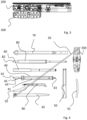
- Fig. 1 is a top view of a set 1 for dorsal spinal fusion, which includes at least some of the instruments used for this purpose.
- the set is designed as a blister pack 11, which comprises a tear-off, transparent film 12.
- the blister pack comprises a molded tray 13 which contains recesses for the individual instruments.
- Fig. 3 is a side view of the narrow side of the set.
- two handles namely a handle with a ratchet mechanism 200 and another handle 300 without a ratchet mechanism, are arranged one above the other.
- one of the two handles 200 or 300 can be used.
- Fig. 4 shows a top view of the instruments included in the set.
- the set includes a guide wire 20, which is inserted via an access needle, in addition to the handle 200.
- the access needle is not part of the set in this embodiment, as most surgeons have a particular preference for a specific access needle.
- the set also includes a dilator 30, which can be pushed onto the guide wire 20 and with which the soft tissue can be dilated.
- the set For inserting the fusion screws, the set includes the screwdriver 40.
- the screwdriver 40 comprises a sleeve 41 with a handle 44, in which the drive 42 is rotatably mounted for attachment to the handle 200, which is coupled to the screw drive 43.
- the drive 42 is in particular polygonal, e.g. square-shaped, in order to be driven in a form-fitting manner by the correspondingly shaped receptacle of the handle.
- the screwdriver 40 To use the screwdriver 40, it is inserted into the handle 200 with the drive 42.
- the screwdriver 40 can be inserted and removed without tools.
- the set also includes guide sleeves 50, which can be coupled to the fusion screws and, in particular, can be used to align the fusion screws.
- the position of the fusion screws can be adjusted using a distraction handle 60 that can be inserted into the tulip of the screw.
- the screwdriver 80 is used to insert a lock that connects the fusion rod to the screw.
- the screwdriver 80 can also be coupled to the handle 200 via a drive 82.
- the set also includes a combined counterholder/flank breaker 70, with which the guide sleeves 50 can be held in position and with which the flanks of the tulip of the fusion screw can be broken off at the end of the operation.
- the rod 91 included in the set can be connected to the rod holder 90, but is only used to test whether the fusion screws are correctly aligned.
- the fusion rods are then inserted via the rod holder 90.
- the rod holder 90 also includes a drive 92 and can thus be coupled to the handle 200.
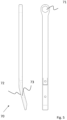
- Fig. 5 is a view of the combined counterholder/flank breaker 70.
- This comprises a key 71 on one side, which is designed in particular as a hexagon. This can be used as a counter-holder for the Fig. 3
- the guide sleeves 50 shown can be used.
- the combined counterholder/flank breaker 70 comprises an angled head piece 72 which comprises a channel 73.
- the tool With channel 73, the tool can also be pushed onto the flank of the fusion screw and the flank can then be broken off.
- the combined counterholder/flank breaker is preferably made of plastic, in particular as a one-piece plastic injection-molded component.
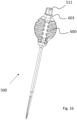
- Fig. 6 and Fig. 7 are perspective views of a screw 400 which can be processed with the instruments of the set according to the invention.
- the screw 400 comprises a tulip 410 with flanks 411.
- the flanks 411 can be segmented. For example, sections of the flanks 411 can be broken off to adjust the height of the flanks 411.
- the tulip 410 comprises a thread 412 into which the Fig. 4 shown distraction handles (reference numeral 60) can be inserted.
- the drive 440 of the screw 400 is arranged in the tulip 410, via which the thread 420 can be screwed into the bone.
- the drive 440 can be designed, for example, as a hexagon or as a hexalobular socket.
- the tulip 410 comprises through holes 430 through which the rods can be pushed for fusion.
- flanks 411 are then treated with the Fig. 5
- the flank breaker shown was broken off.
- Fig. 8 is a perspective view of a handle 200 incorporating a ratchet mechanism.
- the handle 200 is elongated and in this embodiment comprises a profile 210 which makes it easier to grasp.
- the handle 200 includes a centrally arranged receptacle 220 for a tool, in particular a screwdriver.
- the tool can be inserted into the receptacle 220 from either side.
- the handle 200 comprises on its narrow side a further receptacle 230 which serves for the insertion of a tool.
- a spring-loaded hook 240 can be seen, with which the tool, which has a corresponding groove, is locked.
- the tool can be inserted and removed without any tools.
- Fig. 9 is a sectional view of the Fig. 8 handle shown.
- the tool holder 230 can be seen with a polygonal, in particular square, section 231 for driving the tool. Adjacent to the polygonal section 231, the resilient hook 240 protrudes into the tool holder 230.
- the polygonal section 431 is made of the same plastic as the rest of the handle. This eliminates the need for a complex metal insert.
- the resilient hook 240 comprises an engagement element 241, which in this embodiment is rounded at its end and which engages in a groove of the inserted tool.
- the spring-loaded hook 240 bends to the side. In the inserted state, the spring-loaded hook 240 engages a groove of the tool (45 in Fig. 4 ).
- the engagement element 241 can spring in when the tool is inserted or removed.
- the spring-loaded hook 240 is integral with the handle 200 and is made of plastic.
- the user can either arrange the handle 200 axially according to its main extension direction to the tool using the receptacle 230 or, using the receptacle 220, couple the tool to the handle in a T-shaped arrangement.
- the handle 200 includes a ratchet mechanism comprising a sleeve 221 with the receptacle 220.
- Fig. 10 is a perspective view of this sleeve 221.
- the sleeve 221 is made of plastic and includes a gear 222 as an integral part.
- the gear 222 is arranged centrally in the sleeve 221.
- the spring-loaded hook 240 is designed according to the Fig. 9 shown springy hook.
- the resilient hook 240 can in particular be L-shaped.
- the spring-loaded hooks 240 which are an integral part of the plastic sleeve 221, enable a tool to be inserted from both sides and locked into place via the spring-loaded hooks 240.
- the sleeve 221 comprises a polygonal section 243, which serves to drive the tool.
- the polygonal section 243 lies within the gear 222.
- Fig. 12 is a perspective view of the sleeve 221 and a pawl 223, which is pressed against the gear 222 of the sleeve by means of a spring 224 (also called insert).
- the pawl 223 is attached to the main housing.
- the pawl 223 engages with the gear 222 and thus causes the sleeve 221 to be rotated over the main housing in only one direction.
- the pawl 223 can deflect against the spring tension 224 and the sleeve 221 can be rotated.
- Fig. 13 shows the components of the handle with the ratchet mechanism in an exploded view.
- the handle consists of a main housing 201, which has a recess 225 for receiving the ratchet mechanism.
- the sleeve 221 is inserted into the recess 225 and is rotatably mounted there.
- the pawl 223 with the spring 226 is inserted when assembling the handle.
- the sleeve 221 together with the pawl 223 and spring 226 is then secured axially by inserting the insert 224 into the recess 225.
- the insert 224 can be secured, for example, by locking or by means of a material bond, e.g., by gluing or welding.
- the components of the ratchet mechanism are thus easily secured in the recess 225 of the main housing 201.
- all components of the handle are made of a plastic material.
- these components are injection-molded.
- Fig. 14 is a perspective detailed view of recess 225.
- the main housing includes a recess 228 for the pawl and spring within the recess 225.
- An axis 227 for the pawl is formed as an integral pin-shaped component of the main housing.
- the pawl is inserted into the recess 228 together with the spring.
- the sleeve (221) is then placed into the recess 225 and the assembly is completed by inserting the insert 224.
- Fig. 14 shows a side view of a handle 300 which does not include a ratchet mechanism.
- This handle can also be coupled to the tool in a T-shape or axially aligned manner.
- the handle 300 comprises the receptacle 220 into which the tool, for example the screwdriver, can be inserted.
- a spring-loaded hook 240 which is an integral part of the main housing 201 of the handle, enables the handle to be locked in place without the use of tools.
- the handle 300 corresponding to the previously illustrated handle with the reference numeral 200, comprises on its narrow side a receptacle 230 for a tool.
- At least one of the spring hooks can be open at the side, as shown here.
- this enables a visual check to determine whether the spring-loaded hook 240 engages in the groove of the tool.
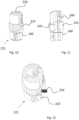
- Fig. 16 is a view of one embodiment of an access needle 500 with a handle 600.
- the handle 600 is designed to be gripped from the side.
- the handle 600 comprises a coupling 603 for a holder (see, for example, Fig. 5 ).
- the handle 600 can also be guided outside the beam path under X-ray control.
- the coupling 603 can be designed, for example, as a polygon, e.g., a hexagon.
- An inner needle 510 can be withdrawn via a proximal holder 511.
- Fig. 17 is a sectional view of the access needle 500. This includes a hollow needle 520 with an inner needle 510.
- the handle 600 includes a passage 601 for the needles 510, 520.
- the resilient hook 240 is an integral component of the plastic handle 600 and can be configured, in particular, according to the exemplary embodiments described above.
- the hook 240 is openly accessible from one side.
- the holder 511 of the inner needle 510 extends through the passage 601.
- the holder 511 is connected to the handle 600 via a thread 602 in the passage 601.
- the holder 511 can be unscrewed together with the inner needle 510 and the inner needle 510 can thus be removed.
- the outer needle 520 can be pulled out distally by releasing the locking mechanism.
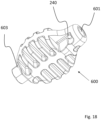
- Fig. 18 is a perspective view of only the handle 600.
- the handle 600 is formed as a monolithic body made of a fiber-reinforced plastic, including the hook 240 and the coupling 603.
- the invention made it possible to provide a disposable instrumentation for dorsal vertebral fusion, which is inexpensive to manufacture and allows for good handling and flexibility.
Landscapes
- Health & Medical Sciences (AREA)
- Orthopedic Medicine & Surgery (AREA)
- Surgery (AREA)
- Life Sciences & Earth Sciences (AREA)
- Neurology (AREA)
- Engineering & Computer Science (AREA)
- Heart & Thoracic Surgery (AREA)
- Biomedical Technology (AREA)
- Nuclear Medicine, Radiotherapy & Molecular Imaging (AREA)
- Medical Informatics (AREA)
- Molecular Biology (AREA)
- Animal Behavior & Ethology (AREA)
- General Health & Medical Sciences (AREA)
- Public Health (AREA)
- Veterinary Medicine (AREA)
- Mechanical Engineering (AREA)
- Surgical Instruments (AREA)
- Prostheses (AREA)
Description
- Die Erfindung betrifft ein Set zur dorsalen Wirbelfusion, sowie einen dafür ausgebildeten Handgriff, welcher zur Aufnahme eines Antriebs eines Schraubendrehers ausgebildet ist.
- Für die dorsale Wirbelfusion werden in der Praxis insbesondere Schrauben verwendet, deren Kopf eine Tulpe mit einer Durchführung für eine Fusionsstange aufweist.
- Die Schrauben werden als Knochenschrauben in den Wirbelkörper eingebracht und sodann wird eine Stange durch die Öffnung in den Tulpen der Schraubenköpfe geschoben. Nach Befestigen der Stange mittels eines Verschlusses sind die Wirbelkörper über die Stangen verblockt.
- Hierfür wird in der Praxis zumeist ein umfangreiches Instrumentarium verwendet. In der Regel wird zunächst mit einer Zugangsnadel durch die Haut punktiert und so der Kanal markiert.
- Sodann wird ein Führungsdraht eingesetzt, mittels eines Dilators das Weichgewebe aufgeweitet und die Schrauben eingebracht, welche sodann mit den Stäben verbunden werden.
- Zum Abschluss können die Stäbe mit jeweils einem Verschluss fixiert werden. Es kann sich dabei insbesondere um einen Verschluss mit einer Mutter mit einem abbrechbaren Kopfstück handeln, welches beim Erreichen eines bauartbedingt vorgegebenen Drehmoments abbricht. Als Antrieb, insbesondere für die verwendeten Schraubendreher, können abnehmbare Griffe verwendet werden. Insbesondere hat sich in der Praxis ein Vierkantantrieb an den Schraubendrehern etabliert, welcher werkzeuglos an einem Handgriff verrastet werden kann.
- Da das Einbringen der Schrauben mühsam ist, bevorzugen manche Anwender Ratschengriffe.
- Ein derartiger Ratschengriff ist beispielsweise aus dem Dokument
WO 2013/178932 A1 bekannt. - Die aus der Praxis bekannten Sets, welche zumindest einen Teil der für die dorsalen Wirbelfusion benötigten Instrumente umfassen, sind zumeist vollständig als Mehrweginstrumentarium ausgebildet. Dies hat zwangsläufig eine kostspielige und aufwändige Sterilisation des Instrumentariums nach jeder Verwendung zur Folge.
- Bei aus der Praxis bekannten Instrumentarien, insbesondere mit vorstehend genanntem Ratschengriff, ist allerdings zumeist die Aufnahme für den Antrieb des Werkzeugs derartig aufwändig ausgebildet, dass die Griffe recht kostspielig herzustellen sind.
- Eine Verwendung eines derartigen Griffes, bei dem insbesondere die Hülse zur Aufnahme des Antriebs aus Metall ausgebildet ist, als Teil eines Einweginstrumentariums macht daher keinen Sinn.
- Zur medizinischen Verwendung bestimmte Werkzeuge mit einem Handgriff sind aus den Dokumenten
US 2017/224399 A1 ,US 2015/174754 A1 ,US 2006/241627 A1 ,US 2017/189082 A1 undUS 2016/346017 A1 bekannt. - Ratschengriffe sind aus den Dokumenten
US 2019/022833 A1 undWO 2013/178932 A1 bekannt. - Der Erfindung obliegt demgegenüber die Aufgabe, ein Set zur dorsalen Wirbelfusion sowie einen dafür verwendbaren Handgriff bereit zu stellen, welches bzw. welcher einfach und kostengünstig herzustellen ist und insbesondere die Bereitstellung eines Einweginstrumentariums ermöglicht.
- Die Aufgabe der Erfindung wird bereits durch ein Set zur dorsalen Wirbelfusion sowie durch einen Handgriff für ein medizinisches Werkzeug nach Anspruch 1 gelöst.
- Bevorzugte Ausführungsformen und Weiterbildungen der Erfindung sind Gegenstand der abhängigen Ansprüche.
- Die Erfindung betrifft ein Set zur dorsalen Wirbelfusion, welches insbesondere als Einweginstrumentarium ausgebildet ist. Die in dem Set vorhandenen Werkzeuge können insbesondere in einer sterilen Verpackung, beispielsweise in einer aufreißbaren Blisterverpackung, angeordnet sein.
- Das Set umfasst zumindest einen abnehmbaren Handgriff aus Kunststoff sowie zumindest einen mit dem abnehmbaren Handgriff werkzeuglos koppelbaren Schraubendreher, wobei eine Aufnahme des Handgriffes für den Schraubendreher aus Kunststoff besteht.
- Im Unterschied zu bekannten Handgriffen mit einer Aufnahme, die in der Regel eine mit Kunststoff umspritzte Metallhülse umfasst, ist es durch die Erfindung möglich, die Aufnahme für den Werkzeugantrieb einstückig mit dem Griff auszubilden.
- Es hat sich herausgestellt, dass so kostengünstig ein geeigneter Griff herstellbar ist. Insbesondere bei Wahl eines geeigneten Kunststoffes reicht eine aus Kunststoff ausgebildete Aufnahme für die Verwendung des Griffes im Rahmen eines Einweginstrumentariums aus. Es besteht also insbesondere die Aufnahme für den Antrieb des Schraubendrehers aus Kunststoff. Diese kann z.B. polygonförmig, insbesondere vierkantförmig, ausgebildet sein. Der Handgriff besteht vorzugsweise aus einem Polymer, insbesondere aus einem Thermoplast. Dies ermöglicht eine Herstellung im Spritzgussverfahren.
- Als besonders geeignet hat sich insbesondere eine Polyacrylamid erwiesen.
- Insbesondere kann für den Handgriff ein faserverstärkter Kunststoff, insbesondere ein glasfaserverstärktes Polyacrylamid, verwendet werden.
- Gemäß der Erfindung umfasst der Handgriff eine Werkzeugaufnahme aus Kunststoff, wobei der Antrieb eines Werkzeugs mittels eines federnden Hakens aus Kunststoff, welcher integraler Bestandteil des Handgriffes ist, verrastbar ist.
- Zum Einrasten des Werkzeugs wird ein federnder L-förmig ausgebildeter Haken verwendet, welcher zusammen mit dem Hauptgehäuse des Handgriffes oder einem Bestandteil des Handgriffes einstückig ausgebildet ist.
- Der Haken federt allein durch die elastischen Eigenschaften des Kunststoffmaterials. Auf eine separate Feder kann so verzichtet werden.
- Der federnde Haken ist integraler Bestandteil eines Hauptgehäuses des Griffes oder integraler Bestandteil der Hülse eines Ratschenmechanismus.
- Der Handgriff ist vorzugsweise als länglicher Griff ausgebildet.
- Gemäß einer Ausführungsform der Erfindung ist sowohl an einer Langseite als auch an einer Schmalseite eine Werkzeugaufnahme vorhanden.
- Der Griff kann so, je nach Einsatzzweck und Präferenz, verwendet werden, um mit dem Werkzeug eine T-förmige Anordnung zu bilden oder, angekoppelt an seiner Schmalseite, entsprechend seiner Haupterstreckungsrichtung axial zum Werkzeug ausgerichtet sein.
- Die T-förmige Anordnung ermöglicht das Aufbringen eines möglichst hohen Drehmoments, wohingegen die axiale Ausrichtung bei vielen Anwendungen ein schnelleres Ein- oder Herausdrehen sowie eine exaktere Winkelführung ermöglicht.
- Gemäß der Erfindung ist der Handgriff als Ratschengriff ausgebildet.
- Die Erfindung sieht insbesondere vor, dass ein derartiger Ratschengriff ein Kunststoffzahnrad umfasst, welches in das Hauptgehäuse eingesetzt ist und in welches eine Sperrklinke greift, die die Drehung des Kunststoffzahnrads in eine Drehrichtung blockiert.
- So kann ein einfach ausgestalteter Ratschenmechanismus bereitgestellt werden, welcher aus nur wenigen Teilen besteht.
- Erfindungsgemäß ist der Ratschenmechanismus nicht umschaltbar ausgebildet. Zum Ändern der Drehrichtung kann das Werkzeug von zwei verschiedenen Seiten in die Aufnahme eingerastet werden.
- Das Zahnrad ist insbesondere integraler Bestandteil der Werkzeugaufnahme.
- Insbesondere ist das Zahnrad Teil einer Hülse, welche zumindest einen, vorzugsweise zwei federnde Haken umfasst, mit dem bzw. denen das Werkzeug, insbesondere der Schraubendreher, verrastet werden kann.
- Das Set kann des Weiteren zumindest eine auf eine Knochenschraube aufsetzbare Führungshülse, einen Dilator, einen Gegenhalter für eine Führungshülse, einen Halter für einen Fusionsstab und/oder einen Flankenbrecher für die Tulpe über eine Fusionsschraube umfassen.
- Der Halter für den Fusionsstab ist vorzugsweise mit dem Handgriff koppelbar. So kann ein besonders kompakt ausgebildeter Halter bereitgestellt werden.
- Gemäß einer Ausführungsform der Erfindung umfasst der Flankenbrecher für die Tulpe der Fusionsschraube den Gegenhalter für die Führungshülse.
- Insbesondere kann der Flankenbrecher ein Ende mit einem Antrieb, beispielsweise einem Sechskant und ein anderes Ende mit einem Kanal umfassen, in welchen die Flanke eingeführt und sodann abgebrochen werden kann.
- So wird ein Werkzeug mit einer Doppelfunktionalität bereitgestellt, was die Anzahl der benötigten Werkzeuge reduziert und eine preiswertere Bereitstellung des Sets ermöglicht.
- Die Erfindung betrifft des Weiteren auch vorstehend beschriebenen Flankenbrecher, unabhängig davon, ob er Teil des vorstehend beschriebenen Sets ist.
- Weiter betrifft die Erfindung einen Handgriff für ein medizinisches Werkzeug, welcher für vorstehend beschriebenes Set ausgebildet ist.
- Gemäß der Erfindung besteht der Handgriff, also zumindest das Hauptgehäuse des Handgriffes, aus Kunststoff und der Handgriff umfasst einen Ratschenmechanismus mit einem Kunststoffzahnrad, in welches eine Sperrklinke greift, die eine Drehung in eine Drehrichtung blockiert.
- Das Zahnrad ist seinerseits Teil einer Werkzeugaufnahme, in welche der Antrieb eines Werkzeugs, insbesondere eines Schraubendrehers, verrastbar ist.
- Das Zahnrad ist insbesondere Teil einer Hülse, welche die Werkzeugaufnahme umfasst.
- Vorzugsweise umfasst die Hülse, wie vorstehend beschrieben, auch zumindest einen federnden Haken zum Verrasten des Werkzeugs.
- Der federnde Haken ist insbesondere integraler Bestandteil der Hülse. Insbesondere kann der Haken zusammen mit der Hülse als einstückiges Spritzgussbauteil bereitgestellt sein.
- Bei einer Weiterbildung der Erfindung umfasst das Set zur dorsalen Wirbelfusion auch eine Nadel, insbesondere eine Zugangsnadel.
- Eine Zugangsnadel umfasst eine Hohlnadel, welche von einer Innennadel trennbar ist.
- Ein derartiges medizinisches Instrument wird auch das Trokar bezeichnet. Der Trokar ist ein Instrument, mit dessen Hilfe in der minimalinvasiven Chirurgie scharf oder stumpf ein Zugang zu einer Körperhöhle geschaffen und durch die Hohlnadel, den sog. Tubus offengehalten wird. Die Innennadel ist ein Stift, der in dem Tubus sitzt, und deren Spitze die Öffnung des Tubus verschließt.
- Die Innennadel wird nach dem Einbringen des Trokar herausgezogen, ist also vom Trokar trennbar.
- Die Nadel, insbesondere die Hohlnadel, umfasst eine Nut zum Eingriff des federnden Hakens.
- Insbesondere umfasst das Set einen weiteren Griff für die Nadel.
- Dieser Griff kann eine andere ergonomische Ausgestaltung als vorstehend beschriebener Griff haben.
- Der Griff dient der Positionierung der Zugangsnadel.
- Bei einer Weiterbildung der Erfindung umfasst der Griff eine Kupplung für eine Verlängerung, insbesondere eine abgewinkelte Verlängerung.
- Durch die Verlängerung kann die Zugangsnadel unter Röntgenkontrolle positioniert werden, ohne dass der Benutzer in den Strahlengang greift.
- Als Verlängerung kann insbesondere vorstehend beschriebener Gegenhalter/Flankenbrecher verwendet werden.
- Die Kupplung kann insbesondere als Sechskant auf der proximalen Seite des Griffes ausgebildet sein.
- Die Verrastung wird durch einen Haken bewirkt, welcher integraler Bestandteil des Handgriffes, insbesondere eines Hauptgehäuses des Handgriffes, ist.
- Wie vorstehend beschrieben, kann insbesondere das Hauptgehäuse des Handgriffes oder ein Bauteil des Handgriffes, wie beispielsweise die vorstehend beschriebene Hülse des Ratschenmechanismuses als einstückiges Spritzgussbauteil zusammen mit dem federnden Haken ausgebildet sein.
- Der Handgriff ist insbesondere derart ausgebildet, dass dieser in zwei um 90° verdrehten Positionen mit dem Werkezeug verbunden sein kann.
- In axialer Ausrichtung zu dem Werkzeug kann der Handgriff auch als bloße Verlängerung eines Werkezeugs, insbesondere des Sets zur dorsalen Wirbelfusion, und nicht als Antrieb zum Drehen verwendet werden.
- Gemäß einer Ausführungsform der Erfindung umfasst die Aufnahme an der Langseite einen Ratschenmechanismus.
- Gemäß einer weiteren Ausführungsform der Erfindung ist der Handgriff zur Kopplung mit einer Nadel, insbesondere einer Zugangsnadel, ausgebildet.
- Hierzu kann der Griff eine Durchführung für die Nadel umfassen.
- Eine mit dem Griff gekoppelte Nadel umfasst eine Nut, in welcher der federnde Haken des Griffes verrastet.
- Insbesondere umfasst eine Hohlnadel die Nut. Die Hohlnadel kann so auf den Griff aufgerastet und vom Griff abgetrennt werden.
- Eine Innennadel kann vorzugsweise proximal aus dem Griff und der mit dem Griff gekoppelten Hohlnadel gezogen werden.
- Die Innennadel kann einen Halter umfassen, der seinerseits mit dem Griff koppelbar ist, insbesondere über ein Gewinde in der Durchführung für die Nadel.
- Bei einer Weiterbildung der Erfindung umfasst der Handgriff auf einer proximalen Seite eine Kupplung für eine Verlängerung, insbesondere eine abgewinkelte Verlängerung wie beispielsweise vorstehend beschriebenen Gegenhalter.
- Der Griff für die Nadel ist von seiner Form her vorzugsweise derart ausgebildet, um, bezogen auf die Nadel, von der Seite gegriffen zu werden. Hierzu kann der Griff eine zylindrische oder bauchige Formhaben.
- Die Erfindung soll im Folgenden Bezug nehmend auf ein in den Zeichnungen
Fig. 1 bis Fig. 18 dargestelltes Ausführungsbeispiel näher erläutert werden. -
Fig. 1 zeigt in der Draufsicht ein Set zur dorsalen Wirbelfusion. -
Fig. 2 zeigt das Set in einer Seitenansicht auf die Langseite undFig. 3 zeigt das Set in einer Seitenansicht auf die Schmalseite. -
Fig. 4 zeigt die in dem Set beispielhaft vorhandenen Instrumente. -
Fig. 5 ist eine Darstellung des in dem Set enthaltenen Flankenbrechers. -
Fig. 6 und Fig. 7 sind perspektivische Darstellungen einer Schraube, welche mit den Instrumenten des Sets eingebracht werden kann. -
Fig. 8 ist eine perspektivische Darstellung eines erfindungsgemäßen Ratschengriffes. -
Fig. 9 ist eine Schnittansicht des Ratschengriffes. -
Fig. 10 ist eine perspektivische Darstellung der Hülse mit einem Zahnrad, welche Bestandteil des Ratschenmechanismus ist. -
Fig. 11 ist eine perspektivische Schnittansicht der Hülse -
Fig. 12 zeigt in einer perspektivischen Darstellung die Hülse zusammen mit der Sperrklinke. -
Fig. 13 ist eine perspektivische Explosionsdarstellung der Bestandteile des Handgriffs. -
Fig. 14 ist eine perspektivische Detaildarstellung, in welche die Ausnehmung, in welcher der Ratschenmechanismus angeordnet ist, zu erkennen ist. -
Fig. 15 ist eine Ansicht eines weiteren Griffes, welcher keinen Ratschenmechanismus aufweist. -
Fig. 16 ist eine Ansicht eines Ausführungsbeispiels eines Griffes mit einer Zugangsnadel. -
Fig. 17 ist eine Schnittansicht des Griffes mit Nadel gemäßFig. 16 . -
Fig. 18 zeigt den Griff in einer Detailansicht. -
Fig. 1 ist eine Draufsicht auf ein Set 1 zur dorsalen Wirbelfusion, welches zumindest ein Teil der dafür verwendeten Instrumente umfasst. - Das Set ist als Blisterverpackung 11 ausgebildet, welche eine abreißbare, transparente Folie 12 umfasst.
- Wie in der Seitenansicht gemäß
Fig. 2 zu erkennen, umfasst die Blisterverpackung eine Formschale 13, die für die einzelnen Instrumente Mulden umfasst. - So kann eine übersichtliche Anordnung mit definierter Position der Einzelinstrumente auf einfache Weise bereitgestellt werden.
-
Fig. 3 ist eine Seitenansicht auf die Schmalseite des Sets. - Zu erkennen ist, dass in einer der Mulden der Formschale zwei Griffe, nämlich ein Griff mit einem Ratschenmechanismus 200 und ein weiterer Griff 300 ohne einen Ratschenmechanismus übereinander angeordnet sind.
- Je nachdem, welches Instrument gerade angekoppelt ist und je nach Präferenz des Anwenders, kann einer der beiden Griffe 200 oder 300 verwendet werden.
-
Fig. 4 zeigt in der Draufsicht die in dem Set vorhandenen Instrumente. - Das Set umfasst in diesem Ausführungsbeispiel neben dem Griff 200 einen Führungsdraht 20, welcher über eine Zugangsnadel eingesetzt wird. Die Zugangsnadel ist in diesem Ausführungsbeispiel nicht Teil des Sets, da die meisten Chirurgen eine besondere Präferenz für eine bestimmte Zugangsnadel haben.
- Weiter umfasst das Set einen Dilator 30, welcher auf den Führungsdraht 20 aufgeschoben werden kann und mit welchem das Weichgewebe aufgeweitet werden kann.
- Zum Einbringen der Fusionsschrauben umfasst das Set den Schraubendreher 40. Der Schraubendreher 40 umfasst eine Hülse 41 mit einem Griff 44, in welchem der Antrieb 42 zum Befestigen an dem Griff 200, der mit dem Schraubentrieb 43 gekoppelt ist, drehbar gelagert ist.
- Der Antrieb 42 ist insbesondere polygonförmig, z.B. vierkantförmig ausgebildet, um so formschlüssig durch die entsprechend geformte Aufnahme des Griffes angetrieben zu werden.
- Angrenzend zum Antrieb 42 ist eine Nut 45 angeordnet, in welcher ein Rastmittel, bei diesem Set ein federnder Haken des Griffes 200 einrastet und so den Schraubendreher axial sichert.
- Zum Verwenden des Schraubendrehers 40 wird dieser mit dem Antrieb 42 in den Griff 200 eingesetzt.
- Der Schraubendreher 40 kann werkzeuglos eingesetzt und wieder abgenommen werden.
- Weiter umfasst das Set Führungshülsen 50, welche mit den Fusionsschrauben gekoppelt werden können und über die insbesondere die Fusionsschrauben ausgerichtet werden können. Über einen in die Tulpe der Schraube einbringbaren Distraktionsgriff 60 kann die Position der Fusionsschrauben verändert werden.
- Der Schraubendreher 80 dient dem Einbringen eines Verschlusses, mit welcher der Fusionsstab mit der Schraube verbunden wird. Auch der Schraubendreher 80 ist mittels eines Antriebs 82 mit dem Griff 200 koppelbar.
- Weiter umfasst das Set einen kombinierten Gegenhalter/Flankenbrecher 70, mit welchem zum einen die Führungshülsen 50 in Position gehalten werden können und mit welchen zum anderen am Ende der Operation die Flanken der Tulpe der Fusionsschraube abgebrochen werden können.
- Die in dem Set enthaltene Stange 91 kann mit dem Stangenhalter 90 verbunden werden, dient aber nur dem Test, ob die Fusionsschrauben richtig ausgerichtet sind.
- Über den Stangenhalter 90 werden sodann die Fusionsstangen eingebracht.
- Der Stangenhalter 90 umfasst ebenfalls einen Antrieb 92 und kann so mit dem Griff 200 gekoppelt werden.
-
Fig. 5 ist eine Ansicht des kombinierten Gegenhalters/Flankenbrechers 70. - Dieser umfasst an einer Seite einen Schlüssel 71, welcher insbesondere als Sechskant ausgebildet ist. Dieser kann als Gegenhalter für die in
Fig. 3 dargestellten Führungshülsen 50 verwendet werden. - Auf der gegenüberliegenden Seite umfasst der kombinierte Gegenhalter/Flankenbrecher 70 ein abgewinkeltes Kopfstück 72, welches einen Kanal 73 umfasst.
- Mit dem Kanal 73 kann das Werkzeug auch auf die Flanke der Fusionsschraube geschoben werden und im Anschluss kann die Flanke abgebrochen werden.
- Der kombinierte Gegenhalter/Flankenbrecher ist vorzugsweise als Kunststoff, insbesondere als einstückiges Kunststoffspritzgussbauteil ausgebildet.
-
Fig. 6 und Fig. 7 sind perspektivische Ansichten einer Schraube 400, welche mit den Instrumenten des erfindungsgemäßen Sets verarbeitet werden kann. - Die Schraube 400 umfasst eine Tulpe 410 mit Flanken 411.
- Die Flanken 411 können segmentiert ausgebildet sein. So können beispielsweise Teilstücke der Flanken 411 abgebrochen werden, um die Höhe der Flanken 411 anzupassen.
- Weiter umfasst die Tulpe 410 ein Gewinde 412, in welches die in
Fig. 4 dargestellten Distraktionsgriffe (Bezugszeichen 60) eingebracht werden können. - In der Tulpe 410 angeordnet ist der Antrieb 440 der Schraube 400, über die das Gewinde 420 in den Knochen eingedreht werden kann.
- Der Antrieb 440 kann beispielsweise als Sechskant oder als Innensechsrund ausgebildet sein.
- Zum Einbringen der Schraube 400 in den Knochen wird der in
Fig. 4 dargestellte Schraubendreher mit dem Bezugszeichen 40 verwendet. - Wie in der Ansicht gem.
Fig. 7 zu erkennen, umfasst die Tulpe 410 Durchgangslöcher 430, durch die die Stangen zur Fusion geschoben werden können. - Über einen hier nicht dargestellten Verschluss, welcher in die Tulpe 410 mittels des in
Fig. 4 dargestellten Schraubendrehers mit dem Bezugszeichen 80 eingedreht werden kann, wird die Stange zur Fusion der Wirbelkörper befestigt. - Im Anschluss werden die Flanken 411 mit dem in
Fig. 5 dargestellten Flankenbrecher abgebrochen. -
Fig. 8 ist eine perspektivische Ansicht eines Griffes 200, welcher einen Ratschenmechanismus umfasst. - Der Griff 200 ist länglich ausgebildet und umfasst in diesem Ausführungsbeispiel eine Profilierung 210, mit der er sich leichter fassen lässt.
- Der Griff 200 umfasst eine mittig angeordnete Aufnahme 220 für ein Werkzeug, insbesondere für einen Schraubendreher. Das Werkzeug kann von beiden Seiten in die Aufnahme 220 eingesetzt werden.
- Weiter umfasst der Griff 200 an seiner Schmalseite eine weitere Aufnahme 230, welche dem Einsatz eines Werkzeugs dient.
- Zu erkennen ist in dieser Ansicht ein federnder Haken 240, mit welchem das Werkzeug, welches eine entsprechende Nut aufweist, verrastet wird.
- Das Werkzeug kann so werkzeuglos eingesetzt und entnommen werden.
-
Fig. 9 ist eine Schnittansicht des inFig. 8 dargestellten Griffes. - Zu erkennen ist die Werkzeugaufnahme 230 mit einem polygonförmigen, insbesondere vierkantförmigen, Abschnitt 231 zum Antrieb des Werkzeugs. Angrenzend zum polygonförmigen Abschnitt 231 ragt der federnde Haken 240 in die Werkzeugaufnahme 230 hinein.
- Der polygonförmige Abschnitt 431 besteht aus dem Kunststoff des restlichen Griffes. So kann auf einen aufwendig ausgestalteten Einsatz aus Metall verzichtet werden.
- Der federnde Haken 240 umfasst ein Eingriffelement 241, welches in diesem Ausführungsbeispiel an seinem Ende abgerundet ausgebildet ist und welches in eine Nut des eingesetzten Werkzeugs eingreift.
- Bei Einsetzen und Entnehmen des Werkzeugs biegt sich der federnde Haken 240 zur Seite. Im eingesetzten Zustand greift der federnde Haken 240 eine Nut des Werkzeugs (45 in
Fig. 4 ). - Über einen abgewinkelten federnden Träger 242, welcher einstückig mit dem Hauptgehäuse 201 des Griffes ausgebildet ist, kann das Eingriffelement 241 einfedern, wenn das Werkzeug eingesetzt oder entnommen wird.
- Der federnde Haken 240 ist einstückig mit dem Griff 200 und aus Kunststoff ausgebildet.
- Je nach Präferenz kann der Anwender entweder den Griff 200 unter Verwendung der Aufnahme 230 axial entsprechend seiner Haupterstreckungsrichtung zum Werkzeug anordnen oder, unter Verwendung der Aufnahme 220 das Werkzeug mit dem Griff in einer T-förmigen Anordnung koppeln.
- Der Griff 200 umfasst einen Ratschenmechanismus, der eine Hülse 221 mit der Aufnahme 220 umfasst.
-
Fig. 10 ist eine perspektivische Ansicht dieser Hülse 221. - Die Hülse 221 ist aus Kunststoff ausgebildet und umfasst als integralen Bestandteil ein Zahnrad 222.
- Das Zahnrad 222 ist mittig in der Hülse 221 angeordnet.
- Oberhalb und unterhalb des Zahnrades 222 erstrecken sich zwei Bereiche, in denen jeweils, wie in der perspektivischen Schnittansicht gemäß
Fig. 11 zu erkennen ist, ein federnder Haken 240 befindet. - Der federnde Haken 240 ist entsprechend des in
Fig. 9 dargestellten federnden Hakens ausgebildet. - Der federnde Haken 240 kann insbesondere L-förmig ausgebildet sein.
- Die federnden Haken 240, welche integraler Bestandteil der aus Kunststoff bestehenden Hülse 221 sind, ermöglichen, dass ein Werkzeug von beiden Seiten eingesetzt und über die federnden Haken 240 verrastet werden kann.
- Mittig umfasst die Hülse 221 einen polygonförmigen Abschnitt 243, welcher dem Antrieb des Werkezeugs dient.
- Der polygonförmige Abschnitt 243 liegt innerhalb des Zahnrads 222.
-
Fig. 12 ist eine perspektivische Ansicht der Hülse 221 sowie einer Sperrklinke 223, welche mittels einer Feder 224 (herein auch Einsatz genannt) gegen das Zahnrad 222 der Hülse gedrückt wird. - Die Sperrklinke 223 ist am Hauptgehäuse angeschlagen.
- Die Sperrklinke 223 greift in das Zahnrad 222 und bewirkt so, dass die Hülse 221 über dem Hauptgehäuse nur in eine Richtung verdreht werden kann.
- In einer Drehrichtung, in dieser Ansicht entgegen des Uhrzeigersinns, kann die Sperrklinke 223 gegen die Federspannung 224 ausweichen und die Hülse 221 kann gedreht werden.
- In der anderen Richtung laufen die Zähen des Zahnrads 222 gegen die Sperrklinke 223, so dass eine Verdrehsicherung gebildet ist.
- Um die gewünschte Drehrichtung zu ändern, kann das Werkzeug von beiden Seiten in die Hülse 221 eingesetzt werden
Fig. 13 zeigt in einer Explosionsdarstellung die Bestandteile des Griffes mit dem Ratschenmechanismus. - Der Griff besteht aus einem Hauptgehäuse 201, welches eine Ausnehmung 225 zur Aufnahme des Ratschenmechanismus aufweist.
- In die Ausnehmung 225 wird die Hülse 221 eingesetzt und ist dort drehbar gelagert.
- Vor dem Einsetzen der Hülse mit der Aufnahme 220 und dem Zahnrad 222 wird bei Montage des Griffes die Sperrklinke 223 mit der Feder 226 eingesetzt.
- Sodann wird die Hülse 221 nebst Sperrklinke 223 und Feder 226 axial durch Einbringen des Einsatzes 224 in die Ausnehmung 225 gesichert.
- Der Einsatz 224 kann beispielsweise verrastet oder stoffschlüssig befestigt werden, z. B. mittels Kleben oder Schweißen.
- Die Bauteile des Ratschenmechanismuses sind so auf einfache Weise in der Ausnehmung 225 des Hauptgehäuses 201 gesichert.
- Vorzugsweise bestehen sämtliche Bauteile des Griffes mit Ausnahme der Sperrklinke 223 und der Feder 226 aus einem Kunststoff. Insbesondere sind diese als Spritzgussbauteile ausgebildet.
-
Fig. 14 ist eine perspektivische Detailansicht der Ausnehmung 225. - Zu erkennen ist, dass das Hauptgehäuse innerhalb der Ausnehmung 225 eine Ausnehmung 228 für die Sperrklinke nebst Feder umfasst.
- Eine Achse 227 für die Sperrklinke ist als integraler stiftförmiger Bestandteil des Hauptgehäuses ausgebildet.
- Die Sperrklinke wird zusammen mit der Feder in die Ausnehmung 228 eingesetzt.
- Sodann wird die Hülse (221) in die Ausnehmung 225 gesetzt und die Montage durch Einsetzen des Einsatzes 224 abgeschlossen.
-
Fig. 14 zeigt in einer Seitenansicht einen Griff 300, welcher keinen Ratschenmechanismus umfasst. - Auch dieser Griff lässt sich sowohl T-förmig als auch axial ausgerichtet mit dem Werkzeug koppeln.
- Hierzu umfasst der Griff 300 die Aufnahme 220, in welche das Werkzeug, beispielsweise der Schraubendreher, eingesetzt werden kann.
- Ein federnder Haken 240, welcher integraler Bestandteil des Hauptgehäuses 201 des Griffes ist, ermöglicht ein werkzeugloses Verrasten des Griffes.
- Weiter umfasst der Griff 300 entsprechend des zuvor dargestellten Griffes mit dem Bezugszeichen 200 an seiner Schmalseite eine Aufnahme 230 für ein Werkzeug.
- Auch in dieser Aufnahme wird das eingesetzt Werkzeug mit einem federnden Haken 240, welcher seitlich in eine Nut greift, verrastet.
- Zumindest einer der federnden Haken kann, wie hier dargestellt, seitlich offen ausgebildet sein.
- Dies ermöglicht zum einen eine gute Entformbarkeit beim Spritzguss.
- Zum anderen wird so eine optische Kontrolle ermöglicht, ob der federnde Haken 240 auch in die Nut des Werkzeugs eingreift.
-
Fig. 16 ist eine Ansicht einer Ausführungsform einer Zugangsnadel 500 mit einem Griff 600. - Der Griff 600 ist derart ausgebildet, von der Seite gegriffen zu werden. Proximal umfasst der Griff 600 eine Kupplung 603 für einen Halter (siehe z.B.
Fig. 5 ). So kann der Griff 600 unter Röntgenkontrolle auch außerhalb des Strahlengangs geführt werden. Die Kupplung 603 kann beispielsweise als Polygon, z.B. Sechskant, ausgebildet sein. - Eine Innnennadel 510 kann über einen proximalen Halter 511 herausgezogen werden.
-
Fig. 17 ist eine Schnittansicht der Zugangsnadel 500. Dies umfasst eine Hohlnadel 520 mit einer Innennadel 510. - Der Griff 600 umfasst eine Durchführung 601 für die Nadeln 510, 520.
- Die Hohlnadel 520 ist im distalen Endbereich des Griffes 600 verrastet. Ein Einsatz 521, der vorzugsweise gegenüber dem Griff 600 verdrehgesichert ist, umfasst eine Nut 45, in die ein federnder Haken 240 des Griffes 600 eingreift.
- Der federnde Haken 240 ist integraler Bestandteil des Griffes 600 aus Kunststoff und kann insbesondere entsprechend vorstehend beschriebener Ausführungsbeispiele ausgebildet sein. Insbesondere ist der Haken 240 von einer Seite her offen zugänglich.
- Proximal nach der Hohlnadel 520 erstreckt sich der Halter 511 der Innennadel 510 durch die Durchführung 601. Der Halter 511 ist über ein Gewinde 602 in der Durchführung 601 mit dem Griff 600 verbunden.
- Am proximalen Kopfstück 512 kann der Halter 511 zusammen mit der Innennadel 510 herausgeschraubt und die Innennadel 510 so entnommen werden.
- Die Außennadel 520 kann Ihrerseits durch Lösen der Verrastung distal herausgezogen werden.
-
Fig. 18 ist eine perspektivische Ansicht nur des Griffes 600. Der Griff 600 ist als monolithischer Körper aus einem faserverstärkten Kunststoff, einschließlich des Hakens 240 und der Kupplung 603, ausgebildet. - Durch die Erfindung konnte eine Einweginstrumentarium zur dorsalen Wirbelfusion bereitgestellt werden, welches preiswert herzustellen ist und eine gute Handhabbarkeit und Flexibilität ermöglicht.
-
- 1 Set zur dorsalen Wirbelfusion
- 11 Blisterverpackung
- 12 transparente Folie
- 13 Formschale
- 20 Führungsdraht
- 30 Dilator
- 40 Schraubendreher
- 41 Hülse
- 42 Antrieb
- 43 Schraubenantrieb
- 44 Griff
- 45 Nut
- 50 Führungshülse
- 60 Distraktionsgriff
- 70 kombinierter Gegenhalter/Flankenbrecher
- 71 Schlüssel
- 72 Kopfstück des Flankenbrechers
- 73 Kanal
- 80 Schraubendreher (für Verschluss)
- 90 Stangenhalter (für Fusionsstab)
- 91 Stange
- 92 Antrieb
- 200 Griff
- 201 Hauptgehäuse
- 210 Profilierung
- 220 Aufnahme
- 221 Hülse
- 222 Zahnrad
- 223 Sperrklinke
- 224 Einsatz
- 225 Ausnehmung
- 226 Feder
- 227 Achse
- 228 Ausnehmung
- 230 Aufnahme
- 231 polygonförmiger Abschnitt
- 240 Haken
- 241 Eingriffelement
- 242 federnder Träger
- 243 polygonförmiger Abschnitt
- 300 Griff
- 400 Schraube
- 410 Tulpe
- 411 Flanke
- 412 Gewinde
- 420 Gewinde
- 430 Durchgangsloch
- 440 Antrieb
- 500 Zugangsnadel
- 510 Innennadel
- 511 Halter
- 512 Kopfstück
- 520 Hohlnadel
- 521 Einsatz
- 600 Griff
- 601 Durchführung
- 602 Gewinde
- 603 Kupplung
Claims (12)
- Set zur dorsalen Wirbelfusion (1), umfassend zumindest einen abnehmbaren Handgriff (200) aus Kunststoff sowie zumindest einen mit dem abnehmbaren Handgriff (200) werkzeuglos koppelbaren Schraubendreher (40), wobei eine Werkzeugaufnahme (220) des Handgriffes (200) für den Schraubendreher (40) aus Kunststoff besteht, wobei der Antrieb (42) des Schraubendrehers (40) mittels eines L-förmig ausgebildeten federnden Hakens (240) aus Kunststoff, welcher integraler Bestandteil des Handgriffes (200) ist und in die Werkzeugaufnahme (230) hineinragt, verrastbar ist, dadurch gekennzeichnet, dass der Handgriff (200) als Ratschengriff ausgebildet ist, der einen nicht umschaltbaren Ratschenmechanismus umfasst, wobei zum Ändern der Drehrichtung der Schraubendreher (40) von zwei verschiedenen Seiten in die Werkzeugaufnahme (220) einrastbar ist.
- Set zur dorsalen Wirbelfusion (1) nach dem vorstehenden Anspruch, dadurch gekennzeichnet, dass der Handgriff aus einem Polymer, insbesondere aus einem Thermoplast, insbesondere aus Polyacrylamid, besteht.
- Set zur dorsalen Wirbelfusion (1) nach einem der vorstehenden Ansprüche, dadurch gekennzeichnet, dass der Handgriff (200) als länglich ausgebildeter Griff (200) ausgestaltet ist und sowohl an einer Langseite als auch an einer Schmalseite eine Werkzeugaufnahme (220, 230) umfasst.
- Set zur dorsalen Wirbelfusion (1) nach einem der vorstehenden Ansprüche, dadurch gekennzeichnet, dass der Ratschenmechanismus ein Kunststoffzahnrad (222) umfasst, in welches eine Sperrklinke (223) greift, die eine Drehung des Kunststoffzahnrads (222) in eine Drehrichtung blockiert.
- Set zur dorsalen Wirbelfusion (1) nach dem vorstehenden Anspruch, dadurch gekennzeichnet, dass das Zahnrad (222) integraler Bestandteil der Werkzeugaufnahme (220) ist.
- Set zur dorsalen Wirbelfusion (1) nach einem der vorstehenden Ansprüche, weiter umfassend zumindest auf eine Knochenschraube aufsetzbare Führungshülse (50), zumindest einen Dilatator (30), einen Gegenhalter für eine Führungshülse (50), einen Halter für einen Fusionsstab und/oder einen Flankenbrecher (70) für die Tulpe (410) einer Fusionsschraube.
- Set zur dorsalen Wirbelfusion (1) nach dem vorstehenden Anspruch, dadurch gekennzeichnet, dass der Flankenbrecher (70) für die Tulpe (410) der Fusionsschraube den Gegenhalter für die Führungshülse (50) umfasst.
- Set zur dorsalen Wirbelfusion (1) nach einem der vorstehenden Ansprüche, dadurch gekennzeichnet, dass das Set als steriles Einwegset mit einer Aufreißverpackung ausgebildet ist.
- Set zur dorsalen Wirbelfusion (1), weiter umfassend eine Nadel, insbesondere eine Zugangsnadel (500), wobei die Nadel eine Nut (Nut) zum Eingriff des federnden Hakens aufweist, insbesondere des federnden Hakens (240) eines weiteren Griffes für die Nadel.
- Handgriff (200), ausgebildet für ein Set zur dorsalen Wirbelfusion (1) nach einem der vorstehenden Ansprüche.
- Handgriff (200) nach dem vorstehenden Anspruch, dadurch gekennzeichnet, dass der Handgriff (200) eine Durchführung für eine Nadel, insbesondere eine Zugangsnadel (500), aufweist.
- Handgriff (200) nach dem vorstehenden Anspruch, dadurch gekennzeichnet, dass der Handgriff (200) auf einer proximalen Seite eine Kupplung (603) für eine Verlängerung, insbesondere eine abgewinkelte Verlängerung aufweist.
Applications Claiming Priority (2)
| Application Number | Priority Date | Filing Date | Title |
|---|---|---|---|
| DE102019110442.4A DE102019110442A1 (de) | 2019-04-23 | 2019-04-23 | Set zur dorsalen Wirbelfusion und Handgriff |
| PCT/EP2020/059960 WO2020216616A2 (de) | 2019-04-23 | 2020-04-08 | Set zur dorsalen wirbelfusion sowie handgriff für ein medizinisches werkzeug |
Publications (3)
| Publication Number | Publication Date |
|---|---|
| EP3958765A2 EP3958765A2 (de) | 2022-03-02 |
| EP3958765C0 EP3958765C0 (de) | 2025-06-04 |
| EP3958765B1 true EP3958765B1 (de) | 2025-06-04 |
Family
ID=71092473
Family Applications (1)
| Application Number | Title | Priority Date | Filing Date |
|---|---|---|---|
| EP20732491.4A Active EP3958765B1 (de) | 2019-04-23 | 2020-04-08 | Set zur dorsalen wirbelfusion sowie handgriff für ein medizinisches werkzeug |
Country Status (4)
| Country | Link |
|---|---|
| US (1) | US12156681B2 (de) |
| EP (1) | EP3958765B1 (de) |
| DE (1) | DE102019110442A1 (de) |
| WO (1) | WO2020216616A2 (de) |
Families Citing this family (2)
| Publication number | Priority date | Publication date | Assignee | Title |
|---|---|---|---|---|
| US20230233222A1 (en) * | 2022-01-27 | 2023-07-27 | DePuy Synthes Products, Inc. | Anisotropic surgical instruments and methods for producing same |
| US20240197379A1 (en) * | 2022-12-14 | 2024-06-20 | Sg, Llc | In situ rod cutters |
Citations (2)
| Publication number | Priority date | Publication date | Assignee | Title |
|---|---|---|---|---|
| WO2013178932A1 (fr) * | 2012-05-28 | 2013-12-05 | Safe Orthopaedics | Outil pour le serrage dynamometrique d'un implant orthopedique vissable |
| US20190022833A1 (en) * | 2017-07-19 | 2019-01-24 | Zimmer, Inc. | Disposable surgical screwdriver |
Family Cites Families (13)
| Publication number | Priority date | Publication date | Assignee | Title |
|---|---|---|---|---|
| US5368480A (en) * | 1993-12-08 | 1994-11-29 | Dentsply Research & Development Corp. | Dental implant wrench |
| US6468279B1 (en) * | 1998-01-27 | 2002-10-22 | Kyphon Inc. | Slip-fit handle for hand-held instruments that access interior body regions |
| US20030188605A1 (en) * | 2002-04-09 | 2003-10-09 | Tsung-Chieh Chang | Hand tool with three connecting bodies for screwedly locking other tools |
| DE202008009123U1 (de) * | 2008-07-07 | 2008-09-04 | Hans Viering Gmbh & Co. Kg | T-Schraubendrehergriff, geeignet für sechskantige doppelseitige Bitaufsätze, die entweder am vorderen Ende des Handgriffs oder im rechten Winkel zum Griff angesteckt werden |
| FR2954689B1 (fr) * | 2009-12-28 | 2012-12-21 | Sterispine | Dispositif et methode pour la chirurgie rachidienne. |
| US20120222524A1 (en) * | 2011-03-03 | 2012-09-06 | Absolutelynew, Inc. | Ratcheting Hand Tool |
| US10099354B2 (en) * | 2011-05-16 | 2018-10-16 | Eca Medical Instruments | Flexible connection systems |
| DE202012100244U1 (de) * | 2012-01-24 | 2012-05-16 | Yih Cheng Factory Co., Ltd. | Spannfutter |
| FR2990838B1 (fr) * | 2012-05-28 | 2016-06-03 | Safe Orthopaedics | Poignee pour outil, systeme d’outillage et outils pour un tel systeme |
| FR3024833B1 (fr) | 2014-08-13 | 2016-09-09 | In2Bones | Manche de prehension pour outil chirurgical, procede et machine de fabrication d'un tel manche de prehension |
| WO2016114769A1 (en) * | 2015-01-13 | 2016-07-21 | Eca Medical Instruments | Trocar device with detachable handle and associated methods |
| US9968394B2 (en) * | 2015-06-01 | 2018-05-15 | Alphatec Spine, Inc. | Instrument for removing tabs from a reduction screw |
| US9572617B1 (en) * | 2015-09-04 | 2017-02-21 | Xenco Medical LLC | Torque limiting surgical screw driver |
-
2019
- 2019-04-23 DE DE102019110442.4A patent/DE102019110442A1/de active Pending
-
2020
- 2020-04-08 US US17/605,360 patent/US12156681B2/en active Active
- 2020-04-08 EP EP20732491.4A patent/EP3958765B1/de active Active
- 2020-04-08 WO PCT/EP2020/059960 patent/WO2020216616A2/de not_active Ceased
Patent Citations (2)
| Publication number | Priority date | Publication date | Assignee | Title |
|---|---|---|---|---|
| WO2013178932A1 (fr) * | 2012-05-28 | 2013-12-05 | Safe Orthopaedics | Outil pour le serrage dynamometrique d'un implant orthopedique vissable |
| US20190022833A1 (en) * | 2017-07-19 | 2019-01-24 | Zimmer, Inc. | Disposable surgical screwdriver |
Also Published As
| Publication number | Publication date |
|---|---|
| WO2020216616A2 (de) | 2020-10-29 |
| US20220160406A1 (en) | 2022-05-26 |
| DE102019110442A1 (de) | 2020-10-29 |
| WO2020216616A3 (de) | 2020-12-10 |
| EP3958765C0 (de) | 2025-06-04 |
| US12156681B2 (en) | 2024-12-03 |
| EP3958765A2 (de) | 2022-03-02 |
Similar Documents
| Publication | Publication Date | Title |
|---|---|---|
| EP3010425B1 (de) | Chirurgischer clip-applikator | |
| DE60126977T2 (de) | Chirurgisches system mit griff und kanüle | |
| EP3586783B1 (de) | Trokarhalterung | |
| EP1897505B1 (de) | Medizinisches Instrument | |
| DE19707373C1 (de) | Bajonettkupplung zum lösbaren Verbinden zweier Rohrschaftinstrumente oder -instrumententeile | |
| DE69320760T2 (de) | Intraluminaler Manipulator | |
| EP2976031B1 (de) | Wirbelsäulenstabilisierungssystem und chirurgisches befestigungselement für ein wirbelsäulenstabilisierungssystem | |
| EP2393435B1 (de) | Chirurgisches instrument zur lösbaren verbindung eines handstückes mit einem chirurgischen werkzeug | |
| EP0912140A1 (de) | Abwinkelbares endoskopisches instrument | |
| EP3644877B1 (de) | Verlängerungsvorrichtung für einen knochenanker | |
| EP2497433B1 (de) | Mehrfachtrokarsystem | |
| EP3958765B1 (de) | Set zur dorsalen wirbelfusion sowie handgriff für ein medizinisches werkzeug | |
| EP2877098B1 (de) | Halter für ein medizinisches, insbesondere chirurgisches instrument | |
| DE19619065C2 (de) | Trokarhülse mit einem Ventil | |
| DE102013111194A1 (de) | Chirurgisches Instrumentenhandstück, sowie chirurgisches Instrument und OP-Set mit einem solchen Instrumentenhandstück | |
| DE102013110171A1 (de) | Medizinisches Instrument | |
| WO2018104112A1 (de) | Chirurgisches repositionsinstrument | |
| EP1303219B1 (de) | Medizinisches instrument, insbesondere resektoskop | |
| DE10341561A1 (de) | Uterus-Manipulator | |
| DE102017120620B4 (de) | Knochenanker und Verlängerungsvorrichtung | |
| DE202007000427U1 (de) | Chirurgischer Haltegriff und chirurgisches Instrument | |
| DE69304601T2 (de) | Kupplungseinrichtung für chirurgische Instrumente | |
| DE102010037758A1 (de) | Chirurgisches Halteinstrument, chirurgisches Instrumentarium und chirurgisches Handhabungsinstrument | |
| DE202008004539U1 (de) | Chirurgischer Instrumentengriff und chirurgisches Instrument | |
| EP2921124B1 (de) | Gabelförmiges Stabeinsetzinstrument |
Legal Events
| Date | Code | Title | Description |
|---|---|---|---|
| STAA | Information on the status of an ep patent application or granted ep patent |
Free format text: STATUS: UNKNOWN |
|
| STAA | Information on the status of an ep patent application or granted ep patent |
Free format text: STATUS: THE INTERNATIONAL PUBLICATION HAS BEEN MADE |
|
| PUAI | Public reference made under article 153(3) epc to a published international application that has entered the european phase |
Free format text: ORIGINAL CODE: 0009012 |
|
| STAA | Information on the status of an ep patent application or granted ep patent |
Free format text: STATUS: REQUEST FOR EXAMINATION WAS MADE |
|
| 17P | Request for examination filed |
Effective date: 20211012 |
|
| AK | Designated contracting states |
Kind code of ref document: A2 Designated state(s): AL AT BE BG CH CY CZ DE DK EE ES FI FR GB GR HR HU IE IS IT LI LT LU LV MC MK MT NL NO PL PT RO RS SE SI SK SM TR |
|
| DAV | Request for validation of the european patent (deleted) | ||
| DAX | Request for extension of the european patent (deleted) | ||
| RAP1 | Party data changed (applicant data changed or rights of an application transferred) |
Owner name: RICHARD WOLF GMBH |
|
| STAA | Information on the status of an ep patent application or granted ep patent |
Free format text: STATUS: EXAMINATION IS IN PROGRESS |
|
| 17Q | First examination report despatched |
Effective date: 20240202 |
|
| GRAP | Despatch of communication of intention to grant a patent |
Free format text: ORIGINAL CODE: EPIDOSNIGR1 |
|
| STAA | Information on the status of an ep patent application or granted ep patent |
Free format text: STATUS: GRANT OF PATENT IS INTENDED |
|
| RIC1 | Information provided on ipc code assigned before grant |
Ipc: B25B 23/00 20060101ALI20250303BHEP Ipc: A61B 50/00 20160101ALI20250303BHEP Ipc: A61B 50/33 20160101ALI20250303BHEP Ipc: A61B 50/30 20160101ALI20250303BHEP Ipc: A61B 50/20 20160101ALI20250303BHEP Ipc: A61B 90/00 20160101ALI20250303BHEP Ipc: A61B 17/00 20060101ALI20250303BHEP Ipc: A61B 17/88 20060101ALI20250303BHEP Ipc: A61B 17/70 20060101AFI20250303BHEP |
|
| INTG | Intention to grant announced |
Effective date: 20250317 |
|
| GRAS | Grant fee paid |
Free format text: ORIGINAL CODE: EPIDOSNIGR3 |
|
| GRAA | (expected) grant |
Free format text: ORIGINAL CODE: 0009210 |
|
| STAA | Information on the status of an ep patent application or granted ep patent |
Free format text: STATUS: THE PATENT HAS BEEN GRANTED |
|
| AK | Designated contracting states |
Kind code of ref document: B1 Designated state(s): AL AT BE BG CH CY CZ DE DK EE ES FI FR GB GR HR HU IE IS IT LI LT LU LV MC MK MT NL NO PL PT RO RS SE SI SK SM TR |
|
| REG | Reference to a national code |
Ref country code: GB Ref legal event code: FG4D Free format text: NOT ENGLISH |
|
| REG | Reference to a national code |
Ref country code: CH Ref legal event code: EP |
|
| REG | Reference to a national code |
Ref country code: IE Ref legal event code: FG4D Free format text: LANGUAGE OF EP DOCUMENT: GERMAN |
|
| U01 | Request for unitary effect filed |
Effective date: 20250604 |
|
| U07 | Unitary effect registered |
Designated state(s): AT BE BG DE DK EE FI FR IT LT LU LV MT NL PT RO SE SI Effective date: 20250611 |
|
| PG25 | Lapsed in a contracting state [announced via postgrant information from national office to epo] |
Ref country code: ES Free format text: LAPSE BECAUSE OF FAILURE TO SUBMIT A TRANSLATION OF THE DESCRIPTION OR TO PAY THE FEE WITHIN THE PRESCRIBED TIME-LIMIT Effective date: 20250604 |
|
| PG25 | Lapsed in a contracting state [announced via postgrant information from national office to epo] |
Ref country code: GR Free format text: LAPSE BECAUSE OF FAILURE TO SUBMIT A TRANSLATION OF THE DESCRIPTION OR TO PAY THE FEE WITHIN THE PRESCRIBED TIME-LIMIT Effective date: 20250905 Ref country code: NO Free format text: LAPSE BECAUSE OF FAILURE TO SUBMIT A TRANSLATION OF THE DESCRIPTION OR TO PAY THE FEE WITHIN THE PRESCRIBED TIME-LIMIT Effective date: 20250904 |
|
| PG25 | Lapsed in a contracting state [announced via postgrant information from national office to epo] |
Ref country code: PL Free format text: LAPSE BECAUSE OF FAILURE TO SUBMIT A TRANSLATION OF THE DESCRIPTION OR TO PAY THE FEE WITHIN THE PRESCRIBED TIME-LIMIT Effective date: 20250604 |
|
| PG25 | Lapsed in a contracting state [announced via postgrant information from national office to epo] |
Ref country code: HR Free format text: LAPSE BECAUSE OF FAILURE TO SUBMIT A TRANSLATION OF THE DESCRIPTION OR TO PAY THE FEE WITHIN THE PRESCRIBED TIME-LIMIT Effective date: 20250604 |
|
| PG25 | Lapsed in a contracting state [announced via postgrant information from national office to epo] |
Ref country code: RS Free format text: LAPSE BECAUSE OF FAILURE TO SUBMIT A TRANSLATION OF THE DESCRIPTION OR TO PAY THE FEE WITHIN THE PRESCRIBED TIME-LIMIT Effective date: 20250904 |
|
| PG25 | Lapsed in a contracting state [announced via postgrant information from national office to epo] |
Ref country code: IS Free format text: LAPSE BECAUSE OF FAILURE TO SUBMIT A TRANSLATION OF THE DESCRIPTION OR TO PAY THE FEE WITHIN THE PRESCRIBED TIME-LIMIT Effective date: 20251004 |
|
| PG25 | Lapsed in a contracting state [announced via postgrant information from national office to epo] |
Ref country code: SM Free format text: LAPSE BECAUSE OF FAILURE TO SUBMIT A TRANSLATION OF THE DESCRIPTION OR TO PAY THE FEE WITHIN THE PRESCRIBED TIME-LIMIT Effective date: 20250604 |
|
| PG25 | Lapsed in a contracting state [announced via postgrant information from national office to epo] |
Ref country code: CZ Free format text: LAPSE BECAUSE OF FAILURE TO SUBMIT A TRANSLATION OF THE DESCRIPTION OR TO PAY THE FEE WITHIN THE PRESCRIBED TIME-LIMIT Effective date: 20250604 |
|
| PG25 | Lapsed in a contracting state [announced via postgrant information from national office to epo] |
Ref country code: SK Free format text: LAPSE BECAUSE OF FAILURE TO SUBMIT A TRANSLATION OF THE DESCRIPTION OR TO PAY THE FEE WITHIN THE PRESCRIBED TIME-LIMIT Effective date: 20250604 |