EP3958331B1 - Laminierte laser-fotovoltaikzelle mit mehreren übergängen - Google Patents
Laminierte laser-fotovoltaikzelle mit mehreren übergängen Download PDFInfo
- Publication number
- EP3958331B1 EP3958331B1 EP19931679.5A EP19931679A EP3958331B1 EP 3958331 B1 EP3958331 B1 EP 3958331B1 EP 19931679 A EP19931679 A EP 19931679A EP 3958331 B1 EP3958331 B1 EP 3958331B1
- Authority
- EP
- European Patent Office
- Prior art keywords
- layer
- junction
- type
- photovoltaic cell
- laser
- Prior art date
- Legal status (The legal status is an assumption and is not a legal conclusion. Google has not performed a legal analysis and makes no representation as to the accuracy of the status listed.)
- Active
Links
Images


Classifications
-
- H—ELECTRICITY
- H10—SEMICONDUCTOR DEVICES; ELECTRIC SOLID-STATE DEVICES NOT OTHERWISE PROVIDED FOR
- H10F—INORGANIC SEMICONDUCTOR DEVICES SENSITIVE TO INFRARED RADIATION, LIGHT, ELECTROMAGNETIC RADIATION OF SHORTER WAVELENGTH OR CORPUSCULAR RADIATION
- H10F10/00—Individual photovoltaic cells, e.g. solar cells
- H10F10/10—Individual photovoltaic cells, e.g. solar cells having potential barriers
- H10F10/16—Photovoltaic cells having only PN heterojunction potential barriers
- H10F10/161—Photovoltaic cells having only PN heterojunction potential barriers comprising multiple PN heterojunctions, e.g. tandem cells
-
- H—ELECTRICITY
- H10—SEMICONDUCTOR DEVICES; ELECTRIC SOLID-STATE DEVICES NOT OTHERWISE PROVIDED FOR
- H10F—INORGANIC SEMICONDUCTOR DEVICES SENSITIVE TO INFRARED RADIATION, LIGHT, ELECTROMAGNETIC RADIATION OF SHORTER WAVELENGTH OR CORPUSCULAR RADIATION
- H10F10/00—Individual photovoltaic cells, e.g. solar cells
- H10F10/10—Individual photovoltaic cells, e.g. solar cells having potential barriers
- H10F10/14—Photovoltaic cells having only PN homojunction potential barriers
- H10F10/142—Photovoltaic cells having only PN homojunction potential barriers comprising multiple PN homojunctions, e.g. tandem cells
-
- H—ELECTRICITY
- H10—SEMICONDUCTOR DEVICES; ELECTRIC SOLID-STATE DEVICES NOT OTHERWISE PROVIDED FOR
- H10F—INORGANIC SEMICONDUCTOR DEVICES SENSITIVE TO INFRARED RADIATION, LIGHT, ELECTROMAGNETIC RADIATION OF SHORTER WAVELENGTH OR CORPUSCULAR RADIATION
- H10F10/00—Individual photovoltaic cells, e.g. solar cells
- H10F10/10—Individual photovoltaic cells, e.g. solar cells having potential barriers
- H10F10/14—Photovoltaic cells having only PN homojunction potential barriers
- H10F10/144—Photovoltaic cells having only PN homojunction potential barriers comprising only Group III-V materials, e.g. GaAs,AlGaAs, or InP photovoltaic cells
-
- H—ELECTRICITY
- H10—SEMICONDUCTOR DEVICES; ELECTRIC SOLID-STATE DEVICES NOT OTHERWISE PROVIDED FOR
- H10F—INORGANIC SEMICONDUCTOR DEVICES SENSITIVE TO INFRARED RADIATION, LIGHT, ELECTROMAGNETIC RADIATION OF SHORTER WAVELENGTH OR CORPUSCULAR RADIATION
- H10F77/00—Constructional details of devices covered by this subclass
- H10F77/10—Semiconductor bodies
- H10F77/12—Active materials
- H10F77/124—Active materials comprising only Group III-V materials, e.g. GaAs
- H10F77/1248—Active materials comprising only Group III-V materials, e.g. GaAs having three or more elements, e.g. GaAlAs, InGaAs or InGaAsP
-
- Y—GENERAL TAGGING OF NEW TECHNOLOGICAL DEVELOPMENTS; GENERAL TAGGING OF CROSS-SECTIONAL TECHNOLOGIES SPANNING OVER SEVERAL SECTIONS OF THE IPC; TECHNICAL SUBJECTS COVERED BY FORMER USPC CROSS-REFERENCE ART COLLECTIONS [XRACs] AND DIGESTS
- Y02—TECHNOLOGIES OR APPLICATIONS FOR MITIGATION OR ADAPTATION AGAINST CLIMATE CHANGE
- Y02E—REDUCTION OF GREENHOUSE GAS [GHG] EMISSIONS, RELATED TO ENERGY GENERATION, TRANSMISSION OR DISTRIBUTION
- Y02E10/00—Energy generation through renewable energy sources
- Y02E10/50—Photovoltaic [PV] energy
- Y02E10/544—Solar cells from Group III-V materials
-
- Y—GENERAL TAGGING OF NEW TECHNOLOGICAL DEVELOPMENTS; GENERAL TAGGING OF CROSS-SECTIONAL TECHNOLOGIES SPANNING OVER SEVERAL SECTIONS OF THE IPC; TECHNICAL SUBJECTS COVERED BY FORMER USPC CROSS-REFERENCE ART COLLECTIONS [XRACs] AND DIGESTS
- Y02—TECHNOLOGIES OR APPLICATIONS FOR MITIGATION OR ADAPTATION AGAINST CLIMATE CHANGE
- Y02P—CLIMATE CHANGE MITIGATION TECHNOLOGIES IN THE PRODUCTION OR PROCESSING OF GOODS
- Y02P70/00—Climate change mitigation technologies in the production process for final industrial or consumer products
- Y02P70/50—Manufacturing or production processes characterised by the final manufactured product
Definitions
- the present application relates to a multi-junction laser photovoltaic cell, which is capable of converting target laser energy into electric energy, with multi-bandgap materials as absorption layers.
- a laser energy transfer system transmits light energy emitted from a laser source onto a far-end photovoltaic cell through optical fiber or a free space to convert light energy into electric energy so as to provide stable electric power output.
- Laser energy transfer has advantages over a traditional metal wire and coaxial cable power transmission technology, and can be applied to situations requiring for eliminating electromagnetic interference or isolating electronic devices from surrounding environment, and has important applications in radio communication, industrial sensors, national defense, aviation, medicines, energy sources and the like.
- the laser photovoltaic cell has a working principle similar to a solar cell, but can obtain higher conversion efficiency as it is for monochromatic sources.
- III-V group semiconductors such as Al x Ga 1-x As (x ⁇ 0.45), InP and InGaAsP have direct bandgaps and large absorption coefficients, can be used to absorb laser with a corresponding wavelength to be converted into electric energy.
- the forbidden bandwidth E g at room temperature is 1.428 eV
- the GaAs PN-junction cell can be used to convert laser of 700-850 nm into electric energy so it can be used as a photoelectric converter in a laser energy transmission system.
- the open-circuit voltage of the GaAs single-junction photovoltaic cell is about 1V, while the output voltage of the photovoltaic cell in the laser energy transmission system is generally required to be at least 5V or even more, a multi-junction structure is usually grown on the GaAs or Ge conducting substrates to achieve high output voltages, and the open-circuit voltage of 23V has been obtained by using a 20-junction GaAs cell.
- the junction number of the GaAs cell converting 808 nm laser is 20
- the thickness of the PN-junction absorption layer of the thinnest subcell is less than 40 nm.
- the main object of the present application is to provide a multi-junction laser photovoltaic cell to overcome the defects in the prior art.
- the present application provides a multi-junction laser photovoltaic cell for converting laser energy into electric energy, comprising a cell unit body as well as an upper electrode and a lower electrode respectively electrically connected with the bottom and top of the cell unit body, wherein the cell unit body comprises N PN-junction subcells, and adjacent two cells are connected in series via a tunnel junction, N ⁇ 12.
- a light absorption layer in the PN-junction subcell comprises a base region and an emitter region, the base region and the emitter region have the same bandgap and have a first conducting type and a second conducting type, respectively, any one of the first conducting type and the second conducting type is n-type conducting type, and the other is p-type conducting type.
- the bandgaps of the N PN-junction subcells show a decreasing trend in a direction gradually away from the laser incidence side of the photovoltaic cell.
- the difference between the photon energy of the target laser and the bandgap of the subcell at the laser incidence side of the photovoltaic cell is less than 0.1 eV.
- the subcell comprises a back surface field layer, a base region, an emitter region and a window layer which are successively arranged in a setting direction, the back surface field layer and the base region have a first conducting type, the emitter region and the window layer have a second conducting type, and none of the back surface field layer and the window layer absorbs incident target laser.
- An embodiment of the present application also provides a method for fabricating the multi-junction laser photovoltaic cell, comprising:
- the multi-junction laser photovoltaic cell provided by the present application uses the multi-bandgap materials as the absorption layers, not only the multi-junction cell is more flexible in structure design and easier to fabricating, but also the yield of the multi-junction cell can be improved, it has more significant effect especially for high-junction-number multi-junction (12 junctions or more) photovoltaic cell; meanwhile, after the multi-bandgap materials are adopted, the total thickness of the photovoltaic cell is obviously reduced, growth time is shortened, which is advantageous to reduction of fabrication cost of the photovoltaic cell.
- a photovoltaic cell including a substrate, a cell unit body, an upper electrode and a lower electrode, the lower electrode and the upper electrode are electrically connected with the bottom and the top of the cell body, respectively, the cell unit body includes an ohmic contact layer, a current spreading layer, N PN-junction subcells and a tunnel junction arranged between adjacent two subcells, N ⁇ 12.
- each PN-junction subcell adopts a semiconductor single crystal material with a bandgap as an absorption layer, multiple subcells have 2 different bandgaps, bandgaps in various subcells are arranged in a gradually decreasing sequence from the incident light side of the photovoltaic cell to the other side.
- the PN-junction subcells include AlGaAs PN-junction subcells or InGaAsP PN-junction subcells.
- the light absorption layer in the PN-junction subcell includes a base region and an emitter region which have the same bandgap and have a first conducting type and a second conducting type, respectively, any one of the first conducting type and the second conducting type is N-type conducting type, and the other is P-type conducting type.
- the PN-junction subcell is an AlGaAs PN-junction subcell in which the light absorption layer includes a P-type Al x Ga 1-x As base region and an N-type Al x Ga 1-x As emitter region, 0 ⁇ x ⁇ 0.2.
- the PN-junction subcell is an InGaAsP PN-junction subcell in which the light absorption layer includes an In 1-x Ga x As y P 1-y base region and an N-type In 1-x Ga x As y P 1-y emitter region, wherein, 0 ⁇ x ⁇ 0.53 and 0 ⁇ y ⁇ 1.
- the bandgaps of the N PN-junction subcells show a decreasing trend in a direction gradually away from the laser incidence side of the photovoltaic cell, wherein the bandgap of the subcell located at the laser incidence side is the most closest to the photon energy of the incident target laser.
- the laser incident side of the photovoltaic cell is one side where the light receiving surface is located.
- the sub-cells are divided into two groups from the light incident side to the opposite side of the light incident side, and each group of sub-cells has a different band gap and is arranged in a decreasing order of the band gap from the light incident side.
- the photovoltaic cell being the AlGaAs multi-junction cell
- setting of the bandgaps of one group of subcells at the light incident side should allow the bandgap of Al x1 Ga 1-x1 As to be close to the photon energy of the incident laser, so that the absorption coefficient of Al x1 Ga 1-x1 As of the photon with this wavelength is on the order of 10 3 cm -1 order, and the thickness of the absorption layer of the thinnest top subcell is on the order 10 2 nm.
- the thinnest subcell is relatively easy to grow.
- the design of x in Al x Ga 1-x As is changed with the wavelength of incident laser, that is, the specific composition of Al x Ga 1-x As is adjusted according to the wavelength of incident laser to meet the above requirements.
- x can be 0.02-0.14.
- the photovoltaic cell being InGaAsP multi-junction cell
- setting of the bandgaps of one group of subcells at the light incident side should allow the bandgap of In 1-x Ga x As y P 1-y to be close to the photon energy of the incident laser, so that the absorption coefficient of In 1-x Ga x As y P 1-y of the photon with this wavelength is on the order of 10 3 cm -1 , and the thickness of the absorption layer of the thinnest top subcell is on the order of 10 2 nm. In such a way, the thinnest subcell is relatively easy to grow.
- the incident wavelength is 950 ⁇ 1550 nm
- x and y can be 0.09-0.43 and 0.196 ⁇ 0.919, respectively.
- Adoption of the above bandgap not only can significantly increase the thickness of the absorption layer of the thinnest subcell in the multi-junction cell so that the thinnest subcell in the multi-junction cell is more easy to grow and control, but also the structure of the whole cell will not be very thick due to adoption of a single bandgap material with a small absorption coefficient.
- the subcell comprises a back surface field layer, a base region, an emitter region and a window layer which are successively arranged in a setting direction, the back surface field layer and the base region have a first conducting type, the emitter region and the window layer have a second conducting type, and none of the back surface field layer and the window layer absorbs incident target laser.
- the bottom of the cell unit body is electrically connected with the lower electrode via the conducting substrate.
- the conducting substrate can be preferably selected from conducting single crystal substrates.
- the material of the conducting single crystal substrate can include GaAs, InP or Ge, but is not limited thereto.
- the cell unit body is formed on the conducting substrate, and the subcell comprises a back surface field layer, a base region, an emitter region and a window layer which are successively arranged in a direction away from the conducting substrate, wherein none of the back surface field layer and the window layer can absorb the incident target laser.
- the conducting substrate preferably uses the conducting single crystal substrate, and the back surface field layer and the window layer are matched with the substrate lattices.
- the PN-junction subcell can be an AlGaAs subcell comprising a P-type Al y1 Ga 1-y1 As or P-type Ga 0.52 In 0.48 P back surface field layer, a P-type Al x Ga 1-x As base region, an N-type Al x Ga 1-x As emitter region and an N-type Al y2 Ga 1-y2 As or N-type Ga 0.52 In 0.48 P window layer which are successively arranged in a direction away from the conducting substrate, wherein the values of y1 and y2 should allow Al y1 Ga 1-y1 As and Al y2 Ga 1-y2 As not to absorb incident laser.
- y1 and y2 can be adjusted according to the wavelength of the incident laser, so as to change the specific compositions of Al y1 Ga 1-y1 As and Al y2 Ga 1-y2 As to meet the above requirements.
- the PN-junction subcell can be an InGaAsP subcell comprising a P-type (Al p1 Ga 1-p1 ) 0.47 In 0.53 As or P-type InP back surface field layer, a P-type In 1-x Ga x As y P 1-y base region, an N-type In 1-x Ga x As y P 1-y emitter region and an N-type (Al p2 Ga 1-p2 ) 0.47 In 0.53 As or N-type InP window layer which are successively arranged in a direction away from the conducting substrate, wherein the values of p1 and p2 should allow (Al p1 Ga 1-p1 ) 0.47 In 0.53 As and (Al p2 Ga 1-p2 ) 0.47 In 0.53 As not to absorb incident laser.
- p1 and p2 can be adjusted according to the wavelength of the incident laser, so as to change the specific compositions of (Al p1 Ga 1-p1 ) 0.47 In 0.53 As and (Al p2 Ga 1-p2 ) 0.47 In 0.53 As to meet the above requirements.
- a current spreading layer and an ohmic contact layer are also successively arranged on the cell unit body, the ohmic layer is electrically connected with the above upper electrode, and the current spreading layer does not absorb the incident target laser.
- the material of the ohmic layer includes but is not limited to GaAs or In 0.53 Ga 0.47 As.
- the conducting substrate uses an N-type substrate
- the cell unit body includes a first tunnel junction, a first subcell,... , Nth tunnel junction and Nth subcell, which are successively formed on the conducting substrate, wherein the tunnel junctions and the subcells are alternately arranged, and none of the first tunnel junction to Nth tunnel junction absorbs the incident target laser.
- the tunnel junction comprises an N + -type semiconductor material layer and a p + -type semiconductor material layer which are respectively connected with the N-type layer and the P-type layer of adjacent PN-junction subcell, and none of the N + -type semiconductor material layer and the p + -type semiconductor material layer absorbs the incident target laser.
- a tunnel junction is also inserted between the substrate and the cell unit body to convert the conducting type.
- the PN-junction subcell can be an AlGaAs subcell
- the cell unit body includes a first funnel junction, a first Al x Ga 1-x As subcell,..., an Nth tunnel junction and Nth Al x Ga 1-x As subcell, which are successively formed on the conducting substrate, wherein the tunnel junctions and the subcells are alternately arranged, and none of the first tunnel junction to the Nth tunnel junction absorbs the incident target laser.
- the tunnel junction can comprise an N + -type Ga 0.52 In 0.48 P layer or N + -type (Al)GaAs layer and a P + -type (Al)GaAs layer which are successively arranged in a direction away from the conducting substrate, any one of the second tunnel junction to the Nth tunnel junction comprises an N + -type Ga 0.51 In 0.49 P or N + -type Al z1 Ga 1-z1 As (z1>x) layer and a P + -type Al z2 Ga 1-z2 As (z2>x) layer, wherein the values of z1 and z2 should allow Al z1 Ga 1-z1 As and Al z2 Ga 1-z2 As not to absorb incident laser.
- z1 and z2 can be adjusted according to the wavelength of the incident laser, so as to change the specific compositions of Al z1 Ga 1-z1 As and Al z2 Ga 1-z2 As to meet the above requirements.
- the PN-junction subcell can be an In 1-x Ga x As y P 1-y subcell
- the cell unit body includes the first tunnel junction, the first In 1-x Ga x As y P 1-y suncell, until the Nth tunnel junction and the Nth In 1-x Ga x As y P 1-y subcell, wherein the tunnel junctions and the subcells are alternately arranged, and noneof the first tunnel junction to the Nth tunnel junction absorbs incident laser.
- the first tunnel junction can contain an N + -type InP or N + -type (Al z1 Ga 1-z1 ) 0.47 In 0.53 As layer and a P + -type InP or P + -type (Al z2 Ga 1-z2 ) 0.47 In 0.53 As layer which are successively arranged in a direction away from the conducting substrate, wherein the values of z1 and z2 should allow (Al z1 Ga 1-z1 ) 0.47 In 0.53 As and (Al z2 Ga 1-z2 ) 0.47 In 0.53 As not to absorb incident laser.
- z1 and z2 can be adjusted according to the wavelength of incident laser, so as to change the specific compositions of (Al z1 Ga 1-z1 ) 0.47 In 0.53 As and (Al z2 Ga 1-z2 ) 0.47 In 0.53 As to meet the above requirements.
- an N-type current spreading layer and an N + -type ohmic contact layer are also successively formed on the Nth subcell, and the current spreadingg layer does not absorb incident target laser.
- the PN-junction subcell can be an AlGaAs subcell, wherein an N-type Ga 0.51 In 0.49 P or N-type Al y3 Ga 1-y3 As current spreading layer and an N + -type Al y3 Ga 1-y3 As ohmic contact layer are also successively formed on the Nth AlGaAs subcell, wherein the value of y3 should allow the current spreading layer not to absorb incident laser.
- y3 can be adjusted according to the wavelength of the incident laser, so as to change the specific compositions of Al y3 Ga 1-y3 As to meet the above requirements.
- the conducting substrate adopts a P-type substrate
- the cell unit body includes a first subcell, a first tunnel junction until a (N-1)th subcell, a (N-1)th tunnel junction and an Nth subcell which are successively formed on the conducting substrate, wherein the tunnel junctions and subcells are alternately arranged, and none of any one of the first tunnel junction ⁇ (N-1)th tunnel junction absorbs incident target laser.
- the PN-junction subcell can be an AlGaAs subcell
- the cell unit layer includes a first Al x Ga 1-x As subcell, a first tunnel junction until a (N-1)th Al x Ga 1-x As subcell, a (N-1)th tunnel junction and an Nth Al x Ga 1-x As subcell which are successively formed on the conducting substrate, wherein the tunnel junctions and sucells are alternately arranged, and noneof the first tunnel junction ⁇ (N-1)th tunnel junction absorbs incident laser.
- the PN-junction subcell can be an InGaAsP subcell
- Various subcells are connected in series through tunnel junctions.
- each of the first tunnel junction to (N-1)th tunnel includes an N + -type layer and a P + -type layer which are successively arranged in a direction away from the conducting substrate.
- each of the first tunnel junction to (N-1)th tunnel includes an N + -type Ga 0.52 In 0.48 P or N + -type Al z1 Ga 1-z1 As layer and a P + -type Al z2 Ga 1-z2 As layer which are successively arranged in a direction away from the conducting substrate, wherein z1>x, z2>x, and the values of z1 and z2 should allow Al z1 Ga 1-z1 As and Al z2 Ga 1-z2 As not to absorb incident laser. That is, z1 and z2 can be adjusted according to the wavelength of the incident laser, so as to the specific compositions of Al z1 Ga 1-z1 As and Al z2 Ga 1-z2 As to meet the above requirements.
- the N-type current spreading layer and the N + -type ohmic contact layer are also successively formed on the Nth subcell, and the current spreading layer does not absorb the incident target laser.
- the PN-junction subcell can be the AlGaAs subcell, wherein the N-type Ga 0.52 In 0.48 P or N-type Al y3 Ga 1-y3 As and the N + -type GaAs ohmic layers are successively formed on the Nth AlGaAs subcell, y3>x, and the value of y3 should allow the current spreading layer not to absorb incident laser. That is, y3 can be adjusted according to the wavelength of the incident laser, so as to change the specific composition of Al y3 Ga 1-y3 As to meet the above requirements.
- the PN junction subcell can be the In 1-x Ga x As y P 1-y subcell, wherein the N-type InP or N-type (Al z3 Ga 1-Z3 ) 0.47 In 0.53 As current spreading layer and the N + -type In 0.53 Ga 0.47 As ohmic layer are successively formed on the Nth In 1-x Ga x As y P 1-y subcell, wherein the value of z3 should allow the current spreading layer not to absorb incident laser.
- z3 can be adjusted according to the wavelength of the incident laser, so as to change the specific compositions of (Al z3 Ga 1-z3 ) 0.47 In 0.53 As to meet the above requirements.
- the conducting substrate adopts a P-type substrate
- the cell unit body includes a first In 1-x Ga x As y P 1-y subcell, a first tunnel junction, until a (N-1)th In 1-x Ga x As y P 1-y subcell, a (N-1)th tunnel junction and an Nth In 1-x Ga x As y P 1-y subcell which are successively formed on the conducting substrate, wherein the tunnel junctions and subcells are alternately arranged, and none of the first tunnel junction to the (N-1)th tunnel junction absorbs incident laser.
- each of the first tunnel junction to (N-1)th tunnel junction contains N + -type InP or N + -type (Al z1 Ga 1-z1 ) 0.47 In 0.53 As layer and a P + -type InP or P + -type (Al z2 Ga 1-z2 ) 0.47 In 0.53 As layer which are successively arranged in a direction away from the conducting substrate, wherein the values of z1 and z2 should allow (Al z1 Ga 1-z1 ) 0.47 In 0.53 As and (Al z2 Ga 1-z2 ) 0.47 In 0.53 As not to absorb incident laser.
- z1 and z2 can be adjusted according to the wavelength of the incident laser, so as to change the specific compositions of (Al z1 Ga 1-z1 ) 0.47 In 0.53 As and (Al z2 Ga 1-z2 ) 0.47 In 0.53 As so as to meet the above requirement.
- substance compositions of the first tunnel junction to the (N-1)th tunnel junction can be completely identical.
- the thicknesses of absorption layers of the PN-junction subcells in the cell unit body should allow the incident laser to be sufficiently absorbed while keeping the light current generated in each subcell the same.
- the thicknesses of Al x Ga 1-x As PN-junction subcells in the cell unit body can allow the incident laser to be sufficiently absorbed while keeping light current generated in each Al x Ga 1-x As PN-junction subcells identical.
- the thicknesses of In 1-x Ga x As y P 1-y PN-junction subcells in the cell unit body can allow the incident laser to be sufficiently absorbed while keeping light current generated in each In 1-x Ga x As y P 1-y PN-junction subcells identical.
- an antireflection film is also formed on the light receiving surface of the photovoltaic cell.
- the light receiving surface of the photovoltaic cell is on the top top side of the photovoltaic cell.
- the thickness of the absorption layer of the thinnest subcell in a multi-junction cell can be obviously increased by using a semiconductor material with a bandgap close to the photon energy as the absorption layers so that growth of thin subcell in the multi-junction cell is more easy to control, and it is possible to fabricate a multi-junction cell with more than 20 junctions.
- Its principle is that when the bandgap of the semiconductor is close to the photon energy of the laser, namely, when the bandgap of the semiconductor is large, the absorption coefficient of the semiconductor is sharply decreased, and the thickness required for absorbing a certain ratio of incident light is significantly increased.
- a semiconductor material with a slightly smaller bandgap is used as a bottom cell absorption layer with a large thickness, so that the structure of the whole photovoltaic cell will not be extremely thick due to adoption of single bandgap material with a small absorption coefficient.
- adoption of the multi-bandgap multi-junction cell provided by the present application not only allows the multi-junction cell to be more easily fabricated, and the benefit is especially significant for a high-junction-number multi-junction (more than 12 junctions) photovoltaic cell meanwhile not appreciably increasing the fabrication cost.
- Another aspect of the embodiment of the present application provides a method for fabricating a multi-junction laser photovoltaic cell, including:
- the fabrication method includes: successively growing and forming several Al x Ga 1-x As or InGaAsP PN-junction subcells, tunnel junctions for electrically connection between subcells, current spreading layers and ohmic contact layers with a heavy doping on a conducting single crystal substrate, then successively fabricating an upper electrode with grid electrodes, a lower electrode and antireflection films to form a target device, wherein the materials of absorption layers of cells are Al x Ga 1-x As or InGaAsP.
- the fabrication method can also include: growing and forming the cell body using MOCVD or MBE.
- N-type dopant can be Si, Se, S or Te, but are not limited thereto.
- the P-type dopant include Be, Zn, Mg or C, but are not limited thereto.
- the fabrication method can also include: thinning the conducting substrate from the back surface, and then fabricating the lower electrode on the back surface of the conducting substrate.
- the fabricating method can also include: forming ohmic contact between the upper electrode and the ohmic contact layer at least through rapid thermal annealing.
- the fabrication method can also include: fabricating an antireflection film on the light receiving surface of the formed multi-junction laser photovoltaic cell.
- the fabrication method can include the following steps:
- the present application relates to an AlGaAs 12-junction laser photovoltaic cell fabricated on an N-type GaAs substrate.
- the method for fabricating the laser photovoltaic cell includes the following specific steps:
- the N-type doping atom can be Si, Se, S or Te, and the P-type doping atom can be Zn, Mg or C, but is not limited thereto;
- the N-type doping atom can be Si, Se, S or Te
- the P-type doping atom can be Zn, Mg or C, but is not limited thereto.
- the present application relates to an InGaAsP 12-junction laser photovoltaic cell fabricated on the N-type InP substrate.
- a method for fabricating the laser photovoltaic cell includes the following specific steps:
- the N-type doping atom is Si, Se, S or Te, and the P-type doping atom is Zn, Mg or C;
- the N-type doping atom is Si, Se, S or Te
- the P-type doping atom is Zn, Mg or C.
- the multi-junction laser photovoltaic cell of the above embodiment of the present application uses Al x1 Ga 1-x1 As or InGaAsP as an absorption layer to convert laser energy, multiple bandgap materials are used as absorption layers, such the bandgap design can significantly increase the thickness of the absorption layer of the thinnest subcell in the multi-junction cell so that the thinnest subcell in the multi-junction cell is more easy to grow and control, and meanwhile the structure of the whole cell will not be extremely thick due to adoption of a single bandgap material having a small absorption coefficient, without significant increase of fabrication cost, especially the effect of the super-multi-junction (more than 12 junctions) photovoltaic cell.
- a typical embodiment of the present application relates to a 12-junction AlGaAs laser photovoltaic cell converting 808 nm laser, comprising a GaAs substrate 100, a first tunnel junction 01A, a first GaAs subcell 01B, a second tunnel junction 02A, a second GaAs subcell 02B, a third tunnel junction 03A, until a sixth GaAs subcell 06B; a seventh tunnel junction 07A, a seventh AlGaAs subcell 07B, an eighth tunnel junction 08A, an eighth AIGaAs subcell 08B, until a twelfth tunnel junction 12A, a twelfth AlGaAs subcell 12B, a current spreading layer 13, a GaAs ohmic contact layer 14, a negative electrode 50, a positive electrode 51, an antireflection film 52, a bus 61, a light receiving surface 62 and an electrode grid line 63, wherein the first GaAs substrate 100, a first tunnel junction 01A, a first
- 11B and 12B contain an AlGaAs or GaInP back surface field layer xxB0, an AlGaAs base region xxB1, an AlGaAs emitter region xxB2, an AlGaAs or GaInP window layer xxB3;
- the first tunnel junction 01A includes (Al)GaAs or GaInP 01A0 and (Al)GaAs layer 01A1;
- the second tunnel junction to the sixth tunnel junction 02A, 03A... 11A and 12A include (Al)GaAs or GaInP xxA0 and AlGaAs layer xxA1.
- the method for fabricating the AlGaAs laser photovoltaic cell specifically includes the following steps:
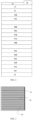
- Table 1 The thicknesses of a 12-junction laser photovoltaic cell using dual-bandgap AlGaAs absorption layers as well as GaAs or Al 0.07 Ga 0.93 As single bandgap absorption lasers to convert 808nm laser.
- FIG. 4 another typical embodiment of the present application relates to a 12-junction InGaAsP laser photovoltaic cell converting 1064 nm laser, including an InP substrate 200, a first tunnel junction 21A, a first InGaAsP subcell 21B, a second tunnel junction 22A, a second InGaAsP subcell 22B, a third tunnel junction 23A, until a sixth InGaAsP subcell 26B; a seventh tunnel junction 27A, a second InGaAsP subcell 27B, an eighth tunnel junction 28A, an eighth InGaAsP subcell 28B, until a twelfth tunnel junction 32A, a twelfth InGaAsP subcell 32B, a current spreading layer 33, a In 0.53 Ga 0.47 As ohmic contact layer 34, a negative electrode 70, an antireflection film 72, a bus 81, a light receiving surface 82 and an electrode grid
- 31B and 32B contain a (Al p1 Ga 1-p1 ) 0.47 In 0.53 As or InP back surface field layer xxB0, an In 0.53 Ga 0.47 As base region xxB1, an In 0.53 Ga 0.47 As emitter region xxB2, an In 0.53 Ga 0.47 As or InP window layer xxB3;
- the first tunnel junction 21A includes (Al z1 Ga 1-z1 ) 0.47 In 0.53 As or InP 21A0 and (Al z1 Ga 1-z1 ) 0.47 In 0.53 As or InP layer 21A1;
- the second tunnel junction to the sixth tunnel junction 22A, 23A...31A and 32A include (Al z1 Ga 1-z1 ) 0.47 In 0.53 As or InP layer xxA0 and (Al z1 Ga 1-z1 ) 0.47 In 0.53 As or InP layer xxA1.
- the method for fabricating the 1064nm InGaAsP laser photovoltaic cell specifically includes the following steps:
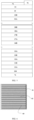
- Table 2 Thicknesses ( ⁇ m) of respective subcell absorption layers in a 1064nm 12-junction laser photovoltaic cell with dual-bandgap InGaAsP and two InGaAsP single bandgap materials as absorption layers Number of cells Dual-bandgap 1.17/1.1eV InGaAsP cell 1.1eV In 0.845 Ga 0.155 As 0.337 P 0.663 cell 1.17 eV In 0.89 Ga 0.11 As 0.24 P 0.76 cell 12 0.1230 0.0615 0.1230 11 0.1346 0.0673 0.1346 10 0.1486 0.0743 0.1486 9 0.1659 0.0829 0.1659 8 0.1877 0.0939 0.1877 7 0.2162 0.1081 0.2162 6 0.1274 0.1274 0.2548 5 0.1552 0.1552 0.3103 4 0.1985 0.1985 0.3970 3 0.2759 0.2759 0.5518 2 0.4554 0.4554 0.9108 1 1.5890 1.5890 3.1780 InP substrate 350 Total thickness of absorption
Landscapes
- Photovoltaic Devices (AREA)
- Life Sciences & Earth Sciences (AREA)
- Engineering & Computer Science (AREA)
- Sustainable Energy (AREA)
- Sustainable Development (AREA)
Claims (9)
- Mehrfachübergang-Laserphotovoltaikzelle zum Umwandeln von Laserenergie in elektrische Energie, umfassendein Substrat (100; 200), einen Zelleinheitskörper, eine obere Elektrode (50; 70) und eine untere Elektrode (51; 71), wobeidie untere Elektrode und die obere Elektrode elektrisch mit einer Unterseite bzw. einer Oberseite des Zelleinheitskörpers verbunden sind, wobeider Zelleinheitskörper eine ohmsche Kontaktschicht (14; 34), eine Stromverteilungsschicht (13; 33), N PN-Übergangsteilzellen (01B ... 12B; 21B ... 32B) und Tunnelübergänge (01A ... 12A; 21A ... 32A) umfasst, wobei die Tunnelübergänge zwischen zwei angrenzenden PN-Übergangsteilzellen der N PN-Übergangsteilzellen eingerichtet sind, und N ≥ 12, dadurch gekennzeichnet, dassdie Teilzellen in zwei Gruppen von der Lichteinfallseite zu der entgegengesetzten Seite der Lichteinfallseite geteilt sind, und jede Gruppe von Teilzellen eine unterschiedliche Bandlücke aufweist und in einer abnehmenden Reihenfolge der Bandlücke von der Lichteinfallseite eingerichtet sinddie photovoltaische Zelle eine AlGaAs-Mehrfachübergangszelle ist, wobei die Absorptionsschicht der 6 Teilzellen an der Unterseite (01B ... 06B) GaAs mit einer Bandlücke von 1,428 eV verwendet, die Absorptionsschicht der 6 Teilzellen an der Oberseite (07B ... 12B)Al0.07Ga0.93As mit einer Bandlücke von 1,515 eV verwendet, oder die photovoltaische Zelle ein InGaAsP-Mehrfachübergang ist, wobei die Absorptionsschicht der 6 Teilzellen an der Unterseite (21B ... 26B) In0,845Ga0,155As0,337P0,663 mit einer Bandlücke von 1,1 eV verwendet, die Absorptionsschicht der 6 Teilzellen auf der Oberseite (27B... 32B) In0,89Ga0,11As0,24P0,76 mit einer Bandlücke von 1,17 eV verwendet.
- Mehrfachübergang-Laserphotovoltaikzelle nach Anspruch 1, wobeieine Lichtabsorptionsschicht in jeder der N PN-Übergangsteilzellen einen Basisbereich und einen Emitterbereich umfasst,der Basisbereich und der Emitterbereich identische Bandlücken aufweisen, undder Basisbereich und der Emitterbereich einen ersten leitenden Typ bzw. einen zweiten leitenden Typ aufweisen, wobeieiner des ersten leitenden Typs und des zweiten leitenden Typs ein leitender n-Typ ist, undder andere des ersten leitenden Typs und des zweiten leitenden Typs ein leitender p-Typ ist.
- Mehrfachübergang-Laserphotovoltaikzelle nach Anspruch 1, wobeijede der N PN-Übergangsteilzellen eine Rückseitenoberflächen-Feldschicht, einen Basisbereich, einen Emitterbereich und eine Fensterschicht umfasst, wobeidie Rückseitenoberflächen-Feldschicht, der Basisbereich, der Emitterbereich und die Fensterschicht nacheinander in einer Einstellrichtung eingerichtet sind,die Rückseitenoberflächen-Feldschicht und der Basisbereich einen ersten leitenden Typ aufweisen,der Emitterbereich und die Fensterschicht einen zweiten leitenden Typ aufweisen, undjede der Rückseitenoberflächen-Feldschicht und der Fensterschicht keinen einfallenden Ziellaser absorbiert.
- Mehrfachübergang-Laserphotovoltaikzelle nach Anspruch 1, wobeidie Tunnelübergänge eine N+-Halbleitermaterialschicht und eine P+-Halbleitermaterialschicht umfassen, wobeidie N+-Halbleitermaterialschicht und die P+-Halbleitermaterialschicht mit einer N-Schicht bzw. einer P-Schicht der zwei angrenzenden PN-Übergangsteilzellen verbunden sind, undjede der N+-Halbleitermaterialschicht und der P+-Halbleitermaterialschicht keinen einfallenden Ziellaser absorbiert.
- Mehrfachübergang-Laserphotovoltaikzelle nach Anspruch 1, wobeidie Stromverteilungsschicht und die ohmsche Kontaktschicht nacheinander auf dem Zelleinheitskörper eingerichtet sind,die ohmsche Kontaktschicht elektrisch mit der oberen Elektrode verbunden ist, unddie Stromverteilungsschicht keinen einfallenden Ziellaser absorbiert.
- Mehrfachübergang-Laserphotovoltaikzelle nach Anspruch 1, wobeidas Substrat ein leitendes Einkristallsubstrat ist, das mit einer Unterseite des Zelleinheitskörpers verbunden ist, und das leitende Einkristallsubstrat elektrisch mit der unteren Elektrode verbunden ist; undein Material des leitenden Einkristallsubstrats GaAs, InP oder Ge umfasst.
- Mehrfachübergang-Laserphotovoltaikzelle nach Anspruch 6, wobei
wenn sich ein leitenden Typ des leitenden Einkristallsubstrats von einem leitenden Typ einer unteren Schicht des Zelleinheitskörpers unterscheidet, ein Tunnelübergang zwischen das leitende Einkristallsubstrat und den Zelleinheitskörper eingefügt wird, um den leitenden Typ des leitenden Einkristallsubstrats umzuschalten. - Mehrfachübergang-Laserphotovoltaikzelle nach Anspruch 1, wobei
eine Dicke jeder der Absorptionsschichten und der N PN-Übergangsteilzellen in dem Zelleinheitskörpers es einem Lichtstrom, der in jeder der N PN-Übergangsteilzellen erzeugt wird, erlaubt, gleich zu sein, wenn die Mehrfachübergang-Laserphotovoltaikzelle ausreichend einfallenden Ziellaser absorbiert. - Mehrfachübergang-Laserphotovoltaikzelle nach Anspruch 1, wobeieine Licht empfangende Oberfläche der Mehrfachübergang-Laserphotovoltaikzelle mit einem Reflexionschutzfilm versehen ist; unddie Licht empfangende Oberfläche eine obere Oberfläche der Mehrfachübergang-Laserphotovoltaikzelle ist.
Applications Claiming Priority (2)
| Application Number | Priority Date | Filing Date | Title |
|---|---|---|---|
| CN201910476086.8A CN112038425B (zh) | 2019-06-03 | 2019-06-03 | 一种多结叠层激光光伏电池 |
| PCT/CN2019/092185 WO2020243998A1 (zh) | 2019-06-03 | 2019-06-21 | 一种多结叠层激光光伏电池 |
Publications (4)
| Publication Number | Publication Date |
|---|---|
| EP3958331A1 EP3958331A1 (de) | 2022-02-23 |
| EP3958331A4 EP3958331A4 (de) | 2022-06-15 |
| EP3958331C0 EP3958331C0 (de) | 2024-08-07 |
| EP3958331B1 true EP3958331B1 (de) | 2024-08-07 |
Family
ID=73576383
Family Applications (1)
| Application Number | Title | Priority Date | Filing Date |
|---|---|---|---|
| EP19931679.5A Active EP3958331B1 (de) | 2019-06-03 | 2019-06-21 | Laminierte laser-fotovoltaikzelle mit mehreren übergängen |
Country Status (4)
| Country | Link |
|---|---|
| US (1) | US11611008B2 (de) |
| EP (1) | EP3958331B1 (de) |
| CN (1) | CN112038425B (de) |
| WO (1) | WO2020243998A1 (de) |
Families Citing this family (5)
| Publication number | Priority date | Publication date | Assignee | Title |
|---|---|---|---|---|
| CN111223880B (zh) * | 2020-03-17 | 2024-06-18 | 福建中科光芯光电科技有限公司 | 一种集成光伏电池结构的红外探测器及其制备方法 |
| CN112713211B (zh) * | 2020-12-29 | 2022-03-15 | 中山德华芯片技术有限公司 | 一种硅基六结太阳电池及其制作方法 |
| CN115548146B (zh) * | 2022-11-28 | 2023-03-24 | 苏州长光华芯光电技术股份有限公司 | 一种激光电池及其制备方法 |
| CN116613220A (zh) * | 2023-05-26 | 2023-08-18 | 昆山工研院新型平板显示技术中心有限公司 | 光伏电池及光伏电池组件 |
| CN119997622B (zh) * | 2025-04-15 | 2025-06-27 | 中国科学院赣江创新研究院 | 一种激光电池阵列芯片 |
Citations (3)
| Publication number | Priority date | Publication date | Assignee | Title |
|---|---|---|---|---|
| JP2008177212A (ja) * | 2007-01-16 | 2008-07-31 | Nec Corp | 半導体受光素子 |
| US20150380591A1 (en) * | 2012-12-21 | 2015-12-31 | Fraunhofer-Gesellschaft zur Förderung der angewandten Forschung e.V. | Adjustment-tolerant photovoltaic cell |
| US20170018675A1 (en) * | 2014-04-11 | 2017-01-19 | Semprius, Inc. | Multi-junction photovoltaic micro-cell architectures for energy harvesting and/or laser power conversion |
Family Cites Families (27)
| Publication number | Priority date | Publication date | Assignee | Title |
|---|---|---|---|---|
| US7119271B2 (en) * | 2001-10-12 | 2006-10-10 | The Boeing Company | Wide-bandgap, lattice-mismatched window layer for a solar conversion device |
| US20030070707A1 (en) * | 2001-10-12 | 2003-04-17 | King Richard Roland | Wide-bandgap, lattice-mismatched window layer for a solar energy conversion device |
| US6660928B1 (en) * | 2002-04-02 | 2003-12-09 | Essential Research, Inc. | Multi-junction photovoltaic cell |
| US7122733B2 (en) * | 2002-09-06 | 2006-10-17 | The Boeing Company | Multi-junction photovoltaic cell having buffer layers for the growth of single crystal boron compounds |
| US7126052B2 (en) * | 2002-10-02 | 2006-10-24 | The Boeing Company | Isoelectronic surfactant induced sublattice disordering in optoelectronic devices |
| US7812249B2 (en) * | 2003-04-14 | 2010-10-12 | The Boeing Company | Multijunction photovoltaic cell grown on high-miscut-angle substrate |
| US7488890B2 (en) * | 2003-04-21 | 2009-02-10 | Sharp Kabushiki Kaisha | Compound solar battery and manufacturing method thereof |
| WO2005020334A2 (en) * | 2003-08-22 | 2005-03-03 | Massachusetts Institute Of Technology | High efficiency tandem solar cells on silicon substrates using ultra thin germanium buffer layers |
| JP5248782B2 (ja) * | 2004-01-20 | 2013-07-31 | シリアム・テクノロジーズ・インコーポレーテッド | エピタキシャルに成長させた量子ドット材料を有する太陽電池 |
| US20050247339A1 (en) * | 2004-05-10 | 2005-11-10 | Imperial College Innovations Limited | Method of operating a solar cell |
| US20060180198A1 (en) * | 2005-02-16 | 2006-08-17 | Sharp Kabushiki Kaisha | Solar cell, solar cell string and method of manufacturing solar cell string |
| US20090078309A1 (en) * | 2007-09-24 | 2009-03-26 | Emcore Corporation | Barrier Layers In Inverted Metamorphic Multijunction Solar Cells |
| US20090078311A1 (en) * | 2007-09-24 | 2009-03-26 | Emcore Corporation | Surfactant Assisted Growth in Barrier Layers In Inverted Metamorphic Multijunction Solar Cells |
| US8822817B2 (en) * | 2010-12-03 | 2014-09-02 | The Boeing Company | Direct wafer bonding |
| US10170652B2 (en) * | 2011-03-22 | 2019-01-01 | The Boeing Company | Metamorphic solar cell having improved current generation |
| CN103022057A (zh) * | 2011-09-21 | 2013-04-03 | 索尼公司 | 多结太阳能电池、光电转换元件和化合物半导体层叠层结构体 |
| CN103022058A (zh) * | 2011-09-21 | 2013-04-03 | 索尼公司 | 多结太阳能电池、化合物半导体器件、光电转换元件和化合物半导体层叠层结构体 |
| CN103219919A (zh) * | 2012-01-18 | 2013-07-24 | 王广武 | 激光照射光电或光热转换装置及方法 |
| CN103337548B (zh) * | 2013-06-19 | 2016-12-07 | 中国科学院苏州纳米技术与纳米仿生研究所 | 含Bi热光伏电池的结构及其制备方法 |
| US10158037B2 (en) * | 2013-12-09 | 2018-12-18 | Avago Technologies International Sales Pte. Limited | Transducer to convert optical energy to electrical energy |
| CN105514207B (zh) * | 2015-12-08 | 2017-04-26 | 天津三安光电有限公司 | 一种多结太阳能电池的集成旁路二极管的制备方法 |
| DE102015016822B4 (de) * | 2015-12-25 | 2023-01-05 | Azur Space Solar Power Gmbh | Stapelförmige Mehrfach-Solarzelle |
| CN107093647A (zh) * | 2017-04-06 | 2017-08-25 | 江苏中天科技股份有限公司 | 激光光伏电池及其制备方法 |
| CN108735848B (zh) * | 2017-04-17 | 2020-09-01 | 中国科学院苏州纳米技术与纳米仿生研究所 | 多结叠层激光光伏电池及其制作方法 |
| CN108987521B (zh) * | 2017-05-31 | 2022-02-08 | 安华高科技股份有限公司 | 将光能转换为电能的换能器 |
| WO2018232524A1 (en) * | 2017-06-23 | 2018-12-27 | University Of Ottawa | Photovoltaic device |
| US12249666B2 (en) * | 2018-12-11 | 2025-03-11 | The Boeing Company | Use of a low bandgap absorber region in a laser power converter |
-
2019
- 2019-06-03 CN CN201910476086.8A patent/CN112038425B/zh active Active
- 2019-06-21 US US17/428,640 patent/US11611008B2/en active Active
- 2019-06-21 WO PCT/CN2019/092185 patent/WO2020243998A1/zh not_active Ceased
- 2019-06-21 EP EP19931679.5A patent/EP3958331B1/de active Active
Patent Citations (3)
| Publication number | Priority date | Publication date | Assignee | Title |
|---|---|---|---|---|
| JP2008177212A (ja) * | 2007-01-16 | 2008-07-31 | Nec Corp | 半導体受光素子 |
| US20150380591A1 (en) * | 2012-12-21 | 2015-12-31 | Fraunhofer-Gesellschaft zur Förderung der angewandten Forschung e.V. | Adjustment-tolerant photovoltaic cell |
| US20170018675A1 (en) * | 2014-04-11 | 2017-01-19 | Semprius, Inc. | Multi-junction photovoltaic micro-cell architectures for energy harvesting and/or laser power conversion |
Also Published As
| Publication number | Publication date |
|---|---|
| EP3958331C0 (de) | 2024-08-07 |
| US20220020890A1 (en) | 2022-01-20 |
| EP3958331A1 (de) | 2022-02-23 |
| CN112038425A (zh) | 2020-12-04 |
| WO2020243998A1 (zh) | 2020-12-10 |
| EP3958331A4 (de) | 2022-06-15 |
| CN112038425B (zh) | 2024-04-30 |
| US11611008B2 (en) | 2023-03-21 |
Similar Documents
| Publication | Publication Date | Title |
|---|---|---|
| EP3958331B1 (de) | Laminierte laser-fotovoltaikzelle mit mehreren übergängen | |
| US5391896A (en) | Monolithic multi-color light emission/detection device | |
| US20130133730A1 (en) | Thin film inp-based solar cells using epitaxial lift-off | |
| US6888179B2 (en) | GaAs substrate with Sb buffering for high in devices | |
| US8933326B2 (en) | Multijunction compound semiconductor solar cell | |
| US8822817B2 (en) | Direct wafer bonding | |
| US20100093127A1 (en) | Inverted Metamorphic Multijunction Solar Cell Mounted on Metallized Flexible Film | |
| JP2010118666A (ja) | 反転変性多接合太陽電池の代替基板 | |
| US9214594B2 (en) | Fabrication of solar cells with electrically conductive polyimide adhesive | |
| EP3614444B1 (de) | Mehrschichtige laminierte laserfotovoltaische zelle und herstellungsverfahren dafür | |
| JP6536220B2 (ja) | 化合物半導体太陽電池及びその製造方法 | |
| US10026856B2 (en) | Systems and methods for advanced ultra-high-performance InP solar cells | |
| CN107546293B (zh) | 双结太阳能电池及其制备方法、太阳能电池外延结构 | |
| JP6404282B2 (ja) | 多接合反転変成ソーラーセル | |
| CN114566560B (zh) | 一种砷化镓激光光伏电池及其制备方法 | |
| KR101460915B1 (ko) | 다중접합 태양 전지의 분리 방법 및 이에 따라 제조된 다중접합 태양 전지 구조 | |
| US20190035965A1 (en) | Group iii-v compound semiconductor solar cell, method of manufacturing group iii-v compound semiconductor solar cell, and artificial satellite | |
| US20220020891A1 (en) | Systems and Methods for Three-Terminal Tandem Solar Cells | |
| KR20190109097A (ko) | 화합물 반도체 태양전지의 제조 방법 |
Legal Events
| Date | Code | Title | Description |
|---|---|---|---|
| STAA | Information on the status of an ep patent application or granted ep patent |
Free format text: STATUS: THE INTERNATIONAL PUBLICATION HAS BEEN MADE |
|
| PUAI | Public reference made under article 153(3) epc to a published international application that has entered the european phase |
Free format text: ORIGINAL CODE: 0009012 |
|
| STAA | Information on the status of an ep patent application or granted ep patent |
Free format text: STATUS: REQUEST FOR EXAMINATION WAS MADE |
|
| 17P | Request for examination filed |
Effective date: 20211118 |
|
| AK | Designated contracting states |
Kind code of ref document: A1 Designated state(s): AL AT BE BG CH CY CZ DE DK EE ES FI FR GB GR HR HU IE IS IT LI LT LU LV MC MK MT NL NO PL PT RO RS SE SI SK SM TR |
|
| REG | Reference to a national code |
Ref country code: DE Ref legal event code: R079 Free format text: PREVIOUS MAIN CLASS: H01L0031030400 Ipc: H01L0031068700 Ref country code: DE Ref legal event code: R079 Ref document number: 602019056823 Country of ref document: DE Free format text: PREVIOUS MAIN CLASS: H01L0031030400 Ipc: H01L0031068700 |
|
| A4 | Supplementary search report drawn up and despatched |
Effective date: 20220517 |
|
| RIC1 | Information provided on ipc code assigned before grant |
Ipc: H01L 31/0304 20060101ALI20220511BHEP Ipc: H01L 31/0693 20120101ALI20220511BHEP Ipc: H01L 31/0687 20120101AFI20220511BHEP |
|
| DAV | Request for validation of the european patent (deleted) | ||
| DAX | Request for extension of the european patent (deleted) | ||
| STAA | Information on the status of an ep patent application or granted ep patent |
Free format text: STATUS: EXAMINATION IS IN PROGRESS |
|
| 17Q | First examination report despatched |
Effective date: 20220926 |
|
| GRAP | Despatch of communication of intention to grant a patent |
Free format text: ORIGINAL CODE: EPIDOSNIGR1 |
|
| STAA | Information on the status of an ep patent application or granted ep patent |
Free format text: STATUS: GRANT OF PATENT IS INTENDED |
|
| INTG | Intention to grant announced |
Effective date: 20240425 |
|
| GRAS | Grant fee paid |
Free format text: ORIGINAL CODE: EPIDOSNIGR3 |
|
| GRAA | (expected) grant |
Free format text: ORIGINAL CODE: 0009210 |
|
| STAA | Information on the status of an ep patent application or granted ep patent |
Free format text: STATUS: THE PATENT HAS BEEN GRANTED |
|
| AK | Designated contracting states |
Kind code of ref document: B1 Designated state(s): AL AT BE BG CH CY CZ DE DK EE ES FI FR GB GR HR HU IE IS IT LI LT LU LV MC MK MT NL NO PL PT RO RS SE SI SK SM TR |
|
| REG | Reference to a national code |
Ref country code: GB Ref legal event code: FG4D |
|
| REG | Reference to a national code |
Ref country code: CH Ref legal event code: EP |
|
| REG | Reference to a national code |
Ref country code: IE Ref legal event code: FG4D |
|
| REG | Reference to a national code |
Ref country code: DE Ref legal event code: R096 Ref document number: 602019056823 Country of ref document: DE |
|
| U01 | Request for unitary effect filed |
Effective date: 20240812 |
|
| U07 | Unitary effect registered |
Designated state(s): AT BE BG DE DK EE FI FR IT LT LU LV MT NL PT SE SI Effective date: 20240827 |
|
| PG25 | Lapsed in a contracting state [announced via postgrant information from national office to epo] |
Ref country code: NO Free format text: LAPSE BECAUSE OF FAILURE TO SUBMIT A TRANSLATION OF THE DESCRIPTION OR TO PAY THE FEE WITHIN THE PRESCRIBED TIME-LIMIT Effective date: 20241107 |
|
| PG25 | Lapsed in a contracting state [announced via postgrant information from national office to epo] |
Ref country code: PL Free format text: LAPSE BECAUSE OF FAILURE TO SUBMIT A TRANSLATION OF THE DESCRIPTION OR TO PAY THE FEE WITHIN THE PRESCRIBED TIME-LIMIT Effective date: 20240807 Ref country code: GR Free format text: LAPSE BECAUSE OF FAILURE TO SUBMIT A TRANSLATION OF THE DESCRIPTION OR TO PAY THE FEE WITHIN THE PRESCRIBED TIME-LIMIT Effective date: 20241108 |
|
| PG25 | Lapsed in a contracting state [announced via postgrant information from national office to epo] |
Ref country code: IS Free format text: LAPSE BECAUSE OF FAILURE TO SUBMIT A TRANSLATION OF THE DESCRIPTION OR TO PAY THE FEE WITHIN THE PRESCRIBED TIME-LIMIT Effective date: 20241207 |
|
| PG25 | Lapsed in a contracting state [announced via postgrant information from national office to epo] |
Ref country code: HR Free format text: LAPSE BECAUSE OF FAILURE TO SUBMIT A TRANSLATION OF THE DESCRIPTION OR TO PAY THE FEE WITHIN THE PRESCRIBED TIME-LIMIT Effective date: 20240807 |
|
| PG25 | Lapsed in a contracting state [announced via postgrant information from national office to epo] |
Ref country code: ES Free format text: LAPSE BECAUSE OF FAILURE TO SUBMIT A TRANSLATION OF THE DESCRIPTION OR TO PAY THE FEE WITHIN THE PRESCRIBED TIME-LIMIT Effective date: 20240807 Ref country code: RS Free format text: LAPSE BECAUSE OF FAILURE TO SUBMIT A TRANSLATION OF THE DESCRIPTION OR TO PAY THE FEE WITHIN THE PRESCRIBED TIME-LIMIT Effective date: 20241107 |
|
| PG25 | Lapsed in a contracting state [announced via postgrant information from national office to epo] |
Ref country code: RS Free format text: LAPSE BECAUSE OF FAILURE TO SUBMIT A TRANSLATION OF THE DESCRIPTION OR TO PAY THE FEE WITHIN THE PRESCRIBED TIME-LIMIT Effective date: 20241107 Ref country code: PL Free format text: LAPSE BECAUSE OF FAILURE TO SUBMIT A TRANSLATION OF THE DESCRIPTION OR TO PAY THE FEE WITHIN THE PRESCRIBED TIME-LIMIT Effective date: 20240807 Ref country code: NO Free format text: LAPSE BECAUSE OF FAILURE TO SUBMIT A TRANSLATION OF THE DESCRIPTION OR TO PAY THE FEE WITHIN THE PRESCRIBED TIME-LIMIT Effective date: 20241107 Ref country code: IS Free format text: LAPSE BECAUSE OF FAILURE TO SUBMIT A TRANSLATION OF THE DESCRIPTION OR TO PAY THE FEE WITHIN THE PRESCRIBED TIME-LIMIT Effective date: 20241207 Ref country code: HR Free format text: LAPSE BECAUSE OF FAILURE TO SUBMIT A TRANSLATION OF THE DESCRIPTION OR TO PAY THE FEE WITHIN THE PRESCRIBED TIME-LIMIT Effective date: 20240807 Ref country code: GR Free format text: LAPSE BECAUSE OF FAILURE TO SUBMIT A TRANSLATION OF THE DESCRIPTION OR TO PAY THE FEE WITHIN THE PRESCRIBED TIME-LIMIT Effective date: 20241108 Ref country code: ES Free format text: LAPSE BECAUSE OF FAILURE TO SUBMIT A TRANSLATION OF THE DESCRIPTION OR TO PAY THE FEE WITHIN THE PRESCRIBED TIME-LIMIT Effective date: 20240807 |
|
| PG25 | Lapsed in a contracting state [announced via postgrant information from national office to epo] |
Ref country code: SM Free format text: LAPSE BECAUSE OF FAILURE TO SUBMIT A TRANSLATION OF THE DESCRIPTION OR TO PAY THE FEE WITHIN THE PRESCRIBED TIME-LIMIT Effective date: 20240807 |
|
| PG25 | Lapsed in a contracting state [announced via postgrant information from national office to epo] |
Ref country code: CZ Free format text: LAPSE BECAUSE OF FAILURE TO SUBMIT A TRANSLATION OF THE DESCRIPTION OR TO PAY THE FEE WITHIN THE PRESCRIBED TIME-LIMIT Effective date: 20240807 |
|
| PG25 | Lapsed in a contracting state [announced via postgrant information from national office to epo] |
Ref country code: SK Free format text: LAPSE BECAUSE OF FAILURE TO SUBMIT A TRANSLATION OF THE DESCRIPTION OR TO PAY THE FEE WITHIN THE PRESCRIBED TIME-LIMIT Effective date: 20240807 |
|
| PLBE | No opposition filed within time limit |
Free format text: ORIGINAL CODE: 0009261 |
|
| STAA | Information on the status of an ep patent application or granted ep patent |
Free format text: STATUS: NO OPPOSITION FILED WITHIN TIME LIMIT |
|
| U20 | Renewal fee for the european patent with unitary effect paid |
Year of fee payment: 7 Effective date: 20250528 |
|
| 26N | No opposition filed |
Effective date: 20250508 |
|
| REG | Reference to a national code |
Ref country code: CH Ref legal event code: H13 Free format text: ST27 STATUS EVENT CODE: U-0-0-H10-H13 (AS PROVIDED BY THE NATIONAL OFFICE) Effective date: 20260127 |
|
| PG25 | Lapsed in a contracting state [announced via postgrant information from national office to epo] |
Ref country code: MC Free format text: LAPSE BECAUSE OF FAILURE TO SUBMIT A TRANSLATION OF THE DESCRIPTION OR TO PAY THE FEE WITHIN THE PRESCRIBED TIME-LIMIT Effective date: 20240807 |