EP3957595B1 - Kransteuerung zur automatisierten ansteuerung von kran-stellwerken - Google Patents
Kransteuerung zur automatisierten ansteuerung von kran-stellwerken Download PDFInfo
- Publication number
- EP3957595B1 EP3957595B1 EP21168861.9A EP21168861A EP3957595B1 EP 3957595 B1 EP3957595 B1 EP 3957595B1 EP 21168861 A EP21168861 A EP 21168861A EP 3957595 B1 EP3957595 B1 EP 3957595B1
- Authority
- EP
- European Patent Office
- Prior art keywords
- crane
- target position
- positioner
- control system
- crane control
- Prior art date
- Legal status (The legal status is an assumption and is not a legal conclusion. Google has not performed a legal analysis and makes no representation as to the accuracy of the status listed.)
- Active
Links
Images
Classifications
-
- B—PERFORMING OPERATIONS; TRANSPORTING
- B66—HOISTING; LIFTING; HAULING
- B66C—CRANES; LOAD-ENGAGING ELEMENTS OR DEVICES FOR CRANES, CAPSTANS, WINCHES, OR TACKLES
- B66C23/00—Cranes comprising essentially a beam, boom, or triangular structure acting as a cantilever and mounted for translatory of swinging movements in vertical or horizontal planes or a combination of such movements, e.g. jib-cranes, derricks, tower cranes
- B66C23/62—Constructional features or details
- B66C23/82—Luffing gear
-
- B—PERFORMING OPERATIONS; TRANSPORTING
- B66—HOISTING; LIFTING; HAULING
- B66C—CRANES; LOAD-ENGAGING ELEMENTS OR DEVICES FOR CRANES, CAPSTANS, WINCHES, OR TACKLES
- B66C13/00—Other constructional features or details
- B66C13/18—Control systems or devices
-
- B—PERFORMING OPERATIONS; TRANSPORTING
- B66—HOISTING; LIFTING; HAULING
- B66C—CRANES; LOAD-ENGAGING ELEMENTS OR DEVICES FOR CRANES, CAPSTANS, WINCHES, OR TACKLES
- B66C13/00—Other constructional features or details
- B66C13/18—Control systems or devices
- B66C13/48—Automatic control of crane drives for producing a single or repeated working cycle; Program control
Definitions
- the present invention relates to a crane control system which controls one or more signal boxes of a crane in such a way that the signal box or boxes in question are moved to a desired target position without the crane operator having to enter corresponding control commands.
- Cranes in general and mobile cranes in particular have a large number of signal boxes to carry out the necessary crane movements, which are connected to an operating device for the crane operator via a crane control system. Control commands entered by the crane operator via the operating device are thus converted by the crane control system into corresponding signals for the signal boxes.
- the same adjustment movements must always be carried out to move the crane from a transport configuration to an operating configuration or from an operating configuration back to the transport configuration.
- these adjustment movements must be carried out in reverse order to prepare the crane for road transport.
- the WO 2015/113084 A1 discloses a crane control for a crane with a first and a second operating mode, wherein in the second operating mode the Crane geometry can be changed in a predetermined sequence of movements by the crane control.
- the WO 2015/113084 A1 discloses a crane control according to the preamble of independent claim 1.
- the EP 3 556 709 A1 discloses a system for the automatic movement of a crane articulated arm.
- the EN 10 2016 015 388 A1 discloses a method for assisted execution of crane movements of a crane with at least two boom elements that can be moved relative to one another.
- WO 2015/021558 A1 discloses a system and a method for operating a crane, wherein previous movement sequences of the crane can be repeated.
- the present invention has the object of relieving the crane operator's workload. This object is achieved by the subject matter of independent claim 1 and the subordinate claim 8.
- the crane control according to the invention only receives an input from the crane operator with which he gives the crane control a release to send control signals to one or more signal boxes so that they move to a predefined target position.
- the crane control system receives a target position to be approached from at least one signal box before it receives the release from the crane operator to use control signals to cause the corresponding signal boxes to approach the desired target position.
- the control of signal boxes on a crane superstructure is just as conceivable as the control of signal boxes on a crane undercarriage.
- this would particularly include support and/or sliding cylinders on a crane support.
- a desired support beam position could be preselected via user input, which is then moved to by the sliding cylinders of the support beams.
- the support cylinders can then extend automatically and the vehicle can be leveled. The release for this could be made, for example, by continuously pressing a button on a keypad.
- target position used here should be understood in the case of cable drums, hydraulic motors and similar control systems that pass through individual positions many times to mean that the elements influenced by them, such as cables or liquid volumes, are operated in the desired manner. In the case of cable drums, this does not mean the absolute angular position of the cable drum itself, but rather the desired length of cable wound up or unwound.
- the transport position of a crane boom to be provided for road transport defines a target position of at least one signal box.
- the target position or the data describing it can be permanently stored in the crane control system, for example on a non-volatile storage medium.
- a ready-to-use position of the crane boom defines a target position of at least one signal box. While the target positions required for such a ready-to-use position of the crane boom or the data describing them are also permanently stored in the crane control system It is also conceivable that the crane control system provides the option of user-defined target positions for one or more signal boxes. For example, several crane operators can define different, preferred positions of the crane boom as the preferred operational position to which the crane boom should automatically move at the start of use.
- the crane control defines a target position of at least one signal box based on a user input, which is entered, for example, via an operating device. It is conceivable that the crane operator first enters the desired values for the luffing angle, the swivel angle, the telescoping length and/or the hoist rope length via a keypad or similar operating elements.
- the current position of at least one signal box can be defined as a target position, for example by the crane operator pressing a button. In this way, a specific boom position can be approached exactly again at a later point in time.
- the crane operator can, so to speak, readjust a previously defined target position, which is particularly advantageous if the crane's environment changes or develops during use.
- the second case it is possible to interrupt the predefined approach to the target position and resume it at any later time.
- the present invention provides that the crane control system only outputs the control data as long as the user operates an operating device.
- a control element is permanently must be operated, for example a joystick must be permanently swiveled in any direction or in a predefined direction.
- the direction of operation of the control element does not necessarily have to match the direction of the actuating movement to be carried out by the control box.
- the crane operator can permanently "pull" a joystick, whereby the crane boom moves towards the desired target position as long as the joystick remains pulled. As soon as the operating element or joystick is released, the crane control stops the actuating movements.
- At least one second signal box is controlled automatically by the crane control in parallel in the manner described above, i.e. without any specific control by the crane operator.
- the crane operator can use the operating device to control the telescoping cylinder to extend or retract the boom in a conventional manner, while the hoist cable winch is automatically controlled by the crane control in such a way that the hoist cable is wound up or unwound according to the length of the boom.
- the "target position" for the hoist winch can therefore be defined by the hoist cable length that is necessary to keep the hook block at a predefined distance from the boom head.
- the crane control can update a target position of at least one signal box continuously or at predetermined time intervals.
- the deflection of the crane boom and/or the position of the load can be taken into account here.
- the current target position can depend purely on the position of the signal boxes directly controlled by the crane operator.
- the target position of the hoist winch can depend on the position of the luffing cylinder and/or the telescoping length.
- the crane control records the actuation of at least one signal box, in particular a sequence of the actuation of several signal boxes over a time interval.
- the recorded signal box actuations can then be converted by the crane control into corresponding control signals at a later point in time in order to actuate the signal box or boxes again in an identical manner.
- the present invention further relates to a crane, in particular a mobile crane, which comprises a crane control according to one of the embodiments described above.
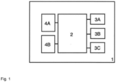
- the Figure 1 shows a block diagram of a mobile crane 1, which comprises a crane control 2 according to the present invention.
- the crane control 2 is connected on the one hand to a keypad 4A and a joystick 4B, which together form a human-machine interface 4 of the mobile crane 1.
- the crane control 2 is connected to several control boxes 3A, 3B, 3C of the mobile crane 1.
- the block 3A represents a telescoping cylinder, the block 3B a luffing cylinder and the block 3C the hoist of the mobile crane 1.
- the crane control 2 enables automatic assembly and disassembly of the crane 1.
- the telescopic boom of the Crane 1 can be brought from a transport position supported on the crane undercarriage into an operational position with predefined values for the luffing angle, the swivel angle and the telescoping length by the crane operator simply "pulling" the control stick 4B.
- the predefined values for the luffing angle, the swivel angle and the telescoping length can, for example, be stored in a non-volatile memory of the crane control 2, or can be entered beforehand by the crane operator via the keypad 4A.
- the rigging movement can be defined in such a way that the crane boom is first raised from its support block on the crane undercarriage by actuating the luffing cylinder 3B and brought to a predefined luffing angle.
- the crane control 2 can then control an undesignated slewing gear on the crane uppercarriage, which brings the crane boom to a predefined swivel angle.
- the crane control can then actuate the telescoping cylinder 3A and an associated locking head in such a way that the crane boom is telescoped out to a predefined telescoping length.
- the crane control 2 controls the hoist 3C in such a way that the crane hook block is held in a constant position relative to the boom head.
- Adjustment movements of the telescoping cylinder 3A, the luffing cylinder 3B and the Figure 1 The rotation of the rotating mechanism (not shown) can take place in parallel, at least in sections.
- the crane operator To dismantle the crane from any position of the crane boom into a transport position supported on the crane undercarriage, the crane operator only needs to pull the joystick 4B so that the crane control 2 controls the respective signal boxes 3A, 3B and 3C in such a way that they accept the control values for the transport position stored in the non-volatile memory.
- the crane control enables a crane operator to start a recording mode using the keypad 4A, so that the signal box movements he causes using the joystick 4B are recorded.
- the crane operator can, for example, in a playback mode started via an input on the keypad 4A, cause the crane control 2 to play back the previously recorded signal box movements - starting from a recorded starting point. This relieves the crane operator of the task of controlling recurring signal box movements.
- the crane operator can enter a desired target lifting height of the load attached to the boom via the keypad 4A or define a currently prevailing load lifting height as the target lifting height. While the crane operator then initiates any adjustment movements of the telescoping cylinder 3A and the luffing cylinder 3B, the crane control 2 always adjusts the crane hook block by automatically operating the hoist 3C so that the previously defined height of the load relative to the ground or the crane undercarriage remains constant.
Landscapes
- Engineering & Computer Science (AREA)
- Mechanical Engineering (AREA)
- Automation & Control Theory (AREA)
- Control And Safety Of Cranes (AREA)
- Jib Cranes (AREA)
Description
- Die vorliegende Erfindung betrifft eine Kransteuerung, welche ein oder mehrere Stellwerke eines Krans dergestalt ansteuert, dass das oder die betreffenden Stellwerke in eine gewünschte Soll-Stellung verbracht werden, ohne dass es hierfür einer Eingabe von entsprechenden Steuerbefehlen seitens des Kranführers bedarf.
- Krane im Allgemeinen und Mobilkrane im Speziellen weisen zur Durchführung notwendiger Kranbewegungen eine Vielzahl von Stellwerken auf, welche über eine Kransteuerung mit einer Bedieneinrichtung für den Kranführer verbunden sind. Vom Kranführer über die Bedieneinrichtung eingegebene Steuerbefehle werden somit von der Kransteuerung in entsprechende Signale für die Stellwerke gewandelt.
- Beispielsweise zu Beginn und am Ende des Einsatzes sind stets die gleichen Stellbewegungen auszuführen, um den Kran von einer Transport-Konfiguration in eine Betriebs-Konfiguration bzw. von einer Betriebs-Konfiguration wieder in die Transport-Konfiguration zu überführen. Am Einsatzort angekommen, wird zunächst die Hakenflasche vom vorderen Zugmaul am Unterwagens gelöst, woraufhin der Teleskopausleger durch Einwippen aus dem Auflagebock am Unterwagen gehoben wird. Erst danach kann die Hakenflasche durch Verschwenken und Teleskopieren des Auslegers in eine gewünschte Position oberhalb einer zu hebenden Last gebracht werden. Hierbei muss das Hubseil bzw. die Hakenflasche entsprechend nachgeführt werden. Am Einsatzende sind diese Stellbewegungen in umgekehrter Reihenfolge durchzuführen, um den Kran für den Straßentransport vorzubereiten.
- Sowohl die strikte Einhaltung vorbestimmter Abfolgen von Stellbewegungen, wie auch stets wiederkehrende Stellbewegungen in vorbestimmte Positionen bedeuten eine nicht unerhebliche Beanspruchung für den Kranführer.
- Die
WO 2015/113084 A1 offenbart eine Kransteuerung für einen Kran mit einem ersten und einem zweiten Betriebsmodus, wobei im zweiten Betriebsmodus die Krangeometrie in einer vorbestimmten Abfolge von Bewegungen durch die Kransteuerung veränderbar ist. DieWO 2015/113084 A1 offenbart eine Kransteuerung gemäß dem Oberbegriff des unabhängigen Anspruchs 1. - Die
EP 3 556 709 A1 offenbart ein System zur automatischen Bewegung eines Kran-Gelenkarmes. DieDE 10 2016 015 388 A1 offenbart ein Verfahren zur assistierten Ausführung von Kranbewegungen eines Krans mit wenigstens zwei relativ zueinander bewegbaren Auslegerelementen. DieWO 2015/021558 A1 offenbart ein System und ein Verfahren für den Betrieb eines Kranes, wobei vorherige Bewegungsabläufe des Krans erneut durchlaufen werden können. - Die vorliegende Erfindung hat die Aufgabe, hier eine Entlastung des Kranführers zu schaffen. Diese Aufgabe wird durch den Gegenstand des unabhängigen Anspruchs 1 und des nebengeordneten Anspruchs 8 gelöst.
- Die erfindungsgemäße Kransteuerung zur Ansteuerung von Stellwerken eines Krans ist demnach dazu ausgestaltet, die folgenden Funktionen durchzuführen:
- Empfangen von Sollstellungs-Daten, welche eine vordefinierte Soll-Stellung zumindest eines Stellwerks, insbesondere zumindest eines Kranoberwagen-Stellwerks beschreiben;
- Empfangen von Freigabe-Daten, welche eine Benutzereingabe zur Freigabe einer Bewegung des zumindest einen Stellwerks in die vordefinierte Soll-Stellung beschreiben;
- Ausgeben von Steuerungs-Daten, welche an das zumindest eine Stellwerk abzugebende Steuersignale beschreiben, um das zumindest eine Stellwerk in die vordefinierte Soll-Stellung zu verbringen, wobei die Steuerungs-Daten solange ausgegeben werden, wie eine Bedienungseinrichtung vom Benutzer zur Betätigung zumindest eines weiteren Stellwerks betätigt wird.
- Im Unterschied zu bekannten Kransteuerungen, welche die vom Kranführer über eine Bedienungseinrichtung eingegebenen Steuerbefehle zeitecht es in eine entsprechende Ansteuerung bzw. Steuersignale für die betreffenden Stellwerke wandelt, empfängt die erfindungsgemäße Kransteuerung vom Kranführer lediglich eine Eingabe, mit welcher er eine Freigabe für die Kransteuerung erteilt, Steuersignale an ein oder mehrere Stellwerke abzugeben, sodass diese eine vordefinierte Soll-Stellung anfahren.
- Wieder anders ausgedrückt empfängt die erfindungsgemäße Kransteuerung vom zumindest einen Stellwerk eine anzufahrende Soll-Stellung, bevor sie vom Kranführer die Freigabe dazu erhält, mittels Steuersignalen die entsprechenden Stellwerke dazu zu veranlassen, die gewünschte Sollstellung anzufahren.
- Grundsätzlich ist im Rahmen der vorliegenden Erfindung die Ansteuerung von Stellwerken eines Kran-Oberwagens ebenso vorstellbar wie die Ansteuerung von Stellwerken eines Kran-Unterwagens. Im zweiteren Falle wäre hier insbesondere an Abstütz- und/oder Schiebezylinder einer Kranabstützung zu denken. In einer speziellen Ausführungsform könnte hier über eine Benutzereingabe eine gewünschte Abstützträgerposition vorgewählt werden, welche anschließend von den Schiebezylindern der Abstützträger angefahren wird. Die Abstützzylinder können so dann automatisch ausfahren und das Fahrzeug nivelliert werden. Die Freigabe hierzu könnte beispielsweise über eine dauerhafte Tastenbetätigung an einem Tastenfeld erfolgen.
- Der hier verwendete Ausdruck "Soll-Stellung" soll im Falle von Seiltrommeln, Hydromotoren und ähnlichen, einzelne Positionen vielfach durchlaufenden Stellwerken so verstanden werden, dass die hiervon beeinflussten Elemente wie etwa Seile oder Flüssigkeitsvolumina in gewünschter Weise betätigt werden. Hier ist im Falle von Seiltrommeln nicht die absolute Winkelstellung der Seiltrommel selbst zu verstehen, sondern vielmehr die gewünschte auf- bzw. abgetrommelte Seillänge.
- Gemäß einer Ausführungsform der vorliegenden Erfindung definiert die für den Straßentransport vorzusehende Transportstellung eines Kranauslegers eine Soll-Stellung zumindest eines Stellwerks. Für diesen und ähnliche Fälle kann die Soll-Stellung bzw. die diese beschreibenden Daten fest in der Kransteuerung hinterlegt sein, beispielsweise auf einem nicht-flüchtigen Speichermedium.
- Gemäß einer weiteren Ausführungsform definiert eine betriebsfertige Stellung des Kranauslegers eine Soll-Stellung zumindest eines Stellwerks. Während die für eine solche betriebsfertige Stellung des Kranauslegers notwendigen Soll-Stellungen bzw. die diese beschreibenden Daten ebenfalls fest in der Kransteuerung hinterlegt sein können, ist es hierbei ferner denkbar, dass die Kransteuerung die Möglichkeit benutzerdefinierter Soll-Stellungen eines oder mehrerer Stellwerke bereitstellt. So können beispielsweise von mehreren Kranführern unterschiedliche, bevorzugte Stellungen des Kranauslegers als bevorzugte betriebsfertige Stellung definiert werden, in welche der Kranausleger zum Einsatzbeginn automatisch verfahren soll.
- Gemäß einer weiteren Ausführungsform der vorliegenden Erfindung definiert also die Kransteuerung eine Soll-Stellung zumindest eines Stellwerks auf Basis einer Benutzereingabe, welche beispielsweise über eine Bedienungseinrichtung eingegeben wird. Es ist denkbar, dass der Kranführer zunächst die gewünschten Werte für den Wippwinkel, den Schwenkwinkel, die Teleskopierlänge und/oder die Hubseillänge über ein Tastenfeld oder ähnliche Bedienelemente eingibt. Andererseits kann die aktuelle Stellung zumindest eines Stellwerks als Soll-Stellung definiert werden, beispielsweise über einen Tastendruck des Kranführers. So kann eine bestimmte Auslegerstellung zu einem späteren Zeitpunkt wieder exakt angefahren werden.
- Ferner ist es vorstellbar, dass die Kransteuerung
- eine Benutzereingabe zur Abänderung der Soll-Stellung ermöglicht, insbesondere wobei die abgeänderte Stellung als neue Soll-Stellung definiert wird; und/oder
- eine Benutzereingabe zum Abbruch des Anfahrens der Soll-Stellung ermöglicht, insbesondere wobei zur Wiederaufnahme des Anfahrens der Soll-Stellung das zumindest eine Stellwerk in seine Position zum Zeitpunkt des Abbruchs verbracht wird.
- Im ersten Fall kann der Kranführer sozusagen eine vormals definierte Soll-Stellung nachjustieren, was insbesondere dann von Vorteil ist, wenn sich das Umfeld des Krans während des Einsatzes ändert bzw. fortentwickelt. Im zweiten Fall ist es möglich, das vordefinierte Anfahren der Soll-Stellung zu unterbrechen und zu einem beliebigen späteren Zeitpunkt wiederaufzunehmen.
- Die vorliegende Erfindung sieht vor, dass die Kransteuerung die Steuerungs-Daten nur solange ausgibt, wie der Benutzer eine Bedienungseinrichtung betätigt. Hierfür ist es vorstellbar, dass zur Ausführung der Stellbewegungen ein Bedienelement dauerhaft betätigt werden muss, beispielsweise ein Steuerknüppel dauerhaft in eine beliebige oder in vordefinierte Richtung verschwenkt werden muss. Dem Wesen der vorliegenden Erfindung entsprechend muss die Betätigungsrichtung des Steuerelements nicht notwendigerweise mit der Richtung der vom Stellwerk zu vollziehenden Stellbewegung übereinstimmen. In einem einfachen Beispiel kann der Kranführer einen Steuerknüppel dauerhaft "ziehen", wobei der Kranausleger der gewünschten Soll-Stellung entgegenfährt, solange der Steuerknüppel gezogen bleibt. Sobald das Bedienelement bzw. der Steuerknüppel losgelassen wird, stoppt die Kransteuerung die Stellbewegungen.
- Während ein oder mehrere erste Stellwerke also bewusst vom Kranführer in konventioneller Weise über die Bedienungseinrichtung gesteuert werden, erfolgt parallel dazu eine automatische Ansteuerung zumindest eines zweiten Stellwerks durch die Kransteuerung in oben beschriebener Weise, also ohne gezielte Steuerung durch den Kranführer. Beispielsweise kann der Kranführer über die Bedienungseinrichtung den Teleskopierzylinder zum Ein- oder Austeleskopieren des Auslegers in konventioneller Weise ansteuern, während die Hubseilwinde von der Kransteuerung automatisch dergestalt angesteuert wird, dass das Hubseil entsprechend der Auslegerlänge ab- bzw. aufgetrommelt wird. Die "Soll-Stellung" für die Hubwinde kann demnach von der Hubseillänge definiert werden, die dazu notwendig ist, die Hakenflasche in einem vordefinierten Abstand zum Auslegerkopf zu halten. Ferner kann die Kransteuerung eine Soll-Stellung zumindest eines Stellwerks stetig oder in vorgegebenen Zeitintervallen aktualisieren. Hierbei kann insbesondere die Durchbiegung des Kranauslegers und/oder die Position der Last Berücksichtigung finden. Beispielsweise kann es gewünscht sein, dass die angehobene Last beim Teleskopieren und/oder Wippen des Auslegers in einer konstanten Hubhöhe gegenüber dem Erdreich und/oder dem Kran-Unterwagen gehalten wird. Ganz allgemein kann die aktuelle Soll-Stellung rein von der Stellung der unmittelbar vom Kranführer angesteuerten Stellwerke abhängen. Beispielsweise kann die Soll-Stellung der Hubwinde von den Stellung des Wippzylinders und/oder der Teleskopierlänge abhängen. Da sich bei konstanter Last die Durchbiegung des Kranauslegers mit abnehmendem Wippwinkel gegenüber der Horizontalen ebenso wie mit zunehmender Teleskopierlänge vergrößert, können diese Werte mit in die Berechnung der aktualisierten Soll-Stellung der Hubseilwinde einfließen, um die Hubhöhe der Last bei Ansteuerung des Wippzylinders und/oder des Teleskopierzylinders konstant zu halten.
- Gemäß einer weiteren Ausführungsform der vorliegenden Erfindung ist es vorstellbar, dass die Kransteuerung die Betätigung zumindest eines Stellwerks, insbesondere eine Abfolge der Betätigung mehrere Stellwerke über ein Zeitintervall aufzeichnet. Die aufgezeichneten Stellwerkbetätigungen können von der Kransteuerung so zu einem späteren Zeitpunkt in entsprechende Steuersignale gewandelt werden, um das oder die Stellwerke wieder in identischer Weise zu betätigen. Somit ist es möglich, sich während des Kraneinsatzes wiederholende Stellbewegungen oder gar ganze Stellbewegungs-Abfolgen ein oder mehrerer Stellwerke automatisch ablaufen zu lassen, ohne dass es hierfür einer gezielten Steuerung durch den Kranführer bedarf.
- Die vorliegende Erfindung betrifft ferner einen Kran, insbesondere einen Mobilkran, welcher eine Kransteuerung gemäß einer oben beschriebenen Ausführungsformen umfasst.
- Eine bevorzugte Ausführungsform der vorliegenden Erfindung wird im Folgenden anhand der beiliegenden Figur näher erläutert. Die Erfindung kann sämtliche hierin beschriebenen Merkmale einzeln sowie in jedweder sinnvollen Kombination umfassen. Es zeigt:
- Figur 1:
- eine schematische Darstellung eines Mobilkrans mit der erfindungsgemäßen Kransteuerung.
- Die
Figur 1 zeigt ein Blockdiagramm eines Mobilkrans 1, welcher eine Kransteuerung 2 gemäß der vorliegenden Erfindung umfasst. Die Kransteuerung 2 ist einerseits mit einem Tastenfeld 4A und einem Steuerknüppel 4B verbunden, welche zusammen eine Mensch-Maschine-Schnittstelle 4 des Mobilkrans 1 bilden. Ferner ist die Kransteuerung 2 mit mehreren Stellwerken 3A, 3B, 3C des Mobilkrans 1 verbunden. Der Block 3A repräsentiert hierbei einen Teleskopierzylinder, der Block 3B einen Wippzylinder und der Block 3C das Hubwerk des Mobilkrans 1. - In einem ersten Aspekt ermöglicht die Kransteuerung 2 ein automatisches Auf- und Abrüsten des Krans 1. Am Einsatzort angekommen kann der Teleskopausleger des Krans 1 von einer auf dem Kran-Unterwagen abgestützten Transportstellung in eine betriebsfertige Stellung mit vordefinierten Werten für den Wippwinkel, den Schwenkwinkel und die Teleskopierlänge gebracht werden, indem der Kranführer den Steuerknüppel 4B lediglich "zieht". Sobald der Steuerknüppel 4B vom Kranführer losgelassen wird, stoppt diese Rüstbewegung des Kranauslegers. Die vordefinierten Werte für den Wippwinkel, den Schwenkwinkel und die Teleskopierlänge können beispielsweise in einem nicht-flüchtigen Speicher der Kransteuerung 2 hinterlegt sein, oder aber zuvor durch den Kranführer über das Tastenfeld 4A eingegeben werden. Die Rüstbewegung kann so definiert sein, dass der Kranausleger zunächst durch Betätigung des Wippzylinders 3B aus seinem Auflagebock am Kran-Unterwagen angehoben und in einem vordefinierten Wippwinkel gebracht wird. Im Anschluss daran kann die Kransteuerung 2 ein nicht bezeichnetes Drehwerk des Kran-Oberwagens ansteuern, welches den Kransausleger in einen vordefinierten Schwenkwinkel verbringt. Daraufhin kann die Kransteuerung den Teleskopierzylinder 3A und einen dazugehörigen Verriegelungskopf derart betätigen, dass der Kranausleger auf eine vordefinierte Teleskopierlänge austeleskopiert wird. Während dieser ganzen Stellbewegungen steuert die Kransteuerung 2 das Hubwerk 3C derart an, dass die Kranhakenflasche gegenüber dem Auslegerkopf in einer konstanten Position gehalten wird. Auch Stellbewegungen des Teleskopierzylinders 3A, des Wippzylinders 3B und des in der
Figur 1 nicht gezeigten Drehwerks können hierbei zumindest abschnittsweise parallel stattfinden. - Zum Abrüsten des Krans aus einer beliebigen Stellung des Kranauslegers in eine auf dem Kran-Unterwagen abgestützten Transportstellung ist es für den Kranführer wiederum nur notwendig, den Steuerknüppel 4B zu ziehen, sodass die Kransteuerung 2 die jeweiligen Stellwerke 3A, 3B und 3C dergestalt ansteuert, dass diese die im nicht-flüchtigen Speicher hinterlegten Stellwerte für die Transportstellung annehmen.
- Gemäß einem weiteren Aspekt ermöglicht die Kransteuerung einem Kranführer, mittels dem Tastenfeld 4A einen Aufzeichnungsmodus zu starten, sodass die von ihm über den Steuerknüppel 4B bewirkten Stellwerksbewegungen aufgezeichnet werden. Zu einem späteren Zeitpunkt kann der Kranführer in einem beispielsweise über eine Eingabe am Tastenfeld 4A gestarteten Wiedergabemodus die Kransteuerung 2 dazu veranlassen, die zuvor aufgezeichneten Stellwerksbewegungen - ausgehend von einem aufgezeichneten Startpunkt - zu wiederholen. Der Kranführer wird so von der gezielten Steuerung immer wiederkehrender Stellwerksbewegungen entlastet.
- In einem weiteren Aspekt der erfindungsgemäßen Kransteuerung 2 kann der Kranführer eine gewünschte Soll-Hubhöhe der am Ausleger angehängten Last über das Tastenfeld 4A eingeben oder aber eine derzeit vorherrschende Last-Hubhöhe als Soll-Hubhöhe definieren. Während der Kranführer im Anschluss daran beliebige Stellbewegungen des Teleskopierzylinders 3A und des Wippzylinders 3B veranlasst, führt die Kransteuerung 2 die Kranhakenflasche durch automatisierte Betätigung des Hubwerks 3C stets so nach, dass die zuvor festgelegte Höhe der Last gegenüber dem Boden bzw. dem Kran-Unterwagen konstant bleibt.
Claims (8)
- Kransteuerung zur Ansteuerung von Stellwerken (3A, 3B, 3C) eines Krans (1), wobei die Kransteuerung (2) dazu ausgestaltet ist, die folgenden Funktionen durchzuführen:- Empfangen von Sollstellungs-Daten, welche eine vordefinierte Soll-Stellung zumindest eines Stellwerks (3A, 3B, 3C) beschreiben;- Empfangen von Freigabe-Daten, welche eine Benutzereingabe zur Freigabe einer Bewegung des zumindest einen Stellwerks (3A, 3B, 3C) in die vordefinierte Soll-Stellung beschreiben;- Ausgeben von Steuerungs-Daten, welche an das zumindest eine Stellwerk (3A, 3B, 3C) abzugebende Steuersignale beschreiben, um das zumindest eine Stellwerk (3A, 3B, 3C) in die vordefinierte Soll-Stellung zu verbringen, dadurch gekennzeichnet, dass die Steuerungs-Daten solange ausgegeben werden, wie eine Bedienungseinrichtung (4A, 4B) vom Benutzer zur Betätigung zumindest eines weiteren Stellwerks (3A, 3B, 3C) betätigt wird.
- Kransteuerung nach Anspruch 1, wobei die Transportstellung eines Kranauslegers eine Soll-Stellung zumindest eines Stellwerks (3A, 3B, 3C) definiert.
- Kransteuerung nach einem der Ansprüche 1 und 2, wobei eine betriebsfertige Stellung eines Kranauslegers eine Soll-Stellung zumindest eines Stellwerks (3A, 3B, 3C) definiert.
- Kransteuerung nach einem der Ansprüche 1 bis 3, wobei zumindest eine Benutzereingabe über eine Bedienungseinrichtung (4A, 4B) eine Soll-Stellung zumindest eines Stellwerks (3A, 3B, 3C) definiert, insbesondere wobei eine aktuelle Stellung zumindest eines Stellwerks (3A, 3B, 3C) eine Soll-Stellung definiert.
- Kransteuerung nach einem der Ansprüche 1 bis 4, wobei die Kransteuerung (2)- eine Benutzereingabe zur Abänderung der Soll-Stellung ermöglicht, insbesondere wobei die abgeänderte Stellung als neue Soll-Stellung definiert wird; und/oder- eine Benutzereingabe zum Abbruch des Anfahrens der Soll-Stellung ermöglicht, insbesondere wobei zur Wiederaufnahme des Anfahrens einer Soll-Stellung zumindest ein Stellwerk (3A, 3B, 3C) in die Position zum Zeitpunkt des Abbruchs verbracht wird.
- Kransteuerung nach einem der Ansprüche 1 bis 5, wobei die Kransteuerung (2) eine Soll-Stellung zumindest eines Stellwerks (3A, 3B, 3C) stetig oder in Zeitintervallen aktualisiert, insbesondere unter Berücksichtigung der Durchbiegung des Kranauslegers und/oder der Position der Last.
- Kransteuerung nach einem der Ansprüche 1 bis 6, wobei die Kransteuerung (2) dazu ausgestaltet ist, die Betätigung zumindest eines Stellwerks (3A, 3B, 3C), insbesondere eine Abfolge der Betätigung mehrerer Stellwerke (3A, 3B, 3C) über ein Zeitintervall aufzuzeichnen, um zu einem späteren Zeitpunkt der Aufzeichnung entsprechende Steuersignale an das zumindest eine Stellwerk (3A, 3B, 3C) abzugeben.
- Kran, insbesondere Mobilkran, mit einer Kransteuerung (2) nach einem der Ansprüche 1 bis 7.
Applications Claiming Priority (1)
| Application Number | Priority Date | Filing Date | Title |
|---|---|---|---|
| DE202020104793.0U DE202020104793U1 (de) | 2020-08-19 | 2020-08-19 | Kransteuerung zur automatisierten Ansteuerung von Kran-Stellwerken |
Publications (2)
| Publication Number | Publication Date |
|---|---|
| EP3957595A1 EP3957595A1 (de) | 2022-02-23 |
| EP3957595B1 true EP3957595B1 (de) | 2024-06-19 |
Family
ID=72518451
Family Applications (1)
| Application Number | Title | Priority Date | Filing Date |
|---|---|---|---|
| EP21168861.9A Active EP3957595B1 (de) | 2020-08-19 | 2021-04-16 | Kransteuerung zur automatisierten ansteuerung von kran-stellwerken |
Country Status (3)
| Country | Link |
|---|---|
| US (1) | US12221326B2 (de) |
| EP (1) | EP3957595B1 (de) |
| DE (1) | DE202020104793U1 (de) |
Families Citing this family (1)
| Publication number | Priority date | Publication date | Assignee | Title |
|---|---|---|---|---|
| DE102021106746A1 (de) | 2021-03-19 | 2022-09-22 | Liebherr-Werk Nenzing Gmbh | Mobilkran mit einer Vorrichtung zum Unterstützen oder vollautomatischen Durchführen eines Aufricht- und/oder Ablegevorgangs eines Derrickauslegers sowie entsprechendes Verfahren |
Citations (1)
| Publication number | Priority date | Publication date | Assignee | Title |
|---|---|---|---|---|
| WO2015113084A1 (de) * | 2014-01-31 | 2015-08-06 | Palfinger Ag | Kransteuerung |
Family Cites Families (6)
| Publication number | Priority date | Publication date | Assignee | Title |
|---|---|---|---|---|
| US20160201408A1 (en) * | 2013-08-16 | 2016-07-14 | Tot Holdings Inc. | Pipe loader system and method |
| DE102016004249A1 (de) | 2016-04-08 | 2017-10-12 | Liebherr-Components Biberach Gmbh | Kran |
| DE102016015388B4 (de) * | 2016-12-22 | 2024-09-12 | Liebherr-Werk Ehingen Gmbh | Verfahren zur assistierten Ausführung von Kranbewegungen eines Krans sowie Kran |
| DK179958B1 (en) | 2018-04-13 | 2019-11-04 | Hmf Group A/S | Crane and Method for Operating a Crane |
| IT201800004719A1 (it) * | 2018-04-19 | 2019-10-19 | Sistema per la movimentazione automatica di un braccio articolato, in particolare di una gru articolata | |
| JP7263964B2 (ja) * | 2019-07-30 | 2023-04-25 | 株式会社タダノ | コントローラ、ブーム装置、及びクレーン車 |
-
2020
- 2020-08-19 DE DE202020104793.0U patent/DE202020104793U1/de active Active
-
2021
- 2021-04-16 EP EP21168861.9A patent/EP3957595B1/de active Active
- 2021-08-16 US US17/403,433 patent/US12221326B2/en active Active
Patent Citations (1)
| Publication number | Priority date | Publication date | Assignee | Title |
|---|---|---|---|---|
| WO2015113084A1 (de) * | 2014-01-31 | 2015-08-06 | Palfinger Ag | Kransteuerung |
Also Published As
| Publication number | Publication date |
|---|---|
| US20220055871A1 (en) | 2022-02-24 |
| US12221326B2 (en) | 2025-02-11 |
| DE202020104793U1 (de) | 2020-08-27 |
| EP3957595A1 (de) | 2022-02-23 |
Similar Documents
| Publication | Publication Date | Title |
|---|---|---|
| EP3099618B1 (de) | Kransteuerung | |
| DE10155006B4 (de) | Fahrzeugkran mit Superlifteinrichtung | |
| EP0187772B1 (de) | Überwachungs- und steuersystem für auslegerkrane | |
| EP2139803B2 (de) | Verfahren zum steuern einer lastbewegungsvorrichtung und steuerung einer lastbewegungsvorrichtung | |
| DE102016015388B4 (de) | Verfahren zur assistierten Ausführung von Kranbewegungen eines Krans sowie Kran | |
| EP2113481A1 (de) | Mobilkran mit einer Kranüberwachungseinrichtung | |
| EP3713867B1 (de) | Kran mit anti-kollisions-einrichtung sowie verfahren zum betreiben mehrerer solcher krane | |
| EP4134489A1 (de) | Greifervorrichtung und verfahren zum betreiben einer greifervorrichtung | |
| DE19931301B4 (de) | Verfahren und Vorrichtung zum Führen eines Kranlasthakens | |
| DE19781734B4 (de) | Ladegerät | |
| DE202020104793U1 (de) | Kransteuerung zur automatisierten Ansteuerung von Kran-Stellwerken | |
| EP2108746A2 (de) | Arbeitsgerät und Notablassystem | |
| EP4339379A1 (de) | Arbeitsgerät mit einem mechanischen schlitzwandgreifer und verfahren zum durchführen eines arbeitsschritts eines solchen | |
| DE102023107645A1 (de) | Verfahren zum Steuern eines Lasthandling-Krans sowie Lasthandling-Kran | |
| EP0387399B1 (de) | Verfahren und Vorrichtung zur Steuerung der Kranfunktionen eines mobilen Teleskopauslegerkrans | |
| DE102011101714A1 (de) | Verfahren einer elektrohydraulischen Hubwerksregelung und Bedieneinheit für eine elektrohydraulische Hubwerksregelung | |
| DE19808694C2 (de) | Verfahren und Vorrichtung zur Steuerung einer Hubarbeitsbühne | |
| EP2216285A1 (de) | Steuerung für eine verstellbare Auslegerverlängerung eines Mobilkrans | |
| EP2402281B1 (de) | Verfahren zum Betrieb eines Turmdrehkranes | |
| EP3219660B1 (de) | Kran, welcher auf einer fahrbaren arbeitsmaschine für forstarbeit anzubringen ist | |
| DE102012018392A1 (de) | Verfahren zum Betrieb eines Krans und Kran | |
| EP4059878B1 (de) | Hebezug mit einer vorrichtung zum unterstützen oder vollautomatischen durchführen eines aufricht- und/oder ablegevorgangs eines auslegersystems sowie entsprechendes verfahren | |
| EP1472174B1 (de) | Kran mit handeingabeeinheiten | |
| EP2567929B1 (de) | Seilwindenvorrichtung | |
| EP3872023A1 (de) | Steuereinheit zur aufzeichnung von bewegungsabläufen einer mobilen bau- und arbeitsmaschine |
Legal Events
| Date | Code | Title | Description |
|---|---|---|---|
| PUAI | Public reference made under article 153(3) epc to a published international application that has entered the european phase |
Free format text: ORIGINAL CODE: 0009012 |
|
| STAA | Information on the status of an ep patent application or granted ep patent |
Free format text: STATUS: THE APPLICATION HAS BEEN PUBLISHED |
|
| AK | Designated contracting states |
Kind code of ref document: A1 Designated state(s): AL AT BE BG CH CY CZ DE DK EE ES FI FR GB GR HR HU IE IS IT LI LT LU LV MC MK MT NL NO PL PT RO RS SE SI SK SM TR |
|
| STAA | Information on the status of an ep patent application or granted ep patent |
Free format text: STATUS: REQUEST FOR EXAMINATION WAS MADE |
|
| 17P | Request for examination filed |
Effective date: 20220426 |
|
| RBV | Designated contracting states (corrected) |
Designated state(s): AL AT BE BG CH CY CZ DE DK EE ES FI FR GB GR HR HU IE IS IT LI LT LU LV MC MK MT NL NO PL PT RO RS SE SI SK SM TR |
|
| STAA | Information on the status of an ep patent application or granted ep patent |
Free format text: STATUS: EXAMINATION IS IN PROGRESS |
|
| 17Q | First examination report despatched |
Effective date: 20230824 |
|
| GRAP | Despatch of communication of intention to grant a patent |
Free format text: ORIGINAL CODE: EPIDOSNIGR1 |
|
| STAA | Information on the status of an ep patent application or granted ep patent |
Free format text: STATUS: GRANT OF PATENT IS INTENDED |
|
| INTG | Intention to grant announced |
Effective date: 20240130 |
|
| P01 | Opt-out of the competence of the unified patent court (upc) registered |
Effective date: 20240308 |
|
| GRAS | Grant fee paid |
Free format text: ORIGINAL CODE: EPIDOSNIGR3 |
|
| GRAA | (expected) grant |
Free format text: ORIGINAL CODE: 0009210 |
|
| STAA | Information on the status of an ep patent application or granted ep patent |
Free format text: STATUS: THE PATENT HAS BEEN GRANTED |
|
| AK | Designated contracting states |
Kind code of ref document: B1 Designated state(s): AL AT BE BG CH CY CZ DE DK EE ES FI FR GB GR HR HU IE IS IT LI LT LU LV MC MK MT NL NO PL PT RO RS SE SI SK SM TR |
|
| REG | Reference to a national code |
Ref country code: GB Ref legal event code: FG4D Free format text: NOT ENGLISH |
|
| REG | Reference to a national code |
Ref country code: CH Ref legal event code: EP |
|
| REG | Reference to a national code |
Ref country code: DE Ref legal event code: R096 Ref document number: 502021004030 Country of ref document: DE |
|
| PG25 | Lapsed in a contracting state [announced via postgrant information from national office to epo] |
Ref country code: BG Free format text: LAPSE BECAUSE OF FAILURE TO SUBMIT A TRANSLATION OF THE DESCRIPTION OR TO PAY THE FEE WITHIN THE PRESCRIBED TIME-LIMIT Effective date: 20240619 |
|
| PG25 | Lapsed in a contracting state [announced via postgrant information from national office to epo] |
Ref country code: FI Free format text: LAPSE BECAUSE OF FAILURE TO SUBMIT A TRANSLATION OF THE DESCRIPTION OR TO PAY THE FEE WITHIN THE PRESCRIBED TIME-LIMIT Effective date: 20240619 Ref country code: HR Free format text: LAPSE BECAUSE OF FAILURE TO SUBMIT A TRANSLATION OF THE DESCRIPTION OR TO PAY THE FEE WITHIN THE PRESCRIBED TIME-LIMIT Effective date: 20240619 |
|
| REG | Reference to a national code |
Ref country code: LT Ref legal event code: MG9D |
|
| PG25 | Lapsed in a contracting state [announced via postgrant information from national office to epo] |
Ref country code: GR Free format text: LAPSE BECAUSE OF FAILURE TO SUBMIT A TRANSLATION OF THE DESCRIPTION OR TO PAY THE FEE WITHIN THE PRESCRIBED TIME-LIMIT Effective date: 20240920 |
|
| REG | Reference to a national code |
Ref country code: NL Ref legal event code: MP Effective date: 20240619 |
|
| PG25 | Lapsed in a contracting state [announced via postgrant information from national office to epo] |
Ref country code: LV Free format text: LAPSE BECAUSE OF FAILURE TO SUBMIT A TRANSLATION OF THE DESCRIPTION OR TO PAY THE FEE WITHIN THE PRESCRIBED TIME-LIMIT Effective date: 20240619 |
|
| PG25 | Lapsed in a contracting state [announced via postgrant information from national office to epo] |
Ref country code: NO Free format text: LAPSE BECAUSE OF FAILURE TO SUBMIT A TRANSLATION OF THE DESCRIPTION OR TO PAY THE FEE WITHIN THE PRESCRIBED TIME-LIMIT Effective date: 20240919 Ref country code: LV Free format text: LAPSE BECAUSE OF FAILURE TO SUBMIT A TRANSLATION OF THE DESCRIPTION OR TO PAY THE FEE WITHIN THE PRESCRIBED TIME-LIMIT Effective date: 20240619 Ref country code: HR Free format text: LAPSE BECAUSE OF FAILURE TO SUBMIT A TRANSLATION OF THE DESCRIPTION OR TO PAY THE FEE WITHIN THE PRESCRIBED TIME-LIMIT Effective date: 20240619 Ref country code: GR Free format text: LAPSE BECAUSE OF FAILURE TO SUBMIT A TRANSLATION OF THE DESCRIPTION OR TO PAY THE FEE WITHIN THE PRESCRIBED TIME-LIMIT Effective date: 20240920 Ref country code: FI Free format text: LAPSE BECAUSE OF FAILURE TO SUBMIT A TRANSLATION OF THE DESCRIPTION OR TO PAY THE FEE WITHIN THE PRESCRIBED TIME-LIMIT Effective date: 20240619 Ref country code: BG Free format text: LAPSE BECAUSE OF FAILURE TO SUBMIT A TRANSLATION OF THE DESCRIPTION OR TO PAY THE FEE WITHIN THE PRESCRIBED TIME-LIMIT Effective date: 20240619 Ref country code: RS Free format text: LAPSE BECAUSE OF FAILURE TO SUBMIT A TRANSLATION OF THE DESCRIPTION OR TO PAY THE FEE WITHIN THE PRESCRIBED TIME-LIMIT Effective date: 20240919 |
|
| PG25 | Lapsed in a contracting state [announced via postgrant information from national office to epo] |
Ref country code: NL Free format text: LAPSE BECAUSE OF FAILURE TO SUBMIT A TRANSLATION OF THE DESCRIPTION OR TO PAY THE FEE WITHIN THE PRESCRIBED TIME-LIMIT Effective date: 20240619 |
|
| PG25 | Lapsed in a contracting state [announced via postgrant information from national office to epo] |
Ref country code: NL Free format text: LAPSE BECAUSE OF FAILURE TO SUBMIT A TRANSLATION OF THE DESCRIPTION OR TO PAY THE FEE WITHIN THE PRESCRIBED TIME-LIMIT Effective date: 20240619 |
|
| PG25 | Lapsed in a contracting state [announced via postgrant information from national office to epo] |
Ref country code: PT Free format text: LAPSE BECAUSE OF FAILURE TO SUBMIT A TRANSLATION OF THE DESCRIPTION OR TO PAY THE FEE WITHIN THE PRESCRIBED TIME-LIMIT Effective date: 20241021 |
|
| PG25 | Lapsed in a contracting state [announced via postgrant information from national office to epo] |
Ref country code: PT Free format text: LAPSE BECAUSE OF FAILURE TO SUBMIT A TRANSLATION OF THE DESCRIPTION OR TO PAY THE FEE WITHIN THE PRESCRIBED TIME-LIMIT Effective date: 20241021 |
|
| PG25 | Lapsed in a contracting state [announced via postgrant information from national office to epo] |
Ref country code: PL Free format text: LAPSE BECAUSE OF FAILURE TO SUBMIT A TRANSLATION OF THE DESCRIPTION OR TO PAY THE FEE WITHIN THE PRESCRIBED TIME-LIMIT Effective date: 20240619 |
|
| PG25 | Lapsed in a contracting state [announced via postgrant information from national office to epo] |
Ref country code: EE Free format text: LAPSE BECAUSE OF FAILURE TO SUBMIT A TRANSLATION OF THE DESCRIPTION OR TO PAY THE FEE WITHIN THE PRESCRIBED TIME-LIMIT Effective date: 20240619 |
|
| PG25 | Lapsed in a contracting state [announced via postgrant information from national office to epo] |
Ref country code: IS Free format text: LAPSE BECAUSE OF FAILURE TO SUBMIT A TRANSLATION OF THE DESCRIPTION OR TO PAY THE FEE WITHIN THE PRESCRIBED TIME-LIMIT Effective date: 20241019 |
|
| PG25 | Lapsed in a contracting state [announced via postgrant information from national office to epo] |
Ref country code: CZ Free format text: LAPSE BECAUSE OF FAILURE TO SUBMIT A TRANSLATION OF THE DESCRIPTION OR TO PAY THE FEE WITHIN THE PRESCRIBED TIME-LIMIT Effective date: 20240619 |
|
| PG25 | Lapsed in a contracting state [announced via postgrant information from national office to epo] |
Ref country code: RO Free format text: LAPSE BECAUSE OF FAILURE TO SUBMIT A TRANSLATION OF THE DESCRIPTION OR TO PAY THE FEE WITHIN THE PRESCRIBED TIME-LIMIT Effective date: 20240619 Ref country code: SK Free format text: LAPSE BECAUSE OF FAILURE TO SUBMIT A TRANSLATION OF THE DESCRIPTION OR TO PAY THE FEE WITHIN THE PRESCRIBED TIME-LIMIT Effective date: 20240619 |
|
| PG25 | Lapsed in a contracting state [announced via postgrant information from national office to epo] |
Ref country code: SM Free format text: LAPSE BECAUSE OF FAILURE TO SUBMIT A TRANSLATION OF THE DESCRIPTION OR TO PAY THE FEE WITHIN THE PRESCRIBED TIME-LIMIT Effective date: 20240619 Ref country code: ES Free format text: LAPSE BECAUSE OF FAILURE TO SUBMIT A TRANSLATION OF THE DESCRIPTION OR TO PAY THE FEE WITHIN THE PRESCRIBED TIME-LIMIT Effective date: 20240619 |
|
| PG25 | Lapsed in a contracting state [announced via postgrant information from national office to epo] |
Ref country code: SM Free format text: LAPSE BECAUSE OF FAILURE TO SUBMIT A TRANSLATION OF THE DESCRIPTION OR TO PAY THE FEE WITHIN THE PRESCRIBED TIME-LIMIT Effective date: 20240619 Ref country code: SK Free format text: LAPSE BECAUSE OF FAILURE TO SUBMIT A TRANSLATION OF THE DESCRIPTION OR TO PAY THE FEE WITHIN THE PRESCRIBED TIME-LIMIT Effective date: 20240619 Ref country code: RO Free format text: LAPSE BECAUSE OF FAILURE TO SUBMIT A TRANSLATION OF THE DESCRIPTION OR TO PAY THE FEE WITHIN THE PRESCRIBED TIME-LIMIT Effective date: 20240619 Ref country code: PL Free format text: LAPSE BECAUSE OF FAILURE TO SUBMIT A TRANSLATION OF THE DESCRIPTION OR TO PAY THE FEE WITHIN THE PRESCRIBED TIME-LIMIT Effective date: 20240619 Ref country code: IS Free format text: LAPSE BECAUSE OF FAILURE TO SUBMIT A TRANSLATION OF THE DESCRIPTION OR TO PAY THE FEE WITHIN THE PRESCRIBED TIME-LIMIT Effective date: 20241019 Ref country code: ES Free format text: LAPSE BECAUSE OF FAILURE TO SUBMIT A TRANSLATION OF THE DESCRIPTION OR TO PAY THE FEE WITHIN THE PRESCRIBED TIME-LIMIT Effective date: 20240619 Ref country code: EE Free format text: LAPSE BECAUSE OF FAILURE TO SUBMIT A TRANSLATION OF THE DESCRIPTION OR TO PAY THE FEE WITHIN THE PRESCRIBED TIME-LIMIT Effective date: 20240619 Ref country code: CZ Free format text: LAPSE BECAUSE OF FAILURE TO SUBMIT A TRANSLATION OF THE DESCRIPTION OR TO PAY THE FEE WITHIN THE PRESCRIBED TIME-LIMIT Effective date: 20240619 |
|
| REG | Reference to a national code |
Ref country code: DE Ref legal event code: R097 Ref document number: 502021004030 Country of ref document: DE |
|
| PG25 | Lapsed in a contracting state [announced via postgrant information from national office to epo] |
Ref country code: DK Free format text: LAPSE BECAUSE OF FAILURE TO SUBMIT A TRANSLATION OF THE DESCRIPTION OR TO PAY THE FEE WITHIN THE PRESCRIBED TIME-LIMIT Effective date: 20240619 |
|
| PLBE | No opposition filed within time limit |
Free format text: ORIGINAL CODE: 0009261 |
|
| STAA | Information on the status of an ep patent application or granted ep patent |
Free format text: STATUS: NO OPPOSITION FILED WITHIN TIME LIMIT |
|
| 26N | No opposition filed |
Effective date: 20250320 |
|
| PGFP | Annual fee paid to national office [announced via postgrant information from national office to epo] |
Ref country code: DE Payment date: 20250422 Year of fee payment: 5 |
|
| PGFP | Annual fee paid to national office [announced via postgrant information from national office to epo] |
Ref country code: GB Payment date: 20250423 Year of fee payment: 5 |
|
| PGFP | Annual fee paid to national office [announced via postgrant information from national office to epo] |
Ref country code: IT Payment date: 20250424 Year of fee payment: 5 |
|
| PGFP | Annual fee paid to national office [announced via postgrant information from national office to epo] |
Ref country code: FR Payment date: 20250425 Year of fee payment: 5 |
|
| PGFP | Annual fee paid to national office [announced via postgrant information from national office to epo] |
Ref country code: AT Payment date: 20250721 Year of fee payment: 5 |
|
| PG25 | Lapsed in a contracting state [announced via postgrant information from national office to epo] |
Ref country code: SE Free format text: LAPSE BECAUSE OF FAILURE TO SUBMIT A TRANSLATION OF THE DESCRIPTION OR TO PAY THE FEE WITHIN THE PRESCRIBED TIME-LIMIT Effective date: 20240619 |
|
| REG | Reference to a national code |
Ref country code: CH Ref legal event code: H13 Free format text: ST27 STATUS EVENT CODE: U-0-0-H10-H13 (AS PROVIDED BY THE NATIONAL OFFICE) Effective date: 20251125 |
|
| PG25 | Lapsed in a contracting state [announced via postgrant information from national office to epo] |
Ref country code: LU Free format text: LAPSE BECAUSE OF NON-PAYMENT OF DUE FEES Effective date: 20250416 |
|
| PG25 | Lapsed in a contracting state [announced via postgrant information from national office to epo] |
Ref country code: MC Free format text: LAPSE BECAUSE OF FAILURE TO SUBMIT A TRANSLATION OF THE DESCRIPTION OR TO PAY THE FEE WITHIN THE PRESCRIBED TIME-LIMIT Effective date: 20240619 |
|
| REG | Reference to a national code |
Ref country code: BE Ref legal event code: MM Effective date: 20250430 |
|
| PG25 | Lapsed in a contracting state [announced via postgrant information from national office to epo] |
Ref country code: BE Free format text: LAPSE BECAUSE OF NON-PAYMENT OF DUE FEES Effective date: 20250430 |
|
| PG25 | Lapsed in a contracting state [announced via postgrant information from national office to epo] |
Ref country code: CH Free format text: LAPSE BECAUSE OF NON-PAYMENT OF DUE FEES Effective date: 20250430 |
|
| PG25 | Lapsed in a contracting state [announced via postgrant information from national office to epo] |
Ref country code: IE Free format text: LAPSE BECAUSE OF NON-PAYMENT OF DUE FEES Effective date: 20250416 |