EP3954958A1 - Haushaltskältegerät mit einer mit einem rollenlosen festlager gelagerten lebensmittel-aufnahmeschale - Google Patents
Haushaltskältegerät mit einer mit einem rollenlosen festlager gelagerten lebensmittel-aufnahmeschale Download PDFInfo
- Publication number
- EP3954958A1 EP3954958A1 EP21187384.9A EP21187384A EP3954958A1 EP 3954958 A1 EP3954958 A1 EP 3954958A1 EP 21187384 A EP21187384 A EP 21187384A EP 3954958 A1 EP3954958 A1 EP 3954958A1
- Authority
- EP
- European Patent Office
- Prior art keywords
- guide
- receiving tray
- food
- guide element
- refrigeration appliance
- Prior art date
- Legal status (The legal status is an assumption and is not a legal conclusion. Google has not performed a legal analysis and makes no representation as to the accuracy of the status listed.)
- Granted
Links
Images


Classifications
-
- F—MECHANICAL ENGINEERING; LIGHTING; HEATING; WEAPONS; BLASTING
- F25—REFRIGERATION OR COOLING; COMBINED HEATING AND REFRIGERATION SYSTEMS; HEAT PUMP SYSTEMS; MANUFACTURE OR STORAGE OF ICE; LIQUEFACTION SOLIDIFICATION OF GASES
- F25D—REFRIGERATORS; COLD ROOMS; ICE-BOXES; COOLING OR FREEZING APPARATUS NOT OTHERWISE PROVIDED FOR
- F25D25/00—Charging, supporting, and discharging the articles to be cooled
- F25D25/02—Charging, supporting, and discharging the articles to be cooled by shelves
- F25D25/024—Slidable shelves
-
- F—MECHANICAL ENGINEERING; LIGHTING; HEATING; WEAPONS; BLASTING
- F25—REFRIGERATION OR COOLING; COMBINED HEATING AND REFRIGERATION SYSTEMS; HEAT PUMP SYSTEMS; MANUFACTURE OR STORAGE OF ICE; LIQUEFACTION SOLIDIFICATION OF GASES
- F25D—REFRIGERATORS; COLD ROOMS; ICE-BOXES; COOLING OR FREEZING APPARATUS NOT OTHERWISE PROVIDED FOR
- F25D25/00—Charging, supporting, and discharging the articles to be cooled
- F25D25/02—Charging, supporting, and discharging the articles to be cooled by shelves
- F25D25/024—Slidable shelves
- F25D25/025—Drawers
-
- F—MECHANICAL ENGINEERING; LIGHTING; HEATING; WEAPONS; BLASTING
- F25—REFRIGERATION OR COOLING; COMBINED HEATING AND REFRIGERATION SYSTEMS; HEAT PUMP SYSTEMS; MANUFACTURE OR STORAGE OF ICE; LIQUEFACTION SOLIDIFICATION OF GASES
- F25D—REFRIGERATORS; COLD ROOMS; ICE-BOXES; COOLING OR FREEZING APPARATUS NOT OTHERWISE PROVIDED FOR
- F25D25/00—Charging, supporting, and discharging the articles to be cooled
- F25D25/02—Charging, supporting, and discharging the articles to be cooled by shelves
-
- A—HUMAN NECESSITIES
- A47—FURNITURE; DOMESTIC ARTICLES OR APPLIANCES; COFFEE MILLS; SPICE MILLS; SUCTION CLEANERS IN GENERAL
- A47B—TABLES; DESKS; OFFICE FURNITURE; CABINETS; DRAWERS; GENERAL DETAILS OF FURNITURE
- A47B88/00—Drawers for tables, cabinets or like furniture; Guides for drawers
- A47B88/40—Sliding drawers; Slides or guides therefor
- A47B88/402—Profiles or supporting structures for supporting single drawers
-
- F—MECHANICAL ENGINEERING; LIGHTING; HEATING; WEAPONS; BLASTING
- F25—REFRIGERATION OR COOLING; COMBINED HEATING AND REFRIGERATION SYSTEMS; HEAT PUMP SYSTEMS; MANUFACTURE OR STORAGE OF ICE; LIQUEFACTION SOLIDIFICATION OF GASES
- F25D—REFRIGERATORS; COLD ROOMS; ICE-BOXES; COOLING OR FREEZING APPARATUS NOT OTHERWISE PROVIDED FOR
- F25D23/00—General constructional features
- F25D23/06—Walls
-
- A—HUMAN NECESSITIES
- A47—FURNITURE; DOMESTIC ARTICLES OR APPLIANCES; COFFEE MILLS; SPICE MILLS; SUCTION CLEANERS IN GENERAL
- A47B—TABLES; DESKS; OFFICE FURNITURE; CABINETS; DRAWERS; GENERAL DETAILS OF FURNITURE
- A47B2210/00—General construction of drawers, guides and guide devices
- A47B2210/17—Drawers used in connection with household appliances
- A47B2210/175—Refrigerators or freezers
-
- F—MECHANICAL ENGINEERING; LIGHTING; HEATING; WEAPONS; BLASTING
- F25—REFRIGERATION OR COOLING; COMBINED HEATING AND REFRIGERATION SYSTEMS; HEAT PUMP SYSTEMS; MANUFACTURE OR STORAGE OF ICE; LIQUEFACTION SOLIDIFICATION OF GASES
- F25D—REFRIGERATORS; COLD ROOMS; ICE-BOXES; COOLING OR FREEZING APPARATUS NOT OTHERWISE PROVIDED FOR
- F25D23/00—General constructional features
- F25D23/06—Walls
- F25D23/065—Details
- F25D23/067—Supporting elements
Definitions
- One aspect of the invention relates to a household refrigeration appliance with an inner container.
- the inner container delimits an accommodation space for accommodating food.
- the household refrigeration appliance also has a food receiving tray that is separate from the receiving space.
- the domestic refrigeration appliance has a guide device with which the food receiving tray can be guided in movement.
- the guide device has a guide rail which is arranged in a stationary manner on an inside of the inner container.
- rollers it is customary for rollers to be arranged on the shell, so that a roller guide is provided in this regard.
- rollers can also be arranged in the guide rail of the inner container.
- One aspect of the invention relates to a household refrigeration appliance with an inner container. With walls, this inner container delimits an accommodation space of the household refrigeration appliance, which is designed to accommodate food.
- the household refrigeration appliance has a food receiving tray that is separate from the receiving space.
- the household refrigeration appliance has a guide device with which the food receiving tray can be moved.
- the guide device has a guide rail.
- the guide rail is arranged in a stationary manner on an inside of the inner container.
- the guide device also has at least one guide element that is separate from the guide rail and is arranged in a stationary manner on the food receiving tray.
- the guide rail is arranged in an intermeshing manner with this guide element, so that a roller-free fixed bearing is thereby formed.
- the food receiving tray can be guided with the guide device without a roller.
- a roller-free configuration which means that the guiding device has rollers, in particular neither on the shell side nor on the inner container side.
- such a guide device with a fixed bearing that is rollerless in this regard makes it possible for undesirable lateral movements or offset movements to occur in the width direction of the household refrigeration appliance when the food receiving tray is pulled out or pushed in. This enables the shell to move very linearly in the depth direction.
- the guide element is produced in one piece with the food receiving tray.
- the number of components can be reduced.
- assembly tolerances and movement tolerances can thus also be avoided.
- the position between the guide element and the food receiving tray remains permanently constant. This is advantageous for the mechanical coupling with the guide rail and the bearing of the shell on the guide device with minimal play in this regard, so that sideways movements when pulling out and pushing in can be at least significantly reduced in this regard.
- This at least one guide element on the food receiving tray is arranged in a fixed position on it. This means that the design in this regard does not permit any movement of the guide element relative to the shell. Such an immovable arrangement of the guide element on the shell promotes the advantages mentioned above.
- the guide member is formed on an outside of a side wall of the food receiving tray and on an outside of the bottom wall of the food receiving tray.
- This guide element is thus exposed in at least two spatial directions over the dimensions of those walls of the food-receiving tray that delimit the storage volume area of this food-receiving tray.
- Such a lateral and downward projection of the guide element enables on the one hand a simple and accurate coupling with the guide groove, on the other hand also a further placement of the food receiving tray with the guide element from above onto another support which is arranged on the inner container.
- This enables a particularly advantageous storage and guidance concept.
- Such a configuration is also particularly advantageous in comparison to concepts which have the guide device protruding only downwards and not laterally in the width direction. Because, as already mentioned, according to the advantageous exemplary embodiment mentioned above, coupling and guiding is simpler and more precise as a result.
- the at least one guide element is only formed on one side of the food receiving tray. This relates in particular to a widthwise consideration.
- the at least one guide element is thus formed on the right-hand side when the household refrigeration appliance is viewed from the front. In this respect, no such guide element is provided on the left-hand side.
- the food receiving tray is to be used in such a way that, when viewed from the front, it can be coupled to a guide device arranged on the right-hand side of a vertical side wall of the inner container or to the relevant guide rail. A left-hand coupling is then not provided.
- At least one guide element is formed on a respective opposite side of the food receiving tray, viewed in the width direction.
- a symmetrical configuration is formed in this regard.
- such a food receiving tray both coupled to a guide rail of a guide device arranged on the right side when viewed from the front on a vertical side wall of the inner container.
- the same food receiving tray can be coupled to a guide rail arranged on the left-hand side of the inner container and guided in terms of movement.
- a guide rail, in particular the asymmetric component as an interchangeable component, of a guide device can be arranged preferably on a right-hand vertical side wall of the inner container or on a left-hand vertical side wall of the inner container.
- the guide rail preferably has a base part which is arranged on the side wall of the inner container.
- This base part can be formed in one piece with the side wall.
- the base part can also be designed as a separate component and can be fastened to the inner container, in particular to this vertical side wall.
- This asymmetric component viewed in the width direction of the food-receiving tray, an asymmetric geometry is formed for the mounting of the food-receiving tray.
- This asymmetrical component which is in particular formed like a rail, is therefore only arranged on one side in relation to the food receiving tray when viewed in the width direction.
- this asymmetric component is arranged in a stationary manner on the inner container. This means that this asymmetric component is not moved with the tray when the food receiving tray moves in the depth direction.
- this asymmetric component is a component that is separate from the base part.
- the asymmetry component can be fixed in place on the base part.
- the guide element has a guide web which projects upwards.
- the guide rail has a guide groove which is open at the bottom.
- this guide web engages in the same guide groove from below.
- the guide groove is delimited by a respective delimiting wall.
- the guide groove is delimited on both sides in cross-section.
- the guide groove has a width measured in the width direction of the household refrigeration appliance that is between 0.1 mm and 0.6 mm greater than the width of the guide web measured in this width direction.
- the guide web and the guide groove are arranged laterally next to a side wall of the food receiving tray, viewed in the width direction of the household refrigeration appliance.
- the guide web and the guide groove are arranged in an overlapping manner with this side wall of the food receiving tray, viewed in the height direction of the domestic refrigeration appliance.
- This specific positioning of the guide web and the guide groove also means that the shell as such does not have to be reduced in terms of a capacity.
- this exposed position of the guide web and the guide groove enables very simple coupling. On the other hand, this also enables particularly precise guidance.
- the advantages mentioned at the outset with regard to at least reducing the offset movement in the direction of the width is particularly favored as a result.
- two separate guide elements are each formed with a guide bar. These separate guide webs engage in the same guide groove. This further improves and stabilizes the storage and guidance concept. Especially the unwanted sideways movements when pulling out or pushing the food receiving tray out of the receiving space or into the receiving space can thereby be avoided in an improved manner.
- these guide webs are arranged in a rear half of the length of the food receiving tray, measured in the depth direction. As a result, a corresponding guidance concept can also be achieved when the food receiving tray has already been pulled out relatively far from the receiving space.
- a guide element has a sliding element.
- this sliding element is designed with a curved sliding surface. This is to create a contact surface similar to that realized with a rotating reel. This advantageously supports the sliding behavior. Nevertheless, it is not necessary to provide a roller arranged and moving or rotating in this regard.
- the guide element rests with this sliding surface on a support of the guide rail and is thereby guided in a sliding manner when the food receiving tray is moved. It is thus also possible that there is no element that performs a relative movement to the component on which it is arranged, as is the case with rollers. It is therefore not rolling but gliding performed here.
- the guide element which has this sliding element, is designed as a ring on which the guide web protrudes radially upwards.
- Such a configuration can on the one hand create a very weight-saving guide element.
- a stable geometry of this guide element is achieved.
- a guide element is designed as an anti-tilt element. With this anti-tilt element, the food receiving tray can be prevented from tipping down when it is relatively far extended.
- several guide elements are present, which also have other functions in addition to the guide.
- two such separate guide elements are formed in this regard on one side of the food receiving tray.
- One has the anti-tipping function in addition to its guiding function.
- the other guiding element has the sliding function. This element is thus, on the one hand, coupled upwards into the guide groove and, on the other hand, rests downwards on the support surface in order to slide on it.
- the guide member integrally having the anti-tilt member is formed further rearward on the food receiving tray than the other guide member.
- this guide element which also has the anti-tilt element, is arranged at a rear end of a side wall of the food receiving tray.
- the relevant arrangement is provided in particular in a rear corner area.
- At least one guide element is arranged laterally next to a side wall of the food receiving tray or extends laterally to this side wall, viewed in the width direction of the household refrigeration appliance.
- this guide element extends, viewed in the height direction of the household refrigeration appliance, overlapping with the side wall of the food receiving tray. Viewed in the height direction and in the width direction, this guide element also extends, in particular, under a bottom wall of the food receiving tray.
- the guide member extends laterally directly from the outside of the side wall and extends directly downwardly from the outside of the bottom wall.
- the guide element is formed on one side of the food-receiving tray and at least one further guide element of the guide device is on an opposite side of the food-receiving tray stationary arranged.
- a further guide rail is arranged on an inner side of the inner container, in particular on a second side wall opposite the first side wall on which the guide rail is arranged, and is coupled to the further guide element, thereby forming a rollerless floating bearing.
- top”, bottom”, “front”, “back”, “horizontal”, “vertical”, “depth direction”, “width direction”, “height direction” etc. are the intended use and intended arrangement of the device and positions and orientations given to an observer then standing in front of the device and looking in the direction of the device.
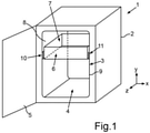
- a domestic refrigerator 1 is shown.
- the household refrigeration appliance 1 is designed for storing and preserving food.
- the household refrigeration appliance 1 can be a refrigerator or a freezer or a fridge-freezer combination appliance.
- the domestic refrigeration appliance 1 has a housing 2 .
- An inner container 3 is arranged in the housing 2 .
- the inner container 3 is preferably made of plastic.
- the inner container 3 delimits a receiving space 4 for food with walls.
- the receiving space 4 of the household refrigeration appliance 1 can be closed by a door 5 which is movably arranged on the housing 2 .
- the household refrigeration appliance 1 has at least one food storage container or food storage tray 6 .
- This can be pushed into the receiving space 4 and pulled out.
- the food receiving tray 6 has a receiving volume 7 into which food or stored goods can be placed.
- the inner container 3 has vertical side walls 8 and 9 .
- Guide devices 10 and 11, each with partial components, are formed on these side walls 8 and 9.
- the food receiving tray 6 can be displaced in the depth direction (z-direction) of the household refrigeration appliance 1 with these guide devices 10 and 11 .
- the guide device 11 on the right here has a guide rail 12 .
- This guide rail 12 is arranged on the side wall 9 .
- the guide rail 12 has a base part 13 .
- an asymmetric component 14 can be provided in one exemplary embodiment.
- the asymmetric component 14 is preferably a part separate from the base part 13 .
- the asymmetric component 14 is designed in one piece. It is connected to the base part 13 in a stationary manner. In particular, a non-destructively releasable connection is provided here. This makes it possible for this asymmetric component 14 to be designed as an interchangeable component.
- it can be connected there to an embodiment of a base part 15 that is preferably present and fastened to it in a stationary manner.
- This one asymmetric component 14 achieves an asymmetric geometry in the width direction (x-direction) of the household refrigeration appliance 1 when viewed in this regard.
- the guide device 11, in particular the guide rail 12, in particular the asymmetric component 14, has an integrated guide groove 16.
- This guide groove 16 is open at the bottom in the height direction (y-direction) of the household refrigeration appliance 1 .
- the guiding device 11 also has at least one guiding element 17 .
- the guide element 17 is formed on the receiving tray 6 .
- this at least one guide element 17 is produced in one piece with the food receiving tray 6 .
- this guide element 17 is arranged on a side wall 18 of this food receiving tray 6, in particular formed on an outer side 18a.
- this guide element 17 is also arranged on a bottom wall 19 of the food receiving tray 6 . In particular, it is formed on an outer side 19a of this bottom wall 19.
- this guide element 17 also extends in the width direction laterally next to the side wall 18 and further down than the bottom wall 19. In a front view, as shown in FIG 2 is shown, this guide element 17 thus has an L-like shape.
- this guide element 17 has a guide bar 20 protruding upwards. This is designed to engage in the guide groove 16 from below. This is how this is in 3 shown, an interlocking state is realized. In 3 is an enlarged view of the section in this regard I in 2 shown.
- This interlocking of the guide bar 20 with the guide groove 16 results in a rollerless fixed bearing 21.
- a width b1 of the guide groove 16 is dimensioned such that it is between 0.1 mm and 0.6 mm greater than a width b2 of the guide bar 20.
- the guide element 17 has an integrated sliding element 23.
- This sliding element 22 has a sliding surface 23 . In particular, this sliding surface 23 is a curved sliding surface.
- the guide element 17 rests on a support 24 with this sliding surface 23 .
- the support 24 is part of the guide rail 12, in particular of the base part 13.
- the one-piece design of the guide element 17 with the food receiving tray 6 also enables sliding on this support 24 in this regard sliding motion.
- At least one guide element 28 is formed not only on this one side 25 of the food receiving tray 6 but also on the opposite side 26, and there on another vertical side wall 27 as well.
- This guide element 28 is designed in accordance with the guide element 17 . Since only this base part 13 of the guide device 10 is present on this side on the left in the exemplary embodiment and no such asymmetric component 14 , the guide of the guide element 28 is provided there only on the base part 15 . As a result, a loose bearing 29 is formed.
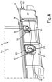
- the food receiving tray 6 and the guide device 11 are shown in a perspective partial illustration.
- the relevant guide rail 12 is shown transparent so that the guide element 17 can be seen.
- a further guide element 30 is integrally formed on this side wall 18 in this context. Viewed in the depth direction, this further guide element 30 is arranged further to the rear than the guide element 17 which is spaced apart therefrom and offset to the front.
- This further guide element 30 is also formed with a guide web 32 which is oriented upwards. In the coupled state, an interlocking with the guide groove 16 is also formed here.
- this guide element 30 is also designed with an integrated anti-tilt element 33. As a result, a food receiving tray 6 that has been pulled out relatively far can be prevented from tipping down.
- the sliding element 23 is designed as a ring.
- the guide bar 20 protrudes radially upwards from this.
- At least one guide element 17, which is formed on one side of the food receiving tray 6, is arranged laterally next to this side wall 18 in the width direction of the household refrigeration appliance 1 and overlaps with the side wall 18 in the height direction of the household refrigeration appliance and is located under a bottom wall 19 in the height direction and in the width direction arranged to extend the food receiving tray.
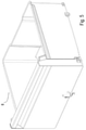
- Figure 6 shows a perspective view of the food receiving tray 6.
Landscapes
- Engineering & Computer Science (AREA)
- Chemical & Material Sciences (AREA)
- Combustion & Propulsion (AREA)
- Physics & Mathematics (AREA)
- Mechanical Engineering (AREA)
- Thermal Sciences (AREA)
- General Engineering & Computer Science (AREA)
- Devices That Are Associated With Refrigeration Equipment (AREA)
- Devices For Warming Or Keeping Food Or Tableware Hot (AREA)
Abstract
Description
- Ein Aspekt der Erfindung betrifft ein Haushaltskältegerät mit einem Innenbehälter. Der Innenbehälter begrenzt einen Aufnahmeraum zur Aufnahme von Lebensmitteln. Das Haushaltskältegerät weist darüber hinaus eine zu dem Aufnahmeraum separate Lebensmittel-Aufnahmeschale auf. Des Weiteren weist das Haushaltskältegerät eine Führungsvorrichtung auf, mit welcher die Lebensmittel-Aufnahmeschale bewegungsführbar ist. Die Führungsvorrichtung weist eine Führungsschiene auf, die ortsfest an einer Innenseite des Innenbehälters angeordnet ist.
- Bei Haushaltskältegeräten ist es üblich, dass derartige Lebensmittel-Aufnahmeschalen in dem Innenraum angeordnet sind. Sie können in Tiefenrichtung des Haushaltskältegeräts herausgezogen und eingeschoben werden. Dazu sind unterschiedlichste und vielfältigste Lagerungen und Führungsvorrichtungen bekannt.
- Üblich ist es in dem Zusammenhang, dass Rollen an der Schale angeordnet sind, sodass diesbezüglich eine Rollenführung vorgesehen ist. Derartige Rollen können jedoch auch in der Führungsschiene des Innenbehälters angeordnet sein.
- Es ist Aufgabe der vorliegenden Erfindung, ein Haushaltskältegerät zu schaffen, bei welchem die Bewegungsführung einer derartigen Lebensmittel-Aufnahmeschale verbessert ist.
- Diese Aufgabe wird durch ein Haushaltskältegerät, welches die Merkmale nach Anspruch 1 aufweist, gelöst.
- Ein Aspekt der Erfindung betrifft ein Haushaltskältegerät mit einem Innenbehälter. Dieser Innenbehälter begrenzt mit Wänden einen Aufnahmeraum des Haushaltskältegeräts, welcher zur Aufnahme von Lebensmitteln ausgebildet ist. Das Haushaltskältegerät weist eine zu dem Aufnahmeraum separate Lebensmittel-Aufnahmeschale auf. Darüber hinaus weist das Haushaltskältegerät eine Führungsvorrichtung auf, mit welcher die Lebensmittel-Aufnahmeschale bewegungsführbar ist. Die Führungsvorrichtung weist eine Führungsschiene auf. Die Führungsschiene ist ortsfest an einer Innenseite des Innenbehälters angeordnet. Die Führungsvorrichtung weist darüber hinaus zumindest ein zur Führungsschiene separates Führungselement auf, welches an der Lebensmittel-Aufnahmeschale ortsfest angeordnet ist. Die Führungsschiene ist mit diesem Führungselement ineinandergreifend angeordnet, sodass ein rollenloses Festlager dadurch gebildet ist. Dadurch ist die Lebensmittel-Aufnahmeschale rollenlos mit der Führungsvorrichtung führbar. Denn durch eine derartige Ausgestaltung ist einerseits eine mechanisch einfache und dennoch für die Führung vorteilhafte nutzerfreundliche Führungsvorrichtung geschaffen. Durch eine derartige rollenlose Ausgestaltung, was bedeutet, dass die Führungsvorrichtung insbesondere weder schalenseitig noch innenbehälterseitig Rollen aufweist, können die eingangs genannten Nachteile behoben werden. Insbesondere ist es durch eine derartige Führungsvorrichtung mit einem diesbezüglich rollenlosen Festlager ermöglicht, dass bei dem Herausziehen oder Hineinschieben der Lebensmittel-Aufnahmeschale unerwünschte Seitenbewegungen beziehungsweise Versatzbewegungen in Breitenrichtung des Haushaltskältegeräts auftreten. Die sehr lineare Bewegungsführung der Schale in Tiefenrichtung ist dadurch ermöglicht.
- In einem Ausführungsbeispiel ist vorgesehen, dass das Führungselement einstückig mit der Lebensmittel-Aufnahmeschale hergestellt ist. Dadurch kann die Bauteilzahl reduziert werden. Insbesondere können somit auch Montagetoleranzen und Bewegungstoleranzen vermieden werden. Vorzugsweise ist es dadurch auch erreicht, dass die Position zwischen dem Führungselement und der Lebensmittel-Aufnahmeschale dauerhaft konstant bleibt. Dies ist vorteilhaft für die mechanische Kopplung mit der Führungsschiene und die diesbezüglich spielminimierte Lagerung der Schale an der Führungsvorrichtung, sodass diesbezüglich Seitwärtsbewegungen beim Herausziehen und Hineinschieben zumindest deutlich reduziert werden können.
- Dieses zumindest eine Führungselement an der Lebensmittel-Aufnahmeschale ist positionsstarr daran angeordnet. Dies bedeutet, dass die diesbezügliche Ausgestaltung keine Relativbewegung des Führungselements zur Schale zulässt. Eine derartige unbewegliche Anordnung des Führungselements an der Schale begünstigt die oben genannten Vorteile.
- Insbesondere ist dies durch die genannte einstückige Ausgestaltung und Herstellung ermöglicht.
- In einem Ausführungsbeispiel ist das Führungselement an einer Außenseite einer Seitenwand der Lebensmittel-Aufnahmeschale und an einer Außenseite der Bodenwand der Lebensmittel-Aufnahmeschale ausgebildet. Dieses Führungselement ist somit in zumindest zwei Raumrichtungen exponiert über die Ausmaße derjenigen Wände der Lebensmittel-Aufnahmeschale ausgebildet, die den Aufnahmevolumenbereich dieser Lebensmittel-Aufnahmeschale begrenzen. Ein derartiges seitliches und nach unten erhabenes Überstehen des Führungselements ermöglicht einerseits eine einfache und zielsichere Kopplung mit der Führungsnut, andererseits zusätzlich auch ein weiteres Auflegen der Lebensmittel-Aufnahmeschale mit dem Führungselement von oben auf eine weitere Auflage, die am Innenbehälter angeordnet ist. Ein besonders vorteilhaftes Lagerungs- und Führungskonzept ist dadurch ermöglicht. Eine derartige Ausgestaltung ist auch besonders vorteilhaft im Vergleich zu Konzepten, die lediglich ein nach unten und kein seitliches in Breitenrichtung erfolgendes Überstehen der Führungsvorrichtung aufweisen. Denn wie bereits erwähnt, ist dadurch gemäß dem oben genannten vorteilhaften Ausführungsbeispiel das Koppeln und Führen einfacher und präziser.
- In einem Ausführungsbeispiel ist das zumindest eine Führungselement nur an einer Seite der Lebensmittel-Aufnahmeschale ausgebildet. Dies bezieht sich insbesondere auf eine Betrachtung in Breitenrichtung. Beispielsweise ist somit das zumindest eine Führungselement bei einer frontseitigen Betrachtung des Haushaltskältegeräts rechtsseitig ausgebildet. Linksseitig ist dann diesbezüglich kein derartiges Führungselement vorgesehen. Bei einer derartigen Ausgestaltung ist die Lebensmittel-Aufnahmeschale dahingehend zu verwenden, dass sie bei frontseitiger Betrachtung an einer rechtsseitig an einer vertikalen Seitenwand des Innenbehälters angeordneten Führungsvorrichtung beziehungsweise der diesbezüglichen Führungsschiene, koppelbar ist. Eine linksseitige Kopplung ist dann nicht vorgesehen.
- In einem vorteilhaften Ausführungsbeispiel ist jeweils zumindest ein Führungselement an einer in Breitenrichtung betrachteten jeweiligen gegenüberliegen Seite der Lebensmittel-Aufnahmeschale ausgebildet. Insbesondere ist diesbezüglich eine symmetrische Ausgestaltung ausgebildet. Dadurch kann eine derartige Lebensmittel-Aufnahmeschale sowohl an einer bei frontseitiger Betrachtung rechtsseitig an einer vertikalen Seitenwand des Innenbehälters angeordneten Führungsschiene einer Führungsvorrichtung führend gekoppelt werden. Ebenso kann in einer alternativen Ausführung die gleiche Lebensmittel-Aufnahmeschale jedoch an einer linksseitig angeordneten Führungsschiene am Innenbehälter gekoppelt werden und bewegungsgeführt werden.
- Dadurch kann auch bei einem diesbezüglichen Anschlagwechsel nur mit einem Vertauschen der Führungsschiene, insbesondere eines separaten Asymmetriebauteils der Führungsschiene, der Führungsvorrichtung die gleiche Lebensmittel-Aufnahmeschale genutzt werden und entsprechend verbessert geführt werden. In dem Zusammenhang kann eine Führungsschiene, insbesondere das Asymmetriebauteil als Wechselkomponente, einer Führungsvorrichtung vorzugsweise an einer rechtsseitigen vertikalen Seitenwand des Innenbehälters oder an einer linksseitigen vertikalen Seitenwand des Innenbehälters angeordnet sein.
- Vorzugsweise weist die Führungsschiene ein Basisteil auf, welches an der Seitenwand des Innenbehälters angeordnet ist. Dieses Basisteil kann einstückig mit der Seitenwand ausgebildet sein. Das Basisteil kann in einer alternativen Ausführung jedoch auch als separates Bauteil ausgebildet sein und an dem Innenbehälter, insbesondere dieser vertikalen Seitenwand, befestigt sein. Es kann vorgesehen sein, dass die Führungsschiene, insbesondere zusätzlich zu einem derartigen Basisteil, ein Asymmetriebauteil aufweist. Mit diesem Asymmetriebauteil ist in Breitenrichtung der Lebensmittel-Aufnahmeschale betrachtet eine Asymmetriegeometrie für die Lagerung der Lebensmittel-Aufnahmeschale ausgebildet. Dieses Asymmetriebauteil, welches insbesondere schienenartig gebildet ist, ist somit in Breitenrichtung betrachtet nur an einer Seite in Bezug zur Lebensmittel-Aufnahmeschale angeordnet. Insbesondere ist dieses Asymmetriebauteil ortsfest an dem Innenbehälter angeordnet. Dies bedeutet, dass dieses Asymmetriebauteil bei einer Bewegung der Lebensmittel-Aufnahmeschale in Tiefenrichtung nicht mit der Schale mitbewegt wird.
- Es kann vorgesehen sein, dass dieses Asymmetriebauteil ein zum Basisteil separates Bauteil ist. Das Asymmetriebauteil kann ortsfest an dem Basisteil befestigt sein.
- In einem Ausführungsbeispiel ist vorgesehen, dass das Führungselement einen nach oben ragenden Führungssteg aufweist. Die Führungsschiene weist in einem vorteilhaften Ausführungsbeispiel eine nach unten offene Führungsnut auf. Insbesondere greift im gekoppelten Zustand dieser Führungssteg von unten in dieselbe Führungsnut ein. Die Führungsnut ist in Breitenrichtung betrachtet durch eine jeweilige Begrenzungswand begrenzt. Im Querschnitt ist die Führungsnut diesbezüglich beidseits begrenzt. Damit kann in besonders vorteilhafter Weise eine unerwünschte Bewegung in Breitenrichtung dieser Lebensmittel-Aufnahmeschale vermieden werden, wenn diese in Tiefenrichtung bewegt wird. Hierdurch ist ein sehr einfaches und hochwirksames Kopplungs- und Führungsprinzip durch diese Ausgestaltung erreicht.
- In einem Ausführungsbeispiel ist vorgesehen, dass die Führungsnut eine in Breitenrichtung des Haushaltskältegeräts bemessene Breite aufweist, die zwischen 0,1 mm und 0,6 mm größer als die in dieser Breitenrichtung bemessene Breite des Führungsstegs ist. Dies ist eine weitere vorteilhafte Ausführung im Hinblick auf die Reduzierung oder Vermeidung von Seitwärtsbewegungen der Schale beim Bewegen in Tiefenrichtung.
- Insbesondere ist vorgesehen, dass der Führungssteg und die Führungsnut in Breitenrichtung des Haushaltskältegeräts betrachtet seitlich neben einer Seitenwand der Lebensmittel-Aufnahmeschale angeordnet sind. Insbesondere ist vorgesehen, dass der Führungssteg und die Führungsnut in Höhenrichtung des Haushaltskältegeräts betrachte überlappend mit dieser Seitenwand der Lebensmittel-Aufnahmeschale angeordnet sind. Diese spezifische Positionierung des Führungsstegs und der Führungsnut ermöglichen auch, dass die Schale als solche bezüglich eines Aufnahmevolumens nicht reduziert werden muss. Darüber hinaus ist durch diese exponierte Position des Führungsstegs und der Führungsnut ein sehr einfaches Koppeln ermöglicht. Andererseits ist dadurch auch eine besonders präzise Führung ermöglicht. Die eingangs erwähnte Vorteilhaftigkeit bezüglich der zumindest Reduzierung der Versatzbewegung in Breitenrichtung wird dadurch besonders begünstigt.
- In einem Ausführungsbeispiel ist vorgesehen, dass zwei separate Führungselemente mit jeweils einem Führungssteg ausgebildet sind. Diese separaten Führungsstege greifen in dieselbe Führungsnut ein. Dadurch wird das Lagerungs- und Führungskonzept nochmals verbessert und stabilisiert. Gerade die unerwünschten Seitwärtsbewegungen beim Herausziehen oder Hineinschieben der Lebensmittel-Aufnahmeschale aus dem Aufnahmeraum heraus beziehungsweise in den Aufnahmeraum hinein können dadurch verbessert vermieden werden.
- In einem Ausführungsbeispiel ist vorgesehen, dass diese Führungsstege in einer in Tiefenrichtung bemessenen hinteren Längenhälfte der Lebensmittel-Aufnahmeschale angeordnet sind. Dadurch lässt auch ein entsprechendes Führungskonzept erreichen, wenn die Lebensmittel-Aufnahmeschale bereits relativ weit aus dem Aufnahmeraum herausgezogen ist.
- In einem Ausführungsbeispiel ist vorgesehen, dass ein Führungselement ein Gleitelement aufweist. Insbesondere ist dieses Gleitelement mit einer gekrümmten Gleitfläche ausgebildet. Dadurch soll eine Kontaktfläche geschaffen werden, die ähnlich der ist, wie sie bei einer sich drehenden Rolle realisiert ist. Das Gleitverhalten ist dadurch vorteilhaft unterstützt. Dennoch ist es nicht erforderlich, eine diesbezüglich angeordnete und sich bewegende beziehungsweise drehende Rolle vorzusehen. Insbesondere liegt das Führungselement mit dieser Gleitfläche auf einer Auflage der Führungsschiene auf und wird beim Bewegen der Lebensmittel-Aufnahmeschale dadurch entlanggleitend geführt. Somit ist es auch ermöglicht, dass kein Element vorhanden ist, welches eine Relativbewegung zu derjenigen Komponente durchführt, an welcher es angeordnet ist, wie dies bei Rollen der Fall ist. Es wird hier somit kein Rollen sondern ein Gleiten durchgeführt.
- Dies begünstigt die Reduzierung der Seitenbewegungen, da nicht erforderlich ist, ein derartiges Führungselement relativbewegbar zu lagern und somit auch ein gewisses Lagerungskonzept mit Spiel vorzusehen. Dies ist jedoch im Vergleich dazu bei Rollen erforderlich.
- In einem Ausführungsbeispiel ist vorgesehen, dass das Führungselement, welches dieses Gleitelement aufweist, als Ring ausgebildet ist, an welchem der Führungssteg radial nach oben stehend absteht. Durch eine derartige Ausgestaltung kann einerseits ein sehr gewichtssparendes Führungselement geschaffen werden. Andererseits ist eine stabile Geometrie dieses Führungselements erreicht.
- In einem Ausführungsbeispiel ist ein Führungselement als Kippschutzelement ausgebildet. Mit diesem Kippschutzelement kann ein nach unten kippen der Lebensmittel-Aufnahmeschale im relativ weit ausgezogenen Zustand verhindert werden. Somit sind mehrere Führungselemente vorhanden, die zusätzlich zur Führung auch weitere Funktionen aufweisen.
- Insbesondere sind diesbezüglich an einer Seite der Lebensmittel-Aufnahmeschale zwei derartige separate Führungselemente ausgebildet. Das eine weist zusätzlich zu seiner-Führungsfunktion die Kippschutzfunktion auf. Das andere Führungselement weist zusätzlich zu seiner Führungsfunktion die Gleitfunktion auf. Dieses Element ist somit einerseits nach oben hin in die Führungsnut gekoppelt, andererseits nach unten hin auf der Auflagefläche aufliegend, um auf dieser zu gleiten. In Tiefenrichtung betrachtet ist das Führungselement, welches das Kippschutzelement integral aufweist weiter hinten an der Lebensmittel-Aufnahmeschale ausgebildet, als das andere Führungselement.
- Insbesondere ist dieses Führungselement, welches auch das Kippschutzelement aufweist, an einem hinteren Ende einer Seitenwand der Lebensmittel-Aufnahmeschale angeordnet. Insbesondere in einem hinteren Eckbereich ist die diesbezügliche Anordnung vorgesehen.
- In einem Ausführungsbeispiel ist zumindest ein Führungselement in Breitenrichtung des Haushaltskältegeräts betrachtet seitlich neben einer Seitenwand der Lebensmittel-Aufnahmeschale angeordnet beziehungsweise erstreckt sich seitlich zu dieser Seitenwand. Darüber hinaus erstreckt sich dieses Führungselement in Höhenrichtung des Haushaltskältegeräts betrachtet überlappend mit der Seitenwand der Lebensmittel-Aufnahmeschale. In Höhenrichtung und in Breitenrichtung betrachtet erstreckt sich dieses Führungselement insbesondere auch unter eine Bodenwand der Lebensmittel-Aufnahmeschale. Insbesondere erstreckt sich das Führungselement direkt von der Außenseite der Seitenwand seitlich weg und erstreckt sich direkt von der Außenseite der Bodenwand nach unten weg.
- In einem Ausführungsbeispiel ist das Führungselement an einer Seite der Lebensmittel-Aufnahmeschale ausgebildet und zumindest ein weiteres Führungselement der Führungsvorrichtung ist an einer gegenüberliegenden Seite der Lebensmittel-Aufnahmeschale ortsfest angeordnet. Eine weitere Führungsschiene ist an einer Innenseite des Innenbehälters, insbesondere an einer zur ersten Seitenwand, an welcher die Führungsschiene angeordnet ist, gegenüberliegenden zweiten Seitenwand, angeordnet und ist mit dem weiteren Führungselement gekoppelt, so dass dadurch ein rollenloses Loslager gebildet ist.
- Mit Angaben "oben", "unten", "vorne", "hinten, "horizontal", "vertikal", "Tiefenrichtung", "Breitenrichtung", "Höhenrichtung" etc. sind die bei bestimmungsgemäßen Gebrauch und bestimmungsgemäßem Anordnen des Geräts und bei einem dann vor dem Gerät stehenden und in Richtung des Geräts blickenden Beobachter gegebenen Positionen und Orientierungen angegeben.
- Weitere Merkmale der Erfindung ergeben sich aus den Ansprüchen, den Figuren und der Figurenbeschreibung. Die vorstehend in der Beschreibung genannten Merkmale und Merkmalskombinationen, sowie die nachfolgend in der Figurenbeschreibung genannten und/oder in den Figuren alleine gezeigten Merkmale und Merkmalskombinationen sind nicht nur in der jeweils angegebenen Kombination, sondern auch in anderen Kombinationen verwendbar, ohne den Rahmen der Erfindung zu verlassen. Es sind somit auch Ausführungen von der Erfindung als umfasst und offenbart anzusehen, die in den Figuren nicht explizit gezeigt und erläutert sind, jedoch durch separierte Merkmalskombinationen aus den erläuterten Ausführungen hervorgehen und erzeugbar sind. Es sind auch Ausführungen und Merkmalskombinationen als offenbart anzusehen, die somit nicht alle Merkmale eines ursprünglich formulierten unabhängigen Anspruchs aufweisen. Es sind darüber hinaus Ausführungen und Merkmalskombinationen, insbesondere durch die oben dargelegten Ausführungen, als offenbart anzusehen, die über die in den Rückbezügen der Ansprüche dargelegten Merkmalskombinationen hinausgehen oder abweichen.
- Ausführungsbeispiele der Erfindung werden nachfolgend anhand schematischer Zeichnungen näher erläutert. Es zeigen:
- Fig. 1
- eine schematische Darstellung eines Ausführungsbeispiels eines Haushaltskältegeräts;
- Fig. 2
- eine Frontansicht von Teilkomponenten des Haushaltskältegeräts gemäß
Fig. 1 , wobei eine Lebensmittel-Aufnahmeschale einer Führungsvorrichtung geführt ist; - Fig. 3
- eine vergrößerte Darstellung eines Teilbereichs in
Fig. 2 ; - Fig. 4
- eine perspektivische und teilweise transparente Darstellung der Ausgestaltung in
Fig. 3 , wobei inFig. 4 eine perspektivische Ansicht gezeigt ist; und - Fig. 5
- eine perspektivische Darstellung einer Lebensmittel-Aufnahmeschale.
- In den Figuren werden gleiche oder funktionsgleiche Elemente mit den gleichen Bezugszeichen versehen.
- In
Fig. 1 ist ein Haushaltskältegerät 1 gezeigt. Das Haushaltskältegerät 1 ist zum Lagern und Konservieren von Lebensmitteln ausgebildet. Das Haushaltskältegerät 1 kann ein Kühlgerät oder einer Gefriergerät oder ein Kühl-Gefrier-Kombigerät sein. Das Haushaltskältegerät 1 weist ein Gehäuse 2 auf. In dem Gehäuse 2 ist ein Innenbehälter 3 angeordnet. Der Innenbehälter 3 ist vorzugsweise aus Kunststoff ausgebildet. Der Innenbehälter 3 begrenzt mit Wänden einen Aufnahmeraum 4 für Lebensmittel. Der Aufnahmeraum 4 des Haushaltskältegeräts 1 ist durch eine Tür 5, welche bewegbar an dem Gehäuse 2 angeordnet ist, verschließbar. - Darüber hinaus weist das Haushaltskältegerät 1 zumindest einen Lebensmittel-Aufnahmebehälter beziehungsweise eine Lebensmittel-Aufnahmeschale 6 auf. Diese kann in den Aufnahmeraum 4 hineingeschoben und herausgezogen werden. Die Lebensmittel-Aufnahmeschale 6 weist ein Aufnahmevolumen 7 auf, in welches Lebensmittel beziehungsweise Lagergüter eingebracht werden können. Wie in
Fig. 1 zu erkennen ist, weist der Innenbehälter 3 vertikale Seitenwände 8 und 9 auf. An diesen Seitenwänden 8 und 9 sind Führungsvorrichtungen 10 und 11 mit jeweils Teilkomponenten ausgebildet. Mit diesen Führungsvorrichtungen 10 und 11 kann die Lebensmittel-Aufnahmeschale 6 in Tiefenrichtung (z-Richtung) des Haushaltskältegeräts 1 verschoben werden. - Dadurch ist die Lebensmittel-Aufnahmeschale 6 bewegungsführbar.
- In
Fig. 2 sind in einer Frontansicht die Lebensmittel-Aufnahmeschale 6 und die Führungsvorrichtungen 10 und 11 gezeigt. Wie zu erkennen ist, weist die hier rechtsseitige Führungsvorrichtung 11 eine Führungsschiene 12 auf. Diese Führungsschiene 12 ist an der Seitenwand 9 angeordnet. In einem Ausführungsbeispiel weist die Führungsschiene 12 ein Basisteil 13 auf. Zusätzlich zu dem Basisteil 13 kann in einem Ausführungsbeispiel ein Asymmetriebauteil 14 vorgesehen sein. Das Asymmetriebauteil 14 ist vorzugsweise ein zum Basisteil 13 separates Teil. Das Asymmetriebauteil 14 ist einstückig ausgebildet. Es ist ortsfest mit dem Basisteil 13 verbunden. Insbesondere ist hier eine zerstörungsfrei lösbare Verbindung vorgesehen. Dadurch ist es ermöglicht, dass dieses Asymmetriebauteil 14 als Wechselbauteil ausgebildet ist. Dies bedeutet, dass es auch getauscht werden kann und bei der linksseitigen Führungsvorrichtung 10 verbaut werden kann. Insbesondere kann es dort mit einer vorzugsweise vorhandenen Ausgestaltung eines Basisteils 15 verbunden werden und ortsfest daran befestigt werden. Durch dieses eine Asymmetriebauteil 14 wird bei der diesbezüglichen Betrachtung eine Asymmetriegeometrie in Breitenrichtung (x-Richtung) des Haushaltskältegeräts 1 erreicht. Wie zu erkennen ist, weist die Führungsvorrichtung 11, insbesondere die Führungsschiene 12, insbesondere das Asymmetriebauteil 14, eine integrierte Führungsnut 16 auf. Diese Führungsnut 16 ist in Höhenrichtung (y-Richtung) des Haushaltskältegeräts 1 nach unten hin offen. Die Führungsvorrichtung 11 weist insbesondere auch zumindest ein Führungselement 17 auf. Das Führungselement 17 ist an der Aufnahmeschale 6 ausgebildet. Insbesondere ist dieses zumindest eine Führungselement 17 einstückig mit der Lebensmittel-Aufnahmeschale 6 hergestellt. In einem Ausführungsbeispiel ist dieses Führungselement 17 an einer Seitenwand 18 dieser Lebensmittel-Aufnahmeschale 6 angeordnet, insbesondere an einer Außenseite 18a angeformt. Insbesondere ist dieses Führungselement 17 auch an einer Bodenwand 19 der Lebensmittel-Aufnahmeschale 6 angeordnet. Insbesondere ist es an einer Außenseite 19a dieser Bodenwand 19 angeformt. In einem Ausführungsbeispiel erstreckt sich somit dieses Führungselement 17 in Breitenrichtung auch seitlich neben der Seitenwand 18 und weiter nach unten als die Bodenwand 19. In einer Frontansicht, wie es inFig. 2 gezeigt ist, weist dieses Führungselement 17 somit eine L-artige Form auf. - Wie bereits in
Fig. 2 zu erkennen ist, weist dieses Führungselement 17 einen nach oben überstehenden Führungssteg 20 auf. Dieser ist zum Eingreifen von unten in die Führungsnut 16 ausgebildet. Dadurch ist, wie dies inFig. 3 gezeigt ist, ein ineinandergreifender Zustand realisiert. InFig. 3 ist diesbezüglich eine vergrößerte Darstellung des Ausschnitts I inFig. 2 dargestellt. Durch dieses Ineinandergreifen des Führungsstegs 20 mit der Führungsnut 16 ergibt sich ein rollenloses Festlagern 21. Insbesondere ist vorgesehen, dass sich eine Breite b1 der Führungsnut 16 derart bemisst, dass sie zwischen 0,1 mm und 0,6 mm größer ist, als eine Breite b2 des Führungsstegs 20. Darüber hinaus ist zu erkennen, dass das Führungselement 17 integriert ein Gleitelement 23 aufweist. Dieses Gleitelement 22 weist eine Gleitfläche 23 auf. Insbesondere ist diese Gleitfläche 23 eine gekrümmte Gleitfläche. Mit dieser Gleitfläche 23 liegt das Führungselement 17 an einer Auflage 24 auf. Die Auflage 24 ist Bestandteil der Führungsschiene 12, insbesondere des Basisteils 13. Die einstückige Ausgestaltung des Führungselements 17 mit der Lebensmittel-Aufnahmeschale 6 ermöglicht diesbezüglich auch ein Gleiten auf dieser Auflage 24. Die bewegungsfixierte Position des Führungselements 17 an der Lebensmittel-Aufnahmeschale 6 ermöglicht diese Gleitbewegung. - Wie darüber hinaus in
Fig. 2 auch zu erkennen ist, ist in einem vorteilhaften Ausführungsbeispiel nicht nur an dieser einen Seite 25 der Lebensmittel-Aufnahmeschale 6 sondern auch an der gegenüberliegenden Seite 26, und dort an einer weiteren vertikalen Seitenwand 27 ebenso zumindest ein Führungselement 28 ausgebildet. Dieses Führungselement 28 ist entsprechend dem Führungselement 17 gestaltet. Da auf dieser im Ausführungsbeispiel linken Seite nur dieses Basisteil 13 der Führungsvorrichtung 10 vorhanden ist und kein derartiges Asymmetriebauteil 14, ist die Führung des Führungselements 28 dort nur an dem Basisteil 15 vorgesehen. Dadurch ist ein Loslager 29 gebildet. - In
Fig. 4 ist in einer perspektivischen Teildarstellung die Lebensmittel-Aufnahmeschale 6 und die Führungsvorrichtung 11 gezeigt. Die diesbezügliche Führungsschiene 12 ist transparent dargestellt, sodass das Führungselement 17 zu erkennen ist. Im Ausführungsbeispiel ist in dem Zusammenhang ein weiteres Führungselement 30 an dieser Seitenwand 18 einstückig angeformt. Dieses weitere Führungselement 30 ist in Tiefenrichtung betrachtet weiter hinten angeordnet als das dazu beabstandet und nach vorne versetzte Führungselement 17. Es ist insbesondere an einem hinteren Eckbereich 31 der Lebensmittel-Aufnahmeschale 6 angeformt. Dieses weitere Führungselement 30 ist ebenfalls mit einem Führungssteg 32 ausgebildet, der nach oben orientiert ist. Im gekoppelten Zustand ist auch hier ein Ineinandergreifen mit der Führungsnut 16 ausgebildet. Darüber hinaus ist in einem vorteilhaften Ausführungsbeispiel dieses Führungselement 30 auch mit einem integrierten Kippschutzelement 33 gestaltet. Dadurch kann ein nach unten kippen einer relativ weit ausgezogenen Lebensmittel-Aufnahmeschale 6 verhindert werden. - Wie darüber hinaus gezeigt ist, ist in dem vorgesehenen Ausführungsbeispiel das Gleitelement 23 als Ring gestaltet. Von diesem ist der Führungssteg 20 radial nach oben abstehend. Zumindest ein Führungselement 17, welches auf einer Seite der Lebensmittel-Aufnahmeschale 6 ausgebildet ist, ist in Breitenrichtung des Haushaltskältegeräts 1 seitlich neben dieser Seitenwand 18 und in Höhenrichtung des Haushaltskältegeräts überlappend mit der Seitenwand 18 angeordnet und sich in Höhenrichtung und in Breitenrichtung unter eine Bodenwand 19 der Lebensmittel-Aufnahmeschale erstreckend angeordnet.
- Figur 6 zeigt eine perspektivische Darstellung der Lebensmittel-Aufnahmeschale 6.
-
- 1
- Haushaltskältegerät
- 2
- Gehäuse
- 3
- Innenbehälter
- 4
- Aufnahmeraum
- 5
- Tür
- 6
- Aufnahmeschale
- 7
- Aufnahmevolumen
- 8
- Seitenwände
- 9
- Seitenwände
- 10
- Führungsvorrichtung
- 11
- Führungsvorrichtung
- 12
- Führungsschiene
- 13
- Basisteil
- 14
- Asymmetriebauteil
- 15
- Basisteil
- 16
- Führungsnut
- 17
- Führungselement
- 18
- Seitenwand
- 18a
- Außenseite
- 19
- Bodenwand
- 19a
- Außenseite
- 20
- Führungssteg
- 21
- Festlager
- 22
- Gleitelement
- 23
- Gleitelement
- 24
- Auflage
- 25
- Seite
- 26
- Seite
- 27
- Seitenwand
- 28
- Führungselement
- 29
- Loslager
- 30
- Führungselement
- 31
- Eckbereich
- 32
- Führungssteg
- 33
- Kippschutzelement
- b1
- Breite
- b2
- Breite
Claims (15)
- Haushaltskältegerät (1) mit einem Innenbehälter (3), der einen Aufnahmeraum (4) zur Aufnahme von Lebensmitteln begrenzt, mit einer dazu separaten Lebensmittel-Aufnahmeschale (6) und mit einer Führungsvorrichtung (10, 11), mit welcher die Lebensmittel-Aufnahmeschale (6) bewegungsführbar ist, wobei die Führungsvorrichtung (10, 11) eine Führungsschiene (12) aufweist, die an einer Innenseite des Innenbehälters (3) angeordnet ist, dadurch gekennzeichnet, dass zumindest ein Führungselement (17, 30) der Führungsvorrichtung (10, 11) an der Lebensmittel-Aufnahmeschale (6) ortsfest angeordnet ist, wobei die Führungsschiene (12) mit dem Führungselement (17, 30) ineinandergreifend angeordnet ist, so dass ein rollenloses Festlager (21) gebildet ist, so dass die Lebensmittel-Aufnahmeschale (6) rollenlos mit der Führungsvorrichtung (10, 11) geführt ist.
- Haushaltskältegerät (1) nach Anspruch 1, dadurch gekennzeichnet, dass ein Führungselement (17, 28, 30) einstückig mit der Lebensmittel-Aufnahmeschale (6) hergestellt ist.
- Haushaltskältegerät (1) nach Anspruch 1 oder 2, dadurch gekennzeichnet, dass ein Führungselement (17, 28, 30) an einer Außenseite (18a) einer Seitenwand (18, 27) der Lebensmittel-Aufnahmeschale (6) und an einer Außenseite (19a) einer Bodenwand (19) der Lebensmittel-Aufnahmeschale (6) ausgebildet ist, insbesondere sich zumindest ein Führungselement (17, 28, 30) in Breitenrichtung (x) des Haushaltskältegeräts (1) seitlich neben einer Seitenwand (18, 27) der Lebensmittel-Aufnahmeschale (6) angeordnet ist und in Höhenrichtung (y) des Haushaltskältegeräts (1) überlappend mit der Seitenwand (18, 27) der Lebensmittel-Aufnahmeschale (6) angeordnet ist und sich in Höhenrichtung (y) und in Breitenrichtung (x) unter eine Bodenwand (19) des Lebensmittel-Aufnahmeschale (6) erstreckt.
- Haushaltskältegerät (1) nach einem der vorhergehenden Ansprüche, dadurch gekennzeichnet, dass zumindest ein Führungselement (17, 30) an einer ersten Seitenwand (18) der Lebensmittel-Aufnahmeschale (6) ausgebildet ist und zumindest ein weiteres Führungselement (28) an einer in Breitenrichtung (x) gegenüberliegenden zweiten Seitenwand (27) der Lebensmittel-Aufnahmeschale (6) ausgebildet ist.
- Haushaltskältegerät (1) nach einem der vorhergehenden Ansprüche, dadurch gekennzeichnet, dass die Führungsschiene (12) ein Asymmetriebauteil (14) aufweist, mit welchem in Breitenrichtung (x) des Lebensmittel-Aufnahmeschale (6) betrachtet eine Asymmetriegeometrie für die Lagerung der Lebensmittel-Aufnahmeschale (6) ausgebildet ist.
- Haushaltskältegerät (1) nach einem der vorhergehenden Ansprüche, dadurch gekennzeichnet, dass das Führungselement (17, 28, 30) einen nach oben ragenden Führungssteg (20, 32) aufweist, der in eine nach unten offene Führungsnut (16) in der Führungsschiene (12) eingreift.
- Haushaltskältegerät (1) nach Anspruch 6, dadurch gekennzeichnet, dass die Führungsnut (16) eine in Breitenrichtung (x) des Haushaltskältegeräts (1) bemessene Breite (b1) aufweist, die zwischen 0,1 mm und 0,6 mm größer als die Breite (b2) des Führungsstegs () ist.
- Haushaltskältegerät (1) nach Anspruch 6 oder 7, dadurch gekennzeichnet, dass der Führungssteg (20, 32) und die Führungsnut (16) in Breitenrichtung (x) des Haushaltskältegeräts (1) seitlich neben einer Seitenwand (18, 27) der Lebensmittel-Aufnahmeschale (6) angeordnet sind und/oder der Führungssteg (20, 32) und die Führungsnut (16) in Höhenrichtung (y) des Haushaltskältegeräts (1) überlappend mit der Seitenwand (18, 27) der Lebensmittel-Aufnahmeschale (6) angeordnet sind.
- Haushaltskältegerät (1) nach einem der vorhergehenden Ansprüche 6 bis 8, dadurch gekennzeichnet, dass zwei separate Führungselemente (17, 28, 30) mit jeweils einem Führungssteg (20, 32) ausgebildet sind, die in die Führungsnut (16) eingreifen.
- Haushaltskältegerät (1) nach Anspruch 9, dadurch gekennzeichnet, dass die Führungsstege (20, 32) in einer hinteren Längenhälfte der Lebensmittel-Aufnahmeschale (6) angeordnet sind.
- Haushaltskältegerät (1) nach einem der vorhergehenden Ansprüche, dadurch gekennzeichnet, dass ein Führungselement (17, 28, 30) ein Gleitelement (23) mit einer gekrümmten Gleitfläche (24) aufweist, mit welcher das Führungselement (17, 28, 30) auf einer Auflage (24) der Führungsschiene (12) aufliegt und beim Bewegen der Lebensmittel-Aufnahmeschale (6) gleitet.
- Haushaltskältegerät (1) nach Anspruch 11, dadurch gekennzeichnet, dass dieses Führungselement (17, 28, 30) als Ring ausgebildet ist, an welchem der Führungssteg (20, 32) radial nach oben absteht.
- Haushaltskältegerät (1) nach einem der vorhergehenden Ansprüche, dadurch gekennzeichnet, dass ein Führungselement (32) als Kippschutzelement (33) ausgebildet ist, mit welchem ein Nachuntenkippen der Lebensmittel-Aufnahmeschale (6) im ausgezogenen Zustand verhindert ist.
- Haushaltskältegerät (1) nach Anspruch 13, dadurch gekennzeichnet, dass dieses Führungselement (17, 28, 30) an einem hinteren Ende (31) einer Seitenwand (18, 27) der Lebensmittel-Aufnahmeschale (6) angeordnet ist.
- Haushaltskältegerät (1) nach einem der vorhergehenden Ansprüche, dadurch gekennzeichnet, dass das Führungselement (17, 30) an einer Seite (25) der Lebensmittel-Aufnahmeschale (6) ausgebildet ist und zumindest ein weiteres Führungselement (28) der Führungsvorrichtung (10, 11) an einer gegenüberliegenden Seite (26) der Lebensmittel-Aufnahmeschale (6) ortsfest angeordnet ist, wobei eine weitere Führungsschiene an einer Innenseite des Innenbehälters (3) angeordnet ist und mit dem weiteren Führungselement (28) gekoppelt ist, so dass dadurch ein rollenloses Loslager (29) gebildet ist.
Applications Claiming Priority (1)
| Application Number | Priority Date | Filing Date | Title |
|---|---|---|---|
| DE102020210279.1A DE102020210279A1 (de) | 2020-08-13 | 2020-08-13 | Haushaltskältegerät mit einer mit einem rollenlosen Festlager gelagerten Lebensmittel-Aufnahmeschale |
Publications (2)
| Publication Number | Publication Date |
|---|---|
| EP3954958A1 true EP3954958A1 (de) | 2022-02-16 |
| EP3954958B1 EP3954958B1 (de) | 2024-01-03 |
Family
ID=77042809
Family Applications (1)
| Application Number | Title | Priority Date | Filing Date |
|---|---|---|---|
| EP21187384.9A Active EP3954958B1 (de) | 2020-08-13 | 2021-07-23 | Haushaltskältegerät mit einer mit einem rollenlosen festlager gelagerten lebensmittel-aufnahmeschale |
Country Status (5)
| Country | Link |
|---|---|
| US (1) | US20220049894A1 (de) |
| EP (1) | EP3954958B1 (de) |
| CN (1) | CN114076488B (de) |
| DE (1) | DE102020210279A1 (de) |
| PL (1) | PL3954958T3 (de) |
Cited By (1)
| Publication number | Priority date | Publication date | Assignee | Title |
|---|---|---|---|---|
| EP4283227B1 (de) * | 2022-05-24 | 2025-12-03 | BSH Hausgeräte GmbH | Haushaltskältegerät mit einem lebensmittelbehälter mit einer stabilisierten kipp- und auszugsschutzvorrichtung |
Citations (4)
| Publication number | Priority date | Publication date | Assignee | Title |
|---|---|---|---|---|
| KR20000013051U (ko) * | 1998-12-23 | 2000-07-15 | 전주범 | 냉장고 선반의 유동방지구조 |
| DE102013203723A1 (de) * | 2013-03-05 | 2014-09-11 | BSH Bosch und Siemens Hausgeräte GmbH | Kältegerät mit einem versetzbaren Aufbewahrungsbehälter |
| WO2016023189A1 (zh) * | 2014-08-13 | 2016-02-18 | 简利宸 | 抽屉滑轨结构 |
| WO2017042228A1 (en) * | 2015-09-07 | 2017-03-16 | Ikea Supply Ag | A drawer, and a drawer sliding system for such drawer |
Family Cites Families (10)
| Publication number | Priority date | Publication date | Assignee | Title |
|---|---|---|---|---|
| JP2004353941A (ja) | 2003-05-28 | 2004-12-16 | Toshiba Corp | 冷蔵庫 |
| US8220285B2 (en) * | 2006-10-24 | 2012-07-17 | Lg Electronics Inc. | Refrigerator |
| KR20090106935A (ko) | 2008-04-07 | 2009-10-12 | 엘지전자 주식회사 | 드로어커버를 구비한 냉장고 |
| CN202853247U (zh) * | 2012-08-08 | 2013-04-03 | 海信(北京)电器有限公司 | 冰箱抽屉滑动组件及冰箱 |
| KR102028022B1 (ko) | 2013-04-05 | 2019-10-04 | 삼성전자주식회사 | 냉장고 |
| JP6392974B2 (ja) * | 2014-08-13 | 2018-09-19 | 簡利宸 | 引き出しの配置が自在な物入れ |
| CN205227987U (zh) | 2015-11-27 | 2016-05-11 | Tcl家用电器(合肥)有限公司 | 冰箱抽屉的滑槽结构及冰箱 |
| DE102018100724B4 (de) * | 2018-01-15 | 2023-03-30 | TANOS GmbH Verpacken *Ordnen* Präsentieren | Regalsystem für insbesondere Servicefahrzeuge und zugehöriger Container |
| CN208042604U (zh) | 2018-01-22 | 2018-11-02 | 青岛海尔股份有限公司 | 抽屉组件及具有抽屉组件的冰箱 |
| JP7127816B2 (ja) * | 2018-08-27 | 2022-08-30 | アクア株式会社 | 冷蔵庫 |
-
2020
- 2020-08-13 DE DE102020210279.1A patent/DE102020210279A1/de not_active Withdrawn
-
2021
- 2021-07-23 EP EP21187384.9A patent/EP3954958B1/de active Active
- 2021-07-23 PL PL21187384.9T patent/PL3954958T3/pl unknown
- 2021-08-11 CN CN202110917315.2A patent/CN114076488B/zh active Active
- 2021-08-11 US US17/399,483 patent/US20220049894A1/en not_active Abandoned
Patent Citations (4)
| Publication number | Priority date | Publication date | Assignee | Title |
|---|---|---|---|---|
| KR20000013051U (ko) * | 1998-12-23 | 2000-07-15 | 전주범 | 냉장고 선반의 유동방지구조 |
| DE102013203723A1 (de) * | 2013-03-05 | 2014-09-11 | BSH Bosch und Siemens Hausgeräte GmbH | Kältegerät mit einem versetzbaren Aufbewahrungsbehälter |
| WO2016023189A1 (zh) * | 2014-08-13 | 2016-02-18 | 简利宸 | 抽屉滑轨结构 |
| WO2017042228A1 (en) * | 2015-09-07 | 2017-03-16 | Ikea Supply Ag | A drawer, and a drawer sliding system for such drawer |
Cited By (1)
| Publication number | Priority date | Publication date | Assignee | Title |
|---|---|---|---|---|
| EP4283227B1 (de) * | 2022-05-24 | 2025-12-03 | BSH Hausgeräte GmbH | Haushaltskältegerät mit einem lebensmittelbehälter mit einer stabilisierten kipp- und auszugsschutzvorrichtung |
Also Published As
| Publication number | Publication date |
|---|---|
| DE102020210279A1 (de) | 2022-02-17 |
| PL3954958T3 (pl) | 2024-04-29 |
| CN114076488A (zh) | 2022-02-22 |
| US20220049894A1 (en) | 2022-02-17 |
| CN114076488B (zh) | 2024-05-14 |
| EP3954958B1 (de) | 2024-01-03 |
Similar Documents
| Publication | Publication Date | Title |
|---|---|---|
| EP3014202B1 (de) | Haushaltskältegerät mit einem frischhaltebehälter und einem bedienelement, das als push-push-verriegelungsmechanik zum bewegen eines deckels für den frischhaltebehälter ausgebildet ist | |
| DE102011053840A1 (de) | Einzugsvorrichtung zum Einbau in eine Auszugsführung | |
| EP1964490B1 (de) | Eckschrank, insbesondere Kücheneckschrank | |
| EP0685695A1 (de) | Kühlschrank mit Kühlgutablage | |
| EP3030853A1 (de) | Haushaltskältegerät mit einem innenbehälter und darin angeordneten entnehmbaren führungsschienen für eine schale | |
| EP3199896B1 (de) | Kühlschranktablar mit federelement | |
| EP0534107B1 (de) | Kühlgerät, insbesondere Kühl- oder Gefrierschrank | |
| EP3954958B1 (de) | Haushaltskältegerät mit einer mit einem rollenlosen festlager gelagerten lebensmittel-aufnahmeschale | |
| EP0718572A1 (de) | Möbel, insbesondere Haushaltsmöbel | |
| AT520691B1 (de) | Führungssystem | |
| EP2606296B1 (de) | Kältegerät mit einer tragschiene für einen fachboden | |
| EP0718571A1 (de) | Möbel, insbesondere Haushaltsmöbel | |
| DE102021207031A1 (de) | Ablageplattenanordnung zum Einbau in ein Haushaltskältegerät und Haushaltskältegerät | |
| EP2270407B1 (de) | Haushaltsgerät, insbesondere Kühl-und/oder Gefriergerät | |
| EP3077743B1 (de) | Haushaltskältegerät mit einem im innenraum verschiebbar angeordneten trägerschlitten | |
| EP0718573A1 (de) | Möbel, insbesondere Haushaltsmöbel | |
| DE4432821A1 (de) | Ausziehführung | |
| DE102009028434A1 (de) | Einbaubehälter für ein Kältegerät | |
| DE102017113937A1 (de) | Bockrolle und Möbel oder Haushaltsgerät mit einer derartigen Bockrolle | |
| DE102009045364A1 (de) | Innenbehälter für ein Kältegerät | |
| EP3954957A1 (de) | Lebensmittel-aufnahmeschale mit nach hinten verjüngter führungsschiene, sowie führungsvorrichtung und haushaltskältegerät | |
| DE102016219885A1 (de) | Haushaltskältegerät mit einer Mitnehmerschräge an einem Lagerteil für eine Schale auf einer Auszugsvorrichtung | |
| EP0611932A1 (de) | Schubladenartiger Behälter | |
| DE102022209575A1 (de) | Haushaltskältegerät mit S-förmiger Führungsbahn für eine Abdeckplatte für eine Lagermulde | |
| DE102019217365A1 (de) | Lebensmittel-Aufnahmeschale für ein Haushaltskältegerät mit Koppelschiene zur Kopplung mit unterschiedlichen Führungsvorrichtungen, sowie Anordnung, System und Haushaltskältegerät |
Legal Events
| Date | Code | Title | Description |
|---|---|---|---|
| PUAI | Public reference made under article 153(3) epc to a published international application that has entered the european phase |
Free format text: ORIGINAL CODE: 0009012 |
|
| STAA | Information on the status of an ep patent application or granted ep patent |
Free format text: STATUS: THE APPLICATION HAS BEEN PUBLISHED |
|
| AK | Designated contracting states |
Kind code of ref document: A1 Designated state(s): AL AT BE BG CH CY CZ DE DK EE ES FI FR GB GR HR HU IE IS IT LI LT LU LV MC MK MT NL NO PL PT RO RS SE SI SK SM TR |
|
| STAA | Information on the status of an ep patent application or granted ep patent |
Free format text: STATUS: REQUEST FOR EXAMINATION WAS MADE |
|
| 17P | Request for examination filed |
Effective date: 20220816 |
|
| RBV | Designated contracting states (corrected) |
Designated state(s): AL AT BE BG CH CY CZ DE DK EE ES FI FR GB GR HR HU IE IS IT LI LT LU LV MC MK MT NL NO PL PT RO RS SE SI SK SM TR |
|
| GRAP | Despatch of communication of intention to grant a patent |
Free format text: ORIGINAL CODE: EPIDOSNIGR1 |
|
| STAA | Information on the status of an ep patent application or granted ep patent |
Free format text: STATUS: GRANT OF PATENT IS INTENDED |
|
| INTG | Intention to grant announced |
Effective date: 20230831 |
|
| GRAS | Grant fee paid |
Free format text: ORIGINAL CODE: EPIDOSNIGR3 |
|
| GRAA | (expected) grant |
Free format text: ORIGINAL CODE: 0009210 |
|
| STAA | Information on the status of an ep patent application or granted ep patent |
Free format text: STATUS: THE PATENT HAS BEEN GRANTED |
|
| AK | Designated contracting states |
Kind code of ref document: B1 Designated state(s): AL AT BE BG CH CY CZ DE DK EE ES FI FR GB GR HR HU IE IS IT LI LT LU LV MC MK MT NL NO PL PT RO RS SE SI SK SM TR |
|
| REG | Reference to a national code |
Ref country code: GB Ref legal event code: FG4D Free format text: NOT ENGLISH |
|
| REG | Reference to a national code |
Ref country code: DE Ref legal event code: R096 Ref document number: 502021002341 Country of ref document: DE |
|
| REG | Reference to a national code |
Ref country code: CH Ref legal event code: EP |
|
| REG | Reference to a national code |
Ref country code: IE Ref legal event code: FG4D Free format text: LANGUAGE OF EP DOCUMENT: GERMAN |
|
| REG | Reference to a national code |
Ref country code: LT Ref legal event code: MG9D |
|
| PG25 | Lapsed in a contracting state [announced via postgrant information from national office to epo] |
Ref country code: ES Free format text: LAPSE BECAUSE OF FAILURE TO SUBMIT A TRANSLATION OF THE DESCRIPTION OR TO PAY THE FEE WITHIN THE PRESCRIBED TIME-LIMIT Effective date: 20240103 |
|
| PG25 | Lapsed in a contracting state [announced via postgrant information from national office to epo] |
Ref country code: ES Free format text: LAPSE BECAUSE OF FAILURE TO SUBMIT A TRANSLATION OF THE DESCRIPTION OR TO PAY THE FEE WITHIN THE PRESCRIBED TIME-LIMIT Effective date: 20240103 |
|
| REG | Reference to a national code |
Ref country code: NL Ref legal event code: MP Effective date: 20240103 |
|
| PG25 | Lapsed in a contracting state [announced via postgrant information from national office to epo] |
Ref country code: NL Free format text: LAPSE BECAUSE OF FAILURE TO SUBMIT A TRANSLATION OF THE DESCRIPTION OR TO PAY THE FEE WITHIN THE PRESCRIBED TIME-LIMIT Effective date: 20240103 |
|
| PG25 | Lapsed in a contracting state [announced via postgrant information from national office to epo] |
Ref country code: NL Free format text: LAPSE BECAUSE OF FAILURE TO SUBMIT A TRANSLATION OF THE DESCRIPTION OR TO PAY THE FEE WITHIN THE PRESCRIBED TIME-LIMIT Effective date: 20240103 |
|
| PG25 | Lapsed in a contracting state [announced via postgrant information from national office to epo] |
Ref country code: IS Free format text: LAPSE BECAUSE OF FAILURE TO SUBMIT A TRANSLATION OF THE DESCRIPTION OR TO PAY THE FEE WITHIN THE PRESCRIBED TIME-LIMIT Effective date: 20240503 |
|
| PG25 | Lapsed in a contracting state [announced via postgrant information from national office to epo] |
Ref country code: LT Free format text: LAPSE BECAUSE OF FAILURE TO SUBMIT A TRANSLATION OF THE DESCRIPTION OR TO PAY THE FEE WITHIN THE PRESCRIBED TIME-LIMIT Effective date: 20240103 |
|
| PG25 | Lapsed in a contracting state [announced via postgrant information from national office to epo] |
Ref country code: GR Free format text: LAPSE BECAUSE OF FAILURE TO SUBMIT A TRANSLATION OF THE DESCRIPTION OR TO PAY THE FEE WITHIN THE PRESCRIBED TIME-LIMIT Effective date: 20240404 |
|
| PG25 | Lapsed in a contracting state [announced via postgrant information from national office to epo] |
Ref country code: HR Free format text: LAPSE BECAUSE OF FAILURE TO SUBMIT A TRANSLATION OF THE DESCRIPTION OR TO PAY THE FEE WITHIN THE PRESCRIBED TIME-LIMIT Effective date: 20240103 Ref country code: RS Free format text: LAPSE BECAUSE OF FAILURE TO SUBMIT A TRANSLATION OF THE DESCRIPTION OR TO PAY THE FEE WITHIN THE PRESCRIBED TIME-LIMIT Effective date: 20240403 |
|
| PG25 | Lapsed in a contracting state [announced via postgrant information from national office to epo] |
Ref country code: CZ Free format text: LAPSE BECAUSE OF FAILURE TO SUBMIT A TRANSLATION OF THE DESCRIPTION OR TO PAY THE FEE WITHIN THE PRESCRIBED TIME-LIMIT Effective date: 20240103 |
|
| PG25 | Lapsed in a contracting state [announced via postgrant information from national office to epo] |
Ref country code: RS Free format text: LAPSE BECAUSE OF FAILURE TO SUBMIT A TRANSLATION OF THE DESCRIPTION OR TO PAY THE FEE WITHIN THE PRESCRIBED TIME-LIMIT Effective date: 20240403 Ref country code: NO Free format text: LAPSE BECAUSE OF FAILURE TO SUBMIT A TRANSLATION OF THE DESCRIPTION OR TO PAY THE FEE WITHIN THE PRESCRIBED TIME-LIMIT Effective date: 20240403 Ref country code: LT Free format text: LAPSE BECAUSE OF FAILURE TO SUBMIT A TRANSLATION OF THE DESCRIPTION OR TO PAY THE FEE WITHIN THE PRESCRIBED TIME-LIMIT Effective date: 20240103 Ref country code: IS Free format text: LAPSE BECAUSE OF FAILURE TO SUBMIT A TRANSLATION OF THE DESCRIPTION OR TO PAY THE FEE WITHIN THE PRESCRIBED TIME-LIMIT Effective date: 20240503 Ref country code: HR Free format text: LAPSE BECAUSE OF FAILURE TO SUBMIT A TRANSLATION OF THE DESCRIPTION OR TO PAY THE FEE WITHIN THE PRESCRIBED TIME-LIMIT Effective date: 20240103 Ref country code: GR Free format text: LAPSE BECAUSE OF FAILURE TO SUBMIT A TRANSLATION OF THE DESCRIPTION OR TO PAY THE FEE WITHIN THE PRESCRIBED TIME-LIMIT Effective date: 20240404 Ref country code: CZ Free format text: LAPSE BECAUSE OF FAILURE TO SUBMIT A TRANSLATION OF THE DESCRIPTION OR TO PAY THE FEE WITHIN THE PRESCRIBED TIME-LIMIT Effective date: 20240103 Ref country code: BG Free format text: LAPSE BECAUSE OF FAILURE TO SUBMIT A TRANSLATION OF THE DESCRIPTION OR TO PAY THE FEE WITHIN THE PRESCRIBED TIME-LIMIT Effective date: 20240103 |
|
| PG25 | Lapsed in a contracting state [announced via postgrant information from national office to epo] |
Ref country code: PT Free format text: LAPSE BECAUSE OF FAILURE TO SUBMIT A TRANSLATION OF THE DESCRIPTION OR TO PAY THE FEE WITHIN THE PRESCRIBED TIME-LIMIT Effective date: 20240503 |
|
| PG25 | Lapsed in a contracting state [announced via postgrant information from national office to epo] |
Ref country code: SE Free format text: LAPSE BECAUSE OF FAILURE TO SUBMIT A TRANSLATION OF THE DESCRIPTION OR TO PAY THE FEE WITHIN THE PRESCRIBED TIME-LIMIT Effective date: 20240103 Ref country code: PT Free format text: LAPSE BECAUSE OF FAILURE TO SUBMIT A TRANSLATION OF THE DESCRIPTION OR TO PAY THE FEE WITHIN THE PRESCRIBED TIME-LIMIT Effective date: 20240503 Ref country code: LV Free format text: LAPSE BECAUSE OF FAILURE TO SUBMIT A TRANSLATION OF THE DESCRIPTION OR TO PAY THE FEE WITHIN THE PRESCRIBED TIME-LIMIT Effective date: 20240103 |
|
| REG | Reference to a national code |
Ref country code: DE Ref legal event code: R097 Ref document number: 502021002341 Country of ref document: DE |
|
| PG25 | Lapsed in a contracting state [announced via postgrant information from national office to epo] |
Ref country code: DK Free format text: LAPSE BECAUSE OF FAILURE TO SUBMIT A TRANSLATION OF THE DESCRIPTION OR TO PAY THE FEE WITHIN THE PRESCRIBED TIME-LIMIT Effective date: 20240103 |
|
| PG25 | Lapsed in a contracting state [announced via postgrant information from national office to epo] |
Ref country code: SM Free format text: LAPSE BECAUSE OF FAILURE TO SUBMIT A TRANSLATION OF THE DESCRIPTION OR TO PAY THE FEE WITHIN THE PRESCRIBED TIME-LIMIT Effective date: 20240103 |
|
| PG25 | Lapsed in a contracting state [announced via postgrant information from national office to epo] |
Ref country code: EE Free format text: LAPSE BECAUSE OF FAILURE TO SUBMIT A TRANSLATION OF THE DESCRIPTION OR TO PAY THE FEE WITHIN THE PRESCRIBED TIME-LIMIT Effective date: 20240103 |
|
| PG25 | Lapsed in a contracting state [announced via postgrant information from national office to epo] |
Ref country code: SK Free format text: LAPSE BECAUSE OF FAILURE TO SUBMIT A TRANSLATION OF THE DESCRIPTION OR TO PAY THE FEE WITHIN THE PRESCRIBED TIME-LIMIT Effective date: 20240103 |
|
| PG25 | Lapsed in a contracting state [announced via postgrant information from national office to epo] |
Ref country code: SM Free format text: LAPSE BECAUSE OF FAILURE TO SUBMIT A TRANSLATION OF THE DESCRIPTION OR TO PAY THE FEE WITHIN THE PRESCRIBED TIME-LIMIT Effective date: 20240103 Ref country code: SK Free format text: LAPSE BECAUSE OF FAILURE TO SUBMIT A TRANSLATION OF THE DESCRIPTION OR TO PAY THE FEE WITHIN THE PRESCRIBED TIME-LIMIT Effective date: 20240103 Ref country code: RO Free format text: LAPSE BECAUSE OF FAILURE TO SUBMIT A TRANSLATION OF THE DESCRIPTION OR TO PAY THE FEE WITHIN THE PRESCRIBED TIME-LIMIT Effective date: 20240103 Ref country code: EE Free format text: LAPSE BECAUSE OF FAILURE TO SUBMIT A TRANSLATION OF THE DESCRIPTION OR TO PAY THE FEE WITHIN THE PRESCRIBED TIME-LIMIT Effective date: 20240103 Ref country code: DK Free format text: LAPSE BECAUSE OF FAILURE TO SUBMIT A TRANSLATION OF THE DESCRIPTION OR TO PAY THE FEE WITHIN THE PRESCRIBED TIME-LIMIT Effective date: 20240103 |
|
| PLBE | No opposition filed within time limit |
Free format text: ORIGINAL CODE: 0009261 |
|
| STAA | Information on the status of an ep patent application or granted ep patent |
Free format text: STATUS: NO OPPOSITION FILED WITHIN TIME LIMIT |
|
| PG25 | Lapsed in a contracting state [announced via postgrant information from national office to epo] |
Ref country code: IT Free format text: LAPSE BECAUSE OF FAILURE TO SUBMIT A TRANSLATION OF THE DESCRIPTION OR TO PAY THE FEE WITHIN THE PRESCRIBED TIME-LIMIT Effective date: 20240103 |
|
| 26N | No opposition filed |
Effective date: 20241007 |
|
| PG25 | Lapsed in a contracting state [announced via postgrant information from national office to epo] |
Ref country code: IT Free format text: LAPSE BECAUSE OF FAILURE TO SUBMIT A TRANSLATION OF THE DESCRIPTION OR TO PAY THE FEE WITHIN THE PRESCRIBED TIME-LIMIT Effective date: 20240103 |
|
| PG25 | Lapsed in a contracting state [announced via postgrant information from national office to epo] |
Ref country code: MC Free format text: LAPSE BECAUSE OF FAILURE TO SUBMIT A TRANSLATION OF THE DESCRIPTION OR TO PAY THE FEE WITHIN THE PRESCRIBED TIME-LIMIT Effective date: 20240103 |
|
| REG | Reference to a national code |
Ref country code: CH Ref legal event code: PL |
|
| PG25 | Lapsed in a contracting state [announced via postgrant information from national office to epo] |
Ref country code: LU Free format text: LAPSE BECAUSE OF NON-PAYMENT OF DUE FEES Effective date: 20240723 |
|
| PG25 | Lapsed in a contracting state [announced via postgrant information from national office to epo] |
Ref country code: LU Free format text: LAPSE BECAUSE OF NON-PAYMENT OF DUE FEES Effective date: 20240723 |
|
| PG25 | Lapsed in a contracting state [announced via postgrant information from national office to epo] |
Ref country code: CH Free format text: LAPSE BECAUSE OF NON-PAYMENT OF DUE FEES Effective date: 20240731 Ref country code: SI Free format text: LAPSE BECAUSE OF FAILURE TO SUBMIT A TRANSLATION OF THE DESCRIPTION OR TO PAY THE FEE WITHIN THE PRESCRIBED TIME-LIMIT Effective date: 20240103 Ref country code: BE Free format text: LAPSE BECAUSE OF NON-PAYMENT OF DUE FEES Effective date: 20240731 |
|
| PG25 | Lapsed in a contracting state [announced via postgrant information from national office to epo] |
Ref country code: FR Free format text: LAPSE BECAUSE OF NON-PAYMENT OF DUE FEES Effective date: 20240731 |
|
| REG | Reference to a national code |
Ref country code: BE Ref legal event code: MM Effective date: 20240731 |
|
| PG25 | Lapsed in a contracting state [announced via postgrant information from national office to epo] |
Ref country code: IE Free format text: LAPSE BECAUSE OF NON-PAYMENT OF DUE FEES Effective date: 20240723 |
|
| PG25 | Lapsed in a contracting state [announced via postgrant information from national office to epo] |
Ref country code: FI Free format text: LAPSE BECAUSE OF FAILURE TO SUBMIT A TRANSLATION OF THE DESCRIPTION OR TO PAY THE FEE WITHIN THE PRESCRIBED TIME-LIMIT Effective date: 20240103 |
|
| PGFP | Annual fee paid to national office [announced via postgrant information from national office to epo] |
Ref country code: DE Payment date: 20250731 Year of fee payment: 5 |
|
| PGFP | Annual fee paid to national office [announced via postgrant information from national office to epo] |
Ref country code: PL Payment date: 20250711 Year of fee payment: 5 Ref country code: TR Payment date: 20250718 Year of fee payment: 5 |
|
| PGFP | Annual fee paid to national office [announced via postgrant information from national office to epo] |
Ref country code: AT Payment date: 20251020 Year of fee payment: 5 |
|
| PG25 | Lapsed in a contracting state [announced via postgrant information from national office to epo] |
Ref country code: CY Free format text: LAPSE BECAUSE OF FAILURE TO SUBMIT A TRANSLATION OF THE DESCRIPTION OR TO PAY THE FEE WITHIN THE PRESCRIBED TIME-LIMIT; INVALID AB INITIO Effective date: 20210723 |
|
| PG25 | Lapsed in a contracting state [announced via postgrant information from national office to epo] |
Ref country code: HU Free format text: LAPSE BECAUSE OF FAILURE TO SUBMIT A TRANSLATION OF THE DESCRIPTION OR TO PAY THE FEE WITHIN THE PRESCRIBED TIME-LIMIT; INVALID AB INITIO Effective date: 20210723 |
|
| GBPC | Gb: european patent ceased through non-payment of renewal fee |
Effective date: 20250723 |
|
| PG25 | Lapsed in a contracting state [announced via postgrant information from national office to epo] |
Ref country code: GB Free format text: LAPSE BECAUSE OF NON-PAYMENT OF DUE FEES Effective date: 20250723 |