EP3952449B1 - Method and apparatus for moving between communications systems - Google Patents
Method and apparatus for moving between communications systems Download PDFInfo
- Publication number
- EP3952449B1 EP3952449B1 EP21183351.2A EP21183351A EP3952449B1 EP 3952449 B1 EP3952449 B1 EP 3952449B1 EP 21183351 A EP21183351 A EP 21183351A EP 3952449 B1 EP3952449 B1 EP 3952449B1
- Authority
- EP
- European Patent Office
- Prior art keywords
- communications system
- qos flow
- information
- eps bearer
- core network
- Prior art date
- Legal status (The legal status is an assumption and is not a legal conclusion. Google has not performed a legal analysis and makes no representation as to the accuracy of the status listed.)
- Active
Links
Images


Classifications
-
- H—ELECTRICITY
- H04—ELECTRIC COMMUNICATION TECHNIQUE
- H04W—WIRELESS COMMUNICATION NETWORKS
- H04W76/00—Connection management
- H04W76/10—Connection setup
-
- H—ELECTRICITY
- H04—ELECTRIC COMMUNICATION TECHNIQUE
- H04W—WIRELESS COMMUNICATION NETWORKS
- H04W36/00—Hand-off or reselection arrangements
- H04W36/0005—Control or signalling for completing the hand-off
- H04W36/0011—Control or signalling for completing the hand-off for data sessions of end-to-end connection
- H04W36/0022—Control or signalling for completing the hand-off for data sessions of end-to-end connection for transferring data sessions between adjacent core network technologies
-
- H—ELECTRICITY
- H04—ELECTRIC COMMUNICATION TECHNIQUE
- H04W—WIRELESS COMMUNICATION NETWORKS
- H04W28/00—Network traffic management; Network resource management
- H04W28/02—Traffic management, e.g. flow control or congestion control
- H04W28/0252—Traffic management, e.g. flow control or congestion control per individual bearer or channel
-
- H—ELECTRICITY
- H04—ELECTRIC COMMUNICATION TECHNIQUE
- H04W—WIRELESS COMMUNICATION NETWORKS
- H04W28/00—Network traffic management; Network resource management
- H04W28/02—Traffic management, e.g. flow control or congestion control
- H04W28/0268—Traffic management, e.g. flow control or congestion control using specific QoS parameters for wireless networks, e.g. QoS class identifier [QCI] or guaranteed bit rate [GBR]
-
- H—ELECTRICITY
- H04—ELECTRIC COMMUNICATION TECHNIQUE
- H04W—WIRELESS COMMUNICATION NETWORKS
- H04W36/00—Hand-off or reselection arrangements
-
- H—ELECTRICITY
- H04—ELECTRIC COMMUNICATION TECHNIQUE
- H04W—WIRELESS COMMUNICATION NETWORKS
- H04W36/00—Hand-off or reselection arrangements
- H04W36/0005—Control or signalling for completing the hand-off
-
- H—ELECTRICITY
- H04—ELECTRIC COMMUNICATION TECHNIQUE
- H04W—WIRELESS COMMUNICATION NETWORKS
- H04W36/00—Hand-off or reselection arrangements
- H04W36/0005—Control or signalling for completing the hand-off
- H04W36/0011—Control or signalling for completing the hand-off for data sessions of end-to-end connection
- H04W36/0022—Control or signalling for completing the hand-off for data sessions of end-to-end connection for transferring data sessions between adjacent core network technologies
- H04W36/00222—Control or signalling for completing the hand-off for data sessions of end-to-end connection for transferring data sessions between adjacent core network technologies between different packet switched [PS] network technologies, e.g. transferring data sessions between LTE and WLAN or LTE and 5G
-
- H—ELECTRICITY
- H04—ELECTRIC COMMUNICATION TECHNIQUE
- H04W—WIRELESS COMMUNICATION NETWORKS
- H04W36/00—Hand-off or reselection arrangements
- H04W36/0005—Control or signalling for completing the hand-off
- H04W36/0011—Control or signalling for completing the hand-off for data sessions of end-to-end connection
- H04W36/0033—Control or signalling for completing the hand-off for data sessions of end-to-end connection with transfer of context information
- H04W36/0044—Control or signalling for completing the hand-off for data sessions of end-to-end connection with transfer of context information of quality context information
-
- H—ELECTRICITY
- H04—ELECTRIC COMMUNICATION TECHNIQUE
- H04W—WIRELESS COMMUNICATION NETWORKS
- H04W36/00—Hand-off or reselection arrangements
- H04W36/0005—Control or signalling for completing the hand-off
- H04W36/0055—Transmission or use of information for re-establishing the radio link
- H04W36/0069—Transmission or use of information for re-establishing the radio link in case of dual connectivity, e.g. decoupled uplink/downlink
- H04W36/00695—Transmission or use of information for re-establishing the radio link in case of dual connectivity, e.g. decoupled uplink/downlink using split of the control plane or user plane
-
- H—ELECTRICITY
- H04—ELECTRIC COMMUNICATION TECHNIQUE
- H04W—WIRELESS COMMUNICATION NETWORKS
- H04W36/00—Hand-off or reselection arrangements
- H04W36/04—Reselecting a cell layer in multi-layered cells
-
- H—ELECTRICITY
- H04—ELECTRIC COMMUNICATION TECHNIQUE
- H04W—WIRELESS COMMUNICATION NETWORKS
- H04W36/00—Hand-off or reselection arrangements
- H04W36/14—Reselecting a network or an air interface
-
- H—ELECTRICITY
- H04—ELECTRIC COMMUNICATION TECHNIQUE
- H04W—WIRELESS COMMUNICATION NETWORKS
- H04W36/00—Hand-off or reselection arrangements
- H04W36/14—Reselecting a network or an air interface
- H04W36/144—Reselecting a network or an air interface over a different radio air interface technology
- H04W36/1443—Reselecting a network or an air interface over a different radio air interface technology between licensed networks
-
- H—ELECTRICITY
- H04—ELECTRIC COMMUNICATION TECHNIQUE
- H04W—WIRELESS COMMUNICATION NETWORKS
- H04W76/00—Connection management
- H04W76/10—Connection setup
- H04W76/15—Setup of multiple wireless link connections
- H04W76/16—Involving different core network technologies, e.g. a packet-switched [PS] bearer in combination with a circuit-switched [CS] bearer
-
- H—ELECTRICITY
- H04—ELECTRIC COMMUNICATION TECHNIQUE
- H04W—WIRELESS COMMUNICATION NETWORKS
- H04W88/00—Devices specially adapted for wireless communication networks, e.g. terminals, base stations or access point devices
- H04W88/02—Terminal devices
- H04W88/06—Terminal devices adapted for operation in multiple networks or having at least two operational modes, e.g. multi-mode terminals
Definitions
- This application relates to the field of communications technologies, and in particular, to a method for moving between communications systems and a user equipment.
- a fifth generation (5th Generation, 5G) mobile communications technology is an extension to a fourth generation (Fourth Generation, 4G) mobile communications technology, and is characterized by high performance, low latency, and a large capacity.
- a maximum data transmission speed of the fifth generation mobile communications technology can reach tens of Gbps, and is 1000 times a data transmission speed of an existing fourth generation (4G) network. Therefore, when the UE is in the 4G network and supports a 5G network, the UE can be handed over from the 4G network to the 5G network, to achieve a higher data transmission speed.
- the UE can move from the 4G network to a 3G network.
- an EPS bearer of the UE in the 4G network is in a one-to-one mapping relationship with a PDP context in the 3G network, and a QoS parameter of the 4G network is also in a one-to-one mapping relationship with a QoS parameter of the 3G network. Therefore, the UE can directly move from the 4G network to the 3G network.
- the moving described herein includes two cases: When the UE is in an idle state, the UE reselects the 3G network; and when the UE is in a connected state, the UE is handed over to the 3G network.
- the UE may send non-access stratum (Non-Access Stratum, NAS) routing area update (Route Area Update, RAU) signaling to an SGSN, so that the UE locally maps a QoS context to a PGW, and the UE maps an EPS bearer context to a PDP context.
- NAS Non-Access Stratum
- RAU Route Area Update
- the UE cannot move from the 4G network to the 5G network by using a method used by the UE to move from the 4G network to the 3G network.
- 3GPP document S2-172154 by ZTE titled “TS 23.502 P-CR to handover from EPS to NGS " discusses and proposes a procedure for handover from 4G to 5G. Specifically, it proposes that, during PDN connection establishment and dedicated bearer establishment, NGS QoS mappings are allocated such that default EPS bearer map to default QoS flow and dedicated EPS Bearer map to dedicated QoS flow in NGS.
- the PDU session ID is equal to the default bearer ID of the corresponding PDN connection.
- the mapped NGS QoS parameters may be provided to PGW-C+SMF by the PCF+PCRF, if PCC is deployed.
- 3GPP TS 23.502, V0.2.0, dated February 24, 2017 relates to Procedures for the 5G System.
- the Nx interface is used to provide seamless session continuity for single registration mode, and describes the handover procedure from 5GS to EPS when Nx is supported.
- the procedure involves a handover to EPC and setup of default EPS bearer and dedicated bearers for GBR QoS flows in EPC and re-activation, if required, of dedicated EPS bearers for non-GBR QoS flows.
- Embodiments of this application provide a method for moving between communications systems and a user equipment as defined in the attached set of claims.
- a protocol data network (Protocol Data Network, PDN) connection (Connection or Connectivity) is a combination of a group of EPS bearers that are set up on UE in a first communications system (for example, a 4G network), and the EPS bearers have a same IP address and a same access point name (Access Point Name, APN).
- PDN Protocol Data Network
- APN Access Point Name
- a PDN connection context includes an IP address, an APN, a PGW address, and context (Context) information of each EPS bearer that are used by a PDN connection.
- An EPS bearer is a data transmission channel in the first communications system (for example, the 4G network).
- An active-state (active) EPS bearer is an established data transmission channel with specific QoS in the first communications system.
- An inactive-state (inactive) EPS bearer is a data transmission channel that has been deleted from the first communications system.
- each EPS bearer has an EPS bearer identifier EBI, and the EPS bearer status information is used to indicate whether a bearer corresponding to each EBI exists.
- EBIs shown in Table 1 are separately 0 to 15, and values corresponding to the EBIs are specifically shown in Table 1.
- Table 1 when EBIs are 5 and 7, corresponding values are 1, and it indicates that corresponding EPS bearers exist; and values of other EBIs are 0, and it indicates that corresponding bearers do not exist.
- An EPS bearer context includes information such as QoS information of an EPS bearer, an EPS bearer identifier, and a TFT.
- a PDU session is a combination of a group of QoS flows flow established on the UE in a 5G network, and the QoS flows have a same IP address and a same data network name (Data Network Name, DNN).
- DNN Data Network Name
- a PDN session is identified by using an IP address and a DNN.
- a PDU session context includes an IP address, an APN, an SMF, and a UPF address that are used by a PDU session, and includes context information of each QoS flow.
- a service and session continuity (Service and Session Continuity, SSC) mode of a PDU session Each PDU session in a second communications system (for example, 5G) has a continuous description.
- An SSC mode 1 indicates that a PDU session can keep continuity in a moving process of the UE.
- An SSC mode 2 indicates that in a moving process, the UE can first release an existing PDU session and create a new PDU session to replace the released PDU session.
- An SSC mode 3 indicates that in a moving process, the UE can keep an existing PDU session for a period of time, and meanwhile create a new PDU session to replace the original PDU session, and after the existing PDU session expires, releases the existing PDU session and keeps only the new PDU session.
- QoS flow information includes a combination of one or more of the following information: QoS information of a QoS flow, a QoS flow identifier (QoS Flow Identity, QFI), and a QoS flow template.
- the QoS information may further include a combination of one or more of the following information: a 5G QoS indicator (5G QoS Indicator, 5QI), an allocation and retention priority (Allocation and Retention Priority, ARP), a guaranteed flow bit rate (Guaranteed Flow Bit Rate, GFBR), a maximum flow bit rate (Maximum Flow Bit Rate, MFBR), and notification control (Notification Control) that are corresponding to the QoS.
- 5G QoS indicator 5G QoS Indicator, 5QI
- ARP allocation and retention priority
- ARP allocation and retention priority
- GFBR Guarantee Flow Bit Rate
- MFBR maximum flow bit rate
- Notification Control Notification Control
- the QoS flow information is used to describe the QoS flow, and includes but is not limited to the previously described information.
- the QoS flow information may also be referred to as a QoS parameter, and the QoS flow information in the embodiments of this application may be replaced with the QoS parameter.
- PCO Protocol Configuration Option
- PDN Gateway PGW
- MME Mobility Management Entity
- a difference between an extended (Extended) PCO and the PCO is that because a size of the PCO is limited, the PCO is extended to carry more data, and therefore the extended PCO is obtained.
- FIG. 1 shows a system architecture of a communications system applied to an embodiment of this application.
- the system architecture includes a first communications system and a second communications system.
- the first communications system is a fourth generation (Fourth Generation, 4G) communications system
- the second communications system is a fifth generation (Fifth Generation, 5G) communications system.
- the communications system includes UE, an evolved UMTS terrestrial radio access network (Evolved UMTS Terrestrial Radio Access Network, E-UERAN), a mobility management entity MME, a serving gateway (Serving Gateway, SGW), a user plane function (User Plane Function, UPF) + PDN gateway-user plane (PDN Gateway-User plane, PGW-U), a session management function (Session Management Function, SMF) + PDN gateway-control plane (PDN Gateway-Control plane, PGW-C), a policy control function (policy control Function, PCF) + policy and charging rules function (Policy and Charging Rules Function, PCRF), a home subscriber server (Home Subscriber Server, HSS) + unified data management (Unified Data Management, UDM), an access and mobility management function (Access and Mobility management Function, AMF), and a 5G radio access network (5G Radio Access Network, 5G-RAN).
- E-UERAN evolved UMTS Terrestrial Radio Access Network
- MME Mobility Management Entity
- SGW
- the E-UTRAN is a 4G-side base station, and the UE may access a 4G communications system by using the base station.
- the 5G-RAN is a 5G-side base station, the UE may access a 5G communications system by using the base station, and the 5G-RAN is a base station that is obtained after the E-UTRAN is further evolved and by using which the UE can access the 5G communications system, or the 5G-RAN may be a base station that is dedicatedly used by the UE to access the 5G communications system.
- a core network entity in FIG. 1 may be referred to as a core network device.
- the MME is a 4G core network device, and is responsible for performing authentication, authorization, mobility management, and session management on the UE, and a linked EPS bearer identifier (Linked EPS Bearer ID, LBI) of a PDN connection of the UE in 4G is allocated by this entity.
- a linked EPS bearer identifier (Linked EPS Bearer ID, LBI) of a PDN connection of the UE in 4G is allocated by this entity.
- the SGW is a 4G core network device (core network gateway), and is responsible for data forwarding, downlink data storage, and the like.
- the UPF+PGW-U is a core network device shared by 4G and 5G in other words, a core network device integrated in 4G and 5G and includes a function of a UPF and a function of a PGW-U.
- the UPF is a user plane device of a 5G core network, provides a user plane service for a PDU session of the UE, and is an interface gateway between a carrier network and an external network.
- the PGW-U is a user plane device of a 4G core network, provides a user plane service for a PDN connection of the UE, and is an interface gateway between a carrier network and an external network.
- the UPF+PGW-U may also be referred to as a PGW-U+UPF provided that a device including the function of the UPF and the function of the PGW-U is the same as this device.
- the SMF+PGW-C is a core network device shared by 4G and 5G in other words, a core network device integrated in 4G and 5G and includes a function of an SMF and a function of a PGW-C.
- the SMF is a control plane device of the 5G core network, provides a control plane service for the PDU session of the UE, manages a 5G PDU session and 5G QoS, and is responsible for allocating an IP address to the UE and selecting a UPF for the UE.
- the PGW-C is a control plane device of the 4G core network, provides a user plane service for the PDN connection of the UE, and is responsible for allocating an IP address to the UE and setting up an EPS bearer for the UE.
- the SMF+PGW-C may also be referred to as a PGW-C+SMF provided that a device including the function of the SMF and the function of the PGW-C is the same as this device.
- the PCF+PCRF is a core network device shared by 4G and 5G, in other words, a core network device integrated in 4G and 5G, and includes a PCF and a PCRF.
- the PCRF is a 4G core network device, and is responsible for generating a policy used by a user to set up a data bearer (Bearer).
- the PCF is a 5G core network device, and has a function similar to that of the PCRF.
- the PCF+PCRF may also be referred to as a PCRF+PCF provided that a device including a function of the PCF and a function of the PCRF is the same as this device.
- the UDM+HSS is a core network device shared by 4G and 5G in other words, a core network device integrated in 4G and 5G, and includes an HSS and a UDM.
- the HSS is a 4G core network device, and is configured to store subscription data of the user.
- the SDM is a 5G core network device, and is configured to store the subscription data of the user.
- the UDM+HSS may also be referred to as an HSS+UDM provided that a device including a function of the HSS and a function of the UDM is the same as this device.
- the AMF is a 5G core network device, and is used to authenticate and authorize the user and manage mobility of the user.
- An Nx interface is an interface between the MME and the AMF. Currently, this interface is optional.
- a UE context may be transferred by using the Nx interface.
- the MME selects, for the UE, the SMF+PGW-C integrated in 5G and 4G. Seamless transfer means that an IP address remains unchanged and the PGW-C remains unchanged.
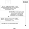
- FIG. 2 is a schematic structural diagram of UE according to an embodiment of this application.
- the UE may be a mobile phone, a tablet computer, a notebook computer, a netbook, a portable electronic device, or the like.
- the UE may include parts such as a memory, a processor, a radio frequency (Radio Frequency, RF) circuit, and a power supply.
- the memory may be configured to store a software program and a module.
- the processor runs the software program and the module that are stored in the memory, to execute various function applications of the UE and perform data processing.
- the memory may mainly include a program storage area and a data storage area.
- the program storage area may store an operating system, an application program required by at least one function, and the like, and the data storage area may store data created based on use of the UE, and the like.
- the memory may include a high-speed random access memory, and may further include a nonvolatile memory and the like.
- the processor is a control center of the UE, and is connected to all parts of the entire UE by using various interfaces and cables. The processor runs or executes the software program and/or the module stored in the memory, and invokes data stored in the memory, to perform various functions of the UE and process data, so that overall monitoring is performed on the UE.
- the processor may include one or more processing units.
- an application processor and a modem processor may be integrated into the processor.
- the application processor mainly processes an operating system, a user interface, an application program, and the like, and the modem processor mainly processes wireless communication.
- the RF circuit may be configured to receive and send information, or receive and send a signal during a call.
- the RF circuit includes but is not limited to an antenna, at least one amplifier, a transceiver, a coupler, an LNA (low noise amplifier, low noise amplifier), a duplexer, and the like.
- the UE further includes the power supply that supplies power to each part.
- the power supply may be logically connected to the processor by using a power management system, so as to implement functions such as charging management, discharging management, and power consumption management by using the power management system.
- the UE may further include an input unit, a display unit, a sensor module, an audio module, a WiFi module, a Bluetooth module, and the like, and details are not described herein.
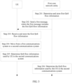
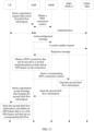
- FIG. 3 is a flowchart of a method for moving between communications systems according to an embodiment of this application.
- the method is applied to the communications system shown in FIG. 1 , and is used to move (move) UE from a first communications system to a second communications system.
- the method may include the following several steps.
- Step 201 A first core network entity determines first QoS flow information that is of the second communications system and that is corresponding to a first EPS bearer of the UE in the first communications system, and stores the first QoS flow information.
- a PDN connection in the first communications system is corresponding to a PDU session in the second communications system.
- One PDN connection may include a plurality of EPS bearers, and one PDU session may include a plurality of QoS flows.
- the UE may establish a plurality of PDN connections in the first communications system, and there may be one or more PDN connections that can be moved to the second communications system in the plurality of PDN connections.
- the PDN connection that can be moved to the second communications system means that a PGW used by the PDN connection is an SMF+PGW-C integrated in 4G and 5G; or means that when the UE moves from the first communications system to the second communications system, a PDU session corresponding to the PDN connection can be established in the second communications system, and the PDN connection has a same IP address as the PDU session; or means that a PGW used by the PDN connection is an SMF+PGW-C integrated in 4G and 5G and when the UE moves from the first communications system to the second communications system, a PDU session corresponding to the PDN connection can be established in the second communications system, and the PDN connection has a same IP address as the PDU session.
- the first EPS bearer is an EPS bearer included in the PDN connection established by the UE in the first communications system, and may be one EPS bearer or a group of EPS bearers.
- a first QoS flow is corresponding to the first EPS bearer, and the first QoS flow may include one QoS flow or a group of QoS flows.
- One EPS bearer may be corresponding to one or more QoS flows.
- the first QoS flow information is information obtained after the first EPS bearer is mapped to a QoS flow in the second communications system, for example, mapping is performed based on a predefined mapping rule. Alternatively, the first QoS flow information is generated based on the first EPS bearer.
- Not all EPS bearers on the UE can be moved to the second communications system.
- a non-GBR EPS bearer cannot be moved to the second communications system.
- none of EPS bearers corresponding to the PDN connection can be moved to the second communications system.
- An EPS bearer that cannot be moved to the second communications system has no corresponding QoS flow information.
- the first QoS flow information may include one or more QoS rules (rule).
- the first QoS flow information includes one or more of the following information: a session aggregation maximum bit rate (session AMBR), an SSC mode, a PDU session identifier, and a QoS rule.
- the QoS rule may be one QoS rule, or may be a plurality of QoS rules.
- the QoS rule includes one or more of the following information: a QoS rule identifier, a QoS flow identifier, precedence (precedence), or a packet filter (packet filter); or the QoS rule includes one or more of the following information: a QoS rule identifier, a QoS flow identifier, precedence, and a packet filter identifier.
- the packet filter includes a packet filter attribute (packet filter attribute) and a packet filter identifier (packet filter ID).
- the first QoS flow information may further include a combination of one or more of the following information: a 5QI, an ARP, a GFBR, an MFBR, and notification control that are of the QoS flow.
- a default bearer of the UE is set up in a process in which the UE establishes a PDN connection in the first communications system.
- to set up a default bearer for the UE may be understood as establishing a PDN connection for the UE.
- the UE may request, by using an attach (attach) request or a PDN connection establishment request (PDN Connectivity Request), to establish the PDN connection.
- PDN Connectivity Request PDN connection establishment request
- information about a PDU session that is of the second communications system and that is corresponding to the PDN connection is sent to the UE by using a request message used for setting up a default bearer.
- the information about the PDU session includes one or more of a session aggregation maximum bit rate (session AMBR), an SSC mode, and a PDU session identifier.
- a method used by the SMF+PGW-C to determine first QoS flow information of a 5G communications system may be:
- the SMF+PGW-C generates a 5G QoS rule based on a traffic flow template (TFT) of an EPS context.
- the method specifically includes: generating the QoS rule based on one or more policy and charging control (PCC) rules used for generating a TFT of an EPS bearer.
- PCC policy and charging control
- Precedence of each PCC is set to precedence of the QoS rule, and one or more packet filters of the PCC are set to a packet filter of the QoS rule.
- the SMF+PGW-C may further allocate a QoS rule identifier to the QoS rule.
- the SMF+PGW-C may further set a QCI of the EPS bearer to a 5G 5QI, set a GBR of the EPS bearer to a 5G GFBR, set an MBR of the EPS bearer to a 5G MFBR, and set an EBI of a default bearer of the PDN connection to a 5G PDU session identifier.
- the method may further include: obtaining, by the UE, a first QoS flow identifier (QFI).
- the first QoS flow identifier is obtained after the UE adds a specific value to a first EPS bearer identifier (EBI), or the first QoS flow identifier is obtained after the UE adds a specific field to a first EPS bearer identifier.
- EBI EPS bearer identifier
- a QFI is obtained after a specific value is added to an EBI, and for example, the specific value is 10. If the EBI is 5, the QFI is 15, and if the EBI is 6, the QFI is 16.
- a QFI is obtained after a specific field is added to an EBI, and for example, the specific field is one byte. If the EBI is one byte, the QFI is obtained after one byte is added after the EBI. If the one byte of the EBI is 00000101, the QFI is two bytes obtained after one byte is added: 00000101 00000001.
- the first core network entity stores the first QoS flow information may include: storing, by the first core network entity, a correspondence between the first EPS bearer identifier (EPS Bearer Identity, EBI) and the first QoS flow information; or storing, by the first core network entity, a correspondence between a first EPS bearer context and the first QoS flow information; or storing, by the first core network entity, a correspondence between the first QoS flow identifier and a first EPS bearer context; or storing, by the first core network entity, a correspondence between a first EPS bearer context and both the first QoS flow identifier and a session identifier, where the session identifier herein is an identifier of a PDU session to which the first QoS flow belongs; or storing a correspondence between the first EPS bearer and the first QoS flow; or storing a correspondence between the first EPS bearer and index information of the first QoS flow, where the index information includes the first QoS flow
- the first core network entity may store the first QoS flow information in a bearer context of the first EPS bearer of the UE; or the first core network entity generates a QoS flow context of the second communications system for the UE, and the QoS flow context includes an EBI or first EPS bearer information.
- the first communications system may be a 4G communications system
- the second communications system may be a 5G communications system
- the first core network entity may be a network element SMF+PGW-C integrated in the two communications systems, so that the SMF+PGW-C may determine first QoS flow information in the 5G communications system based on an EPS bearer context of the UE in the 4G communications system.
- the QoS flow information may also be referred to as a 5G QoS rule (Rule) or a 5G QoS parameter.
- the first QoS flow information includes a combination of one or more of the following information: QoS information of the QoS flow, a QoS flow identifier QFI, a QoS rule, information about a PDU session to which the QoS flow belongs, and a QoS flow template.
- the QoS information further includes a combination of one or more of the following information: a 5QI, an ARP, a GFBR, an MFBR, and notification control that are of the QoS.
- the SMF+PGW-C may generate QoS of a 5G QoS flow based on QoS of an EPS bearer in the first EPS bearer, and generate a 5G QoS flow template or a QoS rule based on a TFT of the EPS bearer.
- Step 202 The first core network entity sends a first message, where the first message is used to set up or modify the first EPS bearer for the UE in the first communications system, and the first message includes the first QoS flow information.
- the first core network entity may send the first message that includes the first QoS flow information to the UE, so that the UE obtains the first QoS flow information corresponding to the first EPS bearer.
- the foregoing step 201 specifically includes: The first core network entity maps (map) the first EPS bearer context to the first QoS flow information of the second communications system. If the first message is used to modify the first EPS bearer for the UE in the first communications system, the foregoing step 201 specifically includes: The first core network entity maps a context of the modified first EPS bearer to the first QoS flow information of the second communications system.
- the mapping described herein may be understood as generating the first QoS flow information based on the first EPS bearer context, or performing mapping based on a predefined mapping rule.
- the first QoS flow information may be the complete first QoS flow information obtained after the first core network entity performs mapping; or the first QoS flow information may be partial information of the first QoS flow information obtained after the first core network entity performs mapping, and the partial information is first QoS flow information that the UE cannot obtain through local mapping.
- the partial information includes partial QoS rule information and partial PDU session information.
- the partial QoS rule information includes one or more of a QoS rule ID, precedence (precedence), and a packet filter identifier
- the partial PDU session information includes one or more of a session AMBR, an SSC mode, and a PDU session identifier. Sending the partial information can reduce an amount of transmitted air interface data and save resources.
- the first core network entity SMF+PGW-C may send the first QoS flow information to the SGW by using the first message, the SGW forwards the first QoS flow information to the MME, and then the MME sends the first QoS flow information to the UE; or the first core network entity SMF+PGW-C may send the first QoS flow information to the SGW, the SGW forwards the first QoS flow information to the MME, and then the MME sends the first QoS flow information to the UE by using the first message.
- the first message may include a protocol configuration option PCO, and the first QoS flow information may be included in the PCO.
- the PCO may be a common PCO, or may be an extended (extended) PCO.
- the method further includes: allocating, by the first core network entity, a QoS flow identifier to the UE, to be specific, allocating a corresponding QoS flow identifier to the QoS flow included in the first QoS flow information determined in step 201; or mapping the bearer identifier of the first EPS bearer to a QoS flow identifier.
- the method further includes: determining, by the first core network entity, that the first EPS bearer has the corresponding first QoS flow information of the second communications system, to be specific, determining, by the first core network entity, whether the first EPS bearer of the UE in the first communications system has the corresponding first QoS flow information of the second communications system; and if the first core network entity determines that the first EPS bearer has the corresponding first QoS flow information, determining the first QoS flow information based on step 201.
- That the first EPS bearer has the corresponding first QoS flow information of the second communications system may be specifically understood as: Context information of the first EPS bearer includes the first QoS flow information, or the UE separately stores the first EPS bearer context and the first QoS flow information.
- the context information of the first EPS bearer includes index information of the first QoS flow, and the index information may be a QoS flow ID or a combination of a QoS flow ID and a PDU session ID.
- the QoS flow information and the information about the QoS flow have a same meaning, and another part of this specification has a same understanding. Details are not described.
- Step 203 When the UE receives the first message sent by the first core network entity, the UE may store the first QoS flow information.
- the UE may store the first QoS flow information.
- the UE may store the correspondence between the bearer identifier of the first EPS bearer and the first QoS flow information; or the UE stores the correspondence between the first EPS bearer context and the first QoS flow information; or the UE stores the correspondence between the first EPS bearer context and the index information of the first QoS flow, where the index information may be a QoS flow ID or a combination of a QoS flow ID and a PDU session ID; or the UE adds the first QoS flow information to the first EPS bearer context; or the UE separately stores the first EPS bearer context and the first QoS flow information, and the UE adds the index information of the first QoS flow to the context information of the first EPS bearer, where the index information may be a QoS flow ID or
- the UE may store the correspondence between the bearer identifier of the first EPS bearer and the first QoS flow information. This may be specifically understood as storing, in the first EPS bearer context, the correspondence between the bearer identifier of the first EPS bearer and the first QoS flow information. That the UE stores the correspondence between the first EPS bearer and the first QoS flow information may be specifically understood as storing the first QoS flow information in the first EPS bearer context, or adding the index information of the first QoS flow to the context information of the first EPS bearer, where the index information may be a QoS flow ID or a combination of a QoS flow ID and a PDU session ID.
- the PDU session ID herein is an ID of a PDU session to which a QoS flow belongs, to be specific, a PDU session indicated by the PDU session ID includes the first QoS flow.
- Step 204 The UE moves from the first communications system to the second communications system.
- the UE moves from the first communications system to the second communications system by using a handover process.
- the UE receives a handover command (handover command) in the handover process.
- the handover command includes index information of one or more QoS flows, and the index information includes a QoS flow identifier or a combination of a QoS flow identifier and a PDU session identifier.
- the handover command is sent by a base station in the first communications system to the UE, and the handover command includes configuration information allocated by a base station in the second communications system to the UE.
- the configuration information is used by the UE to access the base station in the second communications system.
- the configuration information includes a QoS flow identifier or a combination of a QoS flow identifier and a PDU session ID.
- Step 205 The UE determines, based on a first condition, QoS flow information used by the UE in the second communications system, where the first condition includes the first QoS flow information.
- the first QoS flow information in step 205 is consistent with the first QoS flow information in step 201.
- a method used by the UE to determine the first QoS flow information refer to descriptions in step 201. Details are not described herein again in this embodiment of this application.
- a method used by the UE to determine the QoS flow information used in the second communications system may be as follows: The UE associates a currently used EPS bearer with the index information that is of the QoS flow and that is included in the handover command, and the UE deletes an EPS bearer that is in the currently used EPS bearer and that fails to be associated with the index information of the QoS flow.
- the currently used EPS bearer may be understood as an ongoing (ongoing) EPS bearer on the UE, or an active-state EPS bearer on the UE.
- the UE associates a currently used EPS bearer with the index information that is of the QoS flow and that is included in the handover command includes: obtaining, by the UE, an EPS bearer context corresponding to the index information of the QoS flow; or obtaining, by the UE, an EPS bearer identifier corresponding to the index information of the QoS flow.
- the UE obtains the index information of the QoS flow from the handover command, and the UE locally searches for the EPS bearer context or the EPS bearer identifier corresponding to the index information.
- the UE locally deletes an EPS bearer other than an EPS bearer that can be found on the UE.
- Step 206 In a process in which the UE moves from the first communications system to the second communications system, or after the UE moves from the first communications system to the second communications system, the first core network entity determines, based on a fourth condition, the QoS flow information used by the UE in the second communications system, where the fourth condition includes the first QoS flow information.
- the QoS flow information used by the UE in the second communications system may be QoS flow information corresponding to one or more PDU sessions of the UE; or may be information about one or more PDU sessions of the UE, and when the QoS flow information includes information about a plurality of PDU sessions, corresponding information may be referred to as an information set.
- the QoS flow information may be understood as a set of one or more pieces of QoS flow information, or may be understood as a set of one or more pieces of PDU session information. It may be understood that if the QoS flow information includes only one piece of QoS flow information or only one piece of PDU session information, the set includes only one piece of QoS flow information or only one piece of PDU session information. Another part of this specification has a same understanding. Details are not described again.
- the UE and the first core network entity may determine, based on the first QoS flow information included in the first condition, the QoS flow information that may be used by the UE in the second communications system, so that the UE maps an EPS bearer in the first communications system to a QoS flow in the second communications system, and the UE is seamlessly transferred from the first communications system to the second communications system, and can communicate with or transmit data to the second communications system by using the QoS flow information.
- step 204 may first move from the first communications system to the second communications system, and then determine the QoS flow information used in the second communications system; or the UE first determines the QoS flow information used in the second communications system, and then moves from the first communications system to the second communications system; or in the process of moving from the first communications system to the second communications system, the UE determines the QoS flow information used in the second communications system.
- step 204 is performed before step 205 and step 206.
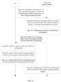
- step 201 the method further includes step 200a and step 200b.
- Step 200a The UE sends first information to the first core network entity in a process of establishing a PDN connection in the first communications system, where the first information is used by the first core network entity to determine that the PDN connection can be moved from the first communications system to the second communications system.
- the PDN connection may be established in an attach (Attach) process, or may be established based on a PDN connection establishment request requested by the UE.
- the first information includes information used to indicate that the PDN connection can be moved to the second communications system, to be specific, the first information includes information that is directly used to indicate that the PDN can be moved to the second communications system.
- the first information includes information used to indicate that a service and session continuity SSC mode of a PDU session corresponding to the PDN connection in the second communications system is a specified mode, and the specified mode may be preset.
- the first information includes information that is indirectly used to indicate that the PDN can be moved to the second communications system.
- the specified mode may be a mode 1 in the SSC mode, to be specific, when the first information includes information used to indicate that the SSC mode of the PDU session corresponding to the PDN connection in the second communications system is the mode 1, it indicates that the PDN connection can be moved to the second communications system.
- the UE may send the first information to the first core network entity by using a PCO, to be specific, the first information is included in the PCO.
- the PCO may be a common PCO, or may be an extended PCO.
- Step 200b When the first core network entity receives the first information sent by the UE, the first core network entity determines, based on the first information, that the PDN connection can be moved from the first communications system to the second communications system.
- the first core network entity when the first core network entity receives the first information sent by the UE, the first core network entity may directly determine that the PDN connection can be moved from the first communications system to the second communications system. If the first information includes the information used to indicate that the SSC mode of the PDU session corresponding to the PDN connection in the second communications system is the specified mode, when the first core network entity receives the first information sent by the UE, the first core network information determines whether the SSC mode indicated in the first information is the specified mode, and if the SSC mode is the specified mode, the first core network entity determines that the PDN connection can be moved from the first communications system to the second communications system.
- the method further includes step 201a and step 201b.
- a specific function of the SSC mode in FIG. 4 is different from a specific function of an SSC mode in FIG. 4A .
- the SSC mode in FIG. 4 is the specified mode, and is used to indicate that the PDN connection can be moved to the second communications system.
- the SSC mode in FIG. 4A is an SSC mode that is expected by the UE and that is of the PDU session corresponding to the PDN connection in the second communications system.
- Step 201a The UE sends second information to the first core network entity in a process of establishing a PDN connection in the first communications system, where the second information is used to indicate an SSC mode of a PDU session corresponding to the PDN connection in the second communications system.
- the UE may send the second information to the first core network entity by using a PCO, to be specific, the second information is included in the PCO.
- the PCO may be a common PCO, or may be an extended PCO.
- the UE may first send an attach (attach) request message or a PDU session create request message to an MME, and add the second information to a PCO of the message.
- the MME sends a session create request to the first core network entity by using an SGW, and the session create request carries the PCO.
- Step 201b The first core network entity receives the second information sent by the UE, where the second information is used to indicate an SSC mode of a PDU session corresponding to the PDN connection in the second communications system.
- the first core network entity may determine, based on the SSC mode indicated by the second information, the SSC mode of the PDU session corresponding to the PDN connection in the second communications system, or the first core network entity determines, based on the SSC mode indicated by the second information and based on subscription data of the UE, the SSC mode of the PDU session corresponding to the PDN connection in the second communications system.
- the determined SSC mode of the PDU session may be an indicated SSC mode, or may be another SSC mode.
- the determined SSC mode of the PDU session is 1; and if the UE requests an SSC mode 1, and subscription of the UE supports an SSC mode 2, the determined SSC mode of the PDU session is 2.
- the process in which the UE moves from the first communications system to the second communications system in step 204 may have two different cases based on whether the UE is in an idle (idle) state or a connected (connected) state.
- the two cases are separately described below. That the UE moves from the first communications system to the second communications system in an idle state is specifically:
- That the UE moves from the first communications system to the second communications system in a connected state is specifically: The UE moves to the second communications system by using a handover process. For example, when the base station in the first communications system receives a measurement report reported by the UE, and determines that the UE needs to be handed over to the base station in the second communications system, the base station in the first communications system initiates a handover process, and when the UE receives a handover command (handover command) sent by the base station in the first communications system, the UE moves from the first communications system to the second communications system.
- a handover process For example, when the base station in the first communications system receives a measurement report reported by the UE, and determines that the UE needs to be handed over to the base station in the second communications system, the base station in the first communications system initiates a handover process, and when the UE receives a handover command (handover command) sent by the base station in the first communications system, the UE moves from the first communications system to the second
- Case 1 The UE moves from the first communications system to the second communications system in an idle state.
- the UE may move from the first communications system to the second communications system in an idle state in the following two manners (I) and (II) that are specifically described as follows:
- the second condition includes the correspondence stored by the UE in step 203, to be specific, the correspondence between the EBI of the first EPS bearer and the first QoS flow information, or the correspondence between the first EPS bearer and the first QoS flow information.
- EPS bearer status information is a phrase, and the "first" in the first EPS bearer status information and the "second" in the second EPS bearer status information are used to define and differentiate between different EPS bearer status information.
- the first EPS bearer status information is used to identify an active-state (Active) EPS bearer that is of the UE and that has corresponding QoS flow information, to be specific, an EPS bearer identified in the first EPS bearer status information is an active-state EPS bearer that is of the UE and has corresponding QoS flow information and that is determined by the UE based on the correspondence.
- Active active-state
- the second EPS bearer status information is used to identify an active-state EPS bearer that is of the UE and has corresponding QoS flow information and that is determined by the second core network entity.
- the UE has four active-state EPS bearers in the first communications system, and EBIs corresponding to the four EPS bearers are separately 5, 6, 7, and 8.
- EPS bearers whose EBIs are 5 and 7 have corresponding QoS flow information
- EPS bearers whose EBIs are 6 and 8 have no corresponding QoS flow information.
- In the first EPS bearer status information reported by the UE only EPS bearers whose EBIs are 5 and 7 are identified as active-state, and other bearers are identified as inactive-state (inactive). Details are shown in the following Table 2.
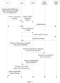
- the UE generates the first EPS bearer status information based on the second condition, and sends the first EPS bearer status information to the second core network entity.
- the second core network entity may receive the first EPS bearer status information, obtain a PDN connection context of the UE from a core network entity MME in the first communications system, and determine the second information based on a sixth condition.
- the sixth condition includes the first EPS bearer status information and the PDN connection context.
- the second core network entity sends the second information to the first core network entity, and the first core network entity generates, based on a fifth condition, the QoS flow information used by the UE in the second communications system.
- the QoS flow information includes QoS flow information corresponding to the active-state EPS bearer that is of the UE and that is determined by the second core network entity, and the fifth condition includes the second information and the correspondence stored by the first core network entity.
- the first core network entity may send third information to the second core network entity, where the third information is a generated bearer identifier of an EPS bearer corresponding to QoS flow information, so that the second core network entity generates the second EPS bearer status information based on a seventh condition, and sends the second EPS bearer status information to the UE by using the second message.
- the seventh condition includes the third information.
- the QoS flow information may be understood as a set of one or more pieces of QoS flow information, or may be understood as a set of one or more pieces of PDU session information. It may be understood that if the QoS flow information includes only one piece of QoS flow information or only one piece of PDU session information, the set includes only one piece of QoS flow information or only one piece of PDU session information. Another part of this specification has a same understanding. Details are not described again.
- the second information includes an EPS bearer identifier EBI that can be moved to the second communications system; or includes a linked bearer identifier (Linked Bearer ID, LBI) and an EPS bearer identifier EBI; or includes a PDN connection context, where the PDN connection context includes an EPS bearer context that can be moved to the second communications system.
- EBI EPS bearer identifier
- LBI linked Bearer ID
- EBI EPS bearer identifier
- PDN connection context includes an EPS bearer context that can be moved to the second communications system.
- the first core network entity If the second information includes the EPS bearer identifier EBI that can be moved to the second communications system, or includes the linked bearer identifier and the EPS bearer identifier, the first core network entity generates the QoS flow information based on the EPS bearer identifier EBI and the stored correspondence, or generates second QoS flow information based on the linked bearer identifier, the EPS bearer identifier, and the stored correspondence. If the second information includes the PDN connection context, the first core network entity maps the PDN connection context to second QoS flow information based on the stored correspondence.
- the first core network entity may be an SMF+PGW-C
- the second core network entity may be an AMF.
- the UE may send a registration request to the AMF, and the registration request may carry an identifier of the UE and the first EPS bearer status information.
- the AMF may obtain, based on the identifier of the UE, an MME that serves the UE, and request the MME for the PDN connection context of the UE.
- the AMF performs an authentication and authentication process on the UE, returns a PDN connection context acknowledgement message to the MME, and sends a location update request to a UDM+HSS, and the UDM+HSS returns a response message.
- the AMF obtains, based on the first EPS bearer status information sent by the UE and based on the PDN connection context obtained from the MME, a PDN connection that can be moved from the first communications system (for example, 4G) to the second communications system (for example, 5G) and an EPS bearer on the PDN connection, and obtains a corresponding SMF+PGW-C address.
- the AMF obtains a linked bearer identifier and a bearer identifier corresponding to the PDN connection that can be moved to the second communications system, and sends the linked bearer identifier and the bearer identifier to the SMF+PGW-C, and the SMF+PGW-C generates the second QoS flow information based on a stored correspondence, the linked bearer identifier, and the bearer identifier.
- the AMF obtains a PDN connection context that can be moved to the second communications system, and sends the PDN connection context to the SMF+PGW-C, and the SMF+PGW-C maps the received PDN connection context to the second QoS flow information based on a stored correspondence.
- the SMF+PGW-C sends, to the AMF, a generated bearer identifier of an EPS bearer corresponding to the second QoS flow information, so that the AMF generates the second EPS bearer status information based on the bearer identifier, and returns the second EPS bearer status information to the UE by using a registration accept message.
- step 205 specifically includes: The UE determines, based on the stored correspondence and the second EPS bearer status information, the QoS flow information used by the UE in the second communications system.
- a process in which the AMF obtains the PDN connection that can be moved from the first communications system (for example, 4G) to the second communications system (for example, 5G) and the EPS bearer on the PDN connection, and obtains the corresponding SMF+PGW-C address may include: The AMF obtains, based on an EPS bearer intersection set between the first EPS bearer status information and a bearer context in the PDN connection context, the PDN connection that can be moved to the second communications system and the EPS bearer on the PDN connection, and the AMF may obtain the SMF+PGW-C address based on the PDN connection context.
- an N1 session management information (N1 SM Information) parameter includes the first QoS flow information; or when the first message is a PDU session modification message, an N1 session management information parameter of the PDU session modification message includes the first QoS flow information.
- the UE generates first QoS flow status information based on a third condition, and sends the first QoS flow status information to a second core network entity, so that the second core network entity returns a second message.
- the second message includes second QoS flow status information
- the second core network entity is a core network entity that is in the second communications system and that is responsible for UE access and mobility management. Accordingly, the first condition in step 205 may further include the second QoS flow status information.
- the third condition includes the correspondence stored by the UE in step 203, to be specific, the correspondence between the EBI of the first EPS bearer and the first QoS flow information, or the correspondence between the first EPS bearer context and the first QoS flow information, or the correspondence between the first EPS bearer context and the index information of the first QoS flow.
- QoS flow status information is a phrase, and the "first" in the first QoS flow status information and the "second" in the second QoS flow status information are used to define and differentiate between different QoS flow status information.
- the first QoS flow status information is used to identify a QoS flow corresponding to an active-state EPS bearer of the UE, to be specific, a QoS flow identified in the first QoS flow status information is a QoS flow that is corresponding to an active-state EPS bearer and that is determined by the UE based on the correspondence.
- the second QoS flow status information is used to identify a QoS flow that is corresponding to an active-state EPS bearer of the UE and that is determined by the second core network entity.
- the QoS flow corresponding to the active-state EPS bearer of the UE may be understood as a QoS flow corresponding to an active-state EPS bearer that has the corresponding QoS flow.
- the active-state EPS bearer may be understood as an EPS bearer that is in an active state and that has a corresponding QoS flow.
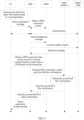
- the UE generates the first QoS flow status information based on the third condition, and sends the first QoS flow status information to the second core network entity.
- the second core network entity receives the first QoS flow status information, obtains a PDN connection context of the UE from a core network entity MME in the first communications system, and sends the first QoS flow status information and the PDN connection context to the first core network entity, so that the first core network entity generates second QoS flow information of the UE in the second communications system based on a fifth condition.
- the fifth condition includes the first QoS flow status information and the PDN connection context.
- the first core network entity may return the second QoS flow information to the second core network entity, so that the second core network entity generates the second QoS flow status information, to be specific, the second information determined by the second core network entity, and returns the second QoS flow status information to the UE by using the second message.
- the first core network entity may be an SMF+PGW-C
- the second core network entity may be an AMF.
- the UE may send a registration request to the AMF, and the registration request may carry an identifier of the UE and the first QoS flow status information.
- the AMF may obtain, based on the identifier of the UE, an MME that serves the UE, and request the MME for the PDN connection context of the UE.
- the AMF performs an authentication and authentication process on the UE, returns a PDN connection context acknowledgement message to the MME, and sends a location update request to a UDM+HSS, and the UDM+HSS returns a response message.
- the AMF learns, based on the SMF+PGW-C that is in the PDN connection context and that is a network element shared by the first communications system (for example, 4G) and the second communications system (for example, 5G), that the PDN connection can be moved to the second communications system.
- the AMF sends the obtained PDN connection context and the first QoS flow status information to the SMF+PGW-C.
- the SMF+PGW-C maps the PDN connection context to QoS flow information, determines, as the second QoS flow information, an intersection set between the first QoS flow status information and the QoS flow information obtained through mapping, and may further delete a QoS flow that is not described in the QoS flow information. Then, the SMF+PGW-C returns the second QoS flow information to the AMF, and the AMF generates the second QoS flow status information based on the second QoS flow information, and returns the second QoS flow status information to the UE by using a registration accept message.
- step 205 specifically includes: The UE determines, based on the stored correspondence and the second QoS flow status information, the QoS flow information used by the UE in the second communications system.
- first EPS bearer status information and the first QoS flow status information may be collectively referred to as first status information
- second EPS bearer status information and the second QoS flow status information may be collectively referred to as second status information.
- a process in which the UE moves from the first communications system to the second communications system in a connected state may include: The UE receives a handover command (Handover Command) sent by the base station in the first communications system, where the handover command includes a session identifier and a QoS flow identifier. Accordingly, the first condition in step 205 may further include the session identifier and the QoS flow identifier.
- Handover Command handover command
- the first condition in step 205 may further include the session identifier and the QoS flow identifier.
- the first core network entity may be an SMF+PGW-C
- the second core network entity may be an AMF.
- the base station for example, a 4G base station
- the base station determines that the UE needs to move from the first communications system to the second communications system
- the base station sends a handover request to the core network entity MME in the first communications system.
- the MME receives the handover request
- the MME sends a relocation (Relocation) request to the core network entity AMF in the second communications system, and the relocation request includes a PDN connection context of the UE.
- Relocation relocation
- the AMF obtains, based on the PDN connection context, an SMF+PGW-C that serves the UE, and sends a session management (Session Management, SM) context request message to the SMF+PGW-C.
- the request message includes the PDN connection context.
- the SMF+PGW-C determines, based on the PDN connection context and the stored correspondence, PDU session information (which may also be a PDU session context) that is in the second communications system and that is corresponding to the PDN connection context. Then, the SMF+PGW-C sends an N4 session create request to a UPF+PGW-U, and sends an SM context response message to the AMF.
- the response message includes the PDU session information.
- the AMF sends a handover request to the base station in the second communications system, and the handover request includes the PDU session information.
- the base station in the second communications system returns, to the AMF, radio resource information allocated to the UE.
- the AMF sends an SM context update message to the SMF+PGW-C, and the update message is used to create a tunnel between the UPF+PGW-U and the base station in the second communications system.
- the AMF sends a location update response message to the MME, and the response message includes the radio resource information allocated by the base station in the second communications system to the UE.
- the MME sends a forwarding tunnel create request to an SGW, and sends, to the base station in the first communications system, a handover command that includes the radio resource information allocated to the UE.
- the base station in the first communications system sends a handover command to the UE.
- the handover command includes the radio resource information allocated to the UE, and the radio resource information includes a session identifier and a QoS flow identifier.
- a process in which the SMF sends the SM context request message to the SMF+PGW-C and the SMF+PGW-C determines the PDU session information in the second communications system may include: The AMF obtains a PDN connection that can be moved from the first communications system to the second communications system and an EPS bearer on the PDN connection, and obtains a corresponding SMF+PGW-C address, a linked bearer identifier, and a bearer identifier, the AMF sends the linked bearer identifier and the bearer identifier to the SMF+PGW-C, and the SMF+PGW-C determines the PDU session information based on the linked bearer identifier, the bearer identifier, and a stored correspondence; or the AMF obtains a PDN connection that can be moved from the first communications system to the second communications system and an EPS bearer on the PDN connection, and obtains a corresponding SMF+PGW-C address and a PDN connection context including an EPS bear
- step 205 specifically includes: The UE determines, based on the first QoS flow information, the session identifier, and the QoS flow identifier, the QoS flow information used by the UE in the second communications system.
- step 203 and before step 204 after the UE receives the first message and before the UE moves from the first communications system to the second communications system, the method further includes step 203a and step 203b.
- Step 203a The UE receives a fourth message, where the fourth message is used to delete the first EPS bearer.
- the fourth message may be sent to the UE by the MME in the first communications system shown in FIG. 1 .
- the MME sends, to the UE, the fourth message used to instruct the UE to delete the first EPS bearer.
- Step 203b The UE deletes the first EPS bearer and the first QoS flow information corresponding to the first EPS bearer.
- the UE deletes the first QoS flow information corresponding to the first EPS bearer
- the UE if the UE stores the first QoS flow information in step 203, the UE deletes the stored first QoS flow information; if the UE stores, in step 203, the correspondence between the bearer identifier of the first EPS bearer and the first QoS flow information, or the correspondence between the first EPS bearer context and the first QoS flow information, or the correspondence between the first EPS bearer context and the index information of the first QoS flow, the UE deletes the stored correspondence.
- the method may further include step 205a.
- FIG. 8 is merely described based on FIG. 4 as an example, and the method for moving between communications systems shown in FIG. 5 is also applicable.
- Step 205a The UE deletes a second EPS bearer context, where a second EPS bearer is an EPS bearer that is on the UE and that has no corresponding QoS flow information.
- the UE instructs, by using the first information, the first core network entity to determine the first QoS flow information that is of the second communications system and that is corresponding to the first EPS bearer of the UE in the first communications system. Then, the first core network entity determines and stores the first QoS flow information, and sends the first QoS flow information to the UE by using the first message.
- the UE and the first core network entity may determine, based on the first QoS flow information, the QoS flow information used by the UE in the second communications system, so that when the UE moves from the first communications system to the second communications system, mapping between the first EPS bearer and the first QoS flow information is implemented, and active bearers are aligned, so as to ensure that the UE is seamlessly transferred to the second communications system.
- FIG. 9 is a flowchart of a method for moving between communications systems according to an embodiment of this application. Referring to FIG. 9 , the method is applied to the communications system shown in FIG. 1 , and is used to move (move) UE from a first communications system to a second communications system. The method may include the following several steps.
- Step 301 The UE sets up a first EPS bearer in the first communications system, and moves from the first communications system to the second communications system.
- a PDN connection in the first communications system is corresponding to a PDU session in the second communications system.
- One PDN connection may include a plurality of EPS bearers, and one PDU session may include a plurality of QoS flows.
- the UE may establish a plurality of PDN connections in the first communications system, and there may be one or more PDN connections that can be moved to the second communications system in the plurality of PDN connections.
- the PDN connection that can be moved to the second communications system means that a PGW used by the PDN connection is an SMF+PGW-C integrated in 4G and 5G; or means that when the UE moves from the first communications system to the second communications system, a PDU session corresponding to the PDN connection can be established in the second communications system, and the PDN connection has a same IP address as the PDU session; or means that a PGW used by the PDN connection is an SMF+PGW-C integrated in 4G and 5G, and when the UE moves from the first communications system to the second communications system, a PDU session corresponding to the PDN connection can be established in the second communications system, and the PDN connection has a same IP address as the PDU session.
- the first EPS bearer is an EPS bearer included in the PDN connection established by the UE in the first communications system, and may be one EPS bearer or a group of EPS bearers.
- the first communications system may be a 4G communications system
- the second communications system may be a 5G communications system, so that the UE may set up a first EPS bearer in the 4G communications system, and move from the 4G communications system to the 5G communications system after setting up the first EPS bearer.
- Step 302 The UE receives a first message, where the first message includes first QoS flow information that is of the second communications system and that is corresponding to the first EPS bearer.
- a first QoS flow is corresponding to the first EPS bearer, and the first QoS flow may include one QoS flow or a group of QoS flows.
- the first QoS flow information is information obtained after the first EPS bearer is mapped to a QoS flow in the second communications system, and the first QoS flow information includes QoS information of the QoS flow, for example, mapping is performed based on a predefined mapping rule. Alternatively, the first QoS flow information is generated based on the first EPS bearer.
- the first QoS flow information is a combination of one or more of the following information: a QoS flow identifier QFI and a QoS flow template.
- the QoS information may further include a combination of one or more of the following information: a 5QI, an ARP, a GFBR, an MFBR, and notification control that are of the QoS.
- Not all EPS bearers on the UE can be moved to the second communications system.
- a non-GBR EPS bearer cannot be moved to the second communications system.
- none of EPS bearers corresponding to the PDN connection can be moved to the second communications system.
- An EPS bearer that cannot be moved to the second communications system has no corresponding QoS flow information.
- the first QoS flow information may include one or more QoS rules (rule).
- the first QoS flow information includes one or more of the following information: a session aggregation maximum bit rate (session AMBR), an SSC mode, a PDU session identifier, and a QoS rule.
- the QoS rule may be one QoS rule, or may be a plurality of QoS rules.
- the QoS rule includes one or more of the following information: a QoS rule identifier, a QoS flow identifier, precedence (precedence), or a packet filter (packet filter); or the QoS rule includes one or more of the following information: a QoS rule identifier, a QoS flow identifier, precedence, and a packet filter identifier.
- the packet filter includes a packet filter attribute and a packet filter identifier.
- the first QoS flow information may further include a combination of one or more of the following information: a 5QI, an ARP, a GFBR, an MFBR, and notification control that are of the QoS flow.
- a default bearer of the UE is set up in a process in which the UE establishes a PDN connection in the first communications system.
- to set up a default bearer for the UE may be understood as establishing a PDN connection for the UE.
- the UE may request, by using an attach (attach) request or a PDN connection establishment request (PDN Connectivity Request), to establish the PDN connection.
- PDN Connectivity Request PDN connection establishment request
- information about a PDU session that is of the second communications system and that is corresponding to the PDN connection is sent to the UE by using a request message used for setting up a default bearer.
- the information about the PDU session includes one or more of a session aggregation maximum bit rate (session AMBR), an SSC mode, and a PDU session identifier.
- a method used by an SMF+PGW-C to determine first QoS flow information of the 5G communications system may be:
- the SMF+PGW-C generates a 5G QoS rule based on a traffic flow template (TFT) of an EPS context.
- the method specifically includes: generating the QoS rule based on one or more policy and charging control (PCC) rules used for generating a TFT of an EPS bearer.
- PCC policy and charging control
- Precedence of each PCC is set to precedence of the QoS rule, and one or more packet filters of the PCC are set to a packet filter of the QoS rule.
- the SMF+PGW-C may further allocate a QoS rule identifier to the QoS rule.
- the SMF+PGW-C may further set a QCI of the EPS bearer to a 5G 5QI, set a GBR of the EPS bearer to a 5G GFBR, set an MBR of the EPS bearer to a 5G MFBR, and set an EBI of a default bearer of the PDN connection to a 5G PDU session identifier.
- the method may further include: obtaining, by the UE, a first QoS flow identifier (QFI).
- QFI QoS flow identifier
- the first QoS flow identifier is obtained after the UE adds a specific value to a first EPS bearer identifier (EBI), or the first QoS flow identifier is obtained after the UE adds a specific field to a first EPS bearer identifier.
- a QFI is obtained after a specific value is added to an EBI, and for example, the specific value is 10. If the EBI is 5, the QFI is 15, and if the EBI is 6, the QFI is 16.
- a QFI is obtained after a specific field is added to an EBI, and for example, the specific field is one byte. If the EBI is one byte, the QFI is obtained after one byte is added after the EBI. If the one byte of the EBI is 00000101, the QFI is two bytes obtained after one byte is added: 00000101 00000001.
- the first message may be sent by a second core network entity to the UE.
- the second core network entity may determine the first QoS flow information, and send the first QoS flow information to the UE by using the first message, so that the UE receives the first message, sent by the second core network entity, that includes the first QoS flow information that is of the second communications system and that is corresponding to the first EPS bearer.
- the second core network entity may be a core network entity that is in the second communications system and that is responsible for UE access and mobility management, and the second core network entity may be the AMF in the second communications system shown in FIG. 1 .
- the first message may be a registration accept message, and an N1 session management information (N1 SM Information) parameter of the registration accept message includes the first QoS flow information; or the first message is a PDU session modification message, and an N1 session management information parameter of the PDU session modification message includes the first QoS flow information.
- the first message is a handover command (Handover Command) message, and the handover command message includes the first QoS flow information.
- QoS flow information in the 5G communications system may also be referred to as a 5G QoS parameter.
- a target to source transparent container of the handover command message includes the first QoS flow information.
- An access (Access) stratum of the UE may obtain the first QoS flow information from the target to source transparent container, and send the first QoS flow information to a non-access (Non-Access) stratum of the UE.
- the first message may further include information about the first EPS bearer corresponding to the first QoS flow information, and the information about the first EPS bearer may include a bearer identifier of the first EPS bearer.
- the second core network entity may add the information about the first EPS bearer and the first QoS flow information to the first message, and send the information about the first EPS bearer and the first QoS flow information to the UE by using the first message.
- Step 303 The UE determines, based on a first condition, QoS flow information used by the UE in the second communications system, where the first condition includes the first QoS flow information.
- the QoS flow information used by the UE in the second communications system may be QoS flow information corresponding to one or more PDU sessions of the UE, or may be information about one or more PDU sessions of the UE. This is not specifically limited in this embodiment of this application.
- the UE determines, based on the first QoS flow information included in the first condition, the QoS flow information that can be used by the UE in the second communications system, so that mapping between an EPS bearer of the UE in the first communications system and a QoS flow in the second communications system is implemented, and the UE is seamlessly transferred from the first communications system to the second communications system.
- step 303 there may be no sequence between step 303 and a process in which the UE moves from the first communications system to the second communications system in step 301.
- the UE may first move from the first communications system to the second communications system, and then determine the QoS flow information used in the second communications system; or the UE first determines the QoS flow information used in the second communications system, and then moves from the first communications system to the second communications system; or in the process of moving from the first communications system to the second communications system, the UE determines the QoS flow information used in the second communications system.
- the process in which the UE moves from the first communications system to the second communications system is before step 303.
- the process in which the UE moves from the first communications system to the second communications system in step 301 may have two different cases based on whether the UE is in an idle (idle) state or a connected (connected) state.
- the two cases are separately described below. That the UE moves from the first communications system to the second communications system in an idle state is specifically:
- That the UE moves from the first communications system to the second communications system in a connected state is specifically: The UE moves to the second communications system by using a handover process. For example, when the base station in the first communications system receives a measurement report reported by the UE, and determines that the UE needs to be handed over to the base station in the second communications system, the base station in the first communications system initiates a handover process, and when the UE receives a handover command sent by the base station in the first communications system, the UE moves from the first communications system to the second communications system.
- a handover process For example, when the base station in the first communications system receives a measurement report reported by the UE, and determines that the UE needs to be handed over to the base station in the second communications system, the base station in the first communications system initiates a handover process, and when the UE receives a handover command sent by the base station in the first communications system, the UE moves from the first communications system to the second communications system.
- Case 1 The UE moves from the first communications system to the second communications system in an idle state.
- the UE may move from the first communications system to the second communications system in an idle state in the following two manners (1) and (2) that are specifically described as follows:
- EPS bearer status information is a phrase, and the "first" in the first EPS bearer status information and "second" in second EPS bearer status information are used to define and differentiate between different EPS bearer status information.
- the first EPS bearer status information is used to identify an active-state EPS bearer, to be specific, an EPS bearer identified in the first EPS bearer status information is an active-state EPS bearer that is determined by the UE. For example, the UE has four active-state EPS bearers in the first communications system, and EBIs corresponding to the four EPS bearers are separately 5, 6, 7, and 8.
- EPS bearers whose EBIs are 5 and 7 have corresponding QoS flow information
- EPS bearers whose EBIs are 6 and 8 have no corresponding QoS flow information.
- the first EPS bearer status information reported by the UE only EPS bearers whose EBIs are 5 and 7 are identified as active-state, and other bearers are identified as inactive-state (inactive). Details are shown in the foregoing Table 2.
- the UE may determine a first EPS bearer status based on the active-state EPS bearer, and send the first EPS bearer status to the second core network entity.
- the second core network entity receives the first EPS bearer status information, obtains a PDN connection context that includes all PDN connections of the UE from a core network entity MME in the first communications system, determines second information based on the first EPS bearer status information and the PDN connection context, and obtains a PDN connection context corresponding to an EPS that can be moved to the second communications system.
- the second information includes the EPS bearer that can be moved to the second communications system.
- the second core network entity sends the obtained PDN connection context to the first core network entity, so that the first core network entity generates the QoS flow information used by the UE in the second communications system.
- the QoS flow information includes QoS flow information that is corresponding to an active-state EPS bearer of the UE and that is determined by the first core network entity.
- the first core network entity may send second QoS flow information to the second core network entity, so that the second core network entity sends the second QoS flow information to the UE.
- the QoS flow information may be understood as a set of one or more pieces of QoS flow information, or may be understood as a set of one or more pieces of PDU session information.
- the QoS flow information includes only one piece of QoS flow information or only one piece of PDU session information
- the set includes only one piece of QoS flow information or only one piece of PDU session information.
- the first core network entity may be an SMF+PGW-C
- the second core network entity may be an AMF.
- the UE may send a registration request to the AMF, and the registration request may carry an identifier of the UE and the first EPS bearer status information.
- the AMF may obtain, based on the identifier of the UE, an MME that serves the UE, and request the MME for the PDN connection context of the UE.
- the AMF performs an authentication and authentication process on the UE, returns a PDN connection context acknowledgement message to the MME, and sends a location update request to a UDM+HSS, and the UDM+HSS returns a response message.
- the AMF obtains, based on the first EPS bearer status information sent by the UE and based on the PDN connection context obtained from the MME, a PDN connection that can be moved from the first communications system (for example, 4G) to the second communications system (for example, 5G) and an EPS bearer on the PDN connection, and obtains a corresponding SMF+PGW-C address and a corresponding PDN connection context.
- the AMF obtains the PDN connection context that can be moved to the second communications system, and sends the PDN connection context to the SMF+PGW-C.
- the SMF+PGW-C generates the second QoS flow information based on the received PDN connection context.
- the SMF+PGW-C sends the second QoS flow information to the AMF, so that the AMF returns the second QoS flow information to the UE by using a registration accept message.
- the UE may store the second QoS flow information, and delete an EPS bearer that is in the first EPS bearer and that has no corresponding QoS flow.
- step 303 specifically includes: The UE determines, based on the first QoS flow information and the second QoS flow information, the QoS flow information used by the UE in the second communications system.
- a process in which the AMF obtains the PDN connection that can be moved from the first communications system (for example, 4G) to the second communications system (for example, 5G) and the EPS bearer on the PDN connection, and obtains the corresponding SMF+PGW-C address may include: The AMF obtains, based on an EPS bearer intersection set between the first EPS bearer status information and a bearer context in the PDN connection context, the PDN connection that can be moved to the second communications system and the EPS bearer on the PDN connection, and the AMF obtains the SMF+PGW-C address based on the PDN connection context that can be moved to the second communications system.
- the UE generates first QoS flow status information based on a second condition, where the second condition includes an active-state EPS bearer of the UE, and the UE sends the first QoS flow status information to the second core network entity.
- QoS flow status information is a phrase, and the "first" in the first QoS flow status information and "second" in the following second QoS flow status information are used to define and differentiate between different QoS flow status information.
- the first QoS flow status information is used to identify a QoS flow corresponding to an active-state EPS bearer of the UE, to be specific, a QoS flow identified in the first QoS flow status information is a QoS flow that is corresponding to an active-state EPS bearer and that is determined by the UE based on the correspondence.
- the second QoS flow status information is used to identify a QoS flow that is corresponding to an active-state EPS bearer of the UE and that is determined by the second core network entity.
- the UE generates the first QoS flow status information based on the active-state EPS bearer of the UE, and sends the first QoS flow status information to the second core network entity.
- the second core network entity receives the first QoS flow status information, obtains a PDN connection context of the UE from a core network entity MME in the first communications system, and sends the first QoS flow status information and the PDN connection context to the first core network entity, so that the first core network entity generates second QoS flow information of the UE in the second communications system based on the first QoS flow status information and the PDN connection context.
- the first core network entity may return the second QoS flow information to the second core network entity, so that the second core network entity sends the second QoS flow information to the UE by using a registration accept message.
- the first core network entity may be an SMF+PGW-C
- the second core network entity may be an AMF.
- the UE may send a registration request to the AMF, and the registration request may carry an identifier of the UE and the first QoS flow status information.
- the AMF may obtain, based on the identifier of the UE, an MME that serves the UE, and request the MME for the PDN connection context of the UE.
- the AMF performs an authentication and authentication process on the UE, returns a PDN connection context acknowledgement message to the MME, and sends a location update request to a UDM+HSS, and the UDM+HSS returns a response message.
- the AMF learns, based on the SMF+PGW-C that is in the PDN connection context and that is a network element shared by the first communications system (for example, 4G) and the second communications system (for example, 5G), that the PDN connection can be moved to the second communications system.
- the AMF sends the obtained PDN connection context and the first QoS flow status information to the SMF+PGW-C.
- the SMF+PGW-C maps the PDN connection context to QoS flow information, determines, as the second QoS flow information, an intersection set between the first QoS flow status information and the QoS flow information obtained through mapping, and may further delete a QoS flow that is not described in the QoS flow information. Then, the SMF+PGW-C returns the second QoS flow information to the AMF, and the AMF generates the second QoS flow status information based on the second QoS flow information, and returns the second QoS flow status information to the UE by using the registration accept message. Further, the UE may store the second QoS flow information, and delete an EPS bearer that is in the first EPS bearer and that has no corresponding QoS flow.
- step 303 specifically includes: The UE determines, based on the first QoS flow information and the second QoS flow information, the QoS flow information used by the UE in the second communications system.
- Case 2 A process in which the UE moves from the first communications system to the second communications system in a connected state may include: The UE receives a handover command sent by the base station in the first communications system, where the handover command includes a session identifier and a QoS flow identifier.
- the first core network entity may be an SMF+PGW-C
- the second core network entity may be an AMF.
- the base station for example, an E-UTRAN
- the base station determines that the UE needs to move from the first communications system to the second communications system
- the base station sends a handover request to the core network entity MME in the first communications system.
- the MME receives the handover request
- the MME sends a relocation (Relocation) request to the core network entity AMF in the second communications system, and the relocation request includes a PDN connection context of the UE.
- the AMF obtains, based on the PDN connection context, an SMF+PGW-C that serves the UE, and sends a session management (Session Management, SM) context request message to the SMF+PGW-C.
- the request message includes the PDN connection context.
- the SMF+PGW-C determines, based on the PDN connection context, a PDU session context that is in the second communications system and that is corresponding to the PDN connection context. Then, the SMF+PGW-C sends an N4 session create request to a UPF+PGW-U, and sends an SM context response message to the AMF.
- the response message includes PDU session information.
- the AMF sends a handover request to the base station in the second communications system, and the handover request includes the PDU session information.
- the base station in the second communications system returns, to the AMF, radio resource information allocated to the UE.
- the AMF sends an SM context update message to the SMF+PGW-C, and the update message is used to create a tunnel between the UPF+PGW-U and the base station in the second communications system.
- the AMF sends a location update response message to the MME, and the response message includes the PDU session context and the radio resource information that is allocated by the base station in the second communications system to the UE.
- the MME sends a forwarding tunnel create request to an SGW, and sends, to the base station in the first communications system, a handover command including the PDU session context and the radio resource information that is allocated to the UE.
- the base station in the first communications system sends a handover command to the UE.
- the handover command includes the PDU session context and the radio resource information that is allocated to the UE, and the radio resource information includes a session identifier and a QoS flow identifier.
- a process in which the AMF sends the PDU session context to the UE may further be: The AMF sends the PDU session context to the base station in the second communications system, and the base station in the second communications system encapsulates the PDU session context in a target to source transparent container and sends the PDU session context to the AMF. Then, the AMF sends the PDU session context to the UE by using the MME and the base station in the first communications system.
- a process in which the AMF allocates the radio resource information to the UE is consistent with the foregoing description.
- a process in which the SMF sends the SM context request message to the SMF+PGW-C and the SMF+PGW-C determines the PDU session information in the second communications system may include: The AMF obtains a PDN connection that can be moved from the first communications system to the second communications system and an EPS bearer on the PDN connection, and obtains a corresponding SMF+PGW-C address, a linked bearer identifier, and a bearer identifier, the AMF sends the linked bearer identifier and the bearer identifier to the SMF+PGW-C, and the SMF+PGW-C determines the PDU session information based on the linked bearer identifier, the bearer identifier, and a stored correspondence; or the AMF obtains a PDN connection that can be moved from the first communications system to the second communications system and an EPS bearer on the PDN connection, and obtains a corresponding SMF+PGW-C address and a PDN connection context including an EPS bear
- step 303 specifically includes: The UE determines, based on the first QoS flow information, the session identifier, and the QoS flow identifier, the QoS flow information used by the UE in the second communications system.
- the method may further include step 304.
- Step 304 The UE deletes a second EPS bearer context, where a second EPS bearer is an EPS bearer that is not included in the first message, or a second EPS bearer is an EPS bearer that is of the UE and that has no corresponding QoS flow information.
- the UE sets up the first EPS bearer in the first communications system, moves from the first communications system to the second communications system, receives the first QoS flow information that is corresponding to the first EPS bearer and that is sent by the second core network entity, and determines, based on the first condition that includes the first QoS flow information, the QoS flow information used by the UE in the second communications system, so that when the UE moves from the first communications system to the second communications system, mapping between the first EPS bearer and the first QoS flow information is implemented, and active bearers are aligned, so as to ensure that the UE is seamlessly transferred to the second communications system.
- each network element such as the user equipment UE, the first core network device, or the second core network device includes a corresponding hardware structure and/or software module used to perform the functions.
- network elements and algorithm steps in the examples described with reference to the embodiments disclosed in this specification may be implemented in a form of hardware or in a form of a combination of hardware and computer software in this application. Whether a function is implemented by hardware or is implemented in a manner in which computer software drives hardware depends on a particular application and a design constraint of a technical solution. A person skilled in the art may use different methods to implement the described functions for each particular application, but it should not be considered that such implementation goes beyond the scope of this application.
- the user equipment, the first core network device, and the second core network device may be divided into function modules based on the foregoing method examples.
- each function module may be obtained through division for each function, or two or more functions may be integrated into one processing module.
- the integrated module may be implemented in a form of hardware, or may be implemented in a form of a software function module. It should be noted that the module division in the embodiments of this application is an example, and is merely logical function division and there may be another division manner in actual implementation.
- FIG. 14 is a possible schematic structural diagram of user equipment involved in the foregoing embodiments.
- User equipment 300 includes a receiving unit 301, a storage unit 302, a moving unit 303, and a determining unit 304.
- the receiving unit 301 is configured to perform the step of receiving the first QoS flow information in FIG. 3 , FIG. 4 , or FIG. 8 .
- the storage unit 302 is configured to perform the step of storing the first QoS flow information in FIG. 3 , FIG. 4 , or FIG. 8 .
- the moving unit 303 is configured to perform step 204 in FIG. 3 , FIG. 4 , or FIG. 8 .
- the determining unit 304 is configured to perform step 205 in FIG. 3 , FIG.
- the user equipment 300 further includes a sending unit 305 and/or a deletion unit 306.
- the sending unit 305 is configured to perform step 200a in FIG. 4 or FIG. 8 and step 201a in FIG. 4A .
- the deletion unit 306 is configured to perform step 205a in FIG. 8 . All related content of the steps involved in the foregoing method embodiments may be cited in function descriptions of corresponding function modules, and details are not described herein again.
- the moving unit 303, the determining unit 304, and the deletion unit 306 may be processors
- the receiving unit 301 may be a receiver
- the sending unit 305 may be a transmitter.
- the transmitter and the receiver may form a communications interface.
- FIG. 15 is a possible schematic logical structure diagram of user equipment 310 involved in the foregoing embodiment according to an embodiment of this application.
- the user equipment 310 includes a processor 312, a communications interface 313, a memory 311, and a bus 314.
- the processor 312, the communications interface 313, and the memory 311 are connected to each other by using the bus 314.
- the processor 312 is configured to control and manage an action of the user equipment 310.
- the processor 312 is configured to perform step 203 and step 204 in FIG. 3 , FIG. 4 , or FIG. 8 , step 205a in FIG. 8 , and/or another process of the technology described in this specification.
- the communications interface 313 is configured to support communication of the user equipment 310.
- the memory 311 is configured to store program code and data of the user equipment 310.
- the processor 312 may be a central processing unit, a general-purpose processor, a digital signal processor, an application-specific integrated circuit, a field programmable gate array or another programmable logic device, a transistor logic device, a hardware component, or any combination thereof.
- the processor 312 may implement or execute various example logical blocks, modules, and circuits described with reference to content disclosed in this application.
- the processor may be a combination for implementing a computing function, for example, a combination of one or more microprocessors, or a combination of a digital signal processor and a microprocessor.
- the bus 314 may be a peripheral component interconnect (Peripheral Component Interconnect, PCI) bus or an extended industry standard architecture (Extended Industry Standard Architecture, EISA) bus, or the like.
- PCI peripheral component interconnect
- EISA Extended Industry Standard Architecture
- FIG. 16 is a possible schematic structural diagram of a first core network device involved in the foregoing embodiments.
- a first core network device 400 includes a determining unit 401, a sending unit 402, and a storage unit 403.
- the determining unit 401 is configured to perform the step of determining the first QoS flow information in step 201 in FIG. 3 or FIG. 4 , or the step of determining the first QoS flow information in step 200b and step 201 in FIG. 8 .
- the sending unit 402 is configured to perform step 202 in FIG. 3 , FIG. 4 , or FIG. 8 .
- the storage unit 403 is configured to perform the step of storing the first QoS flow information in step 201 in FIG. 3 , FIG. 4 , or FIG. 8 .
- the first core network device 400 further includes a receiving unit 404, and the receiving unit 404 is configured to perform the step of receiving the first information sent by the UE in FIG. 4 , step 201b in FIG. 4A , and/or another process of the technology described in this specification. All related content of the steps involved in the foregoing method embodiments may be cited in function descriptions of corresponding function modules, and details are not described herein again.
- FIG. 17 is a possible schematic logical structure diagram of a first core network device 410 involved in the foregoing embodiment according to an embodiment of this application.
- the first core network device 410 includes a processor 412, a communications interface 413, a memory 411, and a bus 414.
- the processor 412, the communications interface 413, and the memory 411 are connected to each other by using the bus 414.
- the processor 412 is configured to control and manage an action of the first core network device 410.
- the processor 412 is configured to perform step 201 and step 206 in FIG. 3 or FIG. 8 , step 200b, step 201, and step 206 in FIG. 4 , and/or another process of the technology described in this specification.
- the communications interface 413 is configured to support communication of the first core network device 410.
- the memory 411 is configured to store program code and data of the first core network device 410.
- the processor 412 may be a central processing unit, a general-purpose processor, a digital signal processor, an application-specific integrated circuit, a field programmable gate array or another programmable logic device, a transistor logic device, a hardware component, or any combination thereof.
- the processor 412 may implement or execute various example logical blocks, modules, and circuits described with reference to content disclosed in this application.
- the processor may be a combination for implementing a computing function, for example, a combination of one or more microprocessors, or a combination of a digital signal processor and a microprocessor.
- the bus 414 may be a peripheral component interconnect PCI bus or an extended industry standard architecture EISA bus.
- the bus may be classified into an address bus, a data bus, a control bus, and the like. For ease of representation, only one thick line is used in FIG. 17 to represent the bus, but it does not indicate that there is only one bus or one type of bus.
- FIG. 18 is a possible schematic structural diagram of a second core network device involved in the foregoing embodiments.
- a second core network device 500 includes an obtaining unit 501, a determining unit 502, and a sending unit 503.
- the obtaining unit 501 is configured to perform the step of obtaining the first status information and the PDN connection context, and perform the step of receiving the third information sent by the first core network entity.
- the determining unit 502 is configured to perform the step of determining the second information, and/or another process of the technology described in the specification.
- the sending unit 503 is configured to perform the step of sending the second information, and the step of sending the second message to the UE. All related content of the steps involved in the foregoing method embodiments may be cited in function descriptions of corresponding function modules, and details are not described herein again.
- the determining unit 502 may be a processor
- the obtaining unit 501 may be a receiver
- the sending unit 503 may be a transmitter.
- the transmitter and the receiver may form a communications interface.
- FIG. 19 is a possible schematic logical structure diagram of a second core network device 510 involved in the foregoing embodiment according to an embodiment of this application.
- the second core network device 510 includes a processor 512, a communications interface 513, a memory 511, and a bus 514.
- the processor 512, the communications interface 513, and the memory 511 are connected to each other by using the bus 514.
- the processor 512 is configured to control and manage an action of the second core network device 510.
- the processor 512 is configured to perform the step of determining the second information, and/or another process of the technology described in this specification.
- the communications interface 513 is configured to support communication of the second core network device 510.
- the memory 511 is configured to store program code and data of the second core network device 510.
- the processor 512 may be a central processing unit, a general-purpose processor, a digital signal processor, an application-specific integrated circuit, a field programmable gate array or another programmable logic device, a transistor logic device, a hardware component, or any combination thereof.
- the processor 512 may implement or execute various example logical blocks, modules, and circuits described with reference to content disclosed in this application.
- the processor may be a combination for implementing a computing function, for example, a combination of one or more microprocessors, or a combination of a digital signal processor and a microprocessor.
- the bus 514 may be a peripheral component interconnect PCI bus or an extended industry standard architecture EISA bus.
- the bus may be classified into an address bus, a data bus, a control bus, and the like. For ease of representation, only one thick line is used in FIG. 19 to represent the bus, but it does not indicate that there is only one bus or one type of bus.
- FIG. 20 is a possible schematic structural diagram of user equipment involved in the foregoing embodiments.
- User equipment 600 includes a setup unit 601, a moving unit 602, a receiving unit 603, and a determining unit 604.
- the setup unit 601 is configured to perform the step of setting up the EPS bearer in the first communications system in step 301 in FIG. 9 or FIG. 13 .
- the moving unit 602 is configured to perform the step of moving from the first communications system to the second communications system in step 301 in FIG. 9 or FIG. 13 .
- the receiving unit 603 is configured to perform step 302 in FIG. 9 or FIG. 13 .
- the determining unit 604 is configured to perform step 303 in FIG. 9 or FIG. 13 .
- the user equipment 600 further includes a sending unit 605 and/or a deletion unit 606.
- the sending unit 605 is configured to perform the step of sending the first EPS bearer status information to the second core network device, or the step of sending the first QoS flow status information to the second core network device.
- the deletion unit 606 is configured to perform step 304 in FIG. 13 . All related content of the steps involved in the foregoing method embodiments may be cited in function descriptions of corresponding function modules, and details are not described herein again.
- the determining unit 604 and the deletion unit 606 may be processors, the receiving unit 603 may be a receiver, and the sending unit 605 may be a transmitter. The transmitter and the receiver may form a communications interface.
- FIG. 21 is a possible schematic logical structure diagram of user equipment 610 involved in the foregoing embodiment according to an embodiment of this application.
- the user equipment 610 includes a processor 612, a communications interface 613, a memory 611, and a bus 614.
- the processor 612, the communications interface 613, and the memory 611 are connected to each other by using the bus 614.
- the processor 612 is configured to control and manage an action of the user equipment 610.
- the processor 612 is configured to perform step 303 in FIG. 9 or FIG. 13 , step 304 in FIG. 13 , and/or another process of the technology described in this specification.
- the communications interface 613 is configured to support communication of the user equipment 610.
- the memory 611 is configured to store program code and data of the user equipment 610.
- the processor 612 may be a central processing unit, a general-purpose processor, a digital signal processor, an application-specific integrated circuit, a field programmable gate array or another programmable logic device, a transistor logic device, a hardware component, or any combination thereof.
- the processor 612 may implement or execute various example logical blocks, modules, and circuits described with reference to content disclosed in this application.
- the processor may be a combination for implementing a computing function, for example, a combination of one or more microprocessors, or a combination of a digital signal processor and a microprocessor.
- the bus 614 may be a peripheral component interconnect PCI bus or an extended industry standard architecture EISA bus.
- the bus may be classified into an address bus, a data bus, a control bus, and the like. For ease of representation, only one thick line is used in FIG. 21 to represent the bus, but it does not indicate that there is only one bus or one type of bus.
- FIG. 22 is a possible schematic structural diagram of a first core network device involved in the foregoing embodiments.
- a first core network device 700 includes a receiving unit 701 and a determining unit 702.
- the receiving unit 701 is configured to perform the step of receiving, when the UE moves from the first communications system to the second communications system, the first information sent by the second core network device, or the step of receiving the second information sent by the second core network device.
- the determining unit is configured to determine the QoS flow status information used by the UE in the second communications system, and/or another process of the technology described in this specification.
- the first core network device 700 further includes a deletion unit 703, configured to delete a QoS flow that is in a QoS flow corresponding to an EPS bearer of a PDN connection and that is not in the QoS flow status information. All related content of the steps involved in the foregoing method embodiments may be cited in function descriptions of corresponding function modules, and details are not described herein again.
- the determining unit 702 may be a processor, and the receiving unit 701 may be a receiver.
- the receiver and the transmitter may form a communications interface.
- FIG. 23 is a possible schematic logical structure diagram of a first core network device 710 involved in the foregoing embodiment according to an embodiment of this application.
- the first core network device 710 includes a processor 712, a communications interface 713, a memory 711, and a bus 714.
- the processor 712, the communications interface 713, and the memory 711 are connected to each other by using the bus 714.
- the processor 712 is configured to control and manage an action of the first core network device 710.
- the processor 712 is configured to determine the QoS flow status information used by the UE in the second communications system, and/or perform another process of the technology described in this specification.
- the communications interface 713 is configured to support communication of the first core network device 710.
- the memory 711 is configured to store program code and data of the first core network device 710.
- the processor 712 may be a central processing unit, a general-purpose processor, a digital signal processor, an application-specific integrated circuit, a field programmable gate array or another programmable logic device, a transistor logic device, a hardware component, or any combination thereof.
- the processor 712 may implement or execute various example logical blocks, modules, and circuits described with reference to content disclosed in this application.
- the processor may be a combination for implementing a computing function, for example, a combination of one or more microprocessors, or a combination of a digital signal processor and a microprocessor.
- the bus 714 may be a peripheral component interconnect PCI bus or an extended industry standard architecture EISA bus.
- the bus may be classified into an address bus, a data bus, a control bus, and the like. For ease of representation, only one thick line is used in FIG. 23 to represent the bus, but it does not indicate that there is only one bus or one type of bus.
- FIG. 24 is a possible schematic structural diagram of a second core network device involved in the foregoing embodiments.
- a second core network device 800 includes an obtaining unit 801 and a sending unit 802.
- the obtaining unit 501 is configured to perform the step of obtaining the first QoS flow information, and/or another process described in this specification
- the sending unit 802 is configured to perform the step of sending the first QoS flow information to the UE, and/or another process described in this specification.
- the second core network device 800 further includes a determining unit 803, configured to perform the step of determining the third information based on the first EPS bearer status information and the PDN connection context, and/or another process described in this specification. All related content of the steps involved in the foregoing method embodiments may be cited in function descriptions of corresponding function modules, and details are not described herein again.
- the determining unit 803 may be a processor
- the obtaining unit 801 may be a receiver
- the sending unit 802 may be a transmitter.
- the transmitter and the receiver may form a communications interface.
- FIG. 25 is a possible schematic logical structure diagram of a second core network device 810 involved in the foregoing embodiment according to an embodiment of this application.
- the second core network device 810 includes a processor 812, a communications interface 813, a memory 811, and a bus 814.
- the processor 812, the communications interface 813, and the memory 811 are connected to each other by using the bus 814.
- the processor 812 is configured to control and manage an action of the second core network device 810.
- the processor 812 is configured to perform the step of determining the third information based on the first EPS bearer status information and the PDN connection context, and/or perform another process of the technology described in this specification.
- the communications interface 813 is configured to support communication of the second core network device 810.
- the memory 811 is configured to store program code and data of the second core network device 810.
- the processor 812 may be a central processing unit, a general-purpose processor, a digital signal processor, an application-specific integrated circuit, a field programmable gate array or another programmable logic device, a transistor logic device, a hardware component, or any combination thereof.
- the processor 812 may implement or execute various example logical blocks, modules, and circuits described with reference to content disclosed in this application.
- the processor may be a combination for implementing a computing function, for example, a combination of one or more microprocessors, or a combination of a digital signal processor and a microprocessor.
- the bus 814 may be a peripheral component interconnect PCI bus or an extended industry standard architecture EISA bus.
- the bus may be classified into an address bus, a data bus, a control bus, and the like. For ease of representation, only one thick line is used in FIG. 25 to represent the bus, but it does not indicate that there is only one bus or one type of bus.
- a system is further provided.
- the system includes user equipment UE, a first core network device, and a second core network device.
- the user equipment is the user equipment provided in FIG. 14 or FIG. 15 , or the user equipment provided in FIG. 20 or FIG. 21 ; and/or the first core network device is the first core network device provided in FIG. 16 or FIG. 17 , or the first core network device provided in FIG. 22 and FIG. 23 ; and/or the second core network device is the second core network device provided in FIG. 18 or FIG. 19 , or the second core network device provided in FIG. 24 or FIG. 25 .
- a computer readable storage medium stores a computer execution instruction, and when at least one processor of the device executes the computer execution instruction, the device performs the method for moving between communications systems provided in FIG. 3 , FIG. 4 , or FIG. 8 , or performs the method for moving between communications systems provided in FIG. 9 or FIG. 13 .
- a computer program product in another embodiment of this application, includes a computer execution instruction, and the computer execution instruction is stored in a computer readable storage medium.
- At least one processor of the device may read the computer execution instruction from the computer readable storage medium, and the at least one processor executes the computer execution instruction, so that the device implements the method for moving between communications systems provided in FIG. 3 , FIG. 4 , or FIG. 8 , or implements the method for moving between communications systems provided in FIG. 9 or FIG. 13 .
- the UE when the UE establishes the PDN connection, the UE instructs, by using the first information, the first core network entity to determine the first QoS flow information that is of the second communications system and that is corresponding to the first EPS bearer of the UE in the first communications system. Then, the first core network entity determines and stores the first QoS flow information, and sends the first QoS flow information to the UE by using the first message.
- the UE and the first core network entity may determine, based on the first QoS flow information, the QoS flow information used by the UE in the second communications system, so that when the UE moves from the first communications system to the second communications system, mapping between the first EPS bearer and the first QoS flow information is implemented, and active bearers are aligned, so as to ensure that the UE is seamlessly transferred to the second communications system.
Landscapes
- Engineering & Computer Science (AREA)
- Computer Networks & Wireless Communication (AREA)
- Signal Processing (AREA)
- Mobile Radio Communication Systems (AREA)
- Bathtubs, Showers, And Their Attachments (AREA)
- Residential Or Office Buildings (AREA)
- Radar Systems Or Details Thereof (AREA)
Priority Applications (2)
| Application Number | Priority Date | Filing Date | Title |
|---|---|---|---|
| EP25182894.3A EP4642153A2 (en) | 2017-05-08 | 2017-06-16 | Method for moving between communications systems and apparatus |
| EP23168440.8A EP4250868A3 (en) | 2017-05-08 | 2017-06-16 | Method and apparatus for moving between communications systems |
Applications Claiming Priority (3)
| Application Number | Priority Date | Filing Date | Title |
|---|---|---|---|
| CN2017083522 | 2017-05-08 | ||
| PCT/CN2017/088814 WO2018205351A1 (zh) | 2017-05-08 | 2017-06-16 | 一种通信系统间移动方法及装置 |
| EP17909293.7A EP3621354B1 (en) | 2017-05-08 | 2017-06-16 | Method and device for moving between communication systems |
Related Parent Applications (2)
| Application Number | Title | Priority Date | Filing Date |
|---|---|---|---|
| EP17909293.7A Division EP3621354B1 (en) | 2017-05-08 | 2017-06-16 | Method and device for moving between communication systems |
| EP17909293.7A Division-Into EP3621354B1 (en) | 2017-05-08 | 2017-06-16 | Method and device for moving between communication systems |
Related Child Applications (2)
| Application Number | Title | Priority Date | Filing Date |
|---|---|---|---|
| EP25182894.3A Division EP4642153A2 (en) | 2017-05-08 | 2017-06-16 | Method for moving between communications systems and apparatus |
| EP23168440.8A Division EP4250868A3 (en) | 2017-05-08 | 2017-06-16 | Method and apparatus for moving between communications systems |
Publications (2)
| Publication Number | Publication Date |
|---|---|
| EP3952449A1 EP3952449A1 (en) | 2022-02-09 |
| EP3952449B1 true EP3952449B1 (en) | 2023-04-19 |
Family
ID=64105717
Family Applications (4)
| Application Number | Title | Priority Date | Filing Date |
|---|---|---|---|
| EP21183351.2A Active EP3952449B1 (en) | 2017-05-08 | 2017-06-16 | Method and apparatus for moving between communications systems |
| EP25182894.3A Pending EP4642153A2 (en) | 2017-05-08 | 2017-06-16 | Method for moving between communications systems and apparatus |
| EP17909293.7A Active EP3621354B1 (en) | 2017-05-08 | 2017-06-16 | Method and device for moving between communication systems |
| EP23168440.8A Pending EP4250868A3 (en) | 2017-05-08 | 2017-06-16 | Method and apparatus for moving between communications systems |
Family Applications After (3)
| Application Number | Title | Priority Date | Filing Date |
|---|---|---|---|
| EP25182894.3A Pending EP4642153A2 (en) | 2017-05-08 | 2017-06-16 | Method for moving between communications systems and apparatus |
| EP17909293.7A Active EP3621354B1 (en) | 2017-05-08 | 2017-06-16 | Method and device for moving between communication systems |
| EP23168440.8A Pending EP4250868A3 (en) | 2017-05-08 | 2017-06-16 | Method and apparatus for moving between communications systems |
Country Status (9)
| Country | Link |
|---|---|
| US (3) | US11051224B2 (enExample) |
| EP (4) | EP3952449B1 (enExample) |
| JP (3) | JP7021257B2 (enExample) |
| KR (3) | KR102288839B1 (enExample) |
| CN (4) | CN111465062B (enExample) |
| AU (2) | AU2017413894B2 (enExample) |
| CA (1) | CA3062906C (enExample) |
| ES (2) | ES2908270T3 (enExample) |
| WO (1) | WO2018205351A1 (enExample) |
Families Citing this family (63)
| Publication number | Priority date | Publication date | Assignee | Title |
|---|---|---|---|---|
| EP3358799B1 (en) * | 2015-10-28 | 2020-10-28 | Huawei Technologies Co., Ltd. | Bearer processing method and system and related apparatus |
| CN111465062B (zh) * | 2017-05-08 | 2025-09-19 | 华为技术有限公司 | 一种通信系统间移动方法及装置 |
| CN108882367B (zh) * | 2017-05-11 | 2020-10-30 | 维沃移动通信有限公司 | 数据传输的控制方法及装置 |
| CN109005565B (zh) * | 2017-06-06 | 2022-11-04 | 大唐移动通信设备有限公司 | 一种会话管理方法和装置 |
| KR102287142B1 (ko) * | 2017-06-15 | 2021-08-05 | 차이나 아카데미 오브 텔레커뮤니케이션즈 테크놀로지 | 데이터 포워딩 방법, 장치, 네트워크 기능 엔티티 및 smf 엔티티 |
| KR102329925B1 (ko) | 2017-08-14 | 2021-11-23 | 삼성전자 주식회사 | 4g/5g 동시 등록된 이동 통신 단말을 위한 네트워크 이동시 데이터 동기화 제공 방안 |
| CN113543233B (zh) * | 2017-11-03 | 2025-01-10 | 华为技术有限公司 | 通信方法、网元、终端装置和系统 |
| CN109803329B (zh) * | 2017-11-16 | 2021-01-22 | 电信科学技术研究院 | 数据前转隧道确定方法、接入和移动性管理设备及基站 |
| US11323934B2 (en) | 2018-04-09 | 2022-05-03 | Nokia Technologies Oy | Session context conversion |
| US20190313311A1 (en) | 2018-04-09 | 2019-10-10 | Mediatek Inc. | Apparatuses, service networks, and methods for handling plmn-specific parameters for an inter-plmn handover |
| CN117651306A (zh) * | 2018-05-21 | 2024-03-05 | 华为技术有限公司 | 在会话中建立GBR QoS流的方法和装置 |
| US11026124B2 (en) | 2018-07-02 | 2021-06-01 | Mediatek Inc. | Enhanced handling on 5G QoS operations |
| EP3834483A4 (en) * | 2018-08-10 | 2022-04-13 | Telefonaktiebolaget LM ERICSSON (PUBL) | METHOD AND NODES TO ENABLE A PDU SESSION METHOD IN COLLABORATION NETWORKS |
| US11039369B2 (en) * | 2018-08-10 | 2021-06-15 | Mediatek Inc. | Handling 5G QoS rules on QoS operation errors |
| WO2020051745A1 (zh) * | 2018-09-10 | 2020-03-19 | Oppo广东移动通信有限公司 | 一种数据传输方法及装置、通信设备 |
| CN110972216B (zh) * | 2018-09-30 | 2022-04-29 | 华为技术有限公司 | 通信方法和装置 |
| CN112913280B (zh) * | 2018-10-19 | 2024-06-18 | 诺基亚通信公司 | 配置服务质量 |
| WO2020096594A1 (en) | 2018-11-07 | 2020-05-14 | Telefonaktiebolaget Lm Ericsson (Publ) | Local identifier locator network protocol (ilnp) breakout |
| US11399308B2 (en) | 2018-11-12 | 2022-07-26 | Mediatek Inc. | Error handling on missing configuration for inter-system change in mobile communications |
| US11064450B2 (en) * | 2018-11-12 | 2021-07-13 | Mediatek Inc. | Synchronization of QoS flows and rules in mobile communications |
| CN111182580B (zh) * | 2018-11-16 | 2023-02-24 | 维沃移动通信有限公司 | 业务传输方法、终端和网络侧设备 |
| US11240699B2 (en) | 2018-11-19 | 2022-02-01 | Mediatek Inc. | Insufficient resources in the UE during PDU session establishment procedure |
| CN111314899B (zh) * | 2018-12-11 | 2021-10-26 | 华为技术有限公司 | 消息处理方法、相关装置及系统 |
| CN109451534B (zh) * | 2018-12-17 | 2021-10-29 | 东南大学 | 一种用于5G系统会话管理中QoS流的动态控制方法和装置 |
| US11153925B2 (en) * | 2019-01-14 | 2021-10-19 | Mediatek Inc. | Handling of QoS flow description without valid EPS bearer context |
| CN111465052B (zh) * | 2019-01-18 | 2023-05-09 | 中国移动通信有限公司研究院 | 核心网映射及映射表生成方法、装置、设备及介质 |
| WO2020154736A1 (en) * | 2019-01-25 | 2020-07-30 | Apple Inc. | Methods and systems for data transfer over non-access stratum (nas) control plane for cellular internet of things (ciot) in a 5g system (5gs) |
| US11265936B2 (en) * | 2019-02-18 | 2022-03-01 | Mediatek Inc. | Handling QoS flow description and EPS bearer operation errors in 4G 5G systems |
| CN111586860B (zh) * | 2019-02-19 | 2023-01-06 | 华为技术有限公司 | 一种通信方法及装置 |
| US20220159502A1 (en) * | 2019-03-29 | 2022-05-19 | Telefonaktiebolaget Lm Ericsson (Publ) | Method, Apparatus for Synchronization of Status of QoS Flow in Communication System |
| CN114466383A (zh) | 2019-04-01 | 2022-05-10 | 华为技术有限公司 | 数据处理方法和信息处理装置 |
| CN112385260B (zh) * | 2019-04-02 | 2024-06-07 | 联发科技股份有限公司 | 用于增强功能特征支持的方法及用户设备 |
| US11246054B2 (en) * | 2019-04-02 | 2022-02-08 | Mediatek Inc. | Interworking between evolved packet system (EPS) session management (ESM) and 5G session management (5GSM) |
| CN112243300B (zh) * | 2019-07-19 | 2022-11-08 | 中国移动通信有限公司研究院 | 连接建立方法及装置 |
| CN114208281B (zh) * | 2019-08-05 | 2025-03-18 | 三星电子株式会社 | 用于在无线通信系统中改善语音服务质量的方法和装置 |
| WO2021023299A1 (en) * | 2019-08-08 | 2021-02-11 | Telefonaktiebolaget Lm Ericsson (Publ) | Method and apparatus for 5gs interworking handling |
| CN114845327A (zh) * | 2019-08-21 | 2022-08-02 | 华为技术有限公司 | 通知服务质量信息的方法、设备及系统 |
| CN112449384B (zh) | 2019-08-31 | 2022-05-24 | 华为技术有限公司 | 数据处理方法、装置和系统 |
| JP7448279B2 (ja) * | 2019-10-31 | 2024-03-12 | 日本電気株式会社 | 無線端末及びその方法 |
| CN112770313A (zh) * | 2019-11-04 | 2021-05-07 | 中兴通讯股份有限公司 | 一种支持会话和服务连续性模式选择的方法及装置 |
| CN112788682B (zh) | 2019-11-08 | 2022-08-19 | 华为技术有限公司 | 一种通信方法及其装置 |
| CN112788584B (zh) * | 2019-11-08 | 2022-07-29 | 华为技术有限公司 | 一种通信方法及装置 |
| WO2021093086A1 (en) * | 2019-12-19 | 2021-05-20 | Zte Corporation | Communication method for requesting packet data network connection information |
| PL4082250T3 (pl) * | 2019-12-25 | 2023-12-04 | Telefonaktiebolaget Lm Ericsson (Publ) | Przenoszenie przepływów danych dla sesji pdu przy mobilności 5gs do eps |
| US12375888B2 (en) * | 2020-03-04 | 2025-07-29 | Lg Electronics Inc. | Multicast-related communication |
| KR102359321B1 (ko) * | 2020-08-21 | 2022-02-07 | 주식회사 엘지유플러스 | Pdu 세션 생성 절차를 수행하는 과정에서 s5-u 트래픽 구간의 발생을 방지하는 방법 |
| US11350319B2 (en) * | 2020-08-24 | 2022-05-31 | Cisco Technology, Inc. | Optimized quality of service enforcement for handover between different radio access types |
| GB2612936B (en) * | 2020-10-15 | 2024-07-10 | Samsung Electronics Co Ltd | Improvements in and relating to Application discovery and event exposure |
| KR102637605B1 (ko) * | 2020-11-05 | 2024-02-19 | 엘지전자 주식회사 | Qos 플로우에 관련된 측정 |
| CN116686265A (zh) * | 2021-02-08 | 2023-09-01 | 华为技术有限公司 | 用于获取数据的方法和装置 |
| WO2022196837A1 (ko) | 2021-03-15 | 2022-09-22 | 삼성전자 주식회사 | Pfd 관리 절차에서 양방향 필터를 프로비저닝하는 방법 및 장치 |
| EP4307664A4 (en) * | 2021-04-09 | 2024-08-28 | Huawei Technologies Co., Ltd. | COMMUNICATION METHOD AND DEVICE |
| CN115484646B (zh) * | 2021-06-16 | 2025-09-12 | 华为技术有限公司 | 服务质量流的管理方法和装置 |
| EP4353014A4 (en) * | 2021-07-30 | 2024-09-11 | Samsung Electronics Co., Ltd. | METHOD AND APPARATUS FOR PROVIDING VOICE SERVICE TO USER EQUIPMENT IN HYBRID MOBILE COMMUNICATION SYSTEM |
| CN113905455B (zh) * | 2021-11-16 | 2024-06-25 | 维沃移动通信有限公司 | 承载建立方法及装置 |
| US12167289B2 (en) | 2022-02-18 | 2024-12-10 | Cisco Technology, Inc. | Systems and methods to address call failures in 5G networks due to QOS flow description |
| JP2024042534A (ja) * | 2022-09-15 | 2024-03-28 | トヨタ自動車株式会社 | 通信システムおよび通信方法 |
| US20240163735A1 (en) * | 2022-11-14 | 2024-05-16 | T-Mobile Usa, Inc. | Cellular communication session management for user equipment (ues) in idle mode |
| KR102782371B1 (ko) * | 2024-10-21 | 2025-03-18 | 프라이빗테크놀로지 주식회사 | 네트워크 접속을 제어하기 위한 시스템 및 그에 관한 방법 |
| KR102782375B1 (ko) * | 2024-11-06 | 2025-03-18 | 프라이빗테크놀로지 주식회사 | 네트워크 접속을 제어하기 위한 시스템 및 그에 관한 방법 |
| KR102782376B1 (ko) * | 2024-11-06 | 2025-03-18 | 프라이빗테크놀로지 주식회사 | 네트워크 접속을 제어하기 위한 시스템 및 그에 관한 방법 |
| KR102782374B1 (ko) * | 2024-11-06 | 2025-03-18 | 프라이빗테크놀로지 주식회사 | 네트워크 접속을 제어하기 위한 시스템 및 그에 관한 방법 |
| KR102782373B1 (ko) * | 2024-11-06 | 2025-03-18 | 프라이빗테크놀로지 주식회사 | 네트워크 접속을 제어하기 위한 시스템 및 그에 관한 방법 |
Family Cites Families (63)
| Publication number | Priority date | Publication date | Assignee | Title |
|---|---|---|---|---|
| ES2236370T3 (es) * | 2002-01-23 | 2005-07-16 | Sony International (Europe) Gmbh | Metodo para permitir la negociacion de la calidad de servicio extremo a extremo por utilizacion del protocolo de negociacion extremo a extremo (e2enp). |
| JP4774438B2 (ja) * | 2005-12-28 | 2011-09-14 | パナソニック株式会社 | 確認および迅速なQoS確立方法 |
| PL2036382T3 (pl) | 2006-06-16 | 2020-02-28 | Nokia Technologies Oy | Urządzenie i sposób przesyłania informacji o kontekście protokołu danych pakietowych dla terminala w przypadku przełączania między systemami |
| US8681683B2 (en) | 2007-06-11 | 2014-03-25 | Qualcomm Incorporated | Inter-system idle mode mobility |
| CN101370266B (zh) | 2007-08-19 | 2013-03-20 | 华为技术有限公司 | 切换方法、终端重新附着方法 |
| KR101021059B1 (ko) | 2007-11-07 | 2011-03-15 | 삼성전자주식회사 | 광대역 무선접속 시스템의 연결 수락 제어 장치 및 방법 |
| EP2213119B1 (en) * | 2007-11-16 | 2014-01-08 | Nokia Solutions and Networks Oy | Mapping quality of service for intersystem handover |
| CN101478743B (zh) * | 2008-01-03 | 2010-08-25 | 大唐移动通信设备有限公司 | 一种eps承载管理的方法和装置 |
| WO2009087120A1 (en) * | 2008-01-04 | 2009-07-16 | Nokia Siemens Networks Oy | Differentiating ggsn terminated pdp context from pgw terminated eps bearer during inter-rat handovers |
| US7940697B2 (en) * | 2008-03-17 | 2011-05-10 | Nokia Corporation | Transition between IP protocol versions |
| CN101621788A (zh) | 2008-06-30 | 2010-01-06 | 华为技术有限公司 | 一种发送演进分组数据网络系统承载服务质量参数的方法及装置 |
| CN101640879B (zh) * | 2008-08-01 | 2012-05-23 | 华为技术有限公司 | 系统间切换能力信息获取和系统接入的方法、装置及系统 |
| US8832208B2 (en) * | 2008-08-18 | 2014-09-09 | Telefonaktiebolaget L M Ericsson (Publ) | Handling of aggregate maximum bit rate by policy and charge control |
| US9094943B2 (en) | 2008-09-19 | 2015-07-28 | Qualcomm Incorporated | Network and mobile device initiated quality of service |
| CN105025531B (zh) * | 2009-01-09 | 2018-12-28 | 交互数字专利控股公司 | Wtru及其实施的方法 |
| US8498208B2 (en) | 2009-07-20 | 2013-07-30 | Qualcomm Incorporated | Turning on flows in network initiated QoS |
| CN102449960B (zh) * | 2010-02-11 | 2014-04-02 | 华为技术有限公司 | 消息路由的方法、服务网关和通信系统 |
| US20120198081A1 (en) | 2011-01-27 | 2012-08-02 | Qualcomm Incorporated | Coexistence of user equipment initiated and network initiated quality of service flows |
| KR101573156B1 (ko) * | 2011-08-12 | 2015-12-01 | 엘지전자 주식회사 | 무선 통신 시스템에서 아이들 모드 시그널링 감소에 관련된 데이터를 처리하는 방법 |
| CN102355744B (zh) * | 2011-09-29 | 2015-07-15 | 电信科学技术研究院 | 一种eps承载服务控制方法及mme |
| CN102438330A (zh) * | 2011-12-06 | 2012-05-02 | 大唐移动通信设备有限公司 | 一种附着到e-tran的方法及移动性管理实体 |
| EP2611085B1 (en) | 2011-12-30 | 2018-08-08 | Deutsche Telekom AG | System and method for providing mobile communication |
| US9655159B2 (en) | 2012-08-31 | 2017-05-16 | Qualcomm Incorporated | Managing guaranteed bit rate quality of service resource allocation based on guaranteed bit rate data activity on a link |
| KR20140035785A (ko) | 2012-09-14 | 2014-03-24 | 삼성전자주식회사 | 무선 통신 시스템에서 망 혼잡상황에서 특정 서비스를 제어하는 방법 및 장치 |
| JP5954827B2 (ja) | 2012-12-26 | 2016-07-20 | 日本電気株式会社 | ネットワーク装置 |
| EP3017630B1 (en) * | 2013-07-02 | 2021-04-07 | LG Electronics Inc. | Method and apparatus for performing handover in wireless communication system |
| US10863387B2 (en) * | 2013-10-02 | 2020-12-08 | Cisco Technology, Inc. | System and method for orchestrating policy in a mobile environment |
| KR20150048611A (ko) * | 2013-10-28 | 2015-05-07 | 삼성전자주식회사 | 이동성에 강인한 그룹 통신을 위한 방법 및 장치 |
| WO2015160329A1 (en) * | 2014-04-15 | 2015-10-22 | Nokia Solutions And Networks Oy | Interworking with bearer-based system |
| WO2016011001A1 (en) | 2014-07-14 | 2016-01-21 | Convida Wireless, Llc | Inter-system handover and multi-connectivity via an integrated small cell and wifi gateway |
| EP3202214B1 (en) | 2014-10-03 | 2021-08-25 | Intel Corporation | Packet data network connection establishment during handover |
| CN105992293B (zh) * | 2015-02-09 | 2020-01-07 | 电信科学技术研究院 | 一种进行网络间切换的方法和设备 |
| WO2017082532A1 (ko) * | 2015-11-09 | 2017-05-18 | 엘지전자 주식회사 | 방문 네트워크의 사업자 네트워크 식별번호 획득 방법 |
| US10681538B2 (en) * | 2016-02-11 | 2020-06-09 | Lg Electronics Inc. | Method and apparatus for transmitting and receiving data by terminal in wireless communication system |
| US10257078B2 (en) | 2016-04-01 | 2019-04-09 | Qualcomm Incorporated | Interworking with legacy radio access technologies for connectivity to next generation core network |
| CN117979369A (zh) | 2016-05-30 | 2024-05-03 | 华为技术有限公司 | 无线通信的方法、核心网实体和用户设备 |
| US11166334B2 (en) * | 2016-07-01 | 2021-11-02 | Idac Holdings, Inc. | Methods for supporting session continuity on per-session basis |
| WO2018029930A1 (ja) * | 2016-08-10 | 2018-02-15 | 日本電気株式会社 | 無線アクセスネットワークノード、無線端末、コアネットワークノード、及びこれらの方法 |
| CN114040456B (zh) * | 2016-08-10 | 2024-11-15 | 日本电气株式会社 | 无线接入网节点及其方法 |
| JP7187452B2 (ja) * | 2016-10-19 | 2022-12-12 | アイピーエルエー ホールディングス インコーポレイテッド | 装置 |
| CN108024294B (zh) | 2016-11-02 | 2020-08-07 | 中兴通讯股份有限公司 | 切换方法及装置 |
| US11582654B2 (en) * | 2016-11-04 | 2023-02-14 | Telefonaktiebolaget Lm Ericsson (Publ) | Systems and methods of handing over a wireless device |
| CN109997407B (zh) * | 2016-11-29 | 2023-05-26 | Lg电子株式会社 | 使用ps数据关闭功能的方法和用户设备 |
| US10681597B2 (en) * | 2017-01-05 | 2020-06-09 | Htc Corporation | Device and method for handling a packet flow in inter-system mobility |
| US10299173B2 (en) | 2017-01-05 | 2019-05-21 | Htc Corporation | Device and method of handling a PDN connection in LTE to NR/5G inter-system mobility |
| CN110248382B (zh) | 2017-01-05 | 2020-09-08 | 华为技术有限公司 | 信息传输的方法和装置 |
| AU2018206315B2 (en) * | 2017-01-05 | 2020-07-16 | Lg Electronics Inc. | Method and device for transmitting rule for QoS flow to DRB mapping |
| CN108282832B (zh) | 2017-01-06 | 2021-11-30 | 北京三星通信技术研究有限公司 | 无线接入网切换方法、基站和基站的通信方法 |
| JP7074759B2 (ja) | 2017-01-06 | 2022-05-24 | 華為技術有限公司 | ネットワーク・ハンドオーバー方法および関係した装置 |
| CN113905423B (zh) | 2017-01-06 | 2024-04-05 | 北京三星通信技术研究有限公司 | 无线接入网切换方法、基站和基站的通信方法 |
| EP4102889A1 (en) * | 2017-01-09 | 2022-12-14 | IDAC Holdings, Inc. | Quality of service management for interworking between different communication architectures |
| US11523319B2 (en) * | 2017-01-09 | 2022-12-06 | Lg Electronics Inc. | Method for managing PDU session in wireless communication system and device for same |
| US20190357295A1 (en) * | 2017-02-10 | 2019-11-21 | Lg Electronics Inc. | Method for transmitting and receiving nas message in wireless communication system and apparatus for same |
| WO2018195829A1 (zh) | 2017-04-26 | 2018-11-01 | 华为技术有限公司 | 重定向的方法、控制面网元、聚合用户面网元、内容服务器和终端设备 |
| JP6935489B2 (ja) * | 2017-04-28 | 2021-09-15 | エルジー エレクトロニクス インコーポレイティドLg Electronics Inc. | Edtによってデータを送信する方法 |
| JP6998943B2 (ja) | 2017-05-02 | 2022-01-18 | 株式会社Nttドコモ | ユーザ装置、無線通信システム及び無線通信方法 |
| CN111465062B (zh) * | 2017-05-08 | 2025-09-19 | 华为技术有限公司 | 一种通信系统间移动方法及装置 |
| KR102287142B1 (ko) * | 2017-06-15 | 2021-08-05 | 차이나 아카데미 오브 텔레커뮤니케이션즈 테크놀로지 | 데이터 포워딩 방법, 장치, 네트워크 기능 엔티티 및 smf 엔티티 |
| CN109548093B (zh) | 2017-08-02 | 2021-02-12 | 中兴通讯股份有限公司 | 网络切换的方法、装置及系统 |
| EP3675557B1 (en) | 2017-09-28 | 2022-06-08 | LG Electronics Inc. | Method for transmitting and receiving signal related to handover from 5gs to eps in wireless communication system and device therefor |
| WO2019071496A1 (zh) | 2017-10-11 | 2019-04-18 | Oppo广东移动通信有限公司 | 网络切换之后返回的方法、接入网设备和核心网设备 |
| RU2735699C1 (ru) | 2017-10-17 | 2020-11-06 | Телефонактиеболагет Лм Эрикссон (Пабл) | Отображение типа сеанса pdn и pdu и обнаружение способности |
| CN111491340B (zh) | 2019-01-29 | 2021-11-02 | 大唐移动通信设备有限公司 | 一种通信系统切换方法、网络侧设备、装置和介质 |
-
2017
- 2017-06-16 CN CN202010079673.6A patent/CN111465062B/zh active Active
- 2017-06-16 ES ES17909293T patent/ES2908270T3/es active Active
- 2017-06-16 AU AU2017413894A patent/AU2017413894B2/en active Active
- 2017-06-16 EP EP21183351.2A patent/EP3952449B1/en active Active
- 2017-06-16 KR KR1020197036076A patent/KR102288839B1/ko active Active
- 2017-06-16 CN CN201780005190.8A patent/CN108513726B/zh active Active
- 2017-06-16 CN CN202010079762.0A patent/CN111163495B/zh active Active
- 2017-06-16 JP JP2019561240A patent/JP7021257B2/ja active Active
- 2017-06-16 EP EP25182894.3A patent/EP4642153A2/en active Pending
- 2017-06-16 KR KR1020217038991A patent/KR102500723B1/ko active Active
- 2017-06-16 ES ES21183351T patent/ES2950369T3/es active Active
- 2017-06-16 EP EP17909293.7A patent/EP3621354B1/en active Active
- 2017-06-16 EP EP23168440.8A patent/EP4250868A3/en active Pending
- 2017-06-16 CN CN202010079741.9A patent/CN111465063B/zh active Active
- 2017-06-16 CA CA3062906A patent/CA3062906C/en active Active
- 2017-06-16 KR KR1020217024840A patent/KR102334728B1/ko active Active
- 2017-06-16 WO PCT/CN2017/088814 patent/WO2018205351A1/zh not_active Ceased
-
2019
- 2019-11-07 US US16/677,257 patent/US11051224B2/en active Active
-
2021
- 2021-05-24 US US17/328,825 patent/US12114219B2/en active Active
- 2021-06-30 AU AU2021204507A patent/AU2021204507B2/en active Active
-
2022
- 2022-02-02 JP JP2022014865A patent/JP2022070887A/ja active Pending
-
2023
- 2023-09-04 JP JP2023142941A patent/JP7725534B2/ja active Active
-
2024
- 2024-06-12 US US18/741,118 patent/US20240334285A1/en active Pending
Also Published As
Similar Documents
| Publication | Publication Date | Title |
|---|---|---|
| EP3952449B1 (en) | Method and apparatus for moving between communications systems | |
| KR102201279B1 (ko) | 무선 통신 시스템에서의 등록 해제 방법 및 이를 위한 장치 | |
| US11259220B2 (en) | Handover method and apparatus | |
| CN109673060A (zh) | 一种通信方法及装置 | |
| US11991516B2 (en) | Session migration method and apparatus | |
| CN113163514B (zh) | 会话处理方法及通信装置 | |
| JP2023547257A (ja) | Pdcp重複の配置、アクティブ化又は非アクティブ化方法と端末 |
Legal Events
| Date | Code | Title | Description |
|---|---|---|---|
| PUAI | Public reference made under article 153(3) epc to a published international application that has entered the european phase |
Free format text: ORIGINAL CODE: 0009012 |
|
| STAA | Information on the status of an ep patent application or granted ep patent |
Free format text: STATUS: REQUEST FOR EXAMINATION WAS MADE |
|
| 17P | Request for examination filed |
Effective date: 20210702 |
|
| AC | Divisional application: reference to earlier application |
Ref document number: 3621354 Country of ref document: EP Kind code of ref document: P |
|
| AK | Designated contracting states |
Kind code of ref document: A1 Designated state(s): AL AT BE BG CH CY CZ DE DK EE ES FI FR GB GR HR HU IE IS IT LI LT LU LV MC MK MT NL NO PL PT RO RS SE SI SK SM TR |
|
| GRAP | Despatch of communication of intention to grant a patent |
Free format text: ORIGINAL CODE: EPIDOSNIGR1 |
|
| STAA | Information on the status of an ep patent application or granted ep patent |
Free format text: STATUS: GRANT OF PATENT IS INTENDED |
|
| RIC1 | Information provided on ipc code assigned before grant |
Ipc: H04W 88/06 20090101ALN20221103BHEP Ipc: H04W 36/00 20090101AFI20221103BHEP |
|
| RIC1 | Information provided on ipc code assigned before grant |
Ipc: H04W 88/06 20090101ALN20221110BHEP Ipc: H04W 36/00 20090101AFI20221110BHEP |
|
| INTG | Intention to grant announced |
Effective date: 20221124 |
|
| GRAS | Grant fee paid |
Free format text: ORIGINAL CODE: EPIDOSNIGR3 |
|
| GRAA | (expected) grant |
Free format text: ORIGINAL CODE: 0009210 |
|
| STAA | Information on the status of an ep patent application or granted ep patent |
Free format text: STATUS: THE PATENT HAS BEEN GRANTED |
|
| AC | Divisional application: reference to earlier application |
Ref document number: 3621354 Country of ref document: EP Kind code of ref document: P |
|
| AK | Designated contracting states |
Kind code of ref document: B1 Designated state(s): AL AT BE BG CH CY CZ DE DK EE ES FI FR GB GR HR HU IE IS IT LI LT LU LV MC MK MT NL NO PL PT RO RS SE SI SK SM TR |
|
| REG | Reference to a national code |
Ref country code: GB Ref legal event code: FG4D |
|
| REG | Reference to a national code |
Ref country code: DE Ref legal event code: R096 Ref document number: 602017067997 Country of ref document: DE |
|
| REG | Reference to a national code |
Ref country code: CH Ref legal event code: EP |
|
| REG | Reference to a national code |
Ref country code: IE Ref legal event code: FG4D |
|
| REG | Reference to a national code |
Ref country code: AT Ref legal event code: REF Ref document number: 1562122 Country of ref document: AT Kind code of ref document: T Effective date: 20230515 |
|
| P01 | Opt-out of the competence of the unified patent court (upc) registered |
Effective date: 20230511 |
|
| REG | Reference to a national code |
Ref country code: SE Ref legal event code: TRGR |
|
| REG | Reference to a national code |
Ref country code: NL Ref legal event code: FP |
|
| REG | Reference to a national code |
Ref country code: LT Ref legal event code: MG9D |
|
| REG | Reference to a national code |
Ref country code: AT Ref legal event code: MK05 Ref document number: 1562122 Country of ref document: AT Kind code of ref document: T Effective date: 20230419 |
|
| REG | Reference to a national code |
Ref country code: ES Ref legal event code: FG2A Ref document number: 2950369 Country of ref document: ES Kind code of ref document: T3 Effective date: 20231009 |
|
| PG25 | Lapsed in a contracting state [announced via postgrant information from national office to epo] |
Ref country code: PT Free format text: LAPSE BECAUSE OF FAILURE TO SUBMIT A TRANSLATION OF THE DESCRIPTION OR TO PAY THE FEE WITHIN THE PRESCRIBED TIME-LIMIT Effective date: 20230821 Ref country code: NO Free format text: LAPSE BECAUSE OF FAILURE TO SUBMIT A TRANSLATION OF THE DESCRIPTION OR TO PAY THE FEE WITHIN THE PRESCRIBED TIME-LIMIT Effective date: 20230719 Ref country code: AT Free format text: LAPSE BECAUSE OF FAILURE TO SUBMIT A TRANSLATION OF THE DESCRIPTION OR TO PAY THE FEE WITHIN THE PRESCRIBED TIME-LIMIT Effective date: 20230419 |
|
| PG25 | Lapsed in a contracting state [announced via postgrant information from national office to epo] |
Ref country code: RS Free format text: LAPSE BECAUSE OF FAILURE TO SUBMIT A TRANSLATION OF THE DESCRIPTION OR TO PAY THE FEE WITHIN THE PRESCRIBED TIME-LIMIT Effective date: 20230419 Ref country code: PL Free format text: LAPSE BECAUSE OF FAILURE TO SUBMIT A TRANSLATION OF THE DESCRIPTION OR TO PAY THE FEE WITHIN THE PRESCRIBED TIME-LIMIT Effective date: 20230419 Ref country code: LV Free format text: LAPSE BECAUSE OF FAILURE TO SUBMIT A TRANSLATION OF THE DESCRIPTION OR TO PAY THE FEE WITHIN THE PRESCRIBED TIME-LIMIT Effective date: 20230419 Ref country code: LT Free format text: LAPSE BECAUSE OF FAILURE TO SUBMIT A TRANSLATION OF THE DESCRIPTION OR TO PAY THE FEE WITHIN THE PRESCRIBED TIME-LIMIT Effective date: 20230419 Ref country code: IS Free format text: LAPSE BECAUSE OF FAILURE TO SUBMIT A TRANSLATION OF THE DESCRIPTION OR TO PAY THE FEE WITHIN THE PRESCRIBED TIME-LIMIT Effective date: 20230819 Ref country code: HR Free format text: LAPSE BECAUSE OF FAILURE TO SUBMIT A TRANSLATION OF THE DESCRIPTION OR TO PAY THE FEE WITHIN THE PRESCRIBED TIME-LIMIT Effective date: 20230419 Ref country code: GR Free format text: LAPSE BECAUSE OF FAILURE TO SUBMIT A TRANSLATION OF THE DESCRIPTION OR TO PAY THE FEE WITHIN THE PRESCRIBED TIME-LIMIT Effective date: 20230720 |
|
| PG25 | Lapsed in a contracting state [announced via postgrant information from national office to epo] |
Ref country code: FI Free format text: LAPSE BECAUSE OF FAILURE TO SUBMIT A TRANSLATION OF THE DESCRIPTION OR TO PAY THE FEE WITHIN THE PRESCRIBED TIME-LIMIT Effective date: 20230419 |
|
| PG25 | Lapsed in a contracting state [announced via postgrant information from national office to epo] |
Ref country code: SK Free format text: LAPSE BECAUSE OF FAILURE TO SUBMIT A TRANSLATION OF THE DESCRIPTION OR TO PAY THE FEE WITHIN THE PRESCRIBED TIME-LIMIT Effective date: 20230419 |
|
| PG25 | Lapsed in a contracting state [announced via postgrant information from national office to epo] |
Ref country code: MC Free format text: LAPSE BECAUSE OF FAILURE TO SUBMIT A TRANSLATION OF THE DESCRIPTION OR TO PAY THE FEE WITHIN THE PRESCRIBED TIME-LIMIT Effective date: 20230419 |
|
| REG | Reference to a national code |
Ref country code: DE Ref legal event code: R097 Ref document number: 602017067997 Country of ref document: DE |
|
| PG25 | Lapsed in a contracting state [announced via postgrant information from national office to epo] |
Ref country code: SM Free format text: LAPSE BECAUSE OF FAILURE TO SUBMIT A TRANSLATION OF THE DESCRIPTION OR TO PAY THE FEE WITHIN THE PRESCRIBED TIME-LIMIT Effective date: 20230419 Ref country code: SK Free format text: LAPSE BECAUSE OF FAILURE TO SUBMIT A TRANSLATION OF THE DESCRIPTION OR TO PAY THE FEE WITHIN THE PRESCRIBED TIME-LIMIT Effective date: 20230419 Ref country code: RO Free format text: LAPSE BECAUSE OF FAILURE TO SUBMIT A TRANSLATION OF THE DESCRIPTION OR TO PAY THE FEE WITHIN THE PRESCRIBED TIME-LIMIT Effective date: 20230419 Ref country code: MC Free format text: LAPSE BECAUSE OF FAILURE TO SUBMIT A TRANSLATION OF THE DESCRIPTION OR TO PAY THE FEE WITHIN THE PRESCRIBED TIME-LIMIT Effective date: 20230419 Ref country code: EE Free format text: LAPSE BECAUSE OF FAILURE TO SUBMIT A TRANSLATION OF THE DESCRIPTION OR TO PAY THE FEE WITHIN THE PRESCRIBED TIME-LIMIT Effective date: 20230419 Ref country code: DK Free format text: LAPSE BECAUSE OF FAILURE TO SUBMIT A TRANSLATION OF THE DESCRIPTION OR TO PAY THE FEE WITHIN THE PRESCRIBED TIME-LIMIT Effective date: 20230419 Ref country code: CZ Free format text: LAPSE BECAUSE OF FAILURE TO SUBMIT A TRANSLATION OF THE DESCRIPTION OR TO PAY THE FEE WITHIN THE PRESCRIBED TIME-LIMIT Effective date: 20230419 |
|
| REG | Reference to a national code |
Ref country code: CH Ref legal event code: PL |
|
| PLBE | No opposition filed within time limit |
Free format text: ORIGINAL CODE: 0009261 |
|
| STAA | Information on the status of an ep patent application or granted ep patent |
Free format text: STATUS: NO OPPOSITION FILED WITHIN TIME LIMIT |
|
| REG | Reference to a national code |
Ref country code: BE Ref legal event code: MM Effective date: 20230630 |
|
| PG25 | Lapsed in a contracting state [announced via postgrant information from national office to epo] |
Ref country code: LU Free format text: LAPSE BECAUSE OF NON-PAYMENT OF DUE FEES Effective date: 20230616 |
|
| 26N | No opposition filed |
Effective date: 20240122 |
|
| REG | Reference to a national code |
Ref country code: IE Ref legal event code: MM4A |
|
| PG25 | Lapsed in a contracting state [announced via postgrant information from national office to epo] |
Ref country code: LU Free format text: LAPSE BECAUSE OF NON-PAYMENT OF DUE FEES Effective date: 20230616 |
|
| PG25 | Lapsed in a contracting state [announced via postgrant information from national office to epo] |
Ref country code: IE Free format text: LAPSE BECAUSE OF NON-PAYMENT OF DUE FEES Effective date: 20230616 |
|
| PG25 | Lapsed in a contracting state [announced via postgrant information from national office to epo] |
Ref country code: IE Free format text: LAPSE BECAUSE OF NON-PAYMENT OF DUE FEES Effective date: 20230616 Ref country code: CH Free format text: LAPSE BECAUSE OF NON-PAYMENT OF DUE FEES Effective date: 20230630 |
|
| PG25 | Lapsed in a contracting state [announced via postgrant information from national office to epo] |
Ref country code: SI Free format text: LAPSE BECAUSE OF FAILURE TO SUBMIT A TRANSLATION OF THE DESCRIPTION OR TO PAY THE FEE WITHIN THE PRESCRIBED TIME-LIMIT Effective date: 20230419 |
|
| PG25 | Lapsed in a contracting state [announced via postgrant information from national office to epo] |
Ref country code: SI Free format text: LAPSE BECAUSE OF FAILURE TO SUBMIT A TRANSLATION OF THE DESCRIPTION OR TO PAY THE FEE WITHIN THE PRESCRIBED TIME-LIMIT Effective date: 20230419 Ref country code: BE Free format text: LAPSE BECAUSE OF NON-PAYMENT OF DUE FEES Effective date: 20230630 |
|
| PG25 | Lapsed in a contracting state [announced via postgrant information from national office to epo] |
Ref country code: BG Free format text: LAPSE BECAUSE OF FAILURE TO SUBMIT A TRANSLATION OF THE DESCRIPTION OR TO PAY THE FEE WITHIN THE PRESCRIBED TIME-LIMIT Effective date: 20230419 |
|
| PG25 | Lapsed in a contracting state [announced via postgrant information from national office to epo] |
Ref country code: BG Free format text: LAPSE BECAUSE OF FAILURE TO SUBMIT A TRANSLATION OF THE DESCRIPTION OR TO PAY THE FEE WITHIN THE PRESCRIBED TIME-LIMIT Effective date: 20230419 |
|
| PGFP | Annual fee paid to national office [announced via postgrant information from national office to epo] |
Ref country code: NL Payment date: 20250516 Year of fee payment: 9 |
|
| PGFP | Annual fee paid to national office [announced via postgrant information from national office to epo] |
Ref country code: DE Payment date: 20250429 Year of fee payment: 9 |
|
| PGFP | Annual fee paid to national office [announced via postgrant information from national office to epo] |
Ref country code: GB Payment date: 20250501 Year of fee payment: 9 |
|
| PGFP | Annual fee paid to national office [announced via postgrant information from national office to epo] |
Ref country code: IT Payment date: 20250522 Year of fee payment: 9 |
|
| PGFP | Annual fee paid to national office [announced via postgrant information from national office to epo] |
Ref country code: FR Payment date: 20250508 Year of fee payment: 9 |
|
| PG25 | Lapsed in a contracting state [announced via postgrant information from national office to epo] |
Ref country code: CY Free format text: LAPSE BECAUSE OF FAILURE TO SUBMIT A TRANSLATION OF THE DESCRIPTION OR TO PAY THE FEE WITHIN THE PRESCRIBED TIME-LIMIT; INVALID AB INITIO Effective date: 20170616 |
|
| PGFP | Annual fee paid to national office [announced via postgrant information from national office to epo] |
Ref country code: SE Payment date: 20250514 Year of fee payment: 9 |
|
| PG25 | Lapsed in a contracting state [announced via postgrant information from national office to epo] |
Ref country code: HU Free format text: LAPSE BECAUSE OF FAILURE TO SUBMIT A TRANSLATION OF THE DESCRIPTION OR TO PAY THE FEE WITHIN THE PRESCRIBED TIME-LIMIT; INVALID AB INITIO Effective date: 20170616 |
|
| PGFP | Annual fee paid to national office [announced via postgrant information from national office to epo] |
Ref country code: ES Payment date: 20250704 Year of fee payment: 9 |
|
| PG25 | Lapsed in a contracting state [announced via postgrant information from national office to epo] |
Ref country code: TR Free format text: LAPSE BECAUSE OF FAILURE TO SUBMIT A TRANSLATION OF THE DESCRIPTION OR TO PAY THE FEE WITHIN THE PRESCRIBED TIME-LIMIT Effective date: 20230419 |