EP3952008B1 - Dispositif d'alimentation électrique - Google Patents
Dispositif d'alimentation électrique Download PDFInfo
- Publication number
- EP3952008B1 EP3952008B1 EP20776764.1A EP20776764A EP3952008B1 EP 3952008 B1 EP3952008 B1 EP 3952008B1 EP 20776764 A EP20776764 A EP 20776764A EP 3952008 B1 EP3952008 B1 EP 3952008B1
- Authority
- EP
- European Patent Office
- Prior art keywords
- sheet
- battery cells
- negative electrode
- heater
- positive electrode
- Prior art date
- Legal status (The legal status is an assumption and is not a legal conclusion. Google has not performed a legal analysis and makes no representation as to the accuracy of the status listed.)
- Active
Links
- 238000010438 heat treatment Methods 0.000 claims description 71
- 238000005304 joining Methods 0.000 claims description 35
- 239000004745 nonwoven fabric Substances 0.000 claims description 4
- 239000012212 insulator Substances 0.000 description 12
- 238000004519 manufacturing process Methods 0.000 description 10
- 229910052751 metal Inorganic materials 0.000 description 6
- 239000002184 metal Substances 0.000 description 6
- 230000002093 peripheral effect Effects 0.000 description 6
- 238000000034 method Methods 0.000 description 5
- 239000004033 plastic Substances 0.000 description 5
- 230000020169 heat generation Effects 0.000 description 3
- 230000000694 effects Effects 0.000 description 2
- 238000003825 pressing Methods 0.000 description 2
- JOYRKODLDBILNP-UHFFFAOYSA-N Ethyl urethane Chemical compound CCOC(N)=O JOYRKODLDBILNP-UHFFFAOYSA-N 0.000 description 1
- 239000002390 adhesive tape Substances 0.000 description 1
- 230000002411 adverse Effects 0.000 description 1
- 229910052782 aluminium Inorganic materials 0.000 description 1
- XAGFODPZIPBFFR-UHFFFAOYSA-N aluminium Chemical compound [Al] XAGFODPZIPBFFR-UHFFFAOYSA-N 0.000 description 1
- 238000005520 cutting process Methods 0.000 description 1
- 239000000835 fiber Substances 0.000 description 1
- 239000006260 foam Substances 0.000 description 1
- 230000001771 impaired effect Effects 0.000 description 1
- 238000009434 installation Methods 0.000 description 1
- WABPQHHGFIMREM-UHFFFAOYSA-N lead(0) Chemical class [Pb] WABPQHHGFIMREM-UHFFFAOYSA-N 0.000 description 1
- 239000000463 material Substances 0.000 description 1
- 238000000465 moulding Methods 0.000 description 1
- 239000002984 plastic foam Substances 0.000 description 1
- 238000009958 sewing Methods 0.000 description 1
Images


Classifications
-
- H—ELECTRICITY
- H01—ELECTRIC ELEMENTS
- H01M—PROCESSES OR MEANS, e.g. BATTERIES, FOR THE DIRECT CONVERSION OF CHEMICAL ENERGY INTO ELECTRICAL ENERGY
- H01M10/00—Secondary cells; Manufacture thereof
- H01M10/60—Heating or cooling; Temperature control
- H01M10/61—Types of temperature control
- H01M10/615—Heating or keeping warm
-
- H—ELECTRICITY
- H01—ELECTRIC ELEMENTS
- H01M—PROCESSES OR MEANS, e.g. BATTERIES, FOR THE DIRECT CONVERSION OF CHEMICAL ENERGY INTO ELECTRICAL ENERGY
- H01M10/00—Secondary cells; Manufacture thereof
- H01M10/60—Heating or cooling; Temperature control
- H01M10/61—Types of temperature control
- H01M10/617—Types of temperature control for achieving uniformity or desired distribution of temperature
-
- H—ELECTRICITY
- H01—ELECTRIC ELEMENTS
- H01M—PROCESSES OR MEANS, e.g. BATTERIES, FOR THE DIRECT CONVERSION OF CHEMICAL ENERGY INTO ELECTRICAL ENERGY
- H01M10/00—Secondary cells; Manufacture thereof
- H01M10/60—Heating or cooling; Temperature control
- H01M10/64—Heating or cooling; Temperature control characterised by the shape of the cells
- H01M10/643—Cylindrical cells
-
- H—ELECTRICITY
- H01—ELECTRIC ELEMENTS
- H01M—PROCESSES OR MEANS, e.g. BATTERIES, FOR THE DIRECT CONVERSION OF CHEMICAL ENERGY INTO ELECTRICAL ENERGY
- H01M10/00—Secondary cells; Manufacture thereof
- H01M10/60—Heating or cooling; Temperature control
- H01M10/65—Means for temperature control structurally associated with the cells
- H01M10/653—Means for temperature control structurally associated with the cells characterised by electrically insulating or thermally conductive materials
-
- H—ELECTRICITY
- H01—ELECTRIC ELEMENTS
- H01M—PROCESSES OR MEANS, e.g. BATTERIES, FOR THE DIRECT CONVERSION OF CHEMICAL ENERGY INTO ELECTRICAL ENERGY
- H01M10/00—Secondary cells; Manufacture thereof
- H01M10/60—Heating or cooling; Temperature control
- H01M10/65—Means for temperature control structurally associated with the cells
- H01M10/657—Means for temperature control structurally associated with the cells by electric or electromagnetic means
- H01M10/6571—Resistive heaters
-
- H—ELECTRICITY
- H01—ELECTRIC ELEMENTS
- H01M—PROCESSES OR MEANS, e.g. BATTERIES, FOR THE DIRECT CONVERSION OF CHEMICAL ENERGY INTO ELECTRICAL ENERGY
- H01M50/00—Constructional details or processes of manufacture of the non-active parts of electrochemical cells other than fuel cells, e.g. hybrid cells
- H01M50/20—Mountings; Secondary casings or frames; Racks, modules or packs; Suspension devices; Shock absorbers; Transport or carrying devices; Holders
- H01M50/204—Racks, modules or packs for multiple batteries or multiple cells
- H01M50/207—Racks, modules or packs for multiple batteries or multiple cells characterised by their shape
- H01M50/213—Racks, modules or packs for multiple batteries or multiple cells characterised by their shape adapted for cells having curved cross-section, e.g. round or elliptic
-
- H—ELECTRICITY
- H01—ELECTRIC ELEMENTS
- H01M—PROCESSES OR MEANS, e.g. BATTERIES, FOR THE DIRECT CONVERSION OF CHEMICAL ENERGY INTO ELECTRICAL ENERGY
- H01M50/00—Constructional details or processes of manufacture of the non-active parts of electrochemical cells other than fuel cells, e.g. hybrid cells
- H01M50/20—Mountings; Secondary casings or frames; Racks, modules or packs; Suspension devices; Shock absorbers; Transport or carrying devices; Holders
- H01M50/218—Mountings; Secondary casings or frames; Racks, modules or packs; Suspension devices; Shock absorbers; Transport or carrying devices; Holders characterised by the material
- H01M50/22—Mountings; Secondary casings or frames; Racks, modules or packs; Suspension devices; Shock absorbers; Transport or carrying devices; Holders characterised by the material of the casings or racks
- H01M50/222—Inorganic material
- H01M50/224—Metals
-
- H—ELECTRICITY
- H01—ELECTRIC ELEMENTS
- H01M—PROCESSES OR MEANS, e.g. BATTERIES, FOR THE DIRECT CONVERSION OF CHEMICAL ENERGY INTO ELECTRICAL ENERGY
- H01M50/00—Constructional details or processes of manufacture of the non-active parts of electrochemical cells other than fuel cells, e.g. hybrid cells
- H01M50/30—Arrangements for facilitating escape of gases
- H01M50/35—Gas exhaust passages comprising elongated, tortuous or labyrinth-shaped exhaust passages
-
- H—ELECTRICITY
- H01—ELECTRIC ELEMENTS
- H01M—PROCESSES OR MEANS, e.g. BATTERIES, FOR THE DIRECT CONVERSION OF CHEMICAL ENERGY INTO ELECTRICAL ENERGY
- H01M50/00—Constructional details or processes of manufacture of the non-active parts of electrochemical cells other than fuel cells, e.g. hybrid cells
- H01M50/50—Current conducting connections for cells or batteries
- H01M50/502—Interconnectors for connecting terminals of adjacent batteries; Interconnectors for connecting cells outside a battery casing
- H01M50/509—Interconnectors for connecting terminals of adjacent batteries; Interconnectors for connecting cells outside a battery casing characterised by the type of connection, e.g. mixed connections
- H01M50/512—Connection only in parallel
-
- Y—GENERAL TAGGING OF NEW TECHNOLOGICAL DEVELOPMENTS; GENERAL TAGGING OF CROSS-SECTIONAL TECHNOLOGIES SPANNING OVER SEVERAL SECTIONS OF THE IPC; TECHNICAL SUBJECTS COVERED BY FORMER USPC CROSS-REFERENCE ART COLLECTIONS [XRACs] AND DIGESTS
- Y02—TECHNOLOGIES OR APPLICATIONS FOR MITIGATION OR ADAPTATION AGAINST CLIMATE CHANGE
- Y02E—REDUCTION OF GREENHOUSE GAS [GHG] EMISSIONS, RELATED TO ENERGY GENERATION, TRANSMISSION OR DISTRIBUTION
- Y02E60/00—Enabling technologies; Technologies with a potential or indirect contribution to GHG emissions mitigation
- Y02E60/10—Energy storage using batteries
Definitions
- the present invention relates to a power supply device including battery cells, particularly to a power supply device including a sheet heater configured to heat the battery cells in a low temperature environment.
- a power supply device configured to heat battery cells with a sheet heater has been developed. (PTL 1)
- sheet heaters 93 are disposed on both surfaces of battery block 90.
- battery cells 91 are set in a parallel posture in which respective both end surfaces of battery cells 91 are flush with one another, and battery cells 91 are connected to one another by lead plates 92 disposed on both surfaces of battery cells 91.
- Sheet heaters 93 are placed on an inner case outside lead plates 92, and indirectly heat battery cells 91 via lead plates 92.
- US2018/261804 discloses a battery assembly and the document EP2530778 discloses a cell module.
- battery cells 91 are indirectly heated by sheet heaters 93 attached to the inner case with lead plates 92 interposed.
- Lead plates 92 are placed on both end surfaces of battery cell 91. While this power supply device may safely heat the low-temperature battery cells by heating the battery cells from both ends, it is difficult to ensure thermal efficiency. This is because, when the sheet heaters are directly attached to the lead plates, a positive electrode lead plate and a negative electrode lead plate are disposed close to each other on both end surfaces of the battery block.
- One of the sheet heaters is placed on surfaces of the positive electrode lead plate and the negative electrode lead plate. That is, in the structure where one of the sheet heaters is placed on the surfaces of the positive electrode lead plate and the negative electrode lead plate, the sheet heater short-circuits the positive electrode lead plate and the negative electrode lead plate, so that safety is impaired.
- the present invention addresses the above-described disadvantage of the conventional power supply device, and one of objects of the present invention is to provide a power supply device that can ensure high safety while efficiently heating each battery cell, so that reliability can be improved
- a power supply device includes a battery block 10 including battery cells 1 including positive electrode 1A and negative electrode 1B at both ends, lead plates 2 connected to positive electrodes 1A and negative electrodes 1B of battery cells 1 to electrically connect battery cells 1, and a sheet heater 3 configured to heat battery cells 1.
- the sheet heater 3 is thermally coupled to and placed on one surface on a side of the negative electrodes 1B of the battery cells 1 via lead plate 2 interposed between the sheet heater and the negative electrodes of the battery cells.
- the power supply device described above may heat the batteries safely and reliably.
- a power supply device according to a first aspect of the present invention is defined in claim 1.
- each of the battery cells is heated from the one surface on the side of the negative electrode by the sheet heater, so that high safety can be ensured, and reliability as the power supply device can be improved. Since the battery cell is provided with the positive electrode in a metal battery case in an insulated manner, the positive electrode is disposed in an end portion on the side of the positive electrode with an insulator interposed.
- a positive electrode lead plate and a negative electrode lead plate are disposed close to each other, and the sheet heater is laminated on surfaces of the positive electrode lead plate and the negative electrode lead plate, moisture absorbed in a conductive portion of the sheet heater or a base sheet of the sheet heater in the power supply device causes a short circuit or electric leakage between the positive electrode and the negative electrode, which causes a decrease in safety.
- An end portion of the battery cell on the side of the negative electrode is located on a bottom surface of an exterior can and on an end portion opposite to the positive electrode.
- the sheet heater configured to heat the exterior can from the bottom surface can efficiently conduct heat energy supplied from the lead plate to the whole and quickly heat the whole battery cell.
- the positive electrode On the side of the positive electrode of the battery cell, the positive electrode is disposed with the insulator interposed.
- the insulator has extremely low thermal conductivity as compared with metal or the like.
- the thermal conductivity of a general insulator is as extremely small as 1/100 or less, and thermal energy supplied to the positive electrode with the lead plate interposed is blocked by the insulator and is not efficiently conducted to the exterior case. Therefore, even when the battery cell is heated from both the side of the positive electrode and the side of the negative electrode, the thermal energy supplied to the side of the positive electrode is blocked by the insulator and is efficiently prevented from being conducted to the whole, and the thermal energy supplied to the side of the negative electrode is extremely efficiently conducted to the whole.
- the power supply device described above is characterized in that high safety can be ensured while heating the whole battery cell in a state comparable to a device configured to heat a battery cell from both surfaces by heating the battery cell from the one side of the negative electrode.
- the battery block is divided into a plurality of core modules, each of the core modules includes a plurality of the battery cells, in the core module, the plurality of battery cells are disposed in a parallel posture to one another, a negative electrode surface where the negative electrodes of the plurality of battery cells are disposed in a same plane, and a positive electrode surface where the positive electrodes of the plurality of battery cells are disposed in a same plane are disposed in an opposing surfaces to each other, in the core module, the lead plate is disposed on the negative electrode surface and the positive electrode surface, a negative electrode lead plate on the negative electrode surface is connected to the negative electrodes of the plurality of battery cells, a positive electrode lead plate on the positive electrode surface is connected to the positive electrodes of the plurality of battery cells, and on a side of the negative electrode surface that is one surface of the core module, the sheet heater is thermally coupled to and laminated on a surface of the negative electrode lead plate, and heats the battery cells from the
- the overall structure can be simplified and mass production of the battery cells can be efficiently performed.
- the sheet heater includes: a base sheet made of a nonwoven fabric; a heater wire sewn to the base sheet; and an insulating sheet configured to protect the heater wire, and the insulating sheet is disposed in contact with the lead plate.
- the power supply device described above is characterized in that each of the battery cells can be uniformly heated by the sheet heater while surely insulating the heater wire of the sheet heater.
- the power supply device described above is characterized in that the one sheet heater configured of the heating sheet portions and the joining sheet portion is disposed on the surface of the battery block, and all the battery cells are efficiently and quickly heated from the one surface on the side of the negative electrodes without being heated from the side of the positive electrodes, so that high safety can be ensured.
- each of the heating sheet portions has an elongated shape, and the joining sheet portion is joined to both end portions of the heating sheet portions in a longitudinal direction.
- the heating sheet portions of the sheet heater disposed on the surface of the battery block can be simply and easily disposed at accurate positions, and the side of the negative electrode of each of the battery cells can be efficiently heated with the lead plate interposed.
- the joining sheet portions is disposed with an insulating gap provided between the joining sheet portion and the positive electrode surface.
- the sheet heater can be disposed on the surface of the battery block while surely preventing heating of the side of the positive electrode by the sheet heater.
- the sheet heater includes a heater wire sewn to the joining sheet portion, and the heater wire sewed to the joining sheet portion and the heater wire of the heating sheet portion are a continuous heater wire.
- the power supply device described above is characterized in that it is possible to improve reliability by surely electrically connecting the plurality of heating sheet portions and effectively prevent a failure such as disconnection of the heater wire while inexpensively performing mass production of the sheet heaters in which the plurality of heating sheet portions are joined by the joining sheet portion, and the heating sheet portions and the joining sheet portions have an integrated structure.
- the power supply device includes a battery case configured to house the battery block, wherein a cushion sheet is disposed between the battery case and each of the heating sheet portions, and the cushion sheet elastically presses the heating sheet portion against the negative electrode lead plate.
- the power supply device described above is characterized in that the heating sheet portion is surely and stably disposed on the lead plate in a thermally coupled state, and temperature unevenness of all the battery cells can be reduced and uniformly heated by the sheet heater.
- the sheet heaters are disposed on both surfaces of the battery block, the heating sheet portion is laminated on the negative electrode lead plate of each of the core modules, and the heating sheet portions are disposed in opposition to the side of the negative electrodes of all the battery cells.
- the power supply device described above is characterized in that the battery block can be heated from both the surfaces to reduce temperature unevenness of each of the battery cells.
- the power supply device described above is characterized in that since the sheet heaters are disposed on both surfaces of the battery block, the battery block configured of a large number of the battery cells can be efficiently heated.
- each of the battery cells is a cylindrical battery.
- the power supply device described above is characterized in that a cylindrical battery configuring the battery block can be quickly heated while ensuring high safety.
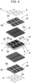
- a power supply device shown in FIGS. 1 to 3 is configured to be used for, e.g. an electric device, such as a base station, installed outdoors, and is suitable for an application in a use environment of low temperature.
- the power supply device is therefore used from low to high temperatures, for example, at ambient temperatures ranging from -30°C to 80°C.
- the power supply device for outdoors is also required to have excellent durability and strength.
- battery block 10 is accommodated in battery case 20.
- Sheet heaters 3 is configured to heat battery cells 1 constituting battery block 10 are disposed inside battery case 20.
- Battery block 10 is divided into core modules 9.
- Each of core modules 9 includes a group of battery cells 1. In this core module 9, the group of battery cells 1 are disposed parallel to one another.
- Core modules 9 have negative electrode surface 9B and positive electrode surfaces 9A.
- Each of the core modules has a corresponding one of negative electrode surfaces 9B and a corresponding one of positive electrode surfaces 9A.
- Negative electrodes 1B of the group of battery cells 1 are flush with corresponding one of negative electrode surfaces 9B.
- lead plate 2 is disposed on each of negative electrode surfaces 9B and each of positive electrode surfaces 9A.
- Negative electrode lead plate 2B on negative electrode surface 9B is connected to negative electrodes 1B of the group of battery cells 1
- positive electrode lead plate 2A on positive electrode surface 9A is connected to positive electrodes 1A of the group of battery cells 1, so that battery cells 1 are connected in parallel.
- the plurality of core modules 9 are disposed in an array where negative electrode surface 9B and positive electrode surface 9A are alternately located in a same plane.
- the plurality of core modules 9 are disposed, positive electrode surface 9A being disposed between negative electrode surfaces 9B, negative electrode surface 9B being disposed between positive electrode surfaces 9A.
- the plurality of battery cells 1 are connected by lead plate 2, each of negative electrode surface 9B and positive electrode surface 9A having an elongated shape.
- the plurality of battery cells 1 are disposed in multiple stages and multiple rows, and each of negative electrode surface 9B and positive electrode surface 9A has an elongated shape.
- the plurality of core modules 9 are disposed, elongated negative electrode surfaces 9B and positive electrode surfaces 9A being parallel to one another.
- negative electrode lead plate 2B made of one metal plate is disposed on negative electrode surface 9B
- positive electrode lead plate 2Amade of one metal plate is disposed on positive electrode surface 9A
- negative electrodes 1B of battery cells 1 are welded to negative electrode lead plate 2B
- positive electrodes 1A are welded to positive electrode lead plate 2A
- all battery cells 1 are connected in parallel by negative electrode lead plates 2B and positive electrode lead plates 2A.
- core modules 9 are disposed in multiple stages and multiple rows.
- fourteen core modules 9 are disposed in two columns and seven rows while space 11 is provided between the two columns of core modules 9.
- positive electrode lead plates 2A and negative electrode lead plates 2B are connected in series to one another.
- negative electrode lead plates 2B and positive electrode lead plates 2A are alternately disposed, and therefore, core modules 9 are connected in series by connecting lead plates 2 adjacent to each other.
- the two columns of core modules 9 may be connected to each other in series or in parallel.
- core modules 9 disposed in tow the upper and lower columns shown in the figure, core modules 9 in the upper column and core modules 9 in the lower column are disposed while negative electrode surfaces 9B and positive electrode surfaces 9A are alternately disposed. That is, each of negative electrode surfaces 9B of core modules 9 in the upper column are disposed between negative electrode surfaces 9B of core modules 9 in the lower column, and each of positive electrode surfaces 9A of core modules 9 in the upper column is disposed between positive electrode surfaces 9A of core modules 9 in the lower column.
- negative electrode surfaces 9B heated by each of sheet heaters 3 can be uniformly dispersed and disposed on the whole surface of battery block 10 to uniformly heat whole battery cells 1.
- sheet heater 3 includes base sheet 4 made of nonwoven fabric, heater wire 5 with which base sheets 4 is sewn, and insulating sheet 6 protecting heater wire 5.
- Base sheet 4 and insulating sheet 6 are flexible and cushioning nonwoven fabrics with, for example, plastic fibers three-dimensionally assembled without directionality.
- Heater wires5 is a flexible resistive wire having a surface insulated by an insulating film. A surface of each base sheet 4 is sewn with the wire in a predetermined shape.
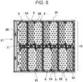
- Sheet heater 3 can adjust a partially heating state in accordance with a shape of heater wire 5 in base sheet 4. This is because heater wire 5 can be sewn in an optimum pattern to increase an amount of heat generation per unit area.
- heater wire 5 in base sheet 4 such manner that battery cells 1 of each of core modules 9 may be uniformly heated.
- Battery block 10 is cooled by battery case 20, and a temperature of an outer peripheral portion is lower than that of a central portion. Therefore, in the outer peripheral portion of battery block 10, sheet heater 3 is sewn in a heater pattern denser than in the central portion to reduce temperature differences among all heated battery cells 1.
- Sheet heater 3 is disposed at a position opposed to battery cells 1 not on a side of positive electrodes 1A, but only on one surface on a side of negative electrodes 1B, and is thermally coupled to battery cells 1 with lead plate 2 interposed to heat battery cells 1 from the side of negative electrodes 1B.
- Sheet heater 3 configured to heat negative electrodes 1B without heating positive electrodes 1A is placed on the side of negative electrode surface 9B of one surface of core module 9, and thermally coupled to a surface of negative electrode lead plate 2B. Sheet heater 3 heats each of battery cells 1 from the side of negative electrode 1B, which is one end portion, with negative electrode lead plate 2B interposed, and heats battery cell 1 from a bottom surface of an exterior can.
- one sheet heater 3 is disposed on a surface of battery block 10 to heat a group pf battery cells 1 of each of core modules 9 from the side of negative electrodes 1B.
- heating sheet portion 3A is provided at a position facing negative electrode surface 9B of each of core modules 9, and adjacent heating sheet portions 3A are joined by joining sheet portions 3B.
- Sheet heater 3 heats battery cells 1 from the side of negative electrodes 1B by disposing each of heating sheet portions 3A facing negative electrode surface 9B of each of core modules 9.
- Each of joining sheet portions 3B is disposed at a position facing positive electrode surface 9A of core module 9, and is disposed in a state insulated from positive electrode surface 9A.
- Sheet heater 3 has a single sheet shape as a whole by joining heating sheet portions 3A with joining sheet portions 3B.
- heating sheet portions 3A and joining sheet portions 3B have a unified structure, it is not necessary to connect heating sheet portions with lead wires as in a conventional sheet heater.
- each of the lead wires is connected to the heater wire of each of heating sheet portions, and the adjacent heating sheet portions are electrically connected via this lead wire. Therefore, there are disadvantages that it takes time and effort to connect the heater wires and the lead wires, so that manufacturing efficiency is deteriorated and manufacturing cost is increased, and that a connection portion between each of the heater wires and each of the lead wires is easily disconnected.
- the heater pattern is more densely arranged to increase the amount of heat generation in the outer portion of battery block 10 where heat is easily dissipated.
- the heater pattern is sparsely arranged to reduce the amount of heat generation in an inside of battery block 10 or in a vicinity where a heat generating component is disposed, so that a temperature of whole battery block 10 can be made close to uniform.
- the conventional sheet heater having a plurality of heating sheet portions connected by the lead wires is manufactured by separately manufacturing the plurality of heating sheet portions having different heater patterns and connecting the heating sheet portions having the different heater patterns by the lead wires.
- An outer shape of heating sheet portion 3A is substantially equal to an outer shape of negative electrode surface 9B of core module 9 or an outer shape of negative electrode lead plate 2B welded to negative electrode surface 9B, and all negative electrode lead plates 2B are uniformly heated.
- the outer shape of heating sheet portion 3A also has an elongated .shape.
- both end portions in a longitudinal direction are joined by joining sheet portions 3B, and heating sheet portions 3A and joining sheet portions 3B are configured of one sheet heater 3.
- both end portions of elongated heating sheet portions 3A are joined by joining sheet portions 3B, so that each of heating sheet portions 3Acan be accurately disposed on negative electrode surface 9B of core module 9 without positional deviation when heating sheet portion 3Ais set at a fixed position on the surface of battery block 10.
- Heating sheet portion 3A is placed on negative electrode lead plate 2B to heat negative electrode lead plate 2B.
- Joining sheet portion 3B is disposed with insulating gap 12 provided between joining sheet portion 3B and positive electrode surface 9A, and is disposed to be insulated from positive electrode lead plate 2A. Insulating gap 12 insulates joining sheet portion 3B from positive electrode surface 9A more reliably by insulator 13.
- joining sheet portions 3B join heater wires 5 to connect heating sheet portions 3A
- heater wires 5 are not necessarily in both joining sheet portions 3B. This is because sheet heater 3 connecting heater wires 5 of all heating sheet portions 3A in series to one another heats all heating sheet portions 3A with one heater wire 5. Since joining sheet portion 3B that heater wire 5 is not connected to does not need to be insulated from positive electrode surface 9A, joining sheet portion 3B does not necessarily need to provide insulating gap 12 or insulator 13 between joining sheet portion 3B and positive electrode surface 9A.
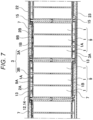
- heating sheet portion 3A of sheet heater 3 is elastically pressed against the surface of negative electrode lead plate 2B with cushion sheet 7 interposed to efficiently and uniformly heat negative electrode lead plate 2B.
- cushion sheet 7 an elastic sheet of a soft plastic foam such as a soft urethane foam as an insulator is suitable. However, a rubber-like elastic sheet that is elastically deformed by being pressing can also be used.
- Cushion sheet 7 is a sheet thicker than a distance between battery case 20 and negative electrode lead plate 2B in a non-pressing state, and elastically presses heating sheet portion 3A against negative electrode lead plate 2B in a state where cushion sheet 7 is sandwiched and crushed between battery case 20 and negative electrode lead plate 2B.
- Cushion sheet 7 has an outer shape substantially identical to the outer shape of heating sheet portion 3A, and is placed only on the surface opposed to negative electrode lead plate 2B and not on the surface opposed to positive electrode lead plate 2A.
- gap 14 configured to discharge released gas from a discharge valve (not shown) provided on the side of positive electrodes 1A of battery cells 1 can be provided between battery case 20 and positive electrode lead plate 2A. Further, it is also possible to prevent an adverse effect that moisture absorbed by cushion sheet 7 causes a short circuit on the side of positive electrodes 1A of battery cells 1.
- battery case 20 houses battery block 10, and an upper opening portion of intermediate case 21 is closed by upper surface plate 22 and a lower opening portion is closed by lower surface plate 23.
- Intermediate case 21, upper surface plate 22, and lower surface plate 23 are made of metal, and are joined by a structure such as screwing, so that an inside has a closed structure.
- core modules 9 of battery block 10 battery cells 1 are disposed in a holder portion provided in plastic battery holder 8, and the plurality of battery cells 1 are disposed at fixed positions. Since battery holder 8 is manufactured by molding plastic as an insulator, peripheries of core modules 9 are insulated by battery holder 8. The peripheries of core modules 9 are insulated by battery holder 8, but conductive portions are exposed on the surfaces where negative electrode lead plate 2B and positive electrode lead plate 2A are disposed.
- insulating plates 15 such as plastic plates as insulators are disposed on inner surfaces of upper surface plate 22 and lower surface plate 23.
- insulating plates 15 can insulate the inner surface of upper surface plate 22 and the inner surface of lower surface plate 23 to prevent negative electrode lead plates 2B and positive electrode lead plates 2A from coming into contact with metal battery case 20.
- insulating plates 15 closing the upper and lower opening portions of intermediate case 21 are each provided with elastic bent portions 15A bent into a V-shape on outer peripheral edges. Each of elastic bent portions 15A is inserted into a gap between peripheral wall 24 of intermediate case 21 and battery block 10 to close the opening portion of intermediate case 21 without a gap.
- the air heated by sheet heaters 3 is prevented from leaking to the outside and circulating, thereby increasing heating efficiency of the battery cells 1 by sheet heaters 3 and uniformly heating all the battery cells 1 via the heated internal air.
- Power supply device 100 described above is assembled in the following processes.
- Battery cells 1 are placed at the fixed positions of plastic battery holder 8. After that, negative electrode lead plates 2B are welded to negative electrodes 1B of battery cells 1, and positive electrode lead plates 2A are welded to positive electrodes 1A to manufacture battery block 10.
- battery block 10 is divided into core modules 9, in each of core modules 9, negative electrode lead plate 2B is welded to the side of negative electrodes 1B of battery cells 1, and positive electrode lead plate 2Ais welded to the side of positive electrodes 1A.
- negative electrode lead plate 2B and positive electrode lead plate 2A are alternately disposed, and negative electrode lead plates 2B and positive electrode lead plates 2A are connected in series by lead plate 2.
- adjacent core modules 9 are connected in parallel by connecting lead plates 2 on the opposite side of adjacent core modules 9.
- Each of sheet heaters 3 is disposed on respective one of the surfaces of battery block 10.
- heating sheet portions 3A are bonded to negative electrode lead plates 2B with a double-sided tape (not shown), and joining sheet portions 3B are disposed at positions facing positive electrode lead plates 2A in an insulated manner.
- each of heating sheet portions 3A is bonded to a corresponding one of negative electrode lead plates 2B in opposition to each other without being displaced.
- Each of cushion sheets 7 is bonded to the surface of a corresponding one of heating sheet portions 3A of sheet heater 3 with a double-sided adhesive tape (not shown). Cushion sheet 7 is bonded to the surface of heating sheet portion 3A without being displaced.
- intermediate case 21 The lower opening portion of intermediate case 21 is closed by lower surface plate 23 in a state where insulating plate 15 is disposed on the inner surface of lower surface plate 23.
- Lower surface plate 23 is fixed to intermediate case 21 by, for example, screwing.
- Battery block 10 with sheet heaters 3 and cushion sheets 7 bonded thereto is inserted into intermediate case 21 with the lower opening portion closed by lower surface plate 23, and is disposed at the fixed position.
- insulating plates 15 are disposed on battery block 10, and each of elastic bent portions 15A provided in the outer peripheries of a corresponding one of insulating plates 15 is inserted between peripheral wall 24 of intermediate case 21 and battery block 10.
- upper surface plate 22 is fixed to intermediate case 21, and the upper opening portion of intermediate case 21 is closed by upper surface plate 22.
- Upper surface plate 23 is fixed to intermediate case 21 by, for example, screwing.
- a power supply device includes a sheet heater configured to heat battery cells in a low temperature environment, and is suitably used in an electric device used for an application in a use environment of low temperature, for example, an electric device installed outdoors such as a base station.
Landscapes
- Chemical & Material Sciences (AREA)
- Chemical Kinetics & Catalysis (AREA)
- Electrochemistry (AREA)
- General Chemical & Material Sciences (AREA)
- Engineering & Computer Science (AREA)
- Manufacturing & Machinery (AREA)
- Physics & Mathematics (AREA)
- Electromagnetism (AREA)
- Inorganic Chemistry (AREA)
- Secondary Cells (AREA)
- Battery Mounting, Suspending (AREA)
Claims (9)
- Dispositif d'alimentation électrique (100) comprenant :un bloc-batterie (10) comportant une pluralité de cellules de batterie (1), la pluralité de cellules de batterie (1) comportant des électrodes positives (1A) et des électrodes négatives (1B), chacune de la pluralité de cellules de batterie (1) comportant une électrode correspondante des électrodes positives (1A) et une électrode correspondante des électrodes négatives (1B) aux deux extrémités de chacune de la pluralité de cellules de batterie (1) ;des plaques de conduction (2) connectées à l'électrode positive (1A) et à l'électrode négative (1B) de la pluralité de cellules de batterie (1) pour connecter électriquement les cellules de batterie (1) l'une à l'autre ; etun élément chauffant en feuille (3) configuré pour chauffer les cellules de batterie (1), dans lequell'élément chauffant en feuille (3) est placé sur une surface de la pluralité de cellules de batterie (1) via une des plaques de conduction (2) sur un côté de l'électrode négative (1B) de la pluralité de cellules de batterie (1), l'élément chauffant en feuille (3) étant couplé thermiquement aux surfaces de la pluralité de cellules de batterie (1),caractérisé en ce qu'une pluralité de modules centraux sont disposés en réseau dans le bloc-batterie (10) de sorte que des surfaces d'électrodes négatives (9B) et des surfaces d'électrodes positives (9A) soient disposées alternativement tandis qu'une ou plusieurs surfaces d'électrodes négatives (9B) parmi les surfaces d'électrodes négatives (9B) sont affleurantes avec une ou plusieurs surfaces d'électrodes positives (9A) parmi les surfaces d'électrodes positives (9A),l'élément chauffant en feuille (3) comporte :une pluralité de parties de feuilles chauffantes (3A) configurées pour chauffer les surfaces d'électrodes négatives (9B) de la pluralité de modules centraux ; etune partie de feuille d'assemblage (3B) configurée pour assembler des parties adjacentes parmi les parties de feuilles chauffantes (3A), etla partie de feuille d'assemblage (3B) est disposée à l'opposé de l'une des surfaces d'électrodes positives (9A) de la pluralité de modules centraux.
- Dispositif d'alimentation électrique (100) selon la revendication 1, dans lequelle bloc-batterie (10) est divisé en pluralité de modules centraux,la pluralité de modules centraux comportent des groupes de cellules de batterie (1) parmi la pluralité des cellules de batterie (1), chacun de la pluralité de modules centraux comporte un groupe correspondant de cellules de batterie (1),les groupes de cellules de batterie (1) de la pluralité de modules centraux sont agencés en parallèle les uns aux autres,la pluralité de modules centraux présente des surfaces d'électrodes négatives (9B) avec lesquelles les électrodes négatives (1B) des groupes de cellules de batterie (1) sont affleurantes,la pluralité de modules centraux présente des surfaces d'électrodes positives (9A) avec lesquelles les électrodes positives (1A) des groupes de cellules de batterie (1) sont affleurantes, les surfaces d'électrodes positives (9A) de la pluralité de modules centraux étant opposées aux surfaces d'électrodes négatives (9B) de la pluralité de modules centraux,les plaques de conduction (2) sont disposées sur les surfaces d'électrodes négatives (9B) et les surfaces d'électrodes positives (9A) de la pluralité de modules centraux,des plaques de conduction d'électrodes négatives (2B) parmi les plaques de conduction (2) qui se trouvent sur les surfaces d'électrodes négatives (9B) sont connectées aux électrodes négatives (1B) des groupes de cellules de batterie (1),des plaques de conduction d'électrodes positives (2A) parmi les plaques de conduction (2) qui se trouvent sur les surfaces d'électrodes positives (9A) sont connectées aux électrodes positives (1A) du groupe de cellules de batterie (1),l'élément chauffant en feuille (3) est couplé thermiquement à des surfaces des plaques de conduction d'électrodes négatives (2B) et placé sur celles-ci, sur les côtés des surfaces d'électrodes négatives (9B) de la pluralité de modules centraux, etl'élément chauffant en feuille (3) est configuré pour chauffer les groupes de cellules de batterie (1) des électrodes négatives (1B) qui sont des parties d'extrémité des groupes de cellules de batterie (1) via les plaques de conduction d'électrodes négatives (2B).
- Dispositif d'alimentation électrique (100) selon la revendication 1 ou 2, dans lequel l'élément chauffant en feuille (3) comporte :une feuille de base (4) réalisée en tissu non tissé ;un fil chauffant (5) avec lequel la feuille de base (4) est cousue ; etun feuille isolante (6) protégeant le fil chauffant (5), la feuille isolante (6) étant en contact avec ladite plaque des plaques de conduction (2).
- Dispositif d'alimentation électrique (100) selon l'une quelconque des revendications 1 à 3, dans lequelchacune des parties de feuilles chauffantes (3A) a une forme allongée, etla partie de feuille d'assemblage (3B) est assemblée aux deux parties d'extrémité des parties de feuilles chauffantes (3A) dans une direction longitudinale.
- Dispositif d'alimentation électrique (100) selon l'une quelconque des revendications 1 à 4, dans lequel la partie de feuille d'assemblage (3B) est disposée à l'écart de l'une des surfaces d'électrodes positives (9A) via un espace isolant (12) entre la partie de feuille d'assemblage (3B) et la première des surfaces d'électrodes positives (9A).
- Dispositif d'alimentation électrique (100) selon l'une quelconque des revendications 1 à 5, dans lequell'élément chauffant en feuille (3) comporte un fil chauffant (5) avec lequel la partie de feuille d'assemblage (3B) est cousue, etle fil chauffant (5) avec lequel la partie de feuille d'assemblage (3B) est cousue et le fil chauffant (5) des parties de feuilles chauffantes (3A) sont un fil chauffant (5) continu.
- Dispositif d'alimentation électrique (100) selon l'une quelconque des revendications 1 à 6, comprenant en outre :un boîtier de batterie (20) recevant le bloc-batterie (10) à l'intérieur ; etune feuille d'amortissement (7) disposée entre le boîtier de batterie (20) et chacune des parties de feuilles chauffantes (3A), dans lequella feuille d'amortissement (7) presse élastiquement les parties de feuilles chauffantes (3A) contre les plaques de conduction d'électrodes négatives (2B).
- Dispositif d'alimentation électrique (100) selon l'une quelconque des revendications 1 à 7, dans lequell'élément chauffant en feuille (3) comprend des éléments chauffants en feuille disposés sur les deux surfaces du bloc-batterie (10),les parties de feuilles chauffantes (3A) sont placées sur les plaques de conduction d'électrodes négatives (2B) de la pluralité de modules centraux, etles parties de feuilles chauffantes (3A) font face aux électrodes négatives (1B) de tous les éléments de la pluralité de cellules de batterie (1).
- Dispositif d'alimentation électrique (100) selon l'une quelconque des revendications 1 à 8, dans lequel la pluralité de cellules de batterie (1) constituée de batteries cylindriques.
Applications Claiming Priority (2)
| Application Number | Priority Date | Filing Date | Title |
|---|---|---|---|
| JP2019064716 | 2019-03-28 | ||
| PCT/JP2020/012308 WO2020196266A1 (fr) | 2019-03-28 | 2020-03-19 | Dispositif d'alimentation électrique |
Publications (4)
| Publication Number | Publication Date |
|---|---|
| EP3952008A1 EP3952008A1 (fr) | 2022-02-09 |
| EP3952008A4 EP3952008A4 (fr) | 2022-06-01 |
| EP3952008B1 true EP3952008B1 (fr) | 2023-06-21 |
| EP3952008B8 EP3952008B8 (fr) | 2023-07-26 |
Family
ID=72609876
Family Applications (1)
| Application Number | Title | Priority Date | Filing Date |
|---|---|---|---|
| EP20776764.1A Active EP3952008B8 (fr) | 2019-03-28 | 2020-03-19 | Dispositif d'alimentation électrique |
Country Status (4)
| Country | Link |
|---|---|
| US (1) | US11916214B2 (fr) |
| EP (1) | EP3952008B8 (fr) |
| JP (1) | JPWO2020196266A1 (fr) |
| WO (1) | WO2020196266A1 (fr) |
Families Citing this family (1)
| Publication number | Priority date | Publication date | Assignee | Title |
|---|---|---|---|---|
| EP4016699A1 (fr) * | 2020-12-17 | 2022-06-22 | Volvo Car Corporation | Système de gestion de température |
Family Cites Families (9)
| Publication number | Priority date | Publication date | Assignee | Title |
|---|---|---|---|---|
| JP4925680B2 (ja) | 2006-02-08 | 2012-05-09 | 三洋電機株式会社 | パック電池 |
| US20120021260A1 (en) | 2010-01-29 | 2012-01-26 | Panasonic Corporation | Battery module |
| ATE557433T1 (de) * | 2010-03-09 | 2012-05-15 | Sanyo Electric Co | Batteriepack mit leitungsplatten |
| JPWO2011135762A1 (ja) * | 2010-04-28 | 2013-07-18 | パナソニック株式会社 | 電池モジュール |
| EP3220444A1 (fr) * | 2016-03-14 | 2017-09-20 | Nordfels GmbH | Batterie |
| JP6697332B2 (ja) * | 2016-06-28 | 2020-05-20 | 三洋電機株式会社 | バッテリシステム及びバッテリシステムを備える電動車両 |
| JP6460066B2 (ja) * | 2016-08-25 | 2019-01-30 | トヨタ自動車株式会社 | 電池パック |
| US10581034B2 (en) * | 2017-03-09 | 2020-03-03 | Science Applications International Corporation | Battery assembly |
| DE102018104340A1 (de) * | 2018-02-26 | 2019-08-29 | Metabowerke Gmbh | Akkupack sowie Elektrohandwerkzeuggerät und Verfahren zur Herstellung |
-
2020
- 2020-03-19 EP EP20776764.1A patent/EP3952008B8/fr active Active
- 2020-03-19 JP JP2021509311A patent/JPWO2020196266A1/ja active Pending
- 2020-03-19 US US17/442,043 patent/US11916214B2/en active Active
- 2020-03-19 WO PCT/JP2020/012308 patent/WO2020196266A1/fr unknown
Also Published As
| Publication number | Publication date |
|---|---|
| US20220190406A1 (en) | 2022-06-16 |
| US11916214B2 (en) | 2024-02-27 |
| WO2020196266A1 (fr) | 2020-10-01 |
| JPWO2020196266A1 (fr) | 2020-10-01 |
| EP3952008A1 (fr) | 2022-02-09 |
| EP3952008B8 (fr) | 2023-07-26 |
| EP3952008A4 (fr) | 2022-06-01 |
Similar Documents
| Publication | Publication Date | Title |
|---|---|---|
| EP3343672B1 (fr) | Barres omnibus pour refroidissement d'élément de batterie et module de batterie l'utilisant | |
| KR102500561B1 (ko) | 배터리 모듈 및 이의 제조 방법 | |
| US9331313B2 (en) | Battery pack of compact structure | |
| JP6446469B2 (ja) | セル型の電気要素を接続するためのコネクタおよびかかるコネクタをバッテリユニット上に設置するための方法 | |
| CN103890997B (zh) | 中大型电池组组件 | |
| US9917294B2 (en) | Battery cell assembly of novel structure and battery pack employed with the same | |
| JP7476792B2 (ja) | 蓄電装置 | |
| EP2500958B1 (fr) | Batterie secondaire | |
| CN113383452B (zh) | 电池组件 | |
| CN107565188B (zh) | 电池包 | |
| US20220102812A1 (en) | Battery pack | |
| US20160111760A1 (en) | Power storage module | |
| CN112952249B (zh) | 电池组 | |
| KR102640328B1 (ko) | 배터리의 대형 모듈 | |
| US20140220414A1 (en) | Cap cover and battery pack including the same | |
| US20220285755A1 (en) | Top Cooling Type Battery Pack | |
| EP3952008B1 (fr) | Dispositif d'alimentation électrique | |
| JP7325442B2 (ja) | 電池モジュール | |
| US11670825B2 (en) | Battery pack | |
| KR102272268B1 (ko) | 전지 모듈용 집전시스템, 전지 모듈 및 자동차 | |
| JP2013545250A (ja) | バッテリセル | |
| US20220037719A1 (en) | Heated battery module | |
| JP7135363B2 (ja) | 蓄電装置 | |
| JP2023100002A (ja) | 蓄電装置及び蓄電設備 | |
| CN116706342A (zh) | 电池模组 |
Legal Events
| Date | Code | Title | Description |
|---|---|---|---|
| STAA | Information on the status of an ep patent application or granted ep patent |
Free format text: STATUS: THE INTERNATIONAL PUBLICATION HAS BEEN MADE |
|
| PUAI | Public reference made under article 153(3) epc to a published international application that has entered the european phase |
Free format text: ORIGINAL CODE: 0009012 |
|
| STAA | Information on the status of an ep patent application or granted ep patent |
Free format text: STATUS: REQUEST FOR EXAMINATION WAS MADE |
|
| 17P | Request for examination filed |
Effective date: 20211011 |
|
| AK | Designated contracting states |
Kind code of ref document: A1 Designated state(s): AL AT BE BG CH CY CZ DE DK EE ES FI FR GB GR HR HU IE IS IT LI LT LU LV MC MK MT NL NO PL PT RO RS SE SI SK SM TR |
|
| A4 | Supplementary search report drawn up and despatched |
Effective date: 20220503 |
|
| RIC1 | Information provided on ipc code assigned before grant |
Ipc: H01M 50/512 20210101ALI20220426BHEP Ipc: H01M 50/502 20210101ALI20220426BHEP Ipc: H01M 50/35 20210101ALI20220426BHEP Ipc: H01M 50/224 20210101ALI20220426BHEP Ipc: H01M 50/213 20210101ALI20220426BHEP Ipc: H01M 10/653 20140101ALI20220426BHEP Ipc: H01M 10/6571 20140101ALI20220426BHEP Ipc: H01M 10/6553 20140101ALI20220426BHEP Ipc: H01M 10/643 20140101ALI20220426BHEP Ipc: H01M 10/627 20140101ALI20220426BHEP Ipc: H01M 10/617 20140101ALI20220426BHEP Ipc: H01M 10/615 20140101AFI20220426BHEP |
|
| DAV | Request for validation of the european patent (deleted) | ||
| DAX | Request for extension of the european patent (deleted) | ||
| GRAP | Despatch of communication of intention to grant a patent |
Free format text: ORIGINAL CODE: EPIDOSNIGR1 |
|
| STAA | Information on the status of an ep patent application or granted ep patent |
Free format text: STATUS: GRANT OF PATENT IS INTENDED |
|
| RIC1 | Information provided on ipc code assigned before grant |
Ipc: H01M 50/512 20210101ALI20221215BHEP Ipc: H01M 50/502 20210101ALI20221215BHEP Ipc: H01M 50/35 20210101ALI20221215BHEP Ipc: H01M 50/224 20210101ALI20221215BHEP Ipc: H01M 50/213 20210101ALI20221215BHEP Ipc: H01M 10/653 20140101ALI20221215BHEP Ipc: H01M 10/6571 20140101ALI20221215BHEP Ipc: H01M 10/6553 20140101ALI20221215BHEP Ipc: H01M 10/643 20140101ALI20221215BHEP Ipc: H01M 10/627 20140101ALI20221215BHEP Ipc: H01M 10/617 20140101ALI20221215BHEP Ipc: H01M 10/615 20140101AFI20221215BHEP |
|
| INTG | Intention to grant announced |
Effective date: 20230105 |
|
| GRAS | Grant fee paid |
Free format text: ORIGINAL CODE: EPIDOSNIGR3 |
|
| GRAA | (expected) grant |
Free format text: ORIGINAL CODE: 0009210 |
|
| STAA | Information on the status of an ep patent application or granted ep patent |
Free format text: STATUS: THE PATENT HAS BEEN GRANTED |
|
| RAP3 | Party data changed (applicant data changed or rights of an application transferred) |
Owner name: SANYO ELECTRIC CO., LTD. |
|
| AK | Designated contracting states |
Kind code of ref document: B1 Designated state(s): AL AT BE BG CH CY CZ DE DK EE ES FI FR GB GR HR HU IE IS IT LI LT LU LV MC MK MT NL NO PL PT RO RS SE SI SK SM TR |
|
| REG | Reference to a national code |
Ref country code: DE Ref legal event code: R081 Ref document number: 602020012833 Country of ref document: DE Owner name: PANASONIC ENERGY CO., LTD., MORIGUCHI-SHI, JP Free format text: FORMER OWNER: SANYO ELECTRIC CO., LTD., KADOMA-SHI, OSAKA, JP |
|
| REG | Reference to a national code |
Ref country code: CH Ref legal event code: PK Free format text: BERICHTIGUNG B8 Ref country code: CH Ref legal event code: EP |
|
| REG | Reference to a national code |
Ref country code: DE Ref legal event code: R096 Ref document number: 602020012833 Country of ref document: DE |
|
| REG | Reference to a national code |
Ref country code: AT Ref legal event code: REF Ref document number: 1581565 Country of ref document: AT Kind code of ref document: T Effective date: 20230715 |
|
| RAP2 | Party data changed (patent owner data changed or rights of a patent transferred) |
Owner name: PANASONIC ENERGY CO., LTD. |
|
| REG | Reference to a national code |
Ref country code: IE Ref legal event code: FG4D |
|
| REG | Reference to a national code |
Ref country code: LT Ref legal event code: MG9D |
|
| REG | Reference to a national code |
Ref country code: NL Ref legal event code: MP Effective date: 20230621 |
|
| PG25 | Lapsed in a contracting state [announced via postgrant information from national office to epo] |
Ref country code: SE Free format text: LAPSE BECAUSE OF FAILURE TO SUBMIT A TRANSLATION OF THE DESCRIPTION OR TO PAY THE FEE WITHIN THE PRESCRIBED TIME-LIMIT Effective date: 20230621 Ref country code: NO Free format text: LAPSE BECAUSE OF FAILURE TO SUBMIT A TRANSLATION OF THE DESCRIPTION OR TO PAY THE FEE WITHIN THE PRESCRIBED TIME-LIMIT Effective date: 20230921 |
|
| REG | Reference to a national code |
Ref country code: AT Ref legal event code: MK05 Ref document number: 1581565 Country of ref document: AT Kind code of ref document: T Effective date: 20230621 |
|
| PG25 | Lapsed in a contracting state [announced via postgrant information from national office to epo] |
Ref country code: RS Free format text: LAPSE BECAUSE OF FAILURE TO SUBMIT A TRANSLATION OF THE DESCRIPTION OR TO PAY THE FEE WITHIN THE PRESCRIBED TIME-LIMIT Effective date: 20230621 Ref country code: NL Free format text: LAPSE BECAUSE OF FAILURE TO SUBMIT A TRANSLATION OF THE DESCRIPTION OR TO PAY THE FEE WITHIN THE PRESCRIBED TIME-LIMIT Effective date: 20230621 Ref country code: LV Free format text: LAPSE BECAUSE OF FAILURE TO SUBMIT A TRANSLATION OF THE DESCRIPTION OR TO PAY THE FEE WITHIN THE PRESCRIBED TIME-LIMIT Effective date: 20230621 Ref country code: LT Free format text: LAPSE BECAUSE OF FAILURE TO SUBMIT A TRANSLATION OF THE DESCRIPTION OR TO PAY THE FEE WITHIN THE PRESCRIBED TIME-LIMIT Effective date: 20230621 Ref country code: HR Free format text: LAPSE BECAUSE OF FAILURE TO SUBMIT A TRANSLATION OF THE DESCRIPTION OR TO PAY THE FEE WITHIN THE PRESCRIBED TIME-LIMIT Effective date: 20230621 Ref country code: GR Free format text: LAPSE BECAUSE OF FAILURE TO SUBMIT A TRANSLATION OF THE DESCRIPTION OR TO PAY THE FEE WITHIN THE PRESCRIBED TIME-LIMIT Effective date: 20230922 |
|
| PG25 | Lapsed in a contracting state [announced via postgrant information from national office to epo] |
Ref country code: FI Free format text: LAPSE BECAUSE OF FAILURE TO SUBMIT A TRANSLATION OF THE DESCRIPTION OR TO PAY THE FEE WITHIN THE PRESCRIBED TIME-LIMIT Effective date: 20230621 |
|
| PG25 | Lapsed in a contracting state [announced via postgrant information from national office to epo] |
Ref country code: SK Free format text: LAPSE BECAUSE OF FAILURE TO SUBMIT A TRANSLATION OF THE DESCRIPTION OR TO PAY THE FEE WITHIN THE PRESCRIBED TIME-LIMIT Effective date: 20230621 |
|
| PG25 | Lapsed in a contracting state [announced via postgrant information from national office to epo] |
Ref country code: ES Free format text: LAPSE BECAUSE OF FAILURE TO SUBMIT A TRANSLATION OF THE DESCRIPTION OR TO PAY THE FEE WITHIN THE PRESCRIBED TIME-LIMIT Effective date: 20230621 |
|
| PG25 | Lapsed in a contracting state [announced via postgrant information from national office to epo] |
Ref country code: IS Free format text: LAPSE BECAUSE OF FAILURE TO SUBMIT A TRANSLATION OF THE DESCRIPTION OR TO PAY THE FEE WITHIN THE PRESCRIBED TIME-LIMIT Effective date: 20231021 |
|
| PG25 | Lapsed in a contracting state [announced via postgrant information from national office to epo] |
Ref country code: SM Free format text: LAPSE BECAUSE OF FAILURE TO SUBMIT A TRANSLATION OF THE DESCRIPTION OR TO PAY THE FEE WITHIN THE PRESCRIBED TIME-LIMIT Effective date: 20230621 Ref country code: SK Free format text: LAPSE BECAUSE OF FAILURE TO SUBMIT A TRANSLATION OF THE DESCRIPTION OR TO PAY THE FEE WITHIN THE PRESCRIBED TIME-LIMIT Effective date: 20230621 Ref country code: RO Free format text: LAPSE BECAUSE OF FAILURE TO SUBMIT A TRANSLATION OF THE DESCRIPTION OR TO PAY THE FEE WITHIN THE PRESCRIBED TIME-LIMIT Effective date: 20230621 Ref country code: PT Free format text: LAPSE BECAUSE OF FAILURE TO SUBMIT A TRANSLATION OF THE DESCRIPTION OR TO PAY THE FEE WITHIN THE PRESCRIBED TIME-LIMIT Effective date: 20231023 Ref country code: IS Free format text: LAPSE BECAUSE OF FAILURE TO SUBMIT A TRANSLATION OF THE DESCRIPTION OR TO PAY THE FEE WITHIN THE PRESCRIBED TIME-LIMIT Effective date: 20231021 Ref country code: ES Free format text: LAPSE BECAUSE OF FAILURE TO SUBMIT A TRANSLATION OF THE DESCRIPTION OR TO PAY THE FEE WITHIN THE PRESCRIBED TIME-LIMIT Effective date: 20230621 Ref country code: EE Free format text: LAPSE BECAUSE OF FAILURE TO SUBMIT A TRANSLATION OF THE DESCRIPTION OR TO PAY THE FEE WITHIN THE PRESCRIBED TIME-LIMIT Effective date: 20230621 Ref country code: CZ Free format text: LAPSE BECAUSE OF FAILURE TO SUBMIT A TRANSLATION OF THE DESCRIPTION OR TO PAY THE FEE WITHIN THE PRESCRIBED TIME-LIMIT Effective date: 20230621 Ref country code: AT Free format text: LAPSE BECAUSE OF FAILURE TO SUBMIT A TRANSLATION OF THE DESCRIPTION OR TO PAY THE FEE WITHIN THE PRESCRIBED TIME-LIMIT Effective date: 20230621 |
|
| PG25 | Lapsed in a contracting state [announced via postgrant information from national office to epo] |
Ref country code: PL Free format text: LAPSE BECAUSE OF FAILURE TO SUBMIT A TRANSLATION OF THE DESCRIPTION OR TO PAY THE FEE WITHIN THE PRESCRIBED TIME-LIMIT Effective date: 20230621 |
|
| REG | Reference to a national code |
Ref country code: DE Ref legal event code: R097 Ref document number: 602020012833 Country of ref document: DE |
|
| PLBE | No opposition filed within time limit |
Free format text: ORIGINAL CODE: 0009261 |
|
| STAA | Information on the status of an ep patent application or granted ep patent |
Free format text: STATUS: NO OPPOSITION FILED WITHIN TIME LIMIT |
|
| PG25 | Lapsed in a contracting state [announced via postgrant information from national office to epo] |
Ref country code: DK Free format text: LAPSE BECAUSE OF FAILURE TO SUBMIT A TRANSLATION OF THE DESCRIPTION OR TO PAY THE FEE WITHIN THE PRESCRIBED TIME-LIMIT Effective date: 20230621 |
|
| PGFP | Annual fee paid to national office [announced via postgrant information from national office to epo] |
Ref country code: DE Payment date: 20240320 Year of fee payment: 5 Ref country code: GB Payment date: 20240321 Year of fee payment: 5 |
|
| PG25 | Lapsed in a contracting state [announced via postgrant information from national office to epo] |
Ref country code: SI Free format text: LAPSE BECAUSE OF FAILURE TO SUBMIT A TRANSLATION OF THE DESCRIPTION OR TO PAY THE FEE WITHIN THE PRESCRIBED TIME-LIMIT Effective date: 20230621 |